WO2019117012A1 - Élément ayant un filetage en matériau composite renforcé par des fibres de carbone - Google Patents
Élément ayant un filetage en matériau composite renforcé par des fibres de carbone Download PDFInfo
- Publication number
- WO2019117012A1 WO2019117012A1 PCT/JP2018/044937 JP2018044937W WO2019117012A1 WO 2019117012 A1 WO2019117012 A1 WO 2019117012A1 JP 2018044937 W JP2018044937 W JP 2018044937W WO 2019117012 A1 WO2019117012 A1 WO 2019117012A1
- Authority
- WO
- WIPO (PCT)
- Prior art keywords
- carbon fiber
- screw
- composite material
- reinforced composite
- nut
- Prior art date
- Legal status (The legal status is an assumption and is not a legal conclusion. Google has not performed a legal analysis and makes no representation as to the accuracy of the status listed.)
- Ceased
Links
Images




Classifications
-
- F—MECHANICAL ENGINEERING; LIGHTING; HEATING; WEAPONS; BLASTING
- F16—ENGINEERING ELEMENTS AND UNITS; GENERAL MEASURES FOR PRODUCING AND MAINTAINING EFFECTIVE FUNCTIONING OF MACHINES OR INSTALLATIONS; THERMAL INSULATION IN GENERAL
- F16B—DEVICES FOR FASTENING OR SECURING CONSTRUCTIONAL ELEMENTS OR MACHINE PARTS TOGETHER, e.g. NAILS, BOLTS, CIRCLIPS, CLAMPS, CLIPS OR WEDGES; JOINTS OR JOINTING
- F16B33/00—Features common to bolt and nut
- F16B33/006—Non-metallic fasteners using screw-thread
-
- B—PERFORMING OPERATIONS; TRANSPORTING
- B29—WORKING OF PLASTICS; WORKING OF SUBSTANCES IN A PLASTIC STATE IN GENERAL
- B29C—SHAPING OR JOINING OF PLASTICS; SHAPING OF MATERIAL IN A PLASTIC STATE, NOT OTHERWISE PROVIDED FOR; AFTER-TREATMENT OF THE SHAPED PRODUCTS, e.g. REPAIRING
- B29C43/00—Compression moulding, i.e. applying external pressure to flow the moulding material; Apparatus therefor
- B29C43/02—Compression moulding, i.e. applying external pressure to flow the moulding material; Apparatus therefor of articles of definite length, i.e. discrete articles
- B29C43/021—Compression moulding, i.e. applying external pressure to flow the moulding material; Apparatus therefor of articles of definite length, i.e. discrete articles characterised by the shape of the surface
-
- B—PERFORMING OPERATIONS; TRANSPORTING
- B29—WORKING OF PLASTICS; WORKING OF SUBSTANCES IN A PLASTIC STATE IN GENERAL
- B29C—SHAPING OR JOINING OF PLASTICS; SHAPING OF MATERIAL IN A PLASTIC STATE, NOT OTHERWISE PROVIDED FOR; AFTER-TREATMENT OF THE SHAPED PRODUCTS, e.g. REPAIRING
- B29C70/00—Shaping composites, i.e. plastics material comprising reinforcements, fillers or preformed parts, e.g. inserts
- B29C70/04—Shaping composites, i.e. plastics material comprising reinforcements, fillers or preformed parts, e.g. inserts comprising reinforcements only, e.g. self-reinforcing plastics
- B29C70/28—Shaping operations therefor
- B29C70/40—Shaping or impregnating by compression not applied
- B29C70/42—Shaping or impregnating by compression not applied for producing articles of definite length, i.e. discrete articles
- B29C70/46—Shaping or impregnating by compression not applied for producing articles of definite length, i.e. discrete articles using matched moulds, e.g. for deforming sheet moulding compounds [SMC] or prepregs
- B29C70/462—Moulding structures having an axis of symmetry or at least one channel, e.g. tubular structures, frames
-
- B—PERFORMING OPERATIONS; TRANSPORTING
- B29—WORKING OF PLASTICS; WORKING OF SUBSTANCES IN A PLASTIC STATE IN GENERAL
- B29D—PRODUCING PARTICULAR ARTICLES FROM PLASTICS OR FROM SUBSTANCES IN A PLASTIC STATE
- B29D1/00—Producing articles with screw-threads
- B29D1/005—Producing articles with screw-threads fibre reinforced
-
- C—CHEMISTRY; METALLURGY
- C08—ORGANIC MACROMOLECULAR COMPOUNDS; THEIR PREPARATION OR CHEMICAL WORKING-UP; COMPOSITIONS BASED THEREON
- C08J—WORKING-UP; GENERAL PROCESSES OF COMPOUNDING; AFTER-TREATMENT NOT COVERED BY SUBCLASSES C08B, C08C, C08F, C08G or C08H
- C08J5/00—Manufacture of articles or shaped materials containing macromolecular substances
- C08J5/04—Reinforcing macromolecular compounds with loose or coherent fibrous material
-
- C—CHEMISTRY; METALLURGY
- C08—ORGANIC MACROMOLECULAR COMPOUNDS; THEIR PREPARATION OR CHEMICAL WORKING-UP; COMPOSITIONS BASED THEREON
- C08J—WORKING-UP; GENERAL PROCESSES OF COMPOUNDING; AFTER-TREATMENT NOT COVERED BY SUBCLASSES C08B, C08C, C08F, C08G or C08H
- C08J5/00—Manufacture of articles or shaped materials containing macromolecular substances
- C08J5/04—Reinforcing macromolecular compounds with loose or coherent fibrous material
- C08J5/0405—Reinforcing macromolecular compounds with loose or coherent fibrous material with inorganic fibres
- C08J5/042—Reinforcing macromolecular compounds with loose or coherent fibrous material with inorganic fibres with carbon fibres
-
- F—MECHANICAL ENGINEERING; LIGHTING; HEATING; WEAPONS; BLASTING
- F16—ENGINEERING ELEMENTS AND UNITS; GENERAL MEASURES FOR PRODUCING AND MAINTAINING EFFECTIVE FUNCTIONING OF MACHINES OR INSTALLATIONS; THERMAL INSULATION IN GENERAL
- F16B—DEVICES FOR FASTENING OR SECURING CONSTRUCTIONAL ELEMENTS OR MACHINE PARTS TOGETHER, e.g. NAILS, BOLTS, CIRCLIPS, CLAMPS, CLIPS OR WEDGES; JOINTS OR JOINTING
- F16B25/00—Screws that cut thread in the body into which they are screwed, e.g. wood screws
- F16B25/0036—Screws that cut thread in the body into which they are screwed, e.g. wood screws characterised by geometric details of the screw
- F16B25/0094—Screws that cut thread in the body into which they are screwed, e.g. wood screws characterised by geometric details of the screw the screw being assembled or manufactured from several components, e.g. a tip out of a first material welded to shaft of a second material
-
- F—MECHANICAL ENGINEERING; LIGHTING; HEATING; WEAPONS; BLASTING
- F16—ENGINEERING ELEMENTS AND UNITS; GENERAL MEASURES FOR PRODUCING AND MAINTAINING EFFECTIVE FUNCTIONING OF MACHINES OR INSTALLATIONS; THERMAL INSULATION IN GENERAL
- F16B—DEVICES FOR FASTENING OR SECURING CONSTRUCTIONAL ELEMENTS OR MACHINE PARTS TOGETHER, e.g. NAILS, BOLTS, CIRCLIPS, CLAMPS, CLIPS OR WEDGES; JOINTS OR JOINTING
- F16B35/00—Screw-bolts; Stay-bolts; Screw-threaded studs; Screws; Set screws
-
- F—MECHANICAL ENGINEERING; LIGHTING; HEATING; WEAPONS; BLASTING
- F16—ENGINEERING ELEMENTS AND UNITS; GENERAL MEASURES FOR PRODUCING AND MAINTAINING EFFECTIVE FUNCTIONING OF MACHINES OR INSTALLATIONS; THERMAL INSULATION IN GENERAL
- F16B—DEVICES FOR FASTENING OR SECURING CONSTRUCTIONAL ELEMENTS OR MACHINE PARTS TOGETHER, e.g. NAILS, BOLTS, CIRCLIPS, CLAMPS, CLIPS OR WEDGES; JOINTS OR JOINTING
- F16B37/00—Nuts or like thread-engaging members
-
- B—PERFORMING OPERATIONS; TRANSPORTING
- B29—WORKING OF PLASTICS; WORKING OF SUBSTANCES IN A PLASTIC STATE IN GENERAL
- B29C—SHAPING OR JOINING OF PLASTICS; SHAPING OF MATERIAL IN A PLASTIC STATE, NOT OTHERWISE PROVIDED FOR; AFTER-TREATMENT OF THE SHAPED PRODUCTS, e.g. REPAIRING
- B29C43/00—Compression moulding, i.e. applying external pressure to flow the moulding material; Apparatus therefor
- B29C43/02—Compression moulding, i.e. applying external pressure to flow the moulding material; Apparatus therefor of articles of definite length, i.e. discrete articles
- B29C43/021—Compression moulding, i.e. applying external pressure to flow the moulding material; Apparatus therefor of articles of definite length, i.e. discrete articles characterised by the shape of the surface
- B29C2043/023—Compression moulding, i.e. applying external pressure to flow the moulding material; Apparatus therefor of articles of definite length, i.e. discrete articles characterised by the shape of the surface having a plurality of grooves
- B29C2043/024—Compression moulding, i.e. applying external pressure to flow the moulding material; Apparatus therefor of articles of definite length, i.e. discrete articles characterised by the shape of the surface having a plurality of grooves forming a threaded surface
-
- B—PERFORMING OPERATIONS; TRANSPORTING
- B29—WORKING OF PLASTICS; WORKING OF SUBSTANCES IN A PLASTIC STATE IN GENERAL
- B29K—INDEXING SCHEME ASSOCIATED WITH SUBCLASSES B29B, B29C OR B29D, RELATING TO MOULDING MATERIALS OR TO MATERIALS FOR MOULDS, REINFORCEMENTS, FILLERS OR PREFORMED PARTS, e.g. INSERTS
- B29K2307/00—Use of elements other than metals as reinforcement
- B29K2307/04—Carbon
-
- B—PERFORMING OPERATIONS; TRANSPORTING
- B29—WORKING OF PLASTICS; WORKING OF SUBSTANCES IN A PLASTIC STATE IN GENERAL
- B29L—INDEXING SCHEME ASSOCIATED WITH SUBCLASS B29C, RELATING TO PARTICULAR ARTICLES
- B29L2001/00—Articles provided with screw threads
- B29L2001/002—Bolts
-
- B—PERFORMING OPERATIONS; TRANSPORTING
- B29—WORKING OF PLASTICS; WORKING OF SUBSTANCES IN A PLASTIC STATE IN GENERAL
- B29L—INDEXING SCHEME ASSOCIATED WITH SUBCLASS B29C, RELATING TO PARTICULAR ARTICLES
- B29L2001/00—Articles provided with screw threads
- B29L2001/005—Nuts
Definitions
- the present invention relates to a threaded member comprising a carbon fiber reinforced composite material such as a carbon fiber reinforced plastic or a carbon fiber reinforced carbon composite material, such as a carbon fiber reinforced plastic nut.
- Bolts whose threads are formed on the outer circumferential surface and nuts whose threads are formed on the inner circumferential surface are used for fastening applications in a wide variety of structures. In applications requiring strength and durability, bolts and nuts made of metal such as stainless steel are used.
- the bolt illustrated in FIG. 1 of Patent Document 1 is embedded in the matrix in a state where a number of long carbon fibers are axially aligned as described in paragraphs 0025 to 0027 of the same document.
- a screw thread is turned on the circumference of the shank using a lathe or the like. Therefore, carbon fibers in axially adjacent threads are cut by turning, and when axial stress is applied to the threads, the threads are easily broken.
- a reinforcing fiber having the same length as that of the bolt shaft portion is previously impregnated with a matrix, and these are bundled in a round bar shape, and a male screw is formed on the inner surface.
- a method of forming a bolt shank by heating and compression in the above when the bolt shaft portion is formed by such a manufacturing method, as shown in FIG. 11, when compressed radially inward by the mold, only the matrix exudes to the outer peripheral side, so There is no reinforcing fiber and the threads are not reinforced. Therefore, if an axial stress is applied to the thread, the thread is also easily broken.
- Patent Document 2 a plurality of prepregs obtained by applying a phenolic resin to a plain weave cloth of carbon fibers are laminated, and a 2D C / C material is formed through a heating compression process and a baking process, and the C / C material is screwed.
- a method of manufacturing a fully threaded bolt by processing since the thread is formed by machining on the outer peripheral surface of the C / C material, the carbon fiber inside the axially adjacent thread is divided by being cut off by machining.
- Patent Document 3 injection-molds a round bar using short carbon fibers or pellets containing long carbon fibers as a raw material, and turning a screw thread on an outer peripheral surface or an inner peripheral surface of the round bar to form a bolt or a nut.
- a method of manufacturing is disclosed. Also in this manufacturing method, it is considered that carbon fibers inside the axially adjacent thread are cut by turning.
- Patent Document 4 discloses a bolt and a nut made of carbon fiber reinforced plastic in which carbon fiber is spirally wound along a thread groove. In such a bolt and nut, since the direction of the large axial stress acting on the thread is substantially orthogonal to the fiber direction of the carbon fiber, the thread can not be reinforced by the carbon fiber.
- the present invention proposes a novel carbon fiber embedded structure in which the threads can be reinforced by carbon fibers, thereby aiming to dramatically improve the strength of nuts and bolts in which at least the threads consist of a carbon fiber reinforced composite material. I assume.
- the present invention takes the following technical measures to achieve the above object.
- the present invention is a member having a thread made of a carbon fiber reinforced composite material, wherein a carbon fiber extending in an axial direction across at least two threads in a longitudinal cross section is a longitudinal section of the at least two threads. It is characterized in that it is embedded in a zigzag shape in the at least two threads so as to conform to the surface shape in.
- the carbon fiber reinforced composite material includes carbon fiber reinforced plastic and carbon fiber reinforced carbon composite material (hereinafter referred to as "C / C composite").
- the carbon fiber as the reinforcing fiber is preferably a carbon continuous fiber extending over the entire length of the threaded region of the member, but is a long carbon fiber extending axially in a part of the threaded region. May be
- the plastic as the matrix of the carbon fiber reinforced composite material is preferably a thermosetting plastic, but may be a thermoplastic plastic.
- a screw thread made of a C / C composite can be manufactured by carbonizing the plastic of the matrix by forming a screw thread made of carbon fiber reinforced plastic and then heat treating it in an inert atmosphere, and other suitable manufacturing methods It can be manufactured.
- a feature of the present invention is the embedded structure of carbon fibers in the thread, which can be shaped by processes now known as to the matrix and as will be developed in the future.
- the body of the member may be an injection-molded article of carbon fiber reinforced plastic reinforced by carbon short fibers, or the member body may be formed of a general plastic or metal containing no reinforcing fiber.
- the zigzag embedded in the at least two threads so as to conform to the surface shape in the longitudinal cross section of the at least two threads means that the carbon fiber itself also forms at least two peaks. It means that it is bent in a zigzag shape, and with such a configuration, the spaces between adjacent threads in the axial direction in the longitudinal cross-section can be reinforced by the carbon fibers, and the strength of the threads can be greatly improved.
- the screw thread of the present invention may be a single-threaded screw, a double-threaded screw, or a multi-threaded screw having three or more threads.
- the member is typically a nut.
- the nut of the present invention has a screw hole having on its inner circumferential surface an internal thread formed by the threads, and the carbon fiber is preferably a continuous fiber continuous over substantially the entire axial length of the internal thread. . According to a nut having a screw thread made of such a carbon fiber reinforced composite material, it becomes excellent in strength while achieving weight reduction, and various fields requiring strength while achieving weight reduction, such as aircraft and space development fields , Automobiles, motorcycles, railroads, and various fixed structures.
- the nut preferably includes a nut body having a mounting hole, and a screw cylinder integrally fitted to the mounting hole of the nut body, and the female screw is provided on the screw cylinder.
- the nut body can be formed relatively inexpensively, and the strength of the screw thread can be improved while reducing the cost of the entire nut.
- the member may be a bolt.
- the bolt of the present invention preferably has a screw shaft having an external thread formed by the threads on the outer peripheral surface, and the carbon fiber is a continuous fiber which is continuous over substantially the entire axial length of the external thread.
- the screw shaft of the bolt may include a shaft body and a screw cylinder integrally fitted on an outer peripheral surface of the shaft body, and the male screw may be provided on the screw cylinder.
- the carbon fiber may be a carbon long fiber having a fiber length required to be embedded in a zigzag in the at least two threads.
- a nut and a bolt can be illustrated typically as a member of the present invention, it may be any member having a screw hole or a screw shaft, a structural material of a building or other fixed structure, an automobile And parts that make up the body or frame of an airplane,
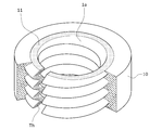
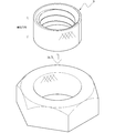
- FIG. 1 shows a carbon fiber reinforced plastic nut 1 according to an embodiment of the present invention, and the nut 1 is a screw hole 1a having an internal thread composed of a helical thread Th on the inner peripheral surface.
- the nut 1 is provided with a nut body 10 constituting an outer peripheral portion of the nut and a screw cylinder 11 constituting an inner peripheral portion of the nut, and the nut main body 10 is integrally formed on the outer peripheral side of the screw cylinder 11
- the female screw is provided on the screw cylinder 11.
- the outer peripheral surface of the nut body 10 is formed in a hexagonal column shape.
- Both the nut body 10 and the screw cylinder 11 are preferably made of carbon fiber reinforced plastic.
- the plastic to be the matrix is preferably a thermosetting plastic from the viewpoint of heat resistance, but thermoplastic plastics can also be used in applications where heat resistance is not required.
- thermosetting plastic epoxy resin, phenol resin, unsaturated polyester resin and the like can be used.
- thermoplastics polyamide, polypropylene and polycarbonate can be used.
- carbon fiber as a reinforcing material any of PAN-based carbon fiber and pitch-based carbon fiber may be adopted.
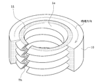
- the nut main body 10 can be integrally formed, for example, by injection molding on the outer peripheral side of the screw cylinder 11. In addition, it is shown in FIG. 2 by winding a prepreg tape around the outer periphery of the screw cylinder 11 and heat curing. After molding such an intermediate product, the outer peripheral surface thereof can be manufactured by an appropriate manufacturing method such as molding by cutting or the like. Also, the reinforcing fibers of the nut body 10 may be carbon short fibers or carbon long fibers, and as shown in FIG. 3, carbon continuous fibers whose fiber direction is aligned in the circumferential direction It may be. The preferred carbon fiber content of the nut body 10 is 20 to 30% by weight or 20 to 30% by volume.
- the carbon fiber content of the screw cylinder 3 is 50 to 90. % By weight or 50 to 90% by volume.
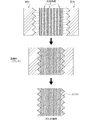
- Each carbon continuous fiber extends in the axial direction over all the threads Th arranged in the axial direction in the longitudinal cross section, and has a surface shape (inner surface shape in the present embodiment) in the longitudinal cross section of all the threads Th. It is embedded in a zigzag shape on all the threads Th so as to be along.
- the carbon continuous fibers do not have to be bent so as to completely match the surface shape of the screw thread Th, and may be bent so as to be substantially present in each screw thread Th.
- Carbon short fibers or carbon long fibers may be embedded together with the carbon continuous fibers, and some carbon continuous fibers may be aligned along the spiral direction of the circumferential direction or thread Th.
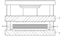
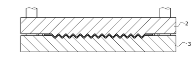
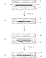
- a corrugated sheet member 6 made of carbon fiber reinforced plastic as shown in FIG. 6 is molded using a press shown in FIGS. 4 and 5.
- the press machine comprises an upper die 2 and a lower die 3 and on the opposing surfaces of these upper and lower dies 2 and 3, a die surface having a corrugated cross-section is formed.
- the upper and lower molds 2 and 3 are opened, and a plurality of sheet-like carbon fiber unidirectional materials 4 between the upper and lower molds 2 and 3 and a plurality of thermoplastic plastic sheets 5 to be a matrix are provided.
- the corrugated member 6 shown in FIG. 6 is formed by clamping, heating and pressurizing.
- thermosetting resin when using a thermosetting resin as a matrix, it can shape
- FIGS. 4 and 5 is illustrated as a mold for forming a flat plate-like corrugated plate member, a mold structure for forming a cylindrical member as shown in FIG. 7 can also be used.
- the method of molding the nut body 10 on the outer peripheral side of the screw cylinder 11 may be any method. Further, as shown in FIG. 8, the mounting hole 10 a is provided in the nut body 10, and the intermediate product 7 shown in FIG. 2 or 3 is press-fitted into the mounting hole 10 a to firmly bond the contact surface. You can also In this case, as shown in FIG. 8, knurling may be applied to the inner peripheral surface of the mounting hole 10a and the outer peripheral surface of the intermediate product 7 in order to improve the adhesion between the contact surfaces. .
- the intermediate product 7 shown in FIG. 8 can also be formed by curving a plate material having one side formed by the two-step pressing process shown in FIG. .
- the primary pressing step of FIG. 9 (b) is a step mainly for embedding carbon continuous fibers in a zigzag shape. Through this process, carbon continuous fibers can be reliably bent in a zigzag manner.
- the secondary pressing step shown in FIGS. 9 (c) and 9 (d) is a step mainly for making one side face flat, and the wave plate member 6 is transferred to the other upper and lower dies 20, 30, and carbon fibers are further formed thereon.
- the sheet 4 and the resin sheet 5 are laminated and pressed.
- the present invention can also be applied to a special locking double lock that is manufactured and sold by the applicant of the present application, as shown in FIG. 10, that is, a HARDLOCK nut (trademark International Registration No. 1224310). Moreover, not only a nut but a bolt can also be applied. Furthermore, the present invention can be applied to various members having screw holes and screw shafts.
- the said manufacturing method can replace with a carbon fiber sheet and can also use the prepreg in which resin was made to penetrate carbon continuous fiber beforehand.
- carbon fibers are formed by molding using a powder-impregnated yarn in which resin powder is attached to carbon fibers, or a combing yarn in which resin fibers are mixed and woven with carbon fiber bundles. Can also improve the impregnation of the
Landscapes
- Engineering & Computer Science (AREA)
- General Engineering & Computer Science (AREA)
- Chemical & Material Sciences (AREA)
- Mechanical Engineering (AREA)
- Organic Chemistry (AREA)
- Chemical Kinetics & Catalysis (AREA)
- Medicinal Chemistry (AREA)
- Polymers & Plastics (AREA)
- Health & Medical Sciences (AREA)
- Materials Engineering (AREA)
- Manufacturing & Machinery (AREA)
- Inorganic Chemistry (AREA)
- Composite Materials (AREA)
- Physics & Mathematics (AREA)
- Geometry (AREA)
- Moulding By Coating Moulds (AREA)
- Reinforced Plastic Materials (AREA)
Abstract
La présente invention concerne un élément ayant un filetage en matériau composite renforcé par des fibres de carbone ayant une résistance élevée. L'élément a une structure dans laquelle une fibre de carbone s'étendant dans une direction axiale à travers au moins deux filetages dans une section transversale verticale est incorporée en zigzag dans au moins les deux filetages de façon à suivre la forme de surface desdits au moins deux filetages dans la section transversale verticale. De préférence, l'élément est un écrou dans lequel la structure est incorporée dans les filetages de la vis femelle de l'écrou, fournissant ainsi un écrou léger et résistant.
Priority Applications (4)
| Application Number | Priority Date | Filing Date | Title |
|---|---|---|---|
| KR1020207016487A KR102647293B1 (ko) | 2017-12-12 | 2018-12-06 | 탄소 섬유 강화 복합 재료로 이루어지는 나사산을 갖는 나사통의 제조 방법 |
| US16/767,511 US20200378430A1 (en) | 2017-12-12 | 2018-12-06 | Member having screw thread made from carbon fiber-reinforced composite material |
| EP18887941.5A EP3726073B1 (fr) | 2017-12-12 | 2018-12-06 | Élément ayant un filetage en matériau composite renforcé par des fibres de carbone |
| CN201880079285.9A CN111448398B (zh) | 2017-12-12 | 2018-12-06 | 具有由碳纤维强化复合材料构成的螺纹牙的螺纹筒的制造方法 |
Applications Claiming Priority (2)
| Application Number | Priority Date | Filing Date | Title |
|---|---|---|---|
| JP2017237462A JP6659658B2 (ja) | 2017-12-12 | 2017-12-12 | 炭素繊維強化複合材料からなるネジ山を有するネジ筒の製造方法 |
| JP2017-237462 | 2017-12-12 |
Publications (1)
| Publication Number | Publication Date |
|---|---|
| WO2019117012A1 true WO2019117012A1 (fr) | 2019-06-20 |
Family
ID=66819169
Family Applications (1)
| Application Number | Title | Priority Date | Filing Date |
|---|---|---|---|
| PCT/JP2018/044937 Ceased WO2019117012A1 (fr) | 2017-12-12 | 2018-12-06 | Élément ayant un filetage en matériau composite renforcé par des fibres de carbone |
Country Status (6)
| Country | Link |
|---|---|
| US (1) | US20200378430A1 (fr) |
| EP (1) | EP3726073B1 (fr) |
| JP (1) | JP6659658B2 (fr) |
| KR (1) | KR102647293B1 (fr) |
| CN (1) | CN111448398B (fr) |
| WO (1) | WO2019117012A1 (fr) |
Cited By (1)
| Publication number | Priority date | Publication date | Assignee | Title |
|---|---|---|---|---|
| RU214781U1 (ru) * | 2022-08-29 | 2022-11-14 | Владимир Васильевич Галайко | Гайка из композитного материала |
Families Citing this family (10)
| Publication number | Priority date | Publication date | Assignee | Title |
|---|---|---|---|---|
| JP7236725B2 (ja) * | 2018-01-11 | 2023-03-10 | 株式会社タカイコーポレーション | 繊維強化樹脂製ボルト製造方法及び繊維強化樹脂製ボルト |
| US11387163B2 (en) * | 2018-03-30 | 2022-07-12 | Intel Corporation | Scalable debris-free socket loading mechanism |
| US11449111B2 (en) | 2018-03-30 | 2022-09-20 | Intel Corporation | Scalable, high load, low stiffness, and small footprint loading mechanism |
| US11557529B2 (en) | 2018-03-30 | 2023-01-17 | Intel Corporation | Mechanism combining fastener captivation and assembly tilt control for microprocessor thermal solutions |
| JP2021098280A (ja) * | 2019-12-20 | 2021-07-01 | 国立大学法人金沢大学 | 機能性部品の製造方法 |
| CN112339355B (zh) * | 2020-09-30 | 2025-01-21 | 山东中航和辉复合材料有限公司 | 一种热塑性复合螺母及其制备方法与应用 |
| JP7320578B2 (ja) * | 2021-11-09 | 2023-08-03 | 株式会社Cfcデザイン | 異方性不織布を積層した2次元炭素/炭素複合材料製ネジ部品 |
| CN115353405B (zh) * | 2022-09-19 | 2023-02-10 | 陕西美兰德炭素有限责任公司 | 一种高强度碳/碳紧固件的制备方法 |
| CN115894048B (zh) * | 2022-10-12 | 2023-09-26 | 安徽精亘机械科技有限公司 | 一种碳纤维与陶瓷结构化复合增强型螺栓 |
| CN116572555A (zh) * | 2023-05-30 | 2023-08-11 | 东莞市麦星匠碳纤维科技有限公司 | 热固性碳纤维增强型复合材料螺丝的制备方法 |
Citations (9)
| Publication number | Priority date | Publication date | Assignee | Title |
|---|---|---|---|---|
| JPS59147111A (ja) * | 1983-02-10 | 1984-08-23 | 積水化学工業株式会社 | 合成樹脂製ボルトの製造方法 |
| JPH0396709A (ja) * | 1989-09-11 | 1991-04-22 | Fukuvi Chem Ind Co Ltd | 合成樹脂製締結部材 |
| JPH04331811A (ja) * | 1991-04-30 | 1992-11-19 | Kawasaki Steel Corp | C/c製転造ねじおよびその製造方法 |
| JPH05177727A (ja) * | 1991-12-27 | 1993-07-20 | Mikio Sakai | 合成樹脂製ナット部材およびその製造方法 |
| JPH09254266A (ja) | 1996-03-24 | 1997-09-30 | Railway Technical Res Inst | 繊維強化樹脂材料製ボルト、及び繊維強化樹脂材料製ナット |
| JP2001289226A (ja) | 2000-01-11 | 2001-10-19 | Toyo Tanso Kk | 炭素繊維強化炭素複合材料製ネジ |
| JP2016088073A (ja) | 2014-11-04 | 2016-05-23 | エフテックス有限会社 | 炭素繊維強化ポリエステル樹脂のボルトナットの製造方法 |
| JP2017003091A (ja) * | 2015-06-15 | 2017-01-05 | 三星産業貿易株式会社 | ねじ締結部品の製造方法 |
| JP2017067129A (ja) | 2015-09-29 | 2017-04-06 | 日本精工株式会社 | ねじ軸、ナット、ボールねじ装置 |
Family Cites Families (16)
| Publication number | Priority date | Publication date | Assignee | Title |
|---|---|---|---|---|
| US2549393A (en) * | 1945-03-23 | 1951-04-17 | Josephine M Siesel | Fastening |
| US2762119A (en) * | 1953-04-22 | 1956-09-11 | John E Jackson | Method of making a bolt anchor shield |
| KR830008061A (ko) * | 1981-12-03 | 1983-11-09 | 원본미기재 | 내부밴드를 갖는 너트 |
| US4778637A (en) * | 1984-06-18 | 1988-10-18 | Tiodize Company, Inc, | Method of forming a composite fastener |
| JPH074874B2 (ja) * | 1988-04-12 | 1995-01-25 | 東レ株式会社 | 繊維強化複合材からなるネジ状成形体の製造方法 |
| WO1991002906A1 (fr) * | 1989-08-23 | 1991-03-07 | Textron Inc. | Dispositf de fixation composite ameliore ainsi que son procede et son appareil de fabrication |
| US5080547A (en) * | 1990-03-30 | 1992-01-14 | The B. F. Goodrich Company | Triaxially braided composite nut and bolt |
| JPH07335453A (ja) * | 1994-04-14 | 1995-12-22 | Soshin Denki Kk | ハウジング、ハウジング形成用金属薄板及び部品製造方法 |
| JP3460429B2 (ja) * | 1996-02-23 | 2003-10-27 | 石川島播磨重工業株式会社 | 繊維強化ボルト |
| CN2729395Y (zh) * | 2004-10-20 | 2005-09-28 | 孟庚平 | 高强耐腐内螺纹连接器 |
| KR20100130286A (ko) * | 2009-06-03 | 2010-12-13 | 에스케이케미칼주식회사 | 섬유강화수지 볼트 및 그 제조방법 |
| DE102010036218A1 (de) * | 2010-08-27 | 2012-03-01 | Brandenburgische Technische Universität Cottbus | Schichtelement aus strukturierten wabenförmigen Schichten |
| JP5959558B2 (ja) * | 2014-03-13 | 2016-08-02 | アイシン高丘株式会社 | 複合構造体及びその製造方法 |
| JP6005086B2 (ja) * | 2014-03-13 | 2016-10-12 | アイシン高丘株式会社 | 複合構造体の製造方法 |
| CN107127984A (zh) * | 2017-05-25 | 2017-09-05 | 广州赛奥碳纤维技术有限公司 | 一种连续纤维增强热塑性树脂基复合材料制造工艺 |
| AU2020478278B2 (en) * | 2020-11-30 | 2024-05-23 | Arctic Biomaterials Oy | Method for manufacturing fiber reinforced article and apparatus |
-
2017
- 2017-12-12 JP JP2017237462A patent/JP6659658B2/ja active Active
-
2018
- 2018-12-06 US US16/767,511 patent/US20200378430A1/en not_active Abandoned
- 2018-12-06 KR KR1020207016487A patent/KR102647293B1/ko active Active
- 2018-12-06 EP EP18887941.5A patent/EP3726073B1/fr active Active
- 2018-12-06 WO PCT/JP2018/044937 patent/WO2019117012A1/fr not_active Ceased
- 2018-12-06 CN CN201880079285.9A patent/CN111448398B/zh active Active
Patent Citations (9)
| Publication number | Priority date | Publication date | Assignee | Title |
|---|---|---|---|---|
| JPS59147111A (ja) * | 1983-02-10 | 1984-08-23 | 積水化学工業株式会社 | 合成樹脂製ボルトの製造方法 |
| JPH0396709A (ja) * | 1989-09-11 | 1991-04-22 | Fukuvi Chem Ind Co Ltd | 合成樹脂製締結部材 |
| JPH04331811A (ja) * | 1991-04-30 | 1992-11-19 | Kawasaki Steel Corp | C/c製転造ねじおよびその製造方法 |
| JPH05177727A (ja) * | 1991-12-27 | 1993-07-20 | Mikio Sakai | 合成樹脂製ナット部材およびその製造方法 |
| JPH09254266A (ja) | 1996-03-24 | 1997-09-30 | Railway Technical Res Inst | 繊維強化樹脂材料製ボルト、及び繊維強化樹脂材料製ナット |
| JP2001289226A (ja) | 2000-01-11 | 2001-10-19 | Toyo Tanso Kk | 炭素繊維強化炭素複合材料製ネジ |
| JP2016088073A (ja) | 2014-11-04 | 2016-05-23 | エフテックス有限会社 | 炭素繊維強化ポリエステル樹脂のボルトナットの製造方法 |
| JP2017003091A (ja) * | 2015-06-15 | 2017-01-05 | 三星産業貿易株式会社 | ねじ締結部品の製造方法 |
| JP2017067129A (ja) | 2015-09-29 | 2017-04-06 | 日本精工株式会社 | ねじ軸、ナット、ボールねじ装置 |
Non-Patent Citations (1)
| Title |
|---|
| See also references of EP3726073A4 |
Cited By (1)
| Publication number | Priority date | Publication date | Assignee | Title |
|---|---|---|---|---|
| RU214781U1 (ru) * | 2022-08-29 | 2022-11-14 | Владимир Васильевич Галайко | Гайка из композитного материала |
Also Published As
| Publication number | Publication date |
|---|---|
| CN111448398B (zh) | 2021-09-07 |
| KR102647293B1 (ko) | 2024-03-12 |
| JP6659658B2 (ja) | 2020-03-04 |
| EP3726073B1 (fr) | 2023-06-07 |
| JP2019105299A (ja) | 2019-06-27 |
| EP3726073A4 (fr) | 2020-12-16 |
| EP3726073A1 (fr) | 2020-10-21 |
| CN111448398A (zh) | 2020-07-24 |
| US20200378430A1 (en) | 2020-12-03 |
| KR20200095486A (ko) | 2020-08-10 |
Similar Documents
| Publication | Publication Date | Title |
|---|---|---|
| JP2019105299A (ja) | 炭素繊維強化複合材料からなるネジ山を有する部材 | |
| US4863330A (en) | Composite fastener and method of manufacture | |
| US12076942B2 (en) | Method for manufacturing fiber-reinforced resin bolt and fiber-reinforced resin bolt | |
| US20140212624A1 (en) | Fiber-reinforced resin member and method for manufacturing fiber-reinforced resin member | |
| EP0258477A1 (fr) | Dispositif de fixation en matériau composite | |
| EP3559486B1 (fr) | Insert de fixation pour un élément en matière plastique, en mousse ou en matériau composite | |
| KR20100130286A (ko) | 섬유강화수지 볼트 및 그 제조방법 | |
| TWI862676B (zh) | 產生應用在拉壓桿之正鎖定載重的方法及拉壓桿 | |
| JP6304804B2 (ja) | バー状部品の製造方法およびバー状部品 | |
| DE102005020907A1 (de) | Hohlstruktur aus faserverstärktem Kunststoff mit Lasteinleitungselementen | |
| WO2016173587A1 (fr) | Capuchon polaire notamment pour récipient sous pression et procédé de fabrication de capuchon polaire et du récipient sous pression | |
| JP4930283B2 (ja) | 繊維強化樹脂製歯車 | |
| WO2005105417A1 (fr) | Structure creuse realisee en matiere plastique renforcee avec des elements d'introduction de charge | |
| DE102006047412B4 (de) | Stabförmige Faserverbundstruktur mit Lasteinleitungselementen sowie Verfahren zur Herstellung | |
| JPH0516476Y2 (fr) | ||
| JP6531920B2 (ja) | 繊維強化プラスチック製構造部材の連結構造及び連結部分の加工方法 | |
| EP3129662B1 (fr) | Pièce en matière plastique munie d'un élément d'assemblage | |
| JPH0726644B2 (ja) | 締結装置部材およびその製造方法 | |
| JP2697089B2 (ja) | 繊維補強合成樹脂製ナットの製造方法 | |
| RU2819679C1 (ru) | Способ создания приложения нагрузки с принудительной блокировкой для стержня растяжения-сжатия и соответствующий стержень | |
| CA1278202C (fr) | Organe d'assemblage composite | |
| JP2007064389A (ja) | 繊維強化樹脂製コイルバネおよびその製造方法 | |
| KR20230093935A (ko) | 열경화성 복합재 부품 성형 방법 | |
| CN102840202B (zh) | 一种螺旋键及其制作模具和制作方法 | |
| JPH0663976A (ja) | 繊維強化複合材料による成形品の成形方法 |
Legal Events
| Date | Code | Title | Description |
|---|---|---|---|
| 121 | Ep: the epo has been informed by wipo that ep was designated in this application |
Ref document number: 18887941 Country of ref document: EP Kind code of ref document: A1 |
|
| NENP | Non-entry into the national phase |
Ref country code: DE |
|
| ENP | Entry into the national phase |
Ref document number: 2018887941 Country of ref document: EP Effective date: 20200713 |