WO2019123711A1 - スプリンクラーヘッド - Google Patents
スプリンクラーヘッド Download PDFInfo
- Publication number
- WO2019123711A1 WO2019123711A1 PCT/JP2018/029863 JP2018029863W WO2019123711A1 WO 2019123711 A1 WO2019123711 A1 WO 2019123711A1 JP 2018029863 W JP2018029863 W JP 2018029863W WO 2019123711 A1 WO2019123711 A1 WO 2019123711A1
- Authority
- WO
- WIPO (PCT)
- Prior art keywords
- nozzle
- slit
- sprinkler head
- boss
- deflector
- Prior art date
- Legal status (The legal status is an assumption and is not a legal conclusion. Google has not performed a legal analysis and makes no representation as to the accuracy of the status listed.)
- Ceased
Links
Images


Classifications
-
- A—HUMAN NECESSITIES
- A62—LIFE-SAVING; FIRE-FIGHTING
- A62C—FIRE-FIGHTING
- A62C37/00—Control of fire-fighting equipment
- A62C37/08—Control of fire-fighting equipment comprising an outlet device containing a sensor, or itself being the sensor, i.e. self-contained sprinklers
- A62C37/10—Releasing means, e.g. electrically released
- A62C37/11—Releasing means, e.g. electrically released heat-sensitive
- A62C37/12—Releasing means, e.g. electrically released heat-sensitive with fusible links
-
- B—PERFORMING OPERATIONS; TRANSPORTING
- B05—SPRAYING OR ATOMISING IN GENERAL; APPLYING FLUENT MATERIALS TO SURFACES, IN GENERAL
- B05B—SPRAYING APPARATUS; ATOMISING APPARATUS; NOZZLES
- B05B1/00—Nozzles, spray heads or other outlets, with or without auxiliary devices such as valves, heating means
- B05B1/26—Nozzles, spray heads or other outlets, with or without auxiliary devices such as valves, heating means with means for mechanically breaking-up or deflecting the jet after discharge, e.g. with fixed deflectors; Breaking-up the discharged liquid or other fluent material by impinging jets
- B05B1/262—Nozzles, spray heads or other outlets, with or without auxiliary devices such as valves, heating means with means for mechanically breaking-up or deflecting the jet after discharge, e.g. with fixed deflectors; Breaking-up the discharged liquid or other fluent material by impinging jets with fixed deflectors
- B05B1/265—Nozzles, spray heads or other outlets, with or without auxiliary devices such as valves, heating means with means for mechanically breaking-up or deflecting the jet after discharge, e.g. with fixed deflectors; Breaking-up the discharged liquid or other fluent material by impinging jets with fixed deflectors the liquid or other fluent material being symmetrically deflected about the axis of the nozzle
Definitions
- the present invention relates to a sprinkler head for fire extinguishing, and more particularly to a sprinkler head for residential use.
- the sprinkler system is installed in the building and senses the heat of the fire and operates automatically to fire water and extinguish it.
- the sprinkler head has a nozzle inside, and the nozzle is connected to the pipe leading to the water supply source, and the nozzle is always in a closed state.
- the nozzle is opened, and water filled in the pipe is released from the nozzle.
- the sprinkler head is equipped with a deflector that splashes water in all directions on the extension of the nozzle outlet, and the water that has collided with the deflector is sprayed in a predetermined area to suppress and extinguish the fire.
- NFPA 13 National Fire Protection Association
- NFPA 13D The standard for residential sprinkler equipment
- UL 1626 The standard for a residential sprinkler head.
- Residential sprinkler heads are defined in UL 1626 to spray water to the walls as well as to the floor. For water sprinkling on the wall surface, the wall surface must be wet from the ceiling surface to the floor surface within a predetermined distance or less.
- U.S. Pat. No. 6,516,893 and U.S. Pat. No. 720,1234 as conventional residential sprinkler heads.
- An object of the present invention is to provide a sprinkler head which can satisfy both the amount of water sprinkling on the floor and the wetting of the wall surface.
- the present invention provides the following sprinkler head.
- a main body internally equipped with a nozzle connected to a water supply pipe, a pair of arms extending from the main body in the direction of water discharge from the main body, the tip of the arm is connected to a columnar boss installed on the central axis of the nozzle
- the screw has an eyebrow screw and is screwed into the eyebrow screw, and has an impression screw whose tip protrudes on the nozzle side, a disc-like deflector installed at the tip of a boss, and the outer circumference of the deflector toward the central axis of the nozzle It has a plurality of slits that are engraved, and a tapered slit that is tapered from the center of the deflector toward the outer periphery is installed, and the tapered slit is adjacent to a straight slit whose slit width is constant. It is a sprinkler head that has been installed.
- the sprinkler head described above is a residential sprinkler head, and the value of the K factor derived from the flow rate of the nozzle and the discharge pressure is 3 to 5.8.
- the deflector has a plurality of slits cut from its outer periphery toward the central axis of the nozzle, and a tapered slit is provided which tapers from the center of the deflector toward the outer periphery.
- the end on the nozzle center axis side is formed in an arc shape, and the width of the outer end of the deflector is smaller than the diameter of the arc.
- the water discharged from the end on the nozzle central axis side is discharged downward, and the amount of water sprinkling to the floor increases.
- the water discharged from the end on the outer peripheral side of the deflector is scattered toward the wall surface as the slit width narrows and the flow velocity increases as it approaches the tip.
- the tapered slit has an effect of increasing the amount of water sprinkling on the floor surface while suppressing a decrease in the flight distance.
- the tapered slit may be installed adjacent to a straight slit having the same width on the nozzle central axis side and the outer peripheral side of the deflector, or may be installed adjacent to a plane through which a pair of arms pass.
- the angle of the tapered slit is 8 ° to 10 °, and if the angle is smaller than this, the above effect can not be obtained. On the other hand, if the angle is too large, the momentum of water released from the outer peripheral end of the deflector is attenuated, and the flight distance in the wall surface direction becomes short.
- the shape of the deflector and the boss on which the deflector is installed and the shape of the impression screw installed on the boss can prevent the occurrence of the turbulent flow. More specifically, control of the water spray pattern is facilitated by the configuration in which turbulence is less likely to occur at the tip of the impact screw and the boundary between the impact screw and the boss where the water released from the nozzle first collides. Become.
- the tip of the impression screw protrudes toward the nozzle, and its shape is sharp. This reduces the resistance of the water flow and has the effect of evenly distributing the water colliding with the tip in four directions.
- From the tip of the impression screw to the boss side it is a slope, and the water flows along the slope.
- the extension along the slope is close to or in contact with the curved surface of the outer peripheral end of the boss, and the water flow smoothly from the slope to the curved surface of the outer peripheral end of the boss.
- the water flow passing through the outer periphery of the boss and reaching the plane of the deflector passes through the slit provided on the outer periphery of the deflector and scatters toward the floor surface. Alternatively, it reaches the outer periphery of the deflector and scatters toward the wall surface.
- the direction of the line perpendicular to the plane passing through the pair of arms and passing through the central axis of the nozzle is the position where the influence of the water flow by the arms is the least affected, and there is nothing obstructing the water flow Is smooth. Therefore, the momentum of the water is strong, and the water scatters to a further distance, so that it is possible to obtain the amount of water sprinkling exceeding the specified wet height to the wall surface.
- the amount of water spray in the short distance range immediately below the sprinkler head to be insufficient.
- the slit at this position can be made longer than the other slits to guide the water flow to the floor surface to increase the amount of water spray in the short range.
- uniform watering can be performed on the floor surface, and a desired wet height can be obtained on the wall surface.
- the present invention it is possible to realize a sprinkler head capable of satisfying both the amount of water sprinkling on the floor surface and the wetting of the wall surface. Furthermore, the occurrence of turbulent flow is prevented by suppressing the occurrence of turbulent flow at the tip of the impression screw and the boss. Furthermore, according to the sprinkler head configured as described above, it is possible to realize a sprinkler head that can clear the water spray test and the extinguishment test defined in UL 1626 with the smallest flow rate.
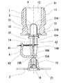
- the sprinkler head S1 of the present invention shown in FIGS. 1 and 2 is composed of a main body 1, a deflector 2, a valve 3 and a thermal decomposition section 4.
- the main body 1 has a hollow shape, and an exterior is provided with a set screw 11 for connecting to a piping on the ceiling and a ceiling, and the inside is a nozzle 12.
- the size of the nozzle 12 is such that the value of the K factor derived from the flow rate of the nozzle 12 and the discharge pressure is in the range of 3 to 5.8, and in the present embodiment, the value of the K factor is 4.9.
- the size of the female screw 11 connected to the piping is NPT1 / 2 or R1 / 2.
- a substantially rectangular base 13 is installed, and a pair of arms 14 extending from the base 13 in the water discharge direction of the nozzle 12 are installed.
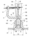
- the arm 14 includes a straight portion 14A extending substantially in parallel with the central axis A of the nozzle, and a crossing portion 14B connected to a boss 15 installed on the central axis A of the nozzle 12 from the end of the linear portion 14A. As shown in FIG. 3, the crossing portion 14B is thinner than the straight portion 14A, and its cross-sectional shape is elliptical.
- the boss 15 has a tapered cylindrical shape, and the deflector 2 is installed at the tip of the boss 15.
- the diameter D1 of the boss 15 on the side in contact with the deflector 2 is 9 to 10 mm.
- the diameter of the boss 15 on the nozzle 12 side is smaller than the diameter D1 on the deflector 2 side.
- the outer peripheral end 15A on the nozzle 12 side of the boss 15 has a curved surface shape, and the radius of the curved surface is in the range of 1 mm to 3 mm, and is 2 mm in this embodiment.
- a tack screw 15B is installed inside the boss 15, and the impression screw 16 is screwed in.
- the tip 16A of the impression screw 16 is pointed and has a bevel 16B.
- the tip 16A faces the nozzle 12, and the angle ⁇ of the slope 16B is preferably in the range of 80 ° to 100 °, and is 90 ° in the present embodiment.
- the apex of the tip 16A is spherical, and the spherical radius is preferably 2 mm or less, and is 1 mm or less in the present embodiment.
- the impression screw 16 has a function of pressing the valve 3 toward the nozzle 12 via the thermal decomposition section 4.
- the extended line 16C along the inclined surface 16B of the tip 16A of the impression screw 16 is close to or in contact with the curved surface of the outer peripheral end 15A of the boss 15, and the water flowing along the surface of the tip 16A is the outer peripheral end It does not obstruct the flow when passing 15A and prevents the occurrence of turbulent flow.
- the distance a between the slope 16B of the impression screw 16 and the end face of the boss 15 on the nozzle 12 side is 2 mm or less, and more preferably 1 mm or less. If the interval is further expanded, the possibility of the occurrence of turbulence increases.
- the deflector 2 shown in FIG. 4 has a disk shape, and the outer diameter thereof is in the range of 28 to 32 mm, and is 30 mm in the present embodiment.
- a plurality of slits are provided at the periphery of the deflector 2. The slits are formed from the peripheral edge of the deflector 2 toward the center.
- an arm 14 indicated by a broken line is disposed on a straight line B.
- the straight line B represents a plane passing through the pair of arms 14, and a slit 22 (third straight slit) is disposed on a line C perpendicular to the straight line B and passing through the central axis A.
- the slit 22 is the longest slit as compared to other slits.
- the slit 21 is disposed adjacent to the slit 22.
- the slits 21 and 22 are “straight slits” in which the width of the slit is constant, and the width on the nozzle central axis side is equal to the width on the outer peripheral side of the deflector.
- a slit 23 is cut on the straight line B through which the pair of arms 14 pass, and the shortest slit 24 is cut at the position where the straight line B is rotated 45 ° around the central axis A.
- a tapered slit 25 is engraved adjacent to the slit 23. Further, a tapered slit 26 is engraved adjacent to the slit 24.
- the total number of slits 21 to 24, which are straight slits, and the total number of slits combined with the tapered slits 25 and 26 is in the range of 16 to 28, and is 24 in this embodiment.
- the width W of the slits 21 to 24 is set in the range of 1 to 2 mm.
- the deflector 2 has a symmetrical shape with respect to the line B and further has a symmetrical shape with respect to the line C.
- the slits 21 to 24 are arc-shaped at the end on the central axis A of the nozzle, and a slit having a constant width is formed from the arc-shaped end to the end on the outer peripheral side of the deflector.
- the diameter of the arc is the same as the width W of the slits 21 to 24 described above. Further, the width of the slit is smaller than the width of the intersection 14B of the arm 14.
- the tapered slits 25 and 26 are arc-shaped at the end on the central axis A side of the nozzle, and the diameter d of the arc is 1.5 to 2 mm.
- the diameter d of the arc is smaller than the width of the intersection 14B of the arm 14.
- the width W1 of the end on the outer peripheral side of the deflector 2 is 1 to 1.6 mm, and the slit angle ⁇ is 8 ° to 10 °.
- the diameter d of the arc is larger than the width W1 of the end on the outer peripheral side.
- the tapered slits 25 and 26 have a drop shape, and the boundary between the arc portion and the tapered portion is smooth without unevenness.
- the water spray pattern is substantially circular reflecting the shape of the deflector 2, and ideally, the water is uniformly dispersed to all the water collection mass in the circle of 1 ⁇ 4 indicated by a broken line in FIG. .
- the arm 14 obstructs the flow of water discharged from the nozzle 12, and the flight distance of water in the arrow X direction becomes shorter than the Y direction.
- the amount of water sprinkling to the area Y1 away from the sprinkler head S1 tends to be large in the Y direction, and the amount of water sprinkling to the area Y2 in the front tends to be small.
- the amount of water can be reduced and the amount of water spouted to the area Y2 can be increased, and the water is dispersed substantially uniformly throughout the water sprinkling mass. Thereby, the amount of water spray to the regions Y1 and Y2 can be controlled arbitrarily.
- the tapered slit 25 disposed adjacent to the arm 14 increases the floor surface water sprinkling direction in the direction of the arm 14 (the arrow X direction in the drawing). Specifically, although the arm 14 obstructs the water flow discharged from the nozzle 12 and the amount of water sprinkling in the direction of the arm 14 tends to be insufficient, the amount of water sprinkling on the floor surface and the wall surface is compensated by the tapered slit 25 .
- the length of the slit 23 disposed between the two tapered slits 25 is longer than that of the tapered slit 25.
- the tapered slit 26 is disposed adjacent to the slit 24.
- the slit 24 is installed in the direction of the area Y3 farthest from the sprinkler head S1, and the slit 24 is configured to reduce the length thereof to extend the spray distance and allow water to reach the wall surface. Therefore, although the amount of water sprinkling on the floor tends to be insufficient, the tapered slit 26 secures the amount of water spouting on the floor of the region Y3 without reducing the flight distance.
- the length of the slit 24 is shorter than the tapered slit 26.
- the valve 3 closes the outlet of the nozzle 12 in normal time.
- the valve 3 comprises a valve cap 31, a disc 32 and a disc spring 33.
- the valve cap 31 has a cylindrical shape, and one end side is a spherical bottom 31A. The other end side is expanded in diameter, and a step 31B is installed.
- a disc-shaped disk 32 is placed on the inner peripheral side of the step 31B.
- the disk 32 has a recess 32A at its center, and the recess 32A is engaged with one end of the support 42 of the thermal decomposition section 3.
- the disc spring 33 is locked on the outer peripheral side of the step 31B.
- the disc spring 33 is inserted from the bottom 31 A of the valve cap 31.
- the surface of the disc spring 33 is covered with a fluorine resin.
- the outer peripheral edge of the disc spring 33 is disposed at the outlet end of the nozzle 12, and the disc spring 33 is pressed through the thermosensitive decomposition part 4 when the impression screw 16 is screwed into the setscrew 15B of the boss 15 and is crushed by elastic deformation. Become.
- the fluorine resin acts as a sealing material to seal the nozzle 12.
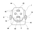
- the thermal decomposition unit 4 includes a link 41, a support 42, and a lever 43.
- the link 41 is a heat sensitive body operated by the heat of fire, and is formed by joining two thin metal plates 44 with a low melting point alloy.
- the low melting point alloy one having a melting point in the range of 60 to 200 ° C. is used, and a low melting point alloy having a melting point of 72 ° C. or 96 ° C. is generally used.
- the two substantially square metal plates 44 have a hole 45 at one end, and a U-shaped absence portion 46 at the other end.
- the two metal plates 44 are joined by a low melting point alloy in a state in which the end on the side where the lacked portion 46 is installed is overlapped. At this time, the missing portion 46 of the other metal plate 44 is superimposed on the position of the hole 45 of the one metal plate 44.
- the support 42 and the lever 43 are respectively inserted into the two holes 45 of the link 41 after joining.
- the column 42 is a strip, one end of which is engaged with the disc 32 of the valve 3 installed at the outlet of the nozzle 12 and the other end is engaged with the tip of the lever 43. As described above, the hole 45 of the link 41 is inserted through the support 42. A projection 47 is installed in the middle of the column 42, and the link 41 is locked in a groove 47A installed in the vicinity of the projection 47.
- the lever 43 is configured by bending an elongated plate into a substantially L shape. As described above, one end of the lever 43 is inserted into the hole 45 of the link 41. The other end of the lever 43 is engaged with the column 42, and the lever 43 is provided with a groove 48 in which the tip of the column 42 is engaged.
- a recess 49 is provided on the rear side of the surface on which the groove 48 is provided.
- the recess 49 is disposed closer to the other end of the lever 43 than the groove 48.
- the impression screw 16 is in contact with the recess 49.
- the tip of the impression screw 16 presses the recess 49 of the lever 43 the lever 43 is rotated about the groove 48 in which the support column 42 is locked.
- the hole 45 of the link 41 is inserted through one end side of the lever 43 to prevent the lever 43 from rotating.
- the link 41, the support 42 and the lever 43 constituting the thermal decomposition section 4 are maintained in the engaged state.
- the impression screw 16 presses and holds the valve 3 toward the nozzle 12 via the thermal decomposition section 4.
- the shape of the portion engaged with the impression screw 16 of the lever 43 is the concave portion 49, but the shape is not limited to this and can be a projection shape.
- the tip shape of the impression screw 16 can be changed to a recess or a groove corresponding to the protrusion shape.
- the present invention is also applicable to a sprinkler head in which a glass bulb is used for the thermal decomposition section 4.
- the tip shape of the impression screw 16 may be concave so as to be able to receive the glass valve.
- All the slits 21 to 26 can have equal intervals 28 between adjacent slits on the outer periphery of the deflector 2.
- the slits 21 to 26 may be disposed on an imaginary straight line passing from the outer periphery of the deflector 2 to the central axis A of the nozzle.
- the widths of the slits 21 to 24 can all be configured the same.
- the angles ⁇ of the slits 25 and 26 may be the same. Alternatively, different angles may be used within the range of 8 to 10 °.
- the longest slit 22 is placed closest to the line C.
- the line C is provided.
- the line C may be provided adjacent to the line C, and the same effect can be obtained.
Landscapes
- Health & Medical Sciences (AREA)
- Public Health (AREA)
- Business, Economics & Management (AREA)
- Emergency Management (AREA)
- Fire-Extinguishing By Fire Departments, And Fire-Extinguishing Equipment And Control Thereof (AREA)
- Nozzles (AREA)
Abstract
【課題】 床面への散水量と壁面の濡れの両方を満足できるスプリンクラーヘッドを提供する。 【解決手段】 スプリンクラーヘッドS1は、給水配管と接続されたノズル12を内部に備えた本体1、本体1からノズル12の放水方向に延出した一対のアーム14の先端はノズル12の中心軸A上に設置した柱状のボス15に連結され、ボス15の内部は牝ネジ15Bを有しており、該牝ネジ15Bに螺合されノズル12側に先端が突出しているインプレスネジ16、ボスの先端に設置された円板状のデフレクター2の外周からノズルの中心軸に向かって刻設された複数のスリットを有しており、さらにデフレクター2の中心から外周に向かって先細りとなるテーパー付スリット25が設置されており、テーパー付スリット25はスリットの幅が一定であるストレートスリット23に隣接して設置されている。
Description
本発明は、消火用のスプリンクラーヘッドに関するものであり、特に住宅用のスプリンクラーヘッドに関する。
スプリンクラー設備は建物内に設置されており、火災の熱を感知して自動的に作動して水を撒き消火を行う。スプリンクラーヘッドは内部にノズルを有しており、ノズルは給水源に続く配管と接続されており、常時はノズルが閉じた状態にある。火災が発生して熱によりスプリンクラーヘッドが作動するとノズルが開放され、ノズルから配管内に充填された水が放出される。スプリンクラーヘッドはノズルの出口の延長上に水を四方に飛散させるデフレクターを備えており、デフレクターに衝突した水が所定の範囲に散布され火災を鎮圧・消火する。
スプリンクラー設備は商業施設や公共施設、住宅等に設置されており、設置や施工のための基準が定められている。アメリカではthe National Fire Protection Association standardsによりNFPA 13として定められおり、建物の用途に応じたスプリンクラー設備の設計および設置のための基準が定められている。住宅用スプリンクラー設備の基準はNFPA 13D、13Rがある。また住宅用スプリンクラーヘッドの基準としてUnderwriters Laboratories(UL LLC)によりUL 1626が規定されている。
住宅用スプリンクラーヘッドは、床面への散水に加えて壁面にも散水を行うようにUL 1626に定められている。壁面への散水については壁面の濡れが、天井面から床面に向かって所定の距離以下となければならない。従来の住宅用スプリンクラーヘッドとして米国特許第6516893号や米国特許第7201234号がある。
上記において床面への散水量と壁面の濡れはトレードオフの関係にある。本発明では、床面への散水量と壁面の濡れの両方を満足できるスプリンクラーヘッドを提供することを目的としている。
上記の目的を達成するために、本発明は以下のスプリンクラーヘッドを提供する。
給水配管と接続されたノズルを内部に備えた本体、本体からノズルの放水方向に延出した一対のアーム、アームの先端はノズルの中心軸上に設置した柱状のボスに連結され、ボスの内部は牝ネジを有しており、該牝ネジに螺合されノズル側に先端が突出しているインプレスネジ、ボスの先端に設置された円板状のデフレクター、デフレクターの外周からノズルの中心軸に向かって刻設された複数のスリットを有しており、さらにデフレクターの中心から外周に向かって先細りとなるテーパー付スリットが設置されており、テーパー付スリットはスリットの幅が一定であるストレートスリットに隣接して設置されているスプリンクラーヘッドである。
給水配管と接続されたノズルを内部に備えた本体、本体からノズルの放水方向に延出した一対のアーム、アームの先端はノズルの中心軸上に設置した柱状のボスに連結され、ボスの内部は牝ネジを有しており、該牝ネジに螺合されノズル側に先端が突出しているインプレスネジ、ボスの先端に設置された円板状のデフレクター、デフレクターの外周からノズルの中心軸に向かって刻設された複数のスリットを有しており、さらにデフレクターの中心から外周に向かって先細りとなるテーパー付スリットが設置されており、テーパー付スリットはスリットの幅が一定であるストレートスリットに隣接して設置されているスプリンクラーヘッドである。
上記のスプリンクラーヘッドは住宅用スプリンクラーヘッドであり、ノズルの流量と放水圧力から導かれるKファクターの値が3から5.8となっている。デフレクターには、その外周からノズルの中心軸に向かって刻設された複数のスリットを有しており、さらにデフレクターの中心から外周に向かって先細りとなるテーパー付スリットが設置されている。テーパー付スリットは、ノズル中心軸側の端が円弧状に形成されており、デフレクターの外周側の端の幅は前記円弧の直径よりも小さい。テーパー付スリットにおいて、ノズル中心軸側の端から放出される水は下向きに放出され、床面への散水量が増加する。一方、デフレクターの外周側の端から放出される水は先端に近づく程、スリットの幅が狭くなり流速が上がるので壁面方向へ飛散される。
テーパー付スリットは、飛距離の低下を抑えつつ床面への散水量を増やせる効果がある。テーパー付スリットは、ノズル中心軸側の幅とデフレクターの外周側の幅が等しいストレートスリットに隣接して設置したり、あるいは一対のアームが通過する平面に隣接して設置することができる。上記により床面への散水量と壁面の濡れをコントロール可能となる。
テーパー付スリットの角度は8°~10°であり、これより角度が小さくなると上記の効果が得られない。逆に角度が大きすぎるとデフレクターの外周側の端から放出される水の勢いを減衰させてしまい壁面方向の飛距離が短くなる。
これに加えて、デフレクターおよびデフレクターが設置されたボス、ボスに設置されるインプレスネジの形状により乱流の発生を防止できる。より具体的に説明すると、ノズルから放出された水が最初に衝突するインプレスネジの先端およびインプレスネジとボスの境界部分において乱流が発生しにくい構成にすることで、散水パターンのコントロールが容易になる。
インプレスネジの先端はノズル側に突出しており、その形状は尖っている。これにより水流の抵抗が少なくなるとともに、先端に衝突した水を四方へ均一に分配する効果がある。インプレスネジの先端からボス側にかけては斜面となっており水流は斜面に沿って流れる。斜面に沿った延長線はボスの外周端の曲面と近接または接しており水流は斜面からボス外周端の曲面に沿ってスムーズに流れる。そしてボスの外周を通過してデフレクターの平面に到達した水流は、デフレクターの外周に設置されたスリットを通過して床面に向かって飛散する。あるいはデフレクターの外周まで到達して壁面に向かって飛散する。
このとき、一対のアームを通過する平面と垂直に交差し、且つノズルの中心軸を通過する線の方向は、アームによって水流が妨げられる影響が最も少ない位置であり、水流を妨げるものが無く流れがスムーズである。そのため水の勢いが強く、より遠くまで水が飛散するので壁面に対しては規定の濡れ高さを超える散水量を得ることができる。しかしその一方で、スプリンクラーヘッド直下の近距離範囲の散水量が不足する傾向がある。これに対して、この位置のスリットを他のスリットよりも長くして水流を床面に導いて近距離範囲の散水量を増やすことができる。これにより床面に対して均一な散水が可能となり壁面に対しても所望の濡れ高さを得ることができる。
以上説明したように、本発明によれば床面への散水量と壁面の濡れの両方を満足できるスプリンクラーヘッドを実現できる。さらにインプレスネジの先端とボスにおいて乱流の発生を抑制することで、乱流の発生を防止している。さらに上記構成のスプリンクラーヘッドによれば、UL 1626に規定されている散水試験および消火試験を、最も少ない流量でクリアできるスプリンクラーヘッドを実現できる。
図1および図2に示す本発明のスプリンクラーヘッドS1は、本体1、デフレクター2、弁3、感熱分解部4から構成される。
本体1は中空状をしており、外部は天井裏の配管と接続するための牡ネジ11が設けられ、内部はノズル12となっている。ノズル12のサイズは、ノズル12の流量と放水圧力から導かれるKファクターの値が3から5.8の範囲にあり、本実施形態ではKファクターの値が4.9である。配管と接続される牡ネジ11のサイズはNPT1/2またはR1/2とする。
ノズル12の出口付近には、略矩形をしたベース13が設置され、ベース13からノズル12の放水方向に伸びる一対のアーム14が設置されている。アーム14はノズルの中心軸Aと略平行に伸びた直線部14Aと、直線部14Aの端からノズル12の中心軸Aに設置されたボス15に連結される交差部14Bをと備えている。図3に示すように交差部14Bは直線部14Aよりも細く、断面形状は楕円形をしている。
ボス15はテーパーが付された円柱状で、その先端にはデフレクター2が設置されており、デフレクター2と接する側のボス15の直径D1は9~10mmとなっている。ボス15のノズル12側の直径は、デフレクター2側の直径D1よりも小径である。ボス15のノズル12側の外周端15Aは曲面形状であり、曲面の半径は1mm~3mmの範囲とし、本実施形態では2mmとしている。
ボス15の内部には牝ネジ15Bが設置されており、インプレスネジ16が螺入される。インプレスネジ16の先端16Aは尖っており、斜面16Bを備えている。先端16Aはノズル12と対向しており、斜面16Bの角度αは80°~100°の範囲が好ましく本実施形態では90°となっている。先端16Aの頂点は球面状となっており、球面半径は2mm以下が好ましく本実施形態では1mm以下としている。
インプレスネジ16は感熱分解部4を介して弁3をノズル12側に押圧する機能を有する。図3において、インプレスネジ16の先端16Aの斜面16Bに沿った延長線16Cはボス15の外周端15Aの曲面に対して近接または接しており、先端16Aの表面に沿って流れた水が外周端15Aを通過する際に流れの妨げとならず、乱流の発生を防いでいる。このとき、インプレスネジ16の斜面16Bとボス15のノズル12側の端面との間隔aは2mm以下とし、より好ましくは1mm以下とする。これ以上間隔が広がると乱流が発生する可能性が大きくなる。
図4に示すデフレクター2は円板形状をしており、その外周径は28~32mmの範囲とし、本実施形態では30mmである。デフレクター2の周縁には複数のスリットが設置されている。スリットはデフレクター2の周縁から中心側に向かって形成される。
図4において、破線で示すアーム14は直線B上に配置されている。直線Bは一対のアーム14を通過する平面を表しており、直線Bと垂直に交差し、且つ中心軸Aを通過する線Cの線上にスリット22(第3ストレートスリット)が設置されている。スリット22は、他のスリットと比較して最も長いスリットである。スリット22に隣接してスリット21が設置されている。スリット21、22はスリットの幅が一定な「ストレートスリット」であり、ノズル中心軸側の幅とデフレクターの外周側の幅が等しい。
一対のアーム14が通過する直線B上にはスリット23が刻設されており、中心軸Aを軸として直線Bを45°回転させた位置には最も短いスリット24が刻設されている。スリット23に隣接してテーパー付スリット25が刻設されている。また、スリット24に隣接してテーパー付スリット26が刻設されている。
ストレートスリットであるスリット21~24と、テーパー付スリット25、26を合わせたスリットの総数は16~28個の範囲とし、本実施形態では24個としている。スリット21~24の幅Wは、1~2mmの範囲に設定される。デフレクター2は、線Bに対して対称形状であり、さらに線Cに対して対称形状である。
スリット21~24は、ノズルの中心軸A側の端が円弧状であり、該円弧状の端からデフレクターの外周側の端まで幅が一定なスリットが形成されている。円弧の直径寸法は前述のスリット21~24の幅Wと同じである。またスリットの幅は、アーム14の交差部14Bの幅よりも小さい。
テーパー付スリット25、26はノズルの中心軸A側の端が円弧状であり、円弧の直径dは1.5~2mmとなっている。円弧の直径dはアーム14の交差部14Bの幅よりも小さい。テーパー付スリット25、26において、デフレクター2の外周側の端の幅W1は1~1.6mmであり、スリットの角度αは8°~10°である。なお、円弧の直径dは外周側の端の幅W1よりも大きい。テーパー付スリット25、26の形状は滴型をしており、円弧部分とテーパー部分の境には凹凸が無く滑らかになっている。
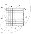
図5に示すスプリンクラーヘッドS1と散水試験設備との位置関係において、スプリンクラーヘッドS1は縦横に隙間無く並べられた採水マスMの角の位置の天井に設置される。図中の一点鎖線は、採水マスMに隣接した位置に設置された壁面を示す。図5において矢印X方向にアーム14が配置され、矢印Y方向にスリット22が配置される。UL1626では1つのマスMに対して所定の水量以上を確保する必要がある。この試験設備ではスプリンクラーヘッドS1の防護エリアの1/4について散水量が測定できる。散水パターンはデフレクター2の形状を反映して略円形となり、理想的には図5に破線で示す1/4の円の中にある全ての採水マスに均一に水が散布されることが好ましい。
しかしながら、アーム14がノズル12から放出された水流の妨げとなり、矢印X方向への水の飛距離はY方向よりも短くなる。逆にY方向はスプリンクラーヘッドS1から離れた領域Y1への散水量が多く、手前の領域Y2への散水量が少ない傾向になるが、スリット22の長さを調整することで領域Y1への散水量を減らし、領域Y2への散水量を増やすことができ、水が散水マス全体に略均一に散布される。これにより領域Y1、Y2への散水量を任意にコントロールできる。
また、アーム14に隣接して配置されたテーパー付スリット25が、アーム14方向(図中、矢印X方向)の床面散水用を増やしている。具体的に説明すると、アーム14がノズル12から放出された水流の妨げとなりアーム14方向の散水量が不足する傾向にあるが、テーパー付スリット25により床面および壁面への散水量を補っている。2つのテーパー付スリット25の間に設置されたスリット23の長さは、テーパー付スリット25よりも長い。
テーパー付スリット26は、スリット24に隣接して配置されている。スリット24はスプリンクラーヘッドS1から最も遠い領域Y3の方向に設置されており、スリット24はその長さを抑えて散水飛距離を伸ばして壁面まで水が到達できるように構成している。そのため床面への散水量が不足する傾向にあるが、テーパー付スリット26によって飛距離を落とさずに領域Y3の床面への散水量を確保している。スリット24の長さはテーパー付スリット26よりも短い。
弁3は平時においてノズル12の出口を塞いでいる。弁3はバルブキャップ31、ディスク32、皿バネ33から構成されている。バルブキャップ31は、筒状をしており一端側は球状の底部31Aとなっている。他端側は拡径されており、段31Bが設置されている。
段31Bの内周側には円盤状のディスク32が載置される。ディスク32は中心に凹み32Aを有しており、凹み32Aには感熱分解部3の支柱42の一端と係合される。
段31Bの外周側には皿バネ33が係止される。皿バネ33はバルブキャップ31の底部31Aから挿通される。皿バネ33の表面はフッ素樹脂により覆われている。皿バネ33の外周縁はノズル12の出口端に配置され、皿バネ33はインプレスネジ16をボス15の牝ネジ15Bに螺入すると感熱分解部4を介して押圧され弾性変形により潰れた形状になる。その際、フッ素樹脂がシール材の役目をしてノズル12を封止する。
感熱分解部4はリンク41、支柱42、レバー43から構成される。リンク41は火災の熱により作動する感熱体であり、2枚の薄い金属板44を低融点合金で接合して構成されている。低融点合金は60~200℃の範囲内に融点を持つものを使用しており、融点が72℃や96℃の低融点合金が一般的に使用されている。
略四角形をした2枚の金属板44は、一方の端に穴45を有しており、他方の端にはコ字型の欠如部46が設置されている。2枚の金属板44は、欠如部46が設置された側の端を重ねた状態で低融点合金により接合されている。その際、一方の金属板44の穴45の位置には、他方の金属板44の欠如部46が重ね合わされる。接合後のリンク41の2つの穴45には、それぞれ支柱42とレバー43が挿通される。
支柱42は短冊型であり、一端はノズル12の出口に設置された弁3のディスク32と係合され、他端はレバー43の先端に係合される。前述のように支柱42にはリンク41の穴45が挿通されている。支柱42の中間には突起47が設置されており、突起47の付近に設置された溝47Aにリンク41を係止している。
レバー43は細長い板を略L字型に屈曲させて構成している。前述のようにレバー43の一端側はリンク41の穴45に挿通されている。レバー43の他端側は支柱42と係合しており、レバー43には支柱42の先端が係合される溝48が設置されている。
溝48が設置された面の裏側の面には、凹部49が設置されている。凹部49は溝48よりもレバー43の他端よりに設置される。凹部49にはインプレスネジ16が接触している。インプレスネジ16の先端がレバー43の凹部49を押圧すると、レバー43は支柱42が係止されている溝48を支点として回転する力が作用する。しかしながらレバー43の一端側にはリンク41の穴45が挿通されており、レバー43の回転を阻止している。これにより感熱分解部4を構成するリンク41、支柱42、レバー43は係合状態を維持している。またインプレスネジ16は感熱分解部4を介して弁3をノズル12側に押圧保持している。
火災時において、リンク41の低融点合金が溶融すると、一方の金属板44が上記のレバー43の回転によってもう一方の金属板44から引き剥がされる。これにより感熱分解部4の係合状態は解除され、リンク41、支柱42、レバー43の係合が外れるとともに支柱42によって支えられていた弁3はノズル12から離れて脱落し、ノズル12が開放される。
以上、本発明の実施形態について説明したが、これ以外の構造、作用を以下に記載する。
先に説明した実施形態において、レバー43のインプレスネジ16と係合する箇所の形状は凹部49としたが、これに限らず突起形状にすることができる。その際、インプレスネジ16の先端形状は前記突起形状に対応する凹みや溝に変更可能である。
また、感熱分解部4にグラスバルブを用いたスプリンクラーヘッドにも適用可能である。その際、インプレスネジ16の先端形状はグラスバルブを受容可能なように凹形状にしてもよい。
全てのスリット21~26は、デフレクター2の外周上において隣接するスリットとの間隔28を等しく構成できる。スリット21~26はデフレクター2の外周からノズルの中心軸Aを通過する仮想直線上に配置してもよい。スリット21~24の幅は全て同一に構成可能である。スリット25、26の角度αは同一としてもよい。あるいは8~10°の範囲内であれば異なる角度にしてもよい。
最も長いスリット22は、線Cに対して最も近い位置に設置される。上記の実施形態では線C上に設置したが、線Cに隣接して設けることも可能であり同様の効果を得ることができる。
S1 スプリンクラーヘッド
1 本体
2 デフレクター
3 弁
4 感熱分解部
12 ノズル
14 アーム
15 ボス
15A ボスの外周端
16 インプレスネジ
16B 斜面
21、23、24 スリット
22 スリット(第1のスリット)
25、26 テーパー付スリット
31 バルブキャップ
32 ディスク
33 皿バネ
41 リンク
42 支柱
43 レバー
1 本体
2 デフレクター
3 弁
4 感熱分解部
12 ノズル
14 アーム
15 ボス
15A ボスの外周端
16 インプレスネジ
16B 斜面
21、23、24 スリット
22 スリット(第1のスリット)
25、26 テーパー付スリット
31 バルブキャップ
32 ディスク
33 皿バネ
41 リンク
42 支柱
43 レバー
Claims (17)
- 給水配管と接続されたノズルを内部に備えた本体、
本体からノズルの放水方向に延出した一対のアーム、
アームの先端はノズルの中心軸上に設置した柱状のボスに連結され、
ボスの内部は牝ネジを有しており、該牝ネジに螺合されノズル側に先端が突出しているインプレスネジ、
ボスの先端に設置された円板状のデフレクター、
デフレクターの外周からノズルの中心軸に向かって刻設された複数のスリットを有しており、
さらにデフレクターの中心から外周に向かって先細りとなるテーパー付スリットが設置されており、テーパー付スリットはスリットの幅が一定であるストレートスリットに隣接して設置されていることを特徴とするスプリンクラーヘッド。 - ストレートスリットの両隣にテーパー付スリットが設置されている請求項1記載のスプリンクラーヘッド。
- 給水配管と接続されたノズルを内部に備えた本体、
本体からノズルの放水方向に延出した一対のアーム、
アームの先端はノズルの中心軸上に設置した柱状のボスに連結され、
ボスの内部は牝ネジを有しており、該牝ネジに螺合されノズル側に先端が突出しているインプレスネジ、
ボスの先端に設置された円板状のデフレクター、
デフレクターの外周からノズルの中心軸に向かって刻設された複数のスリットを有しており、
さらにデフレクターの中心から外周に向かって先細りとなるテーパー付スリットが設置されており、テーパー付スリットは、一対のアームが通過する平面に隣接して設置されることを特徴とするスプリンクラーヘッド。 - スリットの幅が一定である第1ストレートスリットは、一対のアームが通過する平面上に設置されており、第1ストレートスリットに隣接してテーパー付スリットが設置されている請求項1~請求項3何れか1項記載のスプリンクラーヘッド。
- 第1ストレートスリットは、隣接するテーパー付スリットよりも長い請求項4記載のスプリンクラーヘッド。
- 給水配管と接続されたノズルを内部に備えた本体、
本体からノズルの放水方向に延出した一対のアーム、
アームの先端はノズルの中心軸上に設置した柱状のボスに連結され、
ボスの内部は牝ネジを有しており、該牝ネジに螺合されノズル側に先端が突出しているインプレスネジ、
ボスの先端に設置された円板状のデフレクター、
デフレクターの外周からノズルの中心軸に向かって刻設された複数のスリットを有しており、
さらにデフレクターの中心から外周に向かって先細りとなるテーパー付スリットが設置されており
スリットの幅が一定である第2ストレートスリットは、一対のアームが通過する平面に対してノズルの中心軸を軸として45°回転した位置に設置されており、第2ストレートスリットに隣接してテーパー付スリットが設置されていることを特徴とするスプリンクラーヘッド。 - 第2ストレートスリットは、隣接するテーパー付スリットよりも短い請求項6記載のスプリンクラーヘッド。
- テーパー付スリットは、ノズルの中心軸側の端が円弧状であり、デフレクターの外周側の端の幅は前記円弧の直径よりも小さい請求項1~請求項7何れか1項記載のスプリンクラーヘッド。
- テーパー付スリットの角度は8°~10°である請求項1~請求項8何れか1項記載のスプリンクラーヘッド。
- 前記円弧の直径はアームの幅よりも小さい請求項1~請求項9何れか1項記載のスプリンクラーヘッド。
- ボスのノズル側の外周端は曲面形状となっており、インプレスネジの先端形状に沿った延長線が前記曲面と近接または接する請求項1~請求項10何れか1項記載のスプリンクラーヘッド。
- インプレスネジ先端の斜面の角度が100°~80°である請求項1~請求項11何れか1項記載のスプリンクラーヘッド。
- インプレスネジの先端は尖っており、その頂点は曲面状であり曲面半径は2mm以下である請求項12記載のスプリンクラーヘッド。
- ボスのノズル側の外周端が曲面状となっている請求項1~請求項13何れか1項記載のスプリンクラーヘッド。
- ボスのノズル側の外周端の曲面半径は1mm~3mmである請求項14記載のスプリンクラーヘッド
- ノズルの流量と放水圧力から導かれるKファクターの値が3~5.8である請求項1~請求項15何れか1項記載のスプリンクラーヘッド。
- 一対のアームが通過する平面と垂直に交差し、且つノズルの中心軸を通過する線に対して最も近い位置に設けた第3ストレートスリットは、他のスリットと比較して最も長い請求項1~請求項16何れか1項記載のスプリンクラーヘッド。
Priority Applications (4)
| Application Number | Priority Date | Filing Date | Title |
|---|---|---|---|
| JP2019560032A JPWO2019123711A1 (ja) | 2017-12-20 | 2018-08-09 | スプリンクラーヘッド |
| CN201880078040.4A CN111432894A (zh) | 2017-12-20 | 2018-08-09 | 喷洒头 |
| US16/772,649 US20210094051A1 (en) | 2017-12-20 | 2018-08-09 | Sprinkler Head |
| TW107142440A TW201932160A (zh) | 2017-12-20 | 2018-11-28 | 灑水頭 |
Applications Claiming Priority (2)
| Application Number | Priority Date | Filing Date | Title |
|---|---|---|---|
| JP2017-243322 | 2017-12-20 | ||
| JP2017243322 | 2017-12-20 |
Publications (1)
| Publication Number | Publication Date |
|---|---|
| WO2019123711A1 true WO2019123711A1 (ja) | 2019-06-27 |
Family
ID=66994536
Family Applications (1)
| Application Number | Title | Priority Date | Filing Date |
|---|---|---|---|
| PCT/JP2018/029863 Ceased WO2019123711A1 (ja) | 2017-12-20 | 2018-08-09 | スプリンクラーヘッド |
Country Status (5)
| Country | Link |
|---|---|
| US (1) | US20210094051A1 (ja) |
| JP (1) | JPWO2019123711A1 (ja) |
| CN (1) | CN111432894A (ja) |
| TW (1) | TW201932160A (ja) |
| WO (1) | WO2019123711A1 (ja) |
Families Citing this family (6)
| Publication number | Priority date | Publication date | Assignee | Title |
|---|---|---|---|---|
| PE20190531A1 (es) | 2016-09-09 | 2019-04-11 | Victaulic Co Of America | Rociador y deflector de extincion de incendios |
| US11324980B2 (en) * | 2018-02-05 | 2022-05-10 | Senju Sprinkler Co., Ltd. | Sprinkler head |
| WO2019173067A1 (en) * | 2018-03-08 | 2019-09-12 | Victaulic Company | Fire suppression sprinkler and deflector |
| TWI859376B (zh) * | 2019-12-24 | 2024-10-21 | 日商千住撒水股份有限公司 | 灑水頭 |
| USD991399S1 (en) | 2021-05-06 | 2023-07-04 | Senju Sprinkler Co., Ltd. | Deflector for sprinkler head |
| CN114768155B (zh) * | 2022-05-13 | 2023-09-12 | 福建闽山消防有限公司 | 一种自调节喷水量的消防喷头 |
Citations (8)
| Publication number | Priority date | Publication date | Assignee | Title |
|---|---|---|---|---|
| JPH1015108A (ja) * | 1996-07-03 | 1998-01-20 | Nohmi Bosai Ltd | スプリンクラーヘッド |
| JP2001046544A (ja) * | 1999-08-11 | 2001-02-20 | Nohmi Bosai Ltd | スプリンクラヘッド |
| US20070246232A1 (en) * | 2006-04-20 | 2007-10-25 | The Reliable Automatic Sprinkler Co., Inc. | Extended coverage, storage, automatic fire protection sprinkler |
| US20090126950A1 (en) * | 2005-06-03 | 2009-05-21 | Tyco Fire Products Lp | Residential Flat Plate Concealed Sprinkler |
| US20100276164A1 (en) * | 2009-04-29 | 2010-11-04 | The Viking Corporation | Fire Protection Sprinkler |
| JP2012080961A (ja) * | 2010-10-07 | 2012-04-26 | Senju Sprinkler Kk | スプリンクラーヘッド |
| WO2013105241A1 (ja) * | 2011-12-01 | 2013-07-18 | 千住スプリンクラー株式会社 | スプリンクラーヘッド |
| US9717937B2 (en) * | 2012-09-21 | 2017-08-01 | Tyco Fire Products Lp | Sprinkler deflector |
-
2018
- 2018-08-09 CN CN201880078040.4A patent/CN111432894A/zh active Pending
- 2018-08-09 JP JP2019560032A patent/JPWO2019123711A1/ja active Pending
- 2018-08-09 WO PCT/JP2018/029863 patent/WO2019123711A1/ja not_active Ceased
- 2018-08-09 US US16/772,649 patent/US20210094051A1/en not_active Abandoned
- 2018-11-28 TW TW107142440A patent/TW201932160A/zh unknown
Patent Citations (8)
| Publication number | Priority date | Publication date | Assignee | Title |
|---|---|---|---|---|
| JPH1015108A (ja) * | 1996-07-03 | 1998-01-20 | Nohmi Bosai Ltd | スプリンクラーヘッド |
| JP2001046544A (ja) * | 1999-08-11 | 2001-02-20 | Nohmi Bosai Ltd | スプリンクラヘッド |
| US20090126950A1 (en) * | 2005-06-03 | 2009-05-21 | Tyco Fire Products Lp | Residential Flat Plate Concealed Sprinkler |
| US20070246232A1 (en) * | 2006-04-20 | 2007-10-25 | The Reliable Automatic Sprinkler Co., Inc. | Extended coverage, storage, automatic fire protection sprinkler |
| US20100276164A1 (en) * | 2009-04-29 | 2010-11-04 | The Viking Corporation | Fire Protection Sprinkler |
| JP2012080961A (ja) * | 2010-10-07 | 2012-04-26 | Senju Sprinkler Kk | スプリンクラーヘッド |
| WO2013105241A1 (ja) * | 2011-12-01 | 2013-07-18 | 千住スプリンクラー株式会社 | スプリンクラーヘッド |
| US9717937B2 (en) * | 2012-09-21 | 2017-08-01 | Tyco Fire Products Lp | Sprinkler deflector |
Also Published As
| Publication number | Publication date |
|---|---|
| CN111432894A (zh) | 2020-07-17 |
| TW201932160A (zh) | 2019-08-16 |
| JPWO2019123711A1 (ja) | 2020-12-10 |
| US20210094051A1 (en) | 2021-04-01 |
Similar Documents
| Publication | Publication Date | Title |
|---|---|---|
| WO2019123711A1 (ja) | スプリンクラーヘッド | |
| EP2012880B1 (en) | Extended coverage, storage, automatic fire protection sprinkler | |
| US8172001B2 (en) | Pendent residential fire protection sprinklers | |
| CA2663780A1 (en) | Extended coverage horizontal sidewall sprinkler | |
| JP7229561B2 (ja) | スプリンクラーヘッド | |
| JP6934259B2 (ja) | スプリンクラーヘッド | |
| JP7241407B2 (ja) | スプリンクラーヘッド | |
| JP7066171B2 (ja) | スプリンクラーヘッド | |
| WO2022167858A1 (en) | Sprinkler frame support bridge | |
| US11511144B2 (en) | Sprinkler head | |
| JP2006191961A (ja) | 側壁型スプリンクラーヘッド | |
| JP4768295B2 (ja) | 消火ヘッド | |
| US20250090882A1 (en) | Sprinkler frame support bridge | |
| WO2020225948A1 (ja) | スプリンクラーヘッド | |
| WO2023195046A1 (ja) | スプリンクラーヘッド | |
| HK40006970B (zh) | 灭火喷头及偏转器 | |
| HK1128436B (en) | Extended coverage, storage, automatic fire protection sprinkler | |
| HK1128436A (en) | Extended coverage, storage, automatic fire protection sprinkler | |
| HK1128437B (en) | Extended coverage horizontal sidewall sprinkler |
Legal Events
| Date | Code | Title | Description |
|---|---|---|---|
| 121 | Ep: the epo has been informed by wipo that ep was designated in this application |
Ref document number: 18892914 Country of ref document: EP Kind code of ref document: A1 |
|
| ENP | Entry into the national phase |
Ref document number: 2019560032 Country of ref document: JP Kind code of ref document: A |
|
| NENP | Non-entry into the national phase |
Ref country code: DE |
|
| 122 | Ep: pct application non-entry in european phase |
Ref document number: 18892914 Country of ref document: EP Kind code of ref document: A1 |