WO2019123711A1 - Tête de gicleur - Google Patents
Tête de gicleur Download PDFInfo
- Publication number
- WO2019123711A1 WO2019123711A1 PCT/JP2018/029863 JP2018029863W WO2019123711A1 WO 2019123711 A1 WO2019123711 A1 WO 2019123711A1 JP 2018029863 W JP2018029863 W JP 2018029863W WO 2019123711 A1 WO2019123711 A1 WO 2019123711A1
- Authority
- WO
- WIPO (PCT)
- Prior art keywords
- nozzle
- slit
- sprinkler head
- boss
- deflector
- Prior art date
- Legal status (The legal status is an assumption and is not a legal conclusion. Google has not performed a legal analysis and makes no representation as to the accuracy of the status listed.)
- Ceased
Links
Images


Classifications
-
- A—HUMAN NECESSITIES
- A62—LIFE-SAVING; FIRE-FIGHTING
- A62C—FIRE-FIGHTING
- A62C37/00—Control of fire-fighting equipment
- A62C37/08—Control of fire-fighting equipment comprising an outlet device containing a sensor, or itself being the sensor, i.e. self-contained sprinklers
- A62C37/10—Releasing means, e.g. electrically released
- A62C37/11—Releasing means, e.g. electrically released heat-sensitive
- A62C37/12—Releasing means, e.g. electrically released heat-sensitive with fusible links
-
- B—PERFORMING OPERATIONS; TRANSPORTING
- B05—SPRAYING OR ATOMISING IN GENERAL; APPLYING FLUENT MATERIALS TO SURFACES, IN GENERAL
- B05B—SPRAYING APPARATUS; ATOMISING APPARATUS; NOZZLES
- B05B1/00—Nozzles, spray heads or other outlets, with or without auxiliary devices such as valves, heating means
- B05B1/26—Nozzles, spray heads or other outlets, with or without auxiliary devices such as valves, heating means with means for mechanically breaking-up or deflecting the jet after discharge, e.g. with fixed deflectors; Breaking-up the discharged liquid or other fluent material by impinging jets
- B05B1/262—Nozzles, spray heads or other outlets, with or without auxiliary devices such as valves, heating means with means for mechanically breaking-up or deflecting the jet after discharge, e.g. with fixed deflectors; Breaking-up the discharged liquid or other fluent material by impinging jets with fixed deflectors
- B05B1/265—Nozzles, spray heads or other outlets, with or without auxiliary devices such as valves, heating means with means for mechanically breaking-up or deflecting the jet after discharge, e.g. with fixed deflectors; Breaking-up the discharged liquid or other fluent material by impinging jets with fixed deflectors the liquid or other fluent material being symmetrically deflected about the axis of the nozzle
Definitions
- the present invention relates to a sprinkler head for fire extinguishing, and more particularly to a sprinkler head for residential use.
- the sprinkler system is installed in the building and senses the heat of the fire and operates automatically to fire water and extinguish it.
- the sprinkler head has a nozzle inside, and the nozzle is connected to the pipe leading to the water supply source, and the nozzle is always in a closed state.
- the nozzle is opened, and water filled in the pipe is released from the nozzle.
- the sprinkler head is equipped with a deflector that splashes water in all directions on the extension of the nozzle outlet, and the water that has collided with the deflector is sprayed in a predetermined area to suppress and extinguish the fire.
- NFPA 13 National Fire Protection Association
- NFPA 13D The standard for residential sprinkler equipment
- UL 1626 The standard for a residential sprinkler head.
- Residential sprinkler heads are defined in UL 1626 to spray water to the walls as well as to the floor. For water sprinkling on the wall surface, the wall surface must be wet from the ceiling surface to the floor surface within a predetermined distance or less.
- U.S. Pat. No. 6,516,893 and U.S. Pat. No. 720,1234 as conventional residential sprinkler heads.
- An object of the present invention is to provide a sprinkler head which can satisfy both the amount of water sprinkling on the floor and the wetting of the wall surface.
- the present invention provides the following sprinkler head.
- a main body internally equipped with a nozzle connected to a water supply pipe, a pair of arms extending from the main body in the direction of water discharge from the main body, the tip of the arm is connected to a columnar boss installed on the central axis of the nozzle
- the screw has an eyebrow screw and is screwed into the eyebrow screw, and has an impression screw whose tip protrudes on the nozzle side, a disc-like deflector installed at the tip of a boss, and the outer circumference of the deflector toward the central axis of the nozzle It has a plurality of slits that are engraved, and a tapered slit that is tapered from the center of the deflector toward the outer periphery is installed, and the tapered slit is adjacent to a straight slit whose slit width is constant. It is a sprinkler head that has been installed.
- the sprinkler head described above is a residential sprinkler head, and the value of the K factor derived from the flow rate of the nozzle and the discharge pressure is 3 to 5.8.
- the deflector has a plurality of slits cut from its outer periphery toward the central axis of the nozzle, and a tapered slit is provided which tapers from the center of the deflector toward the outer periphery.
- the end on the nozzle center axis side is formed in an arc shape, and the width of the outer end of the deflector is smaller than the diameter of the arc.
- the water discharged from the end on the nozzle central axis side is discharged downward, and the amount of water sprinkling to the floor increases.
- the water discharged from the end on the outer peripheral side of the deflector is scattered toward the wall surface as the slit width narrows and the flow velocity increases as it approaches the tip.
- the tapered slit has an effect of increasing the amount of water sprinkling on the floor surface while suppressing a decrease in the flight distance.
- the tapered slit may be installed adjacent to a straight slit having the same width on the nozzle central axis side and the outer peripheral side of the deflector, or may be installed adjacent to a plane through which a pair of arms pass.
- the angle of the tapered slit is 8 ° to 10 °, and if the angle is smaller than this, the above effect can not be obtained. On the other hand, if the angle is too large, the momentum of water released from the outer peripheral end of the deflector is attenuated, and the flight distance in the wall surface direction becomes short.
- the shape of the deflector and the boss on which the deflector is installed and the shape of the impression screw installed on the boss can prevent the occurrence of the turbulent flow. More specifically, control of the water spray pattern is facilitated by the configuration in which turbulence is less likely to occur at the tip of the impact screw and the boundary between the impact screw and the boss where the water released from the nozzle first collides. Become.
- the tip of the impression screw protrudes toward the nozzle, and its shape is sharp. This reduces the resistance of the water flow and has the effect of evenly distributing the water colliding with the tip in four directions.
- From the tip of the impression screw to the boss side it is a slope, and the water flows along the slope.
- the extension along the slope is close to or in contact with the curved surface of the outer peripheral end of the boss, and the water flow smoothly from the slope to the curved surface of the outer peripheral end of the boss.
- the water flow passing through the outer periphery of the boss and reaching the plane of the deflector passes through the slit provided on the outer periphery of the deflector and scatters toward the floor surface. Alternatively, it reaches the outer periphery of the deflector and scatters toward the wall surface.
- the direction of the line perpendicular to the plane passing through the pair of arms and passing through the central axis of the nozzle is the position where the influence of the water flow by the arms is the least affected, and there is nothing obstructing the water flow Is smooth. Therefore, the momentum of the water is strong, and the water scatters to a further distance, so that it is possible to obtain the amount of water sprinkling exceeding the specified wet height to the wall surface.
- the amount of water spray in the short distance range immediately below the sprinkler head to be insufficient.
- the slit at this position can be made longer than the other slits to guide the water flow to the floor surface to increase the amount of water spray in the short range.
- uniform watering can be performed on the floor surface, and a desired wet height can be obtained on the wall surface.
- the present invention it is possible to realize a sprinkler head capable of satisfying both the amount of water sprinkling on the floor surface and the wetting of the wall surface. Furthermore, the occurrence of turbulent flow is prevented by suppressing the occurrence of turbulent flow at the tip of the impression screw and the boss. Furthermore, according to the sprinkler head configured as described above, it is possible to realize a sprinkler head that can clear the water spray test and the extinguishment test defined in UL 1626 with the smallest flow rate.
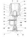
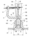
- the sprinkler head S1 of the present invention shown in FIGS. 1 and 2 is composed of a main body 1, a deflector 2, a valve 3 and a thermal decomposition section 4.
- the main body 1 has a hollow shape, and an exterior is provided with a set screw 11 for connecting to a piping on the ceiling and a ceiling, and the inside is a nozzle 12.
- the size of the nozzle 12 is such that the value of the K factor derived from the flow rate of the nozzle 12 and the discharge pressure is in the range of 3 to 5.8, and in the present embodiment, the value of the K factor is 4.9.
- the size of the female screw 11 connected to the piping is NPT1 / 2 or R1 / 2.
- a substantially rectangular base 13 is installed, and a pair of arms 14 extending from the base 13 in the water discharge direction of the nozzle 12 are installed.
- the arm 14 includes a straight portion 14A extending substantially in parallel with the central axis A of the nozzle, and a crossing portion 14B connected to a boss 15 installed on the central axis A of the nozzle 12 from the end of the linear portion 14A. As shown in FIG. 3, the crossing portion 14B is thinner than the straight portion 14A, and its cross-sectional shape is elliptical.
- the boss 15 has a tapered cylindrical shape, and the deflector 2 is installed at the tip of the boss 15.
- the diameter D1 of the boss 15 on the side in contact with the deflector 2 is 9 to 10 mm.
- the diameter of the boss 15 on the nozzle 12 side is smaller than the diameter D1 on the deflector 2 side.
- the outer peripheral end 15A on the nozzle 12 side of the boss 15 has a curved surface shape, and the radius of the curved surface is in the range of 1 mm to 3 mm, and is 2 mm in this embodiment.
- a tack screw 15B is installed inside the boss 15, and the impression screw 16 is screwed in.
- the tip 16A of the impression screw 16 is pointed and has a bevel 16B.
- the tip 16A faces the nozzle 12, and the angle ⁇ of the slope 16B is preferably in the range of 80 ° to 100 °, and is 90 ° in the present embodiment.
- the apex of the tip 16A is spherical, and the spherical radius is preferably 2 mm or less, and is 1 mm or less in the present embodiment.
- the impression screw 16 has a function of pressing the valve 3 toward the nozzle 12 via the thermal decomposition section 4.
- the extended line 16C along the inclined surface 16B of the tip 16A of the impression screw 16 is close to or in contact with the curved surface of the outer peripheral end 15A of the boss 15, and the water flowing along the surface of the tip 16A is the outer peripheral end It does not obstruct the flow when passing 15A and prevents the occurrence of turbulent flow.
- the distance a between the slope 16B of the impression screw 16 and the end face of the boss 15 on the nozzle 12 side is 2 mm or less, and more preferably 1 mm or less. If the interval is further expanded, the possibility of the occurrence of turbulence increases.
- the deflector 2 shown in FIG. 4 has a disk shape, and the outer diameter thereof is in the range of 28 to 32 mm, and is 30 mm in the present embodiment.
- a plurality of slits are provided at the periphery of the deflector 2. The slits are formed from the peripheral edge of the deflector 2 toward the center.
- an arm 14 indicated by a broken line is disposed on a straight line B.
- the straight line B represents a plane passing through the pair of arms 14, and a slit 22 (third straight slit) is disposed on a line C perpendicular to the straight line B and passing through the central axis A.
- the slit 22 is the longest slit as compared to other slits.
- the slit 21 is disposed adjacent to the slit 22.
- the slits 21 and 22 are “straight slits” in which the width of the slit is constant, and the width on the nozzle central axis side is equal to the width on the outer peripheral side of the deflector.
- a slit 23 is cut on the straight line B through which the pair of arms 14 pass, and the shortest slit 24 is cut at the position where the straight line B is rotated 45 ° around the central axis A.
- a tapered slit 25 is engraved adjacent to the slit 23. Further, a tapered slit 26 is engraved adjacent to the slit 24.
- the total number of slits 21 to 24, which are straight slits, and the total number of slits combined with the tapered slits 25 and 26 is in the range of 16 to 28, and is 24 in this embodiment.
- the width W of the slits 21 to 24 is set in the range of 1 to 2 mm.
- the deflector 2 has a symmetrical shape with respect to the line B and further has a symmetrical shape with respect to the line C.
- the slits 21 to 24 are arc-shaped at the end on the central axis A of the nozzle, and a slit having a constant width is formed from the arc-shaped end to the end on the outer peripheral side of the deflector.
- the diameter of the arc is the same as the width W of the slits 21 to 24 described above. Further, the width of the slit is smaller than the width of the intersection 14B of the arm 14.
- the tapered slits 25 and 26 are arc-shaped at the end on the central axis A side of the nozzle, and the diameter d of the arc is 1.5 to 2 mm.
- the diameter d of the arc is smaller than the width of the intersection 14B of the arm 14.
- the width W1 of the end on the outer peripheral side of the deflector 2 is 1 to 1.6 mm, and the slit angle ⁇ is 8 ° to 10 °.
- the diameter d of the arc is larger than the width W1 of the end on the outer peripheral side.
- the tapered slits 25 and 26 have a drop shape, and the boundary between the arc portion and the tapered portion is smooth without unevenness.
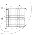
- the water spray pattern is substantially circular reflecting the shape of the deflector 2, and ideally, the water is uniformly dispersed to all the water collection mass in the circle of 1 ⁇ 4 indicated by a broken line in FIG. .
- the arm 14 obstructs the flow of water discharged from the nozzle 12, and the flight distance of water in the arrow X direction becomes shorter than the Y direction.
- the amount of water sprinkling to the area Y1 away from the sprinkler head S1 tends to be large in the Y direction, and the amount of water sprinkling to the area Y2 in the front tends to be small.
- the amount of water can be reduced and the amount of water spouted to the area Y2 can be increased, and the water is dispersed substantially uniformly throughout the water sprinkling mass. Thereby, the amount of water spray to the regions Y1 and Y2 can be controlled arbitrarily.
- the tapered slit 25 disposed adjacent to the arm 14 increases the floor surface water sprinkling direction in the direction of the arm 14 (the arrow X direction in the drawing). Specifically, although the arm 14 obstructs the water flow discharged from the nozzle 12 and the amount of water sprinkling in the direction of the arm 14 tends to be insufficient, the amount of water sprinkling on the floor surface and the wall surface is compensated by the tapered slit 25 .
- the length of the slit 23 disposed between the two tapered slits 25 is longer than that of the tapered slit 25.
- the tapered slit 26 is disposed adjacent to the slit 24.
- the slit 24 is installed in the direction of the area Y3 farthest from the sprinkler head S1, and the slit 24 is configured to reduce the length thereof to extend the spray distance and allow water to reach the wall surface. Therefore, although the amount of water sprinkling on the floor tends to be insufficient, the tapered slit 26 secures the amount of water spouting on the floor of the region Y3 without reducing the flight distance.
- the length of the slit 24 is shorter than the tapered slit 26.
- the valve 3 closes the outlet of the nozzle 12 in normal time.
- the valve 3 comprises a valve cap 31, a disc 32 and a disc spring 33.
- the valve cap 31 has a cylindrical shape, and one end side is a spherical bottom 31A. The other end side is expanded in diameter, and a step 31B is installed.
- a disc-shaped disk 32 is placed on the inner peripheral side of the step 31B.
- the disk 32 has a recess 32A at its center, and the recess 32A is engaged with one end of the support 42 of the thermal decomposition section 3.
- the disc spring 33 is locked on the outer peripheral side of the step 31B.
- the disc spring 33 is inserted from the bottom 31 A of the valve cap 31.
- the surface of the disc spring 33 is covered with a fluorine resin.
- the outer peripheral edge of the disc spring 33 is disposed at the outlet end of the nozzle 12, and the disc spring 33 is pressed through the thermosensitive decomposition part 4 when the impression screw 16 is screwed into the setscrew 15B of the boss 15 and is crushed by elastic deformation. Become.
- the fluorine resin acts as a sealing material to seal the nozzle 12.
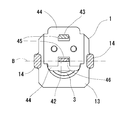
- the thermal decomposition unit 4 includes a link 41, a support 42, and a lever 43.
- the link 41 is a heat sensitive body operated by the heat of fire, and is formed by joining two thin metal plates 44 with a low melting point alloy.
- the low melting point alloy one having a melting point in the range of 60 to 200 ° C. is used, and a low melting point alloy having a melting point of 72 ° C. or 96 ° C. is generally used.
- the two substantially square metal plates 44 have a hole 45 at one end, and a U-shaped absence portion 46 at the other end.
- the two metal plates 44 are joined by a low melting point alloy in a state in which the end on the side where the lacked portion 46 is installed is overlapped. At this time, the missing portion 46 of the other metal plate 44 is superimposed on the position of the hole 45 of the one metal plate 44.
- the support 42 and the lever 43 are respectively inserted into the two holes 45 of the link 41 after joining.
- the column 42 is a strip, one end of which is engaged with the disc 32 of the valve 3 installed at the outlet of the nozzle 12 and the other end is engaged with the tip of the lever 43. As described above, the hole 45 of the link 41 is inserted through the support 42. A projection 47 is installed in the middle of the column 42, and the link 41 is locked in a groove 47A installed in the vicinity of the projection 47.
- the lever 43 is configured by bending an elongated plate into a substantially L shape. As described above, one end of the lever 43 is inserted into the hole 45 of the link 41. The other end of the lever 43 is engaged with the column 42, and the lever 43 is provided with a groove 48 in which the tip of the column 42 is engaged.
- a recess 49 is provided on the rear side of the surface on which the groove 48 is provided.
- the recess 49 is disposed closer to the other end of the lever 43 than the groove 48.
- the impression screw 16 is in contact with the recess 49.
- the tip of the impression screw 16 presses the recess 49 of the lever 43 the lever 43 is rotated about the groove 48 in which the support column 42 is locked.
- the hole 45 of the link 41 is inserted through one end side of the lever 43 to prevent the lever 43 from rotating.
- the link 41, the support 42 and the lever 43 constituting the thermal decomposition section 4 are maintained in the engaged state.
- the impression screw 16 presses and holds the valve 3 toward the nozzle 12 via the thermal decomposition section 4.
- the shape of the portion engaged with the impression screw 16 of the lever 43 is the concave portion 49, but the shape is not limited to this and can be a projection shape.
- the tip shape of the impression screw 16 can be changed to a recess or a groove corresponding to the protrusion shape.
- the present invention is also applicable to a sprinkler head in which a glass bulb is used for the thermal decomposition section 4.
- the tip shape of the impression screw 16 may be concave so as to be able to receive the glass valve.
- All the slits 21 to 26 can have equal intervals 28 between adjacent slits on the outer periphery of the deflector 2.
- the slits 21 to 26 may be disposed on an imaginary straight line passing from the outer periphery of the deflector 2 to the central axis A of the nozzle.
- the widths of the slits 21 to 24 can all be configured the same.
- the angles ⁇ of the slits 25 and 26 may be the same. Alternatively, different angles may be used within the range of 8 to 10 °.
- the longest slit 22 is placed closest to the line C.
- the line C is provided.
- the line C may be provided adjacent to the line C, and the same effect can be obtained.
Landscapes
- Health & Medical Sciences (AREA)
- Public Health (AREA)
- Business, Economics & Management (AREA)
- Emergency Management (AREA)
- Fire-Extinguishing By Fire Departments, And Fire-Extinguishing Equipment And Control Thereof (AREA)
- Nozzles (AREA)
Abstract
La présente invention concerne une tête de gicleur satisfaisante à la fois en termes de volume d'aspersion sur le sol et de mouillage de surfaces de paroi. L'invention concerne une tête de gicleur S1 qui comprend : un corps 1 comprenant une buse 12 à l'intérieur qui est reliée à une ligne d'alimentation en eau ; une vis d'empreinte 16 ; et de multiples fentes qui sont incisées vers l'axe central A de la buse 12 depuis la circonférence d'un déflecteur de type disque 2. Une paire de bras 14 s'étend à partir du corps 1 dans la direction d'évacuation de la buse 12, les extrémités distales de la paire de bras 14 sont reliées à un bossage cylindrique 15 situé sur l'axe central A de la buse 12, et un filetage interne 15B est situé à l'intérieur du bossage 15. La vis d'empreinte 16 est vissée dans le filetage interne 15B avec l'extrémité distale de la vis d'empreinte 16 faisant saillie vers la buse 12. Le déflecteur 2 est disposé sur l'extrémité distale du bossage. En outre, sur la tête de gicleur, sont formées des fentes effilées 25 qui sont effilées vers la circonférence depuis le centre du déflecteur 2 et situées en position adjacente à des fentes droites 23 ayant des largeurs uniformes.
Priority Applications (4)
| Application Number | Priority Date | Filing Date | Title |
|---|---|---|---|
| JP2019560032A JPWO2019123711A1 (ja) | 2017-12-20 | 2018-08-09 | スプリンクラーヘッド |
| CN201880078040.4A CN111432894A (zh) | 2017-12-20 | 2018-08-09 | 喷洒头 |
| US16/772,649 US20210094051A1 (en) | 2017-12-20 | 2018-08-09 | Sprinkler Head |
| TW107142440A TW201932160A (zh) | 2017-12-20 | 2018-11-28 | 灑水頭 |
Applications Claiming Priority (2)
| Application Number | Priority Date | Filing Date | Title |
|---|---|---|---|
| JP2017-243322 | 2017-12-20 | ||
| JP2017243322 | 2017-12-20 |
Publications (1)
| Publication Number | Publication Date |
|---|---|
| WO2019123711A1 true WO2019123711A1 (fr) | 2019-06-27 |
Family
ID=66994536
Family Applications (1)
| Application Number | Title | Priority Date | Filing Date |
|---|---|---|---|
| PCT/JP2018/029863 Ceased WO2019123711A1 (fr) | 2017-12-20 | 2018-08-09 | Tête de gicleur |
Country Status (5)
| Country | Link |
|---|---|
| US (1) | US20210094051A1 (fr) |
| JP (1) | JPWO2019123711A1 (fr) |
| CN (1) | CN111432894A (fr) |
| TW (1) | TW201932160A (fr) |
| WO (1) | WO2019123711A1 (fr) |
Families Citing this family (6)
| Publication number | Priority date | Publication date | Assignee | Title |
|---|---|---|---|---|
| PE20190531A1 (es) | 2016-09-09 | 2019-04-11 | Victaulic Co Of America | Rociador y deflector de extincion de incendios |
| US11324980B2 (en) * | 2018-02-05 | 2022-05-10 | Senju Sprinkler Co., Ltd. | Sprinkler head |
| WO2019173067A1 (fr) * | 2018-03-08 | 2019-09-12 | Victaulic Company | Gicleur d'incendie et déflecteur |
| TWI859376B (zh) * | 2019-12-24 | 2024-10-21 | 日商千住撒水股份有限公司 | 灑水頭 |
| USD991399S1 (en) | 2021-05-06 | 2023-07-04 | Senju Sprinkler Co., Ltd. | Deflector for sprinkler head |
| CN114768155B (zh) * | 2022-05-13 | 2023-09-12 | 福建闽山消防有限公司 | 一种自调节喷水量的消防喷头 |
Citations (8)
| Publication number | Priority date | Publication date | Assignee | Title |
|---|---|---|---|---|
| JPH1015108A (ja) * | 1996-07-03 | 1998-01-20 | Nohmi Bosai Ltd | スプリンクラーヘッド |
| JP2001046544A (ja) * | 1999-08-11 | 2001-02-20 | Nohmi Bosai Ltd | スプリンクラヘッド |
| US20070246232A1 (en) * | 2006-04-20 | 2007-10-25 | The Reliable Automatic Sprinkler Co., Inc. | Extended coverage, storage, automatic fire protection sprinkler |
| US20090126950A1 (en) * | 2005-06-03 | 2009-05-21 | Tyco Fire Products Lp | Residential Flat Plate Concealed Sprinkler |
| US20100276164A1 (en) * | 2009-04-29 | 2010-11-04 | The Viking Corporation | Fire Protection Sprinkler |
| JP2012080961A (ja) * | 2010-10-07 | 2012-04-26 | Senju Sprinkler Kk | スプリンクラーヘッド |
| WO2013105241A1 (fr) * | 2011-12-01 | 2013-07-18 | 千住スプリンクラー株式会社 | Tête d'arrosage |
| US9717937B2 (en) * | 2012-09-21 | 2017-08-01 | Tyco Fire Products Lp | Sprinkler deflector |
-
2018
- 2018-08-09 CN CN201880078040.4A patent/CN111432894A/zh active Pending
- 2018-08-09 JP JP2019560032A patent/JPWO2019123711A1/ja active Pending
- 2018-08-09 WO PCT/JP2018/029863 patent/WO2019123711A1/fr not_active Ceased
- 2018-08-09 US US16/772,649 patent/US20210094051A1/en not_active Abandoned
- 2018-11-28 TW TW107142440A patent/TW201932160A/zh unknown
Patent Citations (8)
| Publication number | Priority date | Publication date | Assignee | Title |
|---|---|---|---|---|
| JPH1015108A (ja) * | 1996-07-03 | 1998-01-20 | Nohmi Bosai Ltd | スプリンクラーヘッド |
| JP2001046544A (ja) * | 1999-08-11 | 2001-02-20 | Nohmi Bosai Ltd | スプリンクラヘッド |
| US20090126950A1 (en) * | 2005-06-03 | 2009-05-21 | Tyco Fire Products Lp | Residential Flat Plate Concealed Sprinkler |
| US20070246232A1 (en) * | 2006-04-20 | 2007-10-25 | The Reliable Automatic Sprinkler Co., Inc. | Extended coverage, storage, automatic fire protection sprinkler |
| US20100276164A1 (en) * | 2009-04-29 | 2010-11-04 | The Viking Corporation | Fire Protection Sprinkler |
| JP2012080961A (ja) * | 2010-10-07 | 2012-04-26 | Senju Sprinkler Kk | スプリンクラーヘッド |
| WO2013105241A1 (fr) * | 2011-12-01 | 2013-07-18 | 千住スプリンクラー株式会社 | Tête d'arrosage |
| US9717937B2 (en) * | 2012-09-21 | 2017-08-01 | Tyco Fire Products Lp | Sprinkler deflector |
Also Published As
| Publication number | Publication date |
|---|---|
| CN111432894A (zh) | 2020-07-17 |
| TW201932160A (zh) | 2019-08-16 |
| JPWO2019123711A1 (ja) | 2020-12-10 |
| US20210094051A1 (en) | 2021-04-01 |
Similar Documents
| Publication | Publication Date | Title |
|---|---|---|
| WO2019123711A1 (fr) | Tête de gicleur | |
| EP2012880B1 (fr) | Tete d'extincteur automatique de protection contre les incendies, a couverture accrue, destinee au domaine de l'entreposage | |
| US8172001B2 (en) | Pendent residential fire protection sprinklers | |
| CA2663780A1 (fr) | Tete d'extincteur automatique sur paroi laterale a l'horizontale et a couverture accrue | |
| JP7229561B2 (ja) | スプリンクラーヘッド | |
| JP6934259B2 (ja) | スプリンクラーヘッド | |
| JP7241407B2 (ja) | スプリンクラーヘッド | |
| JP7066171B2 (ja) | スプリンクラーヘッド | |
| WO2022167858A1 (fr) | Pont de support de cadre de gicleur | |
| US11511144B2 (en) | Sprinkler head | |
| JP2006191961A (ja) | 側壁型スプリンクラーヘッド | |
| JP4768295B2 (ja) | 消火ヘッド | |
| US20250090882A1 (en) | Sprinkler frame support bridge | |
| WO2020225948A1 (fr) | Tête de pulvérisateur | |
| WO2023195046A1 (fr) | Tête d'arroseur | |
| HK40006970B (zh) | 灭火喷头及偏转器 | |
| HK1128436B (en) | Extended coverage, storage, automatic fire protection sprinkler | |
| HK1128436A (en) | Extended coverage, storage, automatic fire protection sprinkler | |
| HK1128437B (en) | Extended coverage horizontal sidewall sprinkler |
Legal Events
| Date | Code | Title | Description |
|---|---|---|---|
| 121 | Ep: the epo has been informed by wipo that ep was designated in this application |
Ref document number: 18892914 Country of ref document: EP Kind code of ref document: A1 |
|
| ENP | Entry into the national phase |
Ref document number: 2019560032 Country of ref document: JP Kind code of ref document: A |
|
| NENP | Non-entry into the national phase |
Ref country code: DE |
|
| 122 | Ep: pct application non-entry in european phase |
Ref document number: 18892914 Country of ref document: EP Kind code of ref document: A1 |