WO2019123747A1 - Dispositif de commande électronique d'automobile et procédé de commande associé - Google Patents
Dispositif de commande électronique d'automobile et procédé de commande associé Download PDFInfo
- Publication number
- WO2019123747A1 WO2019123747A1 PCT/JP2018/034869 JP2018034869W WO2019123747A1 WO 2019123747 A1 WO2019123747 A1 WO 2019123747A1 JP 2018034869 W JP2018034869 W JP 2018034869W WO 2019123747 A1 WO2019123747 A1 WO 2019123747A1
- Authority
- WO
- WIPO (PCT)
- Prior art keywords
- data
- erase
- volatile memory
- block
- electronic control
- Prior art date
- Legal status (The legal status is an assumption and is not a legal conclusion. Google has not performed a legal analysis and makes no representation as to the accuracy of the status listed.)
- Ceased
Links
Images






Classifications
-
- B—PERFORMING OPERATIONS; TRANSPORTING
- B60—VEHICLES IN GENERAL
- B60R—VEHICLES, VEHICLE FITTINGS, OR VEHICLE PARTS, NOT OTHERWISE PROVIDED FOR
- B60R16/00—Electric or fluid circuits specially adapted for vehicles and not otherwise provided for; Arrangement of elements of electric or fluid circuits specially adapted for vehicles and not otherwise provided for
- B60R16/02—Electric or fluid circuits specially adapted for vehicles and not otherwise provided for; Arrangement of elements of electric or fluid circuits specially adapted for vehicles and not otherwise provided for electric constitutive elements
-
- G—PHYSICS
- G06—COMPUTING OR CALCULATING; COUNTING
- G06F—ELECTRIC DIGITAL DATA PROCESSING
- G06F8/00—Arrangements for software engineering
- G06F8/60—Software deployment
- G06F8/65—Updates
-
- G—PHYSICS
- G06—COMPUTING OR CALCULATING; COUNTING
- G06F—ELECTRIC DIGITAL DATA PROCESSING
- G06F8/00—Arrangements for software engineering
- G06F8/60—Software deployment
- G06F8/65—Updates
- G06F8/654—Updates using techniques specially adapted for alterable solid state memories, e.g. for EEPROM or flash memories
Definitions
- the present invention relates to an electronic control device for a vehicle and a control method thereof, and more particularly to a technology for updating control software in an ECU (Electric Control Unit) mounted on a vehicle.
- ECU Electronic Control Unit
- the present invention has been made in view of the above circumstances, and it is an object of the present invention to provide an electronic control apparatus for a vehicle capable of shortening the update time of software stored in a non-volatile memory and a control method thereof. It is in.
- the electronic control unit for a motor vehicle has a non-volatile memory capable of erasing data in erase block units and writing data in write block units identical or smaller than the erase block.
- An electronic control unit for a motor vehicle in which a control program is stored for each storage area configured in units of integral multiples of erase blocks in the nonvolatile memory, the non-volatile memory corresponding to an external rewrite request.
- a processor is provided which erases the data of a part in an erase block unit and, when writing the data in a write block unit in the non-volatile memory, comprises a processor for confirming rewriting correctness / incorrectness for each block.
- the control method of the electronic control unit for a motor vehicle is non-volatile, capable of erasing data in erase block units and writing data in write block units identical or smaller than the erase block.
- a control method of an electronic control unit for a motor vehicle having a memory and storing a control program for each storage area configured in units of integral multiples of erase blocks in the non-volatile memory, the control method according to an external rewrite request. And erase the partial data of the non-volatile memory in erase block units, and when writing the data in the non-volatile memory in write block units, check whether the rewriting is correct or not for each of the blocks. I assume.
- the control program is stored in the non-volatile memory for each storage area configured in units of integral multiples of the erase block, and the assignment of the control program corresponds to the erase block. This can be done for each control program, and the amount of data transfer can be reduced to shorten the software update time. Further, in response to an external rewrite request, a part of the storage area of the non-volatile memory is erased, and writing in this erase area in units of write blocks can reduce the size of the rewrite target area. The write time can be shortened to shorten the software update time.
- FIG. 1 is a schematic view showing a data rewriting system of an electronic control unit for a car according to a first embodiment of the present invention. It is a block diagram which shows the structural example of the electronic controller for motor vehicles in the system shown in FIG.
- FIG. 3 is a diagram showing an example of a memory configuration of a flash ROM in FIG. 2; It is a block diagram which shows the structural example of the tool in the system shown in FIG.
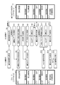
- FIG. 6 is a flowchart for explaining an example of data rewrite processing, and a diagram showing a memory configuration of storage on the tool side and a memory configuration of a flash ROM on the ECU side.
- FIG. 1 is a schematic view showing a data rewriting system of an electronic control unit for a car according to a first embodiment of the present invention.
- FIG. 3 is a diagram showing an example of a memory configuration of a flash ROM in FIG. 2;
- FIG. 6 is a flowchart for explaining an example of data rewrite processing, and
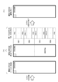
- FIG. 7 is a diagram showing states of storage, flash ROM and RAM before and during rewriting in the ENG control program to be rewritten.
- FIG. 7 is a diagram showing states of the flash ROM and the RAM during and after rewriting in the ENG control program to be rewritten.
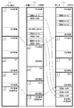
- FIG. 13 is an explanatory view showing memory configurations before and after countermeasure in comparison with each other when the capacity of the rewrite area is over.
- FIG. 10 is a flowchart for explaining another example of the data rewrite process, and a diagram showing a memory configuration of storage on the tool side and a memory configuration of a flash ROM on the ECU side. It is a flowchart for demonstrating another example of a data rewriting process following FIG. 9A. It is a schematic diagram showing a data rewriting system in an electronic control unit for a car according to a second embodiment of the present invention.
- FIG. 1 shows an example of a data rewriting system which rewrites data of an electronic control unit (ECU: Electronic Control Unit) mounted on a vehicle.
- the ECU 10 to be rewritten is detachably connected to the tool 30 via a network cable 20 such as CAN (Controller Area Network), serial communication, FlexRay (registered trademark) and Ethernet (registered trademark).
- a network cable 20 such as CAN (Controller Area Network), serial communication, FlexRay (registered trademark) and Ethernet (registered trademark).
- the operator operates the tool 30 to rewrite the ECU 10.
- the ECU 10 and the tool 30 are not limited to wired using the network cable 20, and may be connected to each other by wireless communication using a wireless transceiver.
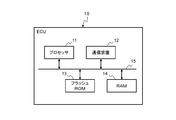
- the ECU 10 is an electronic device that controls various devices mounted on a vehicle, such as a fuel injection valve, a transmission, an electric brake system, an ABS (Antilock Brake System), a variable valve timing mechanism, and a brushless motor. It has a built-in computer. Specifically, as shown in FIG. 2, the ECU 10 includes a processor 11 such as a central processing unit (CPU), a communication device 12 for connecting to a network, a flash ROM 13 as an example of a non-volatile memory, and volatilization It has RAM (Random Access Memory) 14 as an example of sex memory, and bus 15. Here, the bus 15 mutually connects the processor 11, the communication device 12, the flash ROM 13 and the RAM 14. The communication device 12 also includes a connector (not shown) that detachably connects the network cable 20.
- a processor 11 such as a central processing unit (CPU)
- a communication device 12 for connecting to a network
- flash ROM 13 as an example of a non-volatile memory
- the storage area of the flash ROM 13 is divided into a plurality of erase blocks EB1 to EBq of a predetermined size, as shown in FIG.
- Each erase block EB1 to EBq is partitioned into a plurality of write blocks WB1, WB2,..., WBx of a predetermined size.
- the erase block defines the minimum unit for erasing data
- the write block defines the minimum unit for writing data
- the write block has the same or smaller capacity than the erase block. .
- an ENG (Engine) control program is stored in the storage area corresponding to the erase blocks EB1 to EBm of the flash ROM 13, and the surplus part is an empty area.
- Identification information for example, identification of new and old programs
- identification information for identifying each erase block is added to the start address of the erase block EB1.
- a hash value (hash value 1) is used in this example.
- the hash value is an example of identification information for comparing the identity of data, and it is preferable to adopt similar data that takes largely different values. Then, the processor 31 temporarily stores the hash value calculated from the data of the erase block EB1 in a storage medium such as a RAM in the processor 31.
- a TCU (Transmission Control Unit) control program is stored in the storage area corresponding to the erase blocks EBm + 1 to EBn, and the surplus portion is an empty area.
- Identification information for example, a hash value 2 for identifying the stored control program and the control program to be rewritten or identifying the respective erase blocks is given to the start address of the erase block EBm + 1.
- an API Application Programming Interface
- the surplus portion is an empty area.
- Identification information (for example, hash value 3) for identifying the stored control program and the control program to be rewritten or identifying the respective erase blocks is given to the top address of the erase block EBn + 1.
- a BIOS Basic Input Output System
- Identification information (for example, hash value 4) for identifying the stored control program and the control program to be rewritten or identifying the respective erasure blocks is given to the top address of the erasure block EBo + 1.
- the storage areas corresponding to the erase blocks EBp + 1 to EBq are common free areas (common areas). Identification information (for example, hash value 5) for identifying a free area or identifying each of the erase blocks is given to the top address of the erase block EBp + 1. As described above, various programs are stored in the flash ROM 13 for each storage area configured in units of integral multiples of the erase block.
- the tool 30 is an electronic device with which an operator performs data rewriting work of the ECU 10, and is configured of, for example, a personal computer.
- the tool 30 works with a processor 31 such as a CPU, a communication device 32 for connecting to a network, a storage 33 such as a hard disk drive or a solid state drive (SSD), It comprises an input / output device 34 serving as an interface to the user, and a bus 35 for interconnecting these devices.
- the communication device 32 includes a connector (not shown) for detachably connecting the network cable 20.
- the input / output device 34 also includes a display such as an LCD (Liquid Crystal Display), a keyboard, and a pointing device such as a mouse.
- the storage 33 may be, for example, storage of a NAS (Network Attached Storage) or a server connected to a network (not shown).
- the storage 33 stores rewrite data for rewriting the flash ROM 13 of the ECU 10.
- the rewrite data includes, for example, a control program for controlling various devices mounted on a vehicle, and control parameters such as constants and maps used in the control program.
- the rewrite data stored in the storage 33 is transferred to the communication device 32 through the bus 35 under the control of the processor 31 and transmitted to the ECU 10 from the connector (not shown) through the network cable 20.
- FIG. 5 shows an example of a procedure for updating a part of the control program of the flash ROM 13 of the ECU 10, the memory configuration of the storage on the tool side, and the memory configuration of the flash ROM on the ECU side.
- FIG. 6 shows the states of the storage, flash ROM and RAM before and during rewriting in the ENG control program to be rewritten.
- FIG. 7 shows the states of the flash ROM and the RAM during and after rewriting in the ENG control program to be rewritten.
- the data rewriting process is performed when the operator performs a predetermined operation in the tool 30 after the tool 30 is connected to the ECU 10 with the network cable 20.
- the ECU 10 is premised to be supplied with electric power and activated when connected to the tool 30 via the network cable 20, but may be activated by connection of another power cable.
- the storage 33 in the tool 30 has a memory configuration in which an ENG control program, a TCU control program, an API, a BIOS, and a free area are allocated as in FIG. 3.
- version 2 (Ver: 2) is granted.
- the software written in the flash ROM 13 in the ECU 10 has a memory configuration in which an ENG control program, a TCU control program, an API, a BIOS, and a free area are allocated as in FIG. Then, version 1 (Ver: 1) is assigned as identification information of the ENG control program, and version 2 (Ver: 2) is assigned as identification information to the TCU control program, API, BIOS and free space.
- FIG. 6A shows the ENG control program (Ver: 2) of the storage 33 on the tool 30 side and the ENG control program (Ver: 1) of the flash ROM 13 before rewriting on the ECU 10 side. There is free space in the surplus part.
- an identification information collation request is issued from the tool 30 to the ECU 10 (step S1), and identification information (here, software Ver: 2) stored in the storage 33 in the tool 30 and identification stored in the flash ROM 13 in the ECU 10
- the information (here, software Ver: 1) is compared by the ECU 10 (step S2). If there is a difference in the identification information, the ECU 10 makes a request to send the rewrite data to the tool 30 (step S3). As a result, the tool 30 outputs an erase request for the rewrite target (area) (step S4).
- the ECU 10 receives the deletion request from the tool 30, deletion of the rewrite target (area) is started (step S5).
- the ECU 10 notifies the tool 30 of the end of the erasing (step S6).
- write data (software Ver: 2 ENG control program) is transferred from the tool 30 to the ECU 10 (step S7), and the write data is stored in the RAM 14 (step S8).
- the ECU 10 determines whether there is a writing abnormality (step S10). If there is no difference in the identification information at step S2 and if it is determined at step S10 that "writing abnormality is not present", the ECU 10 notifies the tool 30 of writing completion (step S13), and the tool 30 completes writing When the notification is received, the writing completion is displayed on the display of the input / output device 34 to notify the worker (step S14). If there are a plurality of rewrite targets, an identification information collation request is issued for the next write target, and the process moves to the next rewrite target (step S15), and the same operation as the above-described step is repeated.
- step S10 determines whether write error has an error
- the erase block including the corresponding write block (abnormal portion) is erased (step S11).
- Rewriting is performed using the held data (step S12). During this erase and rewrite, external communication is not interrupted.
- the write data to the write blocks WBn + 1 to WBo-1 may be retransferred from the storage 33 of the tool 30 to the RAM 14 and written again.
- the ENG control program of the same version 2 as the storage 33 on the tool 30 side is written to the flash ROM 13 and updating from the old version to the new version finish.
- the tool 30 receives and monitors the busy signal output from the ECU 10 (step S16) to avoid communication timeout between the tool 30 and the ECU 10.
- the ECU 10 notifies the tool 30 of writing completion (step S13), and when the tool 30 receives the writing completion notification, the tool 30 displays it on the display of the input / output device 34 to notify the operator of writing completion (step S14). Then, if there are a plurality of rewrite targets, an identification information collation request is issued for the next write target, and the process moves to the next rewrite target (step S15), and the same operation as the above-described step is repeated.
- FIG. 8 shows a comparison of the memory configurations before and after the countermeasure when the amount of data to be written is larger than the amount of written data and the capacity of the rewrite area is over in the data rewriting process described above. ing.
- the flash ROM 13 has the same memory configuration as that shown in FIG. 3, and the case of rewriting the ENG control program will be described as an example.
- the ENG control program includes “function A call” and “function A main body”, and writes an additional ENG control program in the free space of this ENG control program. Shall be included.
- the additional ENG control program includes "function B call", "function B main body”, “function C call” and "function C main body”.
- the additional ENG control program has a larger capacity than the empty area and can not fit in the empty area, other control programs that do not need to be rewritten, for example, the TCU control program, API and BIOS must also sequentially rewrite the address and rewrite It does not.
- each control program area is used to secure the additional data capacity, but when a specific control program area overflows, (b) and (c) of FIG. As shown in), an arbitrary function call unit may be placed in the control program area, and the function body may be moved to a common free area.
- FIGS. 9A and 9B respectively show another example of the data rewriting process for updating a part of the control program of the flash ROM 13 of the ECU 10, in which a plurality of control programs are rewritten.
- the case where the ENG control program of the flash ROM 13 (the ECU 10 side) before rewriting is the old version and the case where the additional ENG control program is written in the common free space is taken as an example.
- an identification information collation request is issued from the tool 30 to the ECU 10 (step S21), and the identification information (here, software Ver: 2) stored in the storage 33 in the tool 30 and the identification stored in the flash ROM 13 in the ECU 10
- the information (here, software Ver: 1) is compared by the ECU 10 (step S22). If there is a difference in the identification information, the ECU 10 sends a request for sending the ENG control program, which is the rewrite data, to the tool 30 (step S23). As a result, the erasing request for rewriting is output from the tool 30 (step S24), and the ECU 10 starts erasing the ENG control program to be rewritten (step S25). Then, when the erasing is completed, the ECU 10 notifies the tool 30 of the end of the erasing (step S26).
- write data (software Ver: 2 ENG control program) is transferred from the tool 30 to the ECU 10 (step S27), and this data is stored in the RAM 14 (step S28).
- the ECU 10 determines whether there is a writing abnormality (step S30). If there is no difference in the identification information at step S22, or if it is determined at step S30 that there is no writing error, the ECU 10 notifies the tool 30 of writing completion (step S33), and the tool 30 completes writing.
- the identification information collation request is issued to the next writing object, and the rewriting operation of the common area which is the next rewriting object is started (step S35).
- step S30 determines whether "write error has occurred" or "write error has occurred"
- the erase block (error portion) in which the write error has occurred is erased (step S31), and the data saved in the error block to the RAM 14 is deleted.
- Rewrite using it step S32. That is, at the time of erase in erase block units in the flash ROM 13, data of the write block which is normally written is saved (copied) to the RAM 14 and then erased, and the remaining data which is not normally written Is received again and rewritten.
- the tool 30 receives and monitors the busy (BUSY) signal output from the ECU 10 (step S34), and communication timeout of the tool 30 and the ECU 10 is avoided.
- the ECU 10 notifies the tool 30 of the completion of the writing (step S33).
- the operation shifts to the rewrite operation of the common empty area (common area). That is, the identification information collation request is output from the tool 30 to the ECU 10 (step S35), and the identification information (here, software Ver: 2) stored in the storage 33 in the tool 30 and the identification stored in the flash ROM 13 in the ECU 10
- the information (here, software Ver: 1) is compared by the ECU 10 (step S36). If there is a difference in the identification information, the ECU 10 makes a request to send the rewrite data to the common area on the tool 30 (step S37). As a result, the erasing request of the common area to be rewritten is output from the tool 30 (step S38). Erasure of the common area to be rewritten is started on the ECU 10 side (step S39), and when erasure is completed, the ECU 10 notifies the tool 30 side of the termination of erasure (step S40).
- write data (an additional ENG control program) is transferred from the tool 30 to the ECU 10 (step S41), and this data is stored in the RAM 14 (step S42).
- the data writing to the RAM 14 is completed, the data writing from the RAM 14 to the flash ROM 13 is performed (step S43).
- the presence or absence of write abnormality is determined, and when write is completed, an identification information collation request is issued for the next write target, and it moves to the next rewrite target. Repeat the operation to write.
- the ECU 10 notifies the tool 30 that all writing has been completed, the writing completion is displayed on the display of the input / output device 34 to notify the operator.
- FIG. 10 shows a data rewriting system in an electronic control unit for a car according to a second embodiment of the present invention.
- the rewriting tool 40 is mounted on the non-volatile memory (flash ROM) 45 mounted on the first ECU 43 mounted on the automobile 42 or the second ECU 44 by wireless communication using the wireless transceiver 41.
- the non-volatile memory (flash ROM) 46 is configured to be rewritten.
- a wireless transceiver 47 and a security gateway 48 for preventing unauthorized access are mounted on the automobile 42, and the data received by the wireless transceiver 47 is transmitted from the security gateway 48 via the bus 49 to the first ECU 43 and the second ECU 44.
- Is configured to input here, for convenience, they will be referred to as the first ECU 43 and the second ECU 44, but basically the two have the same configuration, there is no relationship or priority between master and slave, and substantially the same nonvolatile memory 45, 46, eg, flash ROM, CPUs 50 and 51 are provided.
- the data received from the rewriting tool 40 is supplied to the non-volatile memory 46 of the second ECU 44 when the data is sent. Then, the control program is rewritten.
- the specific rewriting procedure is as described above. Then, switching of the first ECU 43 and the second ECU 44 is performed while the automobile 42 is stopped. That is, control of the automobile 42 is performed by the second ECU 44.
- the vehicle 42 is controlled by the reprogrammed new control program.
- the other basic rewriting operation is the same as that of the first embodiment, so the detailed description will be omitted. Since there is a possibility that the automobile 42 may be moved in data rewriting by wireless, it is preferable to narrow the rewriting target range and shorten the rewriting time as compared with the case of connecting by the network cable 20. That is, data to be written to the non-volatile memory may be input by wireless communication with the range to be rewritten limited.
- the control program is basically stored in the non-volatile memory for each storage area configured in units of integral multiples of the erase block, and control is performed in the same manner as in the first embodiment. Since the program allocation and the erase block correspond to each other, the rewrite target area can be set for each control program, and the data transfer amount can be reduced to shorten the software update time. Further, in response to an external rewrite request, a part of the storage area of the non-volatile memory is erased, and writing in this erase area in units of write blocks can reduce the size of the rewrite target area. The write time can be shortened to shorten the software update time. Furthermore, erroneous writing can be suppressed by preventing external communication from being interrupted during erasing and rewriting.
- the configuration may be such that one ECU switches and rewrites two flash ROMs.
- the present invention can be applied to a configuration in which three or more ECUs and a flash ROM are switched and used.
- rewrite data transferred from the rewrite tool 40 is stored in advance in the storage device. It is also possible to configure the non-volatile memory to be rewritten using the data stored in.
Landscapes
- Engineering & Computer Science (AREA)
- Software Systems (AREA)
- General Engineering & Computer Science (AREA)
- Theoretical Computer Science (AREA)
- Computer Security & Cryptography (AREA)
- Physics & Mathematics (AREA)
- General Physics & Mathematics (AREA)
- Mechanical Engineering (AREA)
- Stored Programmes (AREA)
Abstract
Un objectif de la présente invention est de fournir un dispositif de commande électronique d'automobile permettant de réduire un temps de mise à jour d'un logiciel mémorisé dans une mémoire non volatile. Ledit dispositif de commande électronique d'automobile comprend une mémoire non volatile dans laquelle des données peuvent être supprimées dans des unités de bloc de suppression et des données peuvent être écrites dans des unités de bloc d'écriture identiques ou plus petites que les blocs de suppression, un programme de commande étant mémorisé dans chacune des régions de mémoire configurées en unités d'entiers multiples des blocs de suppression dans la mémoire non volatile, et le dispositif étant caractérisé en ce que, lorsqu'en réponse à une demande d'écrasement externe, une partie des données dans la mémoire non volatile sont supprimées dans les unités de bloc de suppression et que les données sont écrites dans la mémoire non volatile dans les unités de bloc d'écriture, une vérification d'erreur d'écrasement est effectuée pour chacun des blocs.
Applications Claiming Priority (2)
| Application Number | Priority Date | Filing Date | Title |
|---|---|---|---|
| JP2017242763A JP6913621B2 (ja) | 2017-12-19 | 2017-12-19 | 自動車用電子制御装置 |
| JP2017-242763 | 2017-12-19 |
Publications (1)
| Publication Number | Publication Date |
|---|---|
| WO2019123747A1 true WO2019123747A1 (fr) | 2019-06-27 |
Family
ID=66994571
Family Applications (1)
| Application Number | Title | Priority Date | Filing Date |
|---|---|---|---|
| PCT/JP2018/034869 Ceased WO2019123747A1 (fr) | 2017-12-19 | 2018-09-20 | Dispositif de commande électronique d'automobile et procédé de commande associé |
Country Status (2)
| Country | Link |
|---|---|
| JP (1) | JP6913621B2 (fr) |
| WO (1) | WO2019123747A1 (fr) |
Cited By (3)
| Publication number | Priority date | Publication date | Assignee | Title |
|---|---|---|---|---|
| CN111813076A (zh) * | 2020-06-23 | 2020-10-23 | 深圳市元征科技股份有限公司 | 车辆ecu刷写方法、设备、车辆ecu及存储介质 |
| US11435758B2 (en) * | 2019-08-01 | 2022-09-06 | Lg Electronics Inc. | Electronic control system |
| CN116893827A (zh) * | 2022-03-31 | 2023-10-17 | 本田技研工业株式会社 | 车辆控制系统和程序写入方法 |
Families Citing this family (2)
| Publication number | Priority date | Publication date | Assignee | Title |
|---|---|---|---|---|
| US12333013B2 (en) | 2020-06-17 | 2025-06-17 | Hitachi Astemo, Ltd. | Electronic control device and updating method for control software |
| CN112764374A (zh) * | 2020-12-29 | 2021-05-07 | 江铃汽车股份有限公司 | 一种整车控制器配置刷写方法及系统 |
Citations (7)
| Publication number | Priority date | Publication date | Assignee | Title |
|---|---|---|---|---|
| JPH0816408A (ja) * | 1994-06-29 | 1996-01-19 | Mitsubishi Electric Corp | 情報処理装置 |
| JP2001056787A (ja) * | 1999-08-20 | 2001-02-27 | Fujitsu General Ltd | メモリ書込装置およびその書込方法 |
| JP2001154701A (ja) * | 1999-11-30 | 2001-06-08 | Denso Corp | 電子制御装置 |
| JP2006079259A (ja) * | 2004-09-08 | 2006-03-23 | Juki Corp | 制御装置 |
| JP2010015265A (ja) * | 2008-07-01 | 2010-01-21 | Denso Corp | プログラム書き換え装置およびプログラム書き換え方法 |
| JP2014182859A (ja) * | 2013-03-21 | 2014-09-29 | Hitachi Automotive Systems Ltd | 電子制御装置 |
| JP2015205555A (ja) * | 2014-04-18 | 2015-11-19 | 日立オートモティブシステムズ株式会社 | 組込制御システム |
Family Cites Families (1)
| Publication number | Priority date | Publication date | Assignee | Title |
|---|---|---|---|---|
| JP5702829B2 (ja) * | 2013-05-23 | 2015-04-15 | 本田技研工業株式会社 | 中継装置 |
-
2017
- 2017-12-19 JP JP2017242763A patent/JP6913621B2/ja active Active
-
2018
- 2018-09-20 WO PCT/JP2018/034869 patent/WO2019123747A1/fr not_active Ceased
Patent Citations (7)
| Publication number | Priority date | Publication date | Assignee | Title |
|---|---|---|---|---|
| JPH0816408A (ja) * | 1994-06-29 | 1996-01-19 | Mitsubishi Electric Corp | 情報処理装置 |
| JP2001056787A (ja) * | 1999-08-20 | 2001-02-27 | Fujitsu General Ltd | メモリ書込装置およびその書込方法 |
| JP2001154701A (ja) * | 1999-11-30 | 2001-06-08 | Denso Corp | 電子制御装置 |
| JP2006079259A (ja) * | 2004-09-08 | 2006-03-23 | Juki Corp | 制御装置 |
| JP2010015265A (ja) * | 2008-07-01 | 2010-01-21 | Denso Corp | プログラム書き換え装置およびプログラム書き換え方法 |
| JP2014182859A (ja) * | 2013-03-21 | 2014-09-29 | Hitachi Automotive Systems Ltd | 電子制御装置 |
| JP2015205555A (ja) * | 2014-04-18 | 2015-11-19 | 日立オートモティブシステムズ株式会社 | 組込制御システム |
Cited By (4)
| Publication number | Priority date | Publication date | Assignee | Title |
|---|---|---|---|---|
| US11435758B2 (en) * | 2019-08-01 | 2022-09-06 | Lg Electronics Inc. | Electronic control system |
| CN111813076A (zh) * | 2020-06-23 | 2020-10-23 | 深圳市元征科技股份有限公司 | 车辆ecu刷写方法、设备、车辆ecu及存储介质 |
| CN111813076B (zh) * | 2020-06-23 | 2021-09-07 | 深圳市元征科技股份有限公司 | 车辆ecu刷写方法、设备、车辆ecu及存储介质 |
| CN116893827A (zh) * | 2022-03-31 | 2023-10-17 | 本田技研工业株式会社 | 车辆控制系统和程序写入方法 |
Also Published As
| Publication number | Publication date |
|---|---|
| JP6913621B2 (ja) | 2021-08-04 |
| JP2019109745A (ja) | 2019-07-04 |
Similar Documents
| Publication | Publication Date | Title |
|---|---|---|
| JP7230768B2 (ja) | 電子制御装置、セッション確立プログラム及び制御プログラム | |
| JP6913621B2 (ja) | 自動車用電子制御装置 | |
| JP7540394B2 (ja) | Otaマスタ、システム、方法、プログラム、及び車両 | |
| US12591425B2 (en) | Ota master, update control method, non-transitory storage medium, and vehicle | |
| CN113961214B (zh) | 软件更新装置、更新控制方法、非临时存储介质、服务器、ota主机及中心 | |
| US20220405080A1 (en) | Ota master, system, method, non-transitory storage medium, and vehicle | |
| WO2021024792A1 (fr) | Dispositif de commande de véhicule, programme de mise à jour, système de mise à jour de programme, et dispositif d'écriture | |
| US12039322B2 (en) | OTA master, center, system, update method, non-transitory storage medium, and vehicle | |
| JP7750343B2 (ja) | Otaマスタ、方法、及びプログラム | |
| US12461732B2 (en) | Ota master, system, method, non-transitory storage medium, and vehicle | |
| US12190100B2 (en) | OTA software update based on ECU non-volatile memory type | |
| JP7128763B2 (ja) | 電子制御装置及び制御データの設定方法 | |
| JP7596962B2 (ja) | センタ、方法、及びプログラム | |
| US12307230B2 (en) | Over-the-air (OTA) master, center, system, method, non-transitory storage medium, and vehicle | |
| CN113434163A (zh) | 适用于电子控制单元的在线标定方法、系统、设备及介质 | |
| JP2022109039A (ja) | センタ、更新管理方法及び更新管理プログラム | |
| US11954480B2 (en) | Center, OTA master, system, method, non-transitory storage medium, and vehicle | |
| JP7723576B2 (ja) | 電子制御システム及びコンピュータプログラム | |
| JP2026021834A (ja) | リプログラミング装置、リプログラミング方法 | |
| WO2019221118A1 (fr) | Unité de commande électronique et programme d'établissement de session |
Legal Events
| Date | Code | Title | Description |
|---|---|---|---|
| 121 | Ep: the epo has been informed by wipo that ep was designated in this application |
Ref document number: 18892930 Country of ref document: EP Kind code of ref document: A1 |
|
| NENP | Non-entry into the national phase |
Ref country code: DE |
|
| 122 | Ep: pct application non-entry in european phase |
Ref document number: 18892930 Country of ref document: EP Kind code of ref document: A1 |