WO2019123796A1 - Système d'endoscope - Google Patents
Système d'endoscope Download PDFInfo
- Publication number
- WO2019123796A1 WO2019123796A1 PCT/JP2018/038315 JP2018038315W WO2019123796A1 WO 2019123796 A1 WO2019123796 A1 WO 2019123796A1 JP 2018038315 W JP2018038315 W JP 2018038315W WO 2019123796 A1 WO2019123796 A1 WO 2019123796A1
- Authority
- WO
- WIPO (PCT)
- Prior art keywords
- image
- timing
- unit
- imaging
- signal
- Prior art date
- Legal status (The legal status is an assumption and is not a legal conclusion. Google has not performed a legal analysis and makes no representation as to the accuracy of the status listed.)
- Ceased
Links
Images

Classifications
-
- A—HUMAN NECESSITIES
- A61—MEDICAL OR VETERINARY SCIENCE; HYGIENE
- A61B—DIAGNOSIS; SURGERY; IDENTIFICATION
- A61B1/00—Instruments for performing medical examinations of the interior of cavities or tubes of the body by visual or photographical inspection, e.g. endoscopes; Illuminating arrangements therefor
- A61B1/00002—Operational features of endoscopes
- A61B1/00004—Operational features of endoscopes characterised by electronic signal processing
- A61B1/00009—Operational features of endoscopes characterised by electronic signal processing of image signals during a use of endoscope
-
- A—HUMAN NECESSITIES
- A61—MEDICAL OR VETERINARY SCIENCE; HYGIENE
- A61B—DIAGNOSIS; SURGERY; IDENTIFICATION
- A61B1/00—Instruments for performing medical examinations of the interior of cavities or tubes of the body by visual or photographical inspection, e.g. endoscopes; Illuminating arrangements therefor
- A61B1/00002—Operational features of endoscopes
- A61B1/00004—Operational features of endoscopes characterised by electronic signal processing
- A61B1/00006—Operational features of endoscopes characterised by electronic signal processing of control signals
-
- A—HUMAN NECESSITIES
- A61—MEDICAL OR VETERINARY SCIENCE; HYGIENE
- A61B—DIAGNOSIS; SURGERY; IDENTIFICATION
- A61B1/00—Instruments for performing medical examinations of the interior of cavities or tubes of the body by visual or photographical inspection, e.g. endoscopes; Illuminating arrangements therefor
- A61B1/00002—Operational features of endoscopes
- A61B1/00043—Operational features of endoscopes provided with output arrangements
- A61B1/00045—Display arrangement
-
- A—HUMAN NECESSITIES
- A61—MEDICAL OR VETERINARY SCIENCE; HYGIENE
- A61B—DIAGNOSIS; SURGERY; IDENTIFICATION
- A61B1/00—Instruments for performing medical examinations of the interior of cavities or tubes of the body by visual or photographical inspection, e.g. endoscopes; Illuminating arrangements therefor
- A61B1/04—Instruments for performing medical examinations of the interior of cavities or tubes of the body by visual or photographical inspection, e.g. endoscopes; Illuminating arrangements therefor combined with photographic or television appliances
- A61B1/043—Instruments for performing medical examinations of the interior of cavities or tubes of the body by visual or photographical inspection, e.g. endoscopes; Illuminating arrangements therefor combined with photographic or television appliances for fluorescence imaging
-
- A—HUMAN NECESSITIES
- A61—MEDICAL OR VETERINARY SCIENCE; HYGIENE
- A61B—DIAGNOSIS; SURGERY; IDENTIFICATION
- A61B1/00—Instruments for performing medical examinations of the interior of cavities or tubes of the body by visual or photographical inspection, e.g. endoscopes; Illuminating arrangements therefor
- A61B1/04—Instruments for performing medical examinations of the interior of cavities or tubes of the body by visual or photographical inspection, e.g. endoscopes; Illuminating arrangements therefor combined with photographic or television appliances
- A61B1/045—Control thereof
-
- A—HUMAN NECESSITIES
- A61—MEDICAL OR VETERINARY SCIENCE; HYGIENE
- A61B—DIAGNOSIS; SURGERY; IDENTIFICATION
- A61B1/00—Instruments for performing medical examinations of the interior of cavities or tubes of the body by visual or photographical inspection, e.g. endoscopes; Illuminating arrangements therefor
- A61B1/04—Instruments for performing medical examinations of the interior of cavities or tubes of the body by visual or photographical inspection, e.g. endoscopes; Illuminating arrangements therefor combined with photographic or television appliances
- A61B1/05—Instruments for performing medical examinations of the interior of cavities or tubes of the body by visual or photographical inspection, e.g. endoscopes; Illuminating arrangements therefor combined with photographic or television appliances characterised by the image sensor, e.g. camera, being in the distal end portion
-
- A—HUMAN NECESSITIES
- A61—MEDICAL OR VETERINARY SCIENCE; HYGIENE
- A61B—DIAGNOSIS; SURGERY; IDENTIFICATION
- A61B1/00—Instruments for performing medical examinations of the interior of cavities or tubes of the body by visual or photographical inspection, e.g. endoscopes; Illuminating arrangements therefor
- A61B1/06—Instruments for performing medical examinations of the interior of cavities or tubes of the body by visual or photographical inspection, e.g. endoscopes; Illuminating arrangements therefor with illuminating arrangements
- A61B1/0661—Endoscope light sources
-
- G—PHYSICS
- G02—OPTICS
- G02B—OPTICAL ELEMENTS, SYSTEMS OR APPARATUS
- G02B23/00—Telescopes, e.g. binoculars; Periscopes; Instruments for viewing the inside of hollow bodies; Viewfinders; Optical aiming or sighting devices
- G02B23/24—Instruments or systems for viewing the inside of hollow bodies, e.g. fibrescopes
- G02B23/26—Instruments or systems for viewing the inside of hollow bodies, e.g. fibrescopes using light guides
-
- H—ELECTRICITY
- H04—ELECTRIC COMMUNICATION TECHNIQUE
- H04N—PICTORIAL COMMUNICATION, e.g. TELEVISION
- H04N7/00—Television systems
- H04N7/18—Closed-circuit television [CCTV] systems, i.e. systems in which the video signal is not broadcast
Definitions
- Embodiments of the present invention relate to an endoscope system, and more particularly to an endoscope system used for fluorescence observation.
- the frame rate of the white light image is reduced to one half of the normal. For this reason, the continuity of the white light image is lost, and when the superimposed image is displayed as a moving image, there is a problem that the smoothness is lost and the motion becomes unnatural motion.
- an object of the present invention to provide an endoscope system capable of realizing a smooth and natural motion image when displaying an image by superimposing a white light image and a fluorescence image in fluorescence observation. To aim.
- the endoscope system includes a clock generation unit configured to be able to generate a clock at a predetermined timing, and capable of irradiating white light and excitation light in time division in synchronization with the clock. And an imaging unit that performs imaging based on the irradiation timing of the illumination unit with respect to the subject and outputs a white light signal and a fluorescence signal as imaging signals.
- an image superimposing unit that generates the superimposed signal by superimposing the white light signal output from the imaging unit and the fluorescence signal, and converts the superimposed signal output from the image overlapping unit into a monitor display signal
- the signal conversion unit is controlled by a signal conversion unit, a frame necessary for conversion to the monitor display signal, or a clock generated at a first timing necessary for a field, and the first timing is used as a reference. It also includes a clock control unit configured to be capable of adjusting the imaging timing of each of the white light image and the fluorescence image in the imaging unit.
- FIG. 2 is a block diagram for explaining another example of the entire configuration of the endoscope system according to the embodiment of the present invention.
- the timing chart explaining an example of the imaging timing of the white light image concerning a 2nd embodiment, and a fluorescence picture.
- the timing chart explaining an example of the imaging timing of the white_light
- the block diagram explaining an example of the whole structure of the endoscope system concerning the 4th Embodiment of this invention.
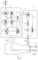
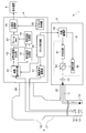
- FIG. 1 is a block diagram for explaining an example of the entire configuration of an endoscope system according to an embodiment of the present invention.
- the endoscope system 1 is configured to be inserted into a body cavity of a subject and to capture an object such as a living tissue present in the body cavity and to output an imaging signal.
- Endoscope 22 a light source device 3 configured to supply light to be irradiated to the subject to the endoscope 2, and various processes for an imaging signal output from the endoscope 2.
- It has a processor 4 configured to generate and output an observation image by applying, and a display device 5 configured to display the observation image output from the processor 4 on a screen.
- the endoscope 2 has an insertion portion 21 formed in an elongated shape that can be inserted into a body cavity of a subject, and an operation portion 22 provided on the proximal end side of the insertion portion 21. , Is configured.
- the endoscope 2 is configured to be detachable from the light source device 3 via the light guide cable 27.
- the endoscope 2 is configured to be detachable from the processor 4 via a signal cable 28 extended from the operation unit 22.
- a light guide 11 for transmitting light supplied from the light source device 3 is inserted into the insertion portion 21 and the light guide cable 27.
- the emission end of the light guide 11 is disposed near the illumination lens 12 at the tip of the insertion portion 21 as shown in FIG. Further, as shown in FIG. 1, the incident end of the light guide 11 is disposed in the vicinity of the condenser lens 32 in the light source device 3 connected to the endoscope 2 via the light guide cable 27.
- An illumination lens 12 for emitting light transmitted by the light guide 11 to the outside and an objective lens 13 for receiving light incident from the outside are provided at the tip of the insertion portion 21.
- an imaging device 14 and an excitation light cut filter 15 disposed on an optical path from the objective lens 13 to the imaging device 14 are provided.
- the imaging device 14 includes, for example, a color CMOS image sensor having a primary or complementary color filter attached to the imaging surface, and configured to perform an imaging operation according to an imaging device drive signal output from the processor 4 ing.
- the imaging device 14 is configured to capture the light transmitted through the excitation light cut filter 15 to generate an imaging signal, and to output the generated imaging signal to the processor 4.
- the excitation light cut filter 15 blocks the same wavelength band as the excitation light EXA (described later) among the wavelength bands included in the light emitted through the objective lens 13, for example, and also selects a wavelength band different from the excitation light EXA. It is formed to have an optical characteristic that allows transmission. That is, the excitation light cut filter 15 is formed to have an optical characteristic that transmits the fluorescence FLA (described later) emitted from the fluorescent agent in response to the irradiation of the excitation light EXA.
- the imaging unit of the present embodiment is configured to include the imaging element 14 and the excitation light cut filter 15.
- the operation unit 22 is provided on the proximal end side of the insertion unit 21 and has a shape that can be held by a user such as an operator. Further, the operation unit 22 is provided with, for example, a scope switch (not shown) which is one or more switches capable of performing various instructions to the processor 4 according to the user's operation.
- a scope switch (not shown) which is one or more switches capable of performing various instructions to the processor 4 according to the user's operation.
- the light source device 3 as the illumination unit includes a light emitting unit 31, a condensing lens 32, and a light source driving unit 33.
- the light emitting unit 31 includes a white light source 51, an excitation light source 52, and a dichroic mirror 53.
- the white light source 51 is configured to include, for example, either a xenon lamp, a white LED, or a red, green, and blue three-color LED.
- the white light source 51 is configured to generate white light WLA, which is light including wavelength bands of, for example, a red color region, a green color region, and a blue color region, according to the light source drive signal output from the light source drive unit 33. ing.
- a wide band light source configured to include a lamp that emits wide band light that is light having a wavelength band from at least the blue band to the near infrared band;
- the light source device 3 is provided with an optical filter having an optical characteristic that transmits the same wavelength band as the wavelength band of the white light WLA among the wavelength bands included in the wide band light and blocks the other wavelength bands. It may be done.
- the excitation light source 52 comprises, for example, an LD (laser diode). Further, the excitation light source 52 generates the excitation light EXA, which is narrow band light including the excitation wavelength of the predetermined fluorescent agent to be administered to the subject, for example, according to the light source drive signal output from the light source drive unit 33 Is configured as.
- the fluorescent agent administered to the subject is ICG (indocyanine green)
- the excitation light EXA is a narrow-band near infrared light including the excitation wavelength of ICG
- the fluorescence FLA which is near infrared light belonging to the wavelength band on the longer wavelength side than the excitation light EXA, is emitted from the ICG.
- the dichroic mirror 53 transmits, for example, the white light WLA emitted from the white light source 51 and emits it to the condensing lens 32 side, and reflects the excitation light EXA emitted from the excitation light source 52 to emit it to the condensing lens 32 side It is configured to have the following optical characteristics.
- the light emitting unit 31 is configured to be capable of generating the white light WLA by causing the white light source 51 to emit light in accordance with the drive signal output from the light source drive unit 33.
- the light emitting unit 31 is configured to be able to generate the excitation light EXA by causing the excitation light source 52 to emit light according to the drive signal output from the light source drive unit 33. Further, the light emitting unit 31 is configured to be able to emit the white light WLA and the excitation light EXA to the condensing lens 32.
- the condensing lens 32 is configured to condense the light emitted from the light emitting unit 31 and to emit the light to the incident end of the light guide 11.
- the light source drive unit 33 is configured to generate a light source drive signal for driving the white light source 51 and the excitation light source 52 based on the control signal output from the processor 4 and output the generated light source drive signal to the light emitting unit 31.
- the light source device 3 can emit excitation light EXA for exciting the fluorescent agent to be administered to the subject and white light WLA which is illumination light for illuminating the body cavity of the subject. Is configured as.
- the processor 4 includes an imaging device driving unit 41, an image reading unit 42, a white light image generating unit 43, a fluorescence image generating unit 44, a superimposed image generating unit 45, and a TV signal. It is configured to have a conversion unit 46 and a clock control unit 48. According to this embodiment, for example, each unit of the processor 4 may be configured as an individual electronic circuit, or is configured as a circuit block in an integrated circuit such as an FPGA (Field Programmable Gate Array). It is also good.
- FPGA Field Programmable Gate Array
- the imaging device drive unit 41 is configured to generate and output an imaging device drive signal for driving the imaging device 14 based on the control signal output from the clock control unit 48.
- the image reading unit 42 sets the output destination of the imaging signal output from the endoscope 2 to either the white light image generation unit 43 or the fluorescence image generation unit 44 based on the control signal output from the clock control unit 48. It is configured to perform an action to
- the white light image generation unit 43 is configured to generate the white light image WIA based on the imaging signal output through the image readout unit 42 and to output the generated white light image WIA to the superimposed image generation unit 45. It is done. That is, the white light image generation unit 43 is configured to generate a white light image WIA that is an image according to the reflected light of the white light WLA captured by the imaging device 14.
- the fluorescence image generation unit 44 is configured to generate a fluorescence image FIA based on the imaging signal output through the image readout unit 42, and to output the generated fluorescence image FIA to the superimposed image generation unit 45. . That is, the fluorescence image generation unit 44 is configured to generate a fluorescence image FIA that is an image according to the fluorescence FLA captured by the imaging device 14.
- the superimposed image generation unit 45 as an image superimposing unit is configured to be able to perform an operation according to the control signal output from the clock control unit 48. Further, the superimposed image generation unit 45 performs a process of superimposing the white light image WIA output from the white light image generation unit 43 and the fluorescence image FIA output from the fluorescence image generation unit 44. The image SIA is generated, and the generated superimposed image SIA is output to the TV signal conversion unit 46.
- the TV signal conversion unit 46 as a signal conversion unit is a video signal of a method capable of displaying the superimposed image SIA input from the superimposed image generation unit 45 based on the control signal output from the clock control unit 48 by the display device 5. Convert to
- the clock generation unit and the clock control unit 48 as the clock control unit generate the white light WLA and the excitation light EXA at the light emission unit 31, the imaging operation of the imaging device 14, and the output of the imaging signal input to the processor 4.
- a control signal for synchronizing the above is generated and output to the light source drive unit 33, the imaging device drive unit 41, and the image reading unit 42, respectively.
- the clock control unit 48 outputs a control signal for controlling the output operation of the video signal to be output to the display device 5 to the TV signal conversion unit 46.
- the timings of all the control signals are adjusted based on the generation timings of the frames or fields of the video signal to be output to the display device 5.
- the operation and the like of the endoscope system 1 of the present embodiment will be described.
- ICG fluorescent drug
- the white light image WIA obtained by imaging the subject irradiated with the white light WLA is an observation method for causing the display device 5 to display the white light image WIA as an observation image. Shall be omitted.
- the user connects each part of the endoscope system 1 and turns on the power, and then operates, for example, a fluorescence observation start switch (not shown) to clock an instruction for starting the fluorescence observation of the subject.
- the control unit 48 is performed. Further, the user inserts the insertion portion 21 into the body cavity of the subject, thereby arranging the distal end portion of the insertion portion 21 in the vicinity of the desired subject existing in the body cavity.
- the clock control unit 48 When the processor 4 is powered on, the clock control unit 48 generates a control signal for controlling the output timing of the video signal and outputs the control signal to the TV signal conversion unit 46. Further, when an instruction from the fluorescence observation start switch is detected, the generation timing of the white light WLA and the excitation light EXA in the light emitting unit 31, the imaging operation in the imaging device 14, and the output destination of the imaging signal input to the processor 4 And a control signal for synchronizing the image signal based on the timing of the control signal that controls the output timing of the video signal, and outputs the control signal to the light source drive unit 33, the imaging device drive unit 41, and the image reading unit 42.
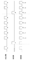
- FIG. 2 is a timing chart for explaining an example of imaging timings of the white light image and the fluorescence image according to the first embodiment.
- the imaging timing of the white light image WIA, the imaging timing of the fluorescence image FIA, and the generation timing of the superimposed image SIA to be a video signal are all generated at the same clock. There is.
- the generation timing of the superimposed image SIA is used for generating the white light image WIA, and about 10% to 20% is used for generating the fluorescence image FIA. That is, after the white light image WIA is continuously generated about five to nine times at the generation timing of the superimposed image SIA, the fluorescence image FIA is generated once.
- the superimposed image SIA is generated by repeating the cycle of generating the fluorescent light image FIA once after generating five white light images WIA successively.
- the frame rate of the fluorescence image FIA is one sixth of the frame rate of the superimposed image SIA.
- the white light image WIA has a drop for one frame every seven frames of the superimposed image SIA, six frames for continuous imaging can be acquired at the same rate as the superimposed image SIA. . Therefore, the frame rate of the white light image WIA is higher than when the white light image WIA and the fluorescence image FIA are generated alternately (in time division), so that a more natural and smooth motion image can be generated. .
- the superimposed image SIA is generated by superimposing the white light image WIA captured immediately before and the fluorescent image FIA.
- the superimposed image FIA is generated as follows. That is, in the third clock, the white light image h1 generated in the first clock and the fluorescence image f1 generated in the second clock are superimposed. In the fourth clock, the white light image h2 generated in the third clock and the fluorescence image generated in the second clock are superimposed. In the fifth clock, the white light image h3 generated in the fourth clock and the fluorescence image f1 generated in the second clock are superimposed.
- the clock control unit 48 generates, for example, a control signal for causing the imaging device 14 to perform a rolling shutter type imaging operation, and outputs the control signal to the imaging device driving unit 41. Further, the clock control unit 48, for example, excites the white light WLA of the light amount AL1 and the excitation of the light amount AL1 at each blanking period which is a period during which the reading is not performed in all the lines of the imaging device 14 A control signal for generating the light EXA at the above timing is generated and output to the light source drive unit 33. That is, each time the white light WLA is continuously generated a preset number of times (for example, 5 times), the control signal is generated and output to the light source drive unit 33 so as to generate the excitation light EXA once.
- a preset number of times for example, 5 times
- the clock control unit 48 sets the output destination of the imaging signal input to the processor 4 at the time of generation of the white light WLA in the white light image generation unit 43 and is input to the processor 4 at the time of generation of the excitation light EXA.
- the control signal for setting the output destination of the imaging signal to the fluorescence image generation unit 44 is generated and output to the image reading unit 42.
- white light is generated in the first blanking period, the third to seventh blanking periods, and the eighth and ninth blanking periods of the imaging device 14.
- a subject is irradiated with WLA, reflected light of white light WLA which is return light generated from the subject is imaged by the imaging device 14, and an imaging signal generated by the imaging device 14 passes through the image reading unit 42 to generate white light image
- the white light image WIA output to the unit 43 and generated based on the imaging signal is output to each of the superimposed image generation unit 45 and the TV signal conversion unit 46.
- the excitation light EXA is irradiated to the subject at one timing for each of six blanking periods, and the fluorescence FLA included in the return light generated from the subject is imaged by the imaging element 14, and the imaging element 14
- the imaging signal generated by the above is output to the fluorescence image generation unit 44 via the image readout unit 42, and the fluorescence image FIA generated based on the imaging signal is output to the superimposed image generation unit 45.
- the superimposed image generation unit 45 performs processing for superimposing the white light image WIA output from the white light image generation unit 43 and the fluorescence image FIA output from the fluorescence image generation unit 44, thereby generating a superimposed image SIA.
- the generated superimposed image SIA is output to the TV signal conversion unit 46. That is, according to the operation of such a superimposed image generation unit 45, a superimposed image SIA in which the occurrence position of the fluorescence FLA in the subject imaged by the endoscope 2 is shown in green is output to the mixed TV signal conversion unit 46 Be done.
- the TV signal conversion unit 46 outputs the superimposed image SIA output from the superimposed image generation unit 45 to the display device 5 as an observation image based on the control signal output from the clock control unit 48.
- the fluorescence image FIA is acquired once every predetermined number of frames (for example, six frames), and the white light image WIA is fluorescence. Acquisition is performed in consecutive frames (for example, 5 consecutive frames) while acquiring the image FIA. Therefore, while continuously updating the information indicating the structure such as unevenness of the living tissue included in the white light image WIA as continuously as possible, the observation image to which the information indicating the generation location of the fluorescence FLA included in the superimposed image SIA is added is displayed It can be displayed on 5. Therefore, according to the present embodiment, when observing the fluorescence emitted from the living tissue, it is possible to realize an image of smooth and natural movement.
- the configuration of the endoscope system 1 may be modified as appropriate to be compatible with other fluorescent agents other than ICG.
- narrow-band blue light including the excitation wavelength of fluorescein is emitted from the excitation light source 52 as excitation light EXB
- white light WLA is A half mirror that reflects the excitation light EXB while transmitting is provided instead of the dichroic mirror 53
- light of the same wavelength band as the excitation light EXB is blocked by the excitation light cut filter 15, and irradiation of the excitation light EXB is performed. Accordingly, light in the visible range including fluorescence FLB which is green light emitted from fluorescein may be transmitted through the excitation light cut filter 15.
- the timing for acquiring the fluorescence image FIA is not fixed at a preset timing (for example, one frame every six consecutive frames), and for example, the user can freely set from the outside, or the fluorescence image FIA It may be adjusted dynamically according to the brightness of the image.
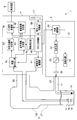
- FIG. 3 is a block diagram for explaining another example of the entire configuration of the endoscope system according to the embodiment of the present invention.
- an input I / F 47 enables the user to set the acquisition timing of the fluorescence image from the user, and the luminance of the fluorescence image FIA generated by the fluorescence image generation unit 44 And a fluorescence rate control unit 50 for setting the timing for acquiring the fluorescence image FIA.
- the set timing is output to the fluorescence rate control unit 50.
- the fluorescence rate control unit 50 acquires the fluorescence image FIA at the input timing, and outputs a control signal to the clock control unit 48 so that the white light image WIA is continuously acquired for the frames in between.
- the luminance of the fluorescence image FIA generated by the fluorescence image generation unit 44 is measured by the luminance measurement unit 49, and the measurement result is the fluorescence rate Output to the control unit 50.
- the fluorescence rate control unit 50 outputs a control signal to the clock control unit 48 so as to increase the acquisition rate of the fluorescence image FIA.
- the clock control unit 48 outputs control signals to the imaging device driving unit 41, the image reading unit 42, the light source driving unit 33, and the TV signal reading unit 48 according to the input timing.
- the generation clock of the imaging signal for acquiring the white light image WIA and the fluorescence image FIA is acquired with the same clock as the output clock of the video signal to be displayed on the display device 5.
- the acquisition rate of the white light image WIA and the fluorescence image FIA (the clock of the imaging device 14) is faster than the timing of generating the video signal to be displayed on the display device 5 using a clock. The point to generate is different.
- the configuration of the endoscope system 1 of the present embodiment is the same as that of the endoscope system of the first embodiment described with reference to FIG. Omit.
- an operation part different from the endoscope system 1 of the first embodiment will be described.
- FIG. 4 is a timing chart for explaining an example of imaging timings of a white light image and a fluorescence image according to the second embodiment.
- the imaging timing of the white light image WIA and the imaging timing of the fluorescence image FIA are the same clock, but the generation timing of the superimposed image SIA to be a video signal is a different clock. It is generated.
- the imaging timing is generated with a clock that is faster than the generation timing of the superimposed image SIA.
- the generation clock of the imaging signal uses the generation clock of the superimposed image SIA, that is, the clock about 1.3 times the output clock of the video signal.
- three are allocated to imaging of the white light image WIA, and imaging of the fluorescence image FIA is performed at the remaining one time. That is, while three frames of the superimposed image SIA are generated, three white light images WIA can be acquired. Therefore, since there is no reduction in the frame rate of the white light image WIA, it is possible to generate an image of natural and smooth motion.
- the superimposed image SIA is generated by superimposing the white light image WIA captured immediately before and the fluorescence image FIA, as in the case of the first embodiment described with reference to FIG.
- the generated clock of the imaging signal is set to n times (n is a decimal or an integer larger than 1) of the output clock of the video signal to generate the white light image WIA. Assigns clocks such that the number of clocks per unit time is the same as the number of clocks of the video signal, and assigns the remaining clocks to the fluorescence image FIA. Therefore, since the frame rate of the white light image WIA can be made the same rate as the frame rate of the video signal while acquiring the fluorescence image FIA, the continuity of the white light image WIA can be secured, and from living tissue When observing the emitted fluorescence, an image of smooth and natural motion can be realized.
- the rate of the generated clock of the imaging signal by the input I / F 47 that is, how many times as large as the output clock of the video signal May be set manually by the user.
- the same rate may be automatically changed according to the brightness in the fluorescence image FIA.
- the fluorescence rate control unit 50 outputs a control signal to the clock control unit 48 so as to increase the rate of the generation clock of the imaging signal.
- the imaging element 14 when acquiring the white light image WIA and the fluorescence image FIA, the imaging element 14 reads out and outputs an imaging signal pixel by pixel.
- both the white light image WIA and the fluorescence image FIA are different in that plural pieces of pixel information are collectively output by binning.
- the configuration of the endoscope system 1 of the present embodiment is the same as that of the endoscope system of the first embodiment described with reference to FIG. Omit.
- an operation part different from the endoscope system 1 of the first embodiment will be described.
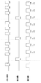
- FIG. 5 is a timing chart for explaining an example of imaging timings of a white light image and a fluorescence image according to the third embodiment.
- FIG. 5 shows a case where pixel information for two pixels is collectively output from the imaging device 14. By outputting information for two pixels together, the output time of an imaging signal for one frame is halved. That is, the frame rate can be doubled as compared to the case of reading one pixel at a time.
- the frame rate of the superimposed image SIA and the frame rate of the white light image WIA can be equalized, so natural and smooth It can generate motion pictures.
- the number of pixels collectively output by binning is not limited to two.
- it is also possible to further raise the frame rates of the white light image WIA and the fluorescence image FIA by outputting more pixels, such as 2 ⁇ 2 4 pixels, collectively.
- the clock control unit 48 controls the generation timing of the white light WLA and the excitation light EXA in the light emitting unit 31, the imaging operation in the imaging device 14, and the imaging input to the processor 4.
- the control signal for synchronizing the output destination of the signal is generated based on the timing of the control signal that controls the output timing of the video signal, and is output to the light source drive unit 33, the imaging device drive unit 41, and the image reading unit 42, respectively.
- the present embodiment differs in that the control signal for controlling the output timing of the video signal and the control signal for controlling the generation timing of the white light image WIA and the fluorescence image FIA are generated independently. There is.
- FIG. 6 is a block diagram for explaining an example of the entire configuration of the endoscope system according to the fourth embodiment of the present invention.
- the configuration of the endoscope system 1 shown in FIG. 6 is the same as that of the first embodiment described with reference to FIG. 1 except that a frame memory 61 and a TV clock control unit 62 are provided in the processor 4.
- the same components as those of the endoscope system are denoted by the same reference numerals and the description thereof is omitted.
- the frame memory 61 stores the superimposed image SIA output from the superimposed image generation unit 45.
- the TV clock control unit 62 generates the output timing of the video signal according to the input specification of the video signal that can be displayed on the display device 5 and outputs the timing to the TV signal conversion unit 46 as a control signal.
- the TV signal conversion unit 46 acquires the superimposed image SIA from the frame memory 61 at a predetermined timing in accordance with the control signal input from the TV clock control unit 62, and outputs the superimposed image SIA to the display device 5.
- the generation timing of the white light image WIA and the fluorescence image FIA can be obtained by using any of the methods shown in the first, second and third embodiments. When observing the fluorescence emitted from the living tissue, it is possible to realize an image of smooth and natural movement.
- the output timing of the video signal is not performed by the TV clock control unit 62, but may be asynchronously performed by the clock control unit 48 independently of the generation timing of the white light image WIA and the fluorescence image FIA. Good.
- each “unit” in the present specification is a conceptual one corresponding to each function of the embodiment, and does not necessarily correspond one to one to a specific hardware or software routine. Therefore, in the present specification, the embodiments have been described assuming virtual circuit blocks (sections) having the respective functions of the embodiments.
- the order of execution may be changed, a plurality of steps may be performed simultaneously, or different steps may be performed for each execution.
- all or part of each step of each procedure in the present embodiment may be realized by hardware.
Landscapes
- Health & Medical Sciences (AREA)
- Life Sciences & Earth Sciences (AREA)
- Surgery (AREA)
- Physics & Mathematics (AREA)
- Engineering & Computer Science (AREA)
- Optics & Photonics (AREA)
- Biophysics (AREA)
- Animal Behavior & Ethology (AREA)
- Pathology (AREA)
- Radiology & Medical Imaging (AREA)
- Veterinary Medicine (AREA)
- Biomedical Technology (AREA)
- Heart & Thoracic Surgery (AREA)
- Medical Informatics (AREA)
- Molecular Biology (AREA)
- Nuclear Medicine, Radiotherapy & Molecular Imaging (AREA)
- General Health & Medical Sciences (AREA)
- Public Health (AREA)
- Signal Processing (AREA)
- Astronomy & Astrophysics (AREA)
- General Physics & Mathematics (AREA)
- Multimedia (AREA)
- Endoscopes (AREA)
Abstract
Système d'endoscope (1) comprenant : un dispositif de source de lumière (3) pour émettre de la lumière blanche et de la lumière d'excitation d'une manière multiplexée par répartition dans le temps et en synchronisation avec une horloge générée à une temporisation prédéfinie ; un élément d'imagerie (14) pour capturer une image d'une image de lumière blanche et d'une image fluorescente et délivrer en sortie un signal d'imagerie pour chaque image ; une unité de génération d'image superposée (45) pour superposer le signal de lumière blanche et le signal fluorescent délivré en sortie par l'élément d'imagerie (14) pour générer un signal superposé ; et une unité de conversion de signal TV (46) pour convertir le signal superposé en un signal d'affichage de moniteur. Le système d'endoscope (1) comprend également une unité de commande d'horloge (48) qui commande l'unité de conversion de signal TV (46) au moyen de l'horloge générée à un premier instant nécessaire pour une trame/champ nécessaire pour la conversion dans le signal d'affichage de moniteur, et qui ajuste les instants de capture d'image de l'image de lumière blanche et de l'image fluorescente par l'élément d'imagerie (14) à l'encontre de la première synchronisation.
Priority Applications (2)
| Application Number | Priority Date | Filing Date | Title |
|---|---|---|---|
| JP2019560825A JP6956805B2 (ja) | 2017-12-22 | 2018-10-15 | 内視鏡システム、内視鏡システムの制御方法 |
| US16/907,499 US11805977B2 (en) | 2017-12-22 | 2020-06-22 | Endoscope system and control method for endoscope system |
Applications Claiming Priority (2)
| Application Number | Priority Date | Filing Date | Title |
|---|---|---|---|
| JP2017-247012 | 2017-12-22 | ||
| JP2017247012 | 2017-12-22 |
Related Child Applications (1)
| Application Number | Title | Priority Date | Filing Date |
|---|---|---|---|
| US16/907,499 Continuation US11805977B2 (en) | 2017-12-22 | 2020-06-22 | Endoscope system and control method for endoscope system |
Publications (1)
| Publication Number | Publication Date |
|---|---|
| WO2019123796A1 true WO2019123796A1 (fr) | 2019-06-27 |
Family
ID=66992768
Family Applications (1)
| Application Number | Title | Priority Date | Filing Date |
|---|---|---|---|
| PCT/JP2018/038315 Ceased WO2019123796A1 (fr) | 2017-12-22 | 2018-10-15 | Système d'endoscope |
Country Status (3)
| Country | Link |
|---|---|
| US (1) | US11805977B2 (fr) |
| JP (1) | JP6956805B2 (fr) |
| WO (1) | WO2019123796A1 (fr) |
Families Citing this family (26)
| Publication number | Priority date | Publication date | Assignee | Title |
|---|---|---|---|---|
| JP7048628B2 (ja) | 2016-11-28 | 2022-04-05 | アダプティブエンドウ エルエルシー | 分離可能使い捨てシャフト付き内視鏡 |
| US20190191975A1 (en) | 2017-12-27 | 2019-06-27 | Ethicon Llc | Fluorescence imaging in a light deficient environment |
| US11674848B2 (en) | 2019-06-20 | 2023-06-13 | Cilag Gmbh International | Wide dynamic range using a monochrome image sensor for hyperspectral imaging |
| US11937784B2 (en) | 2019-06-20 | 2024-03-26 | Cilag Gmbh International | Fluorescence imaging in a light deficient environment |
| US11925328B2 (en) | 2019-06-20 | 2024-03-12 | Cilag Gmbh International | Noise aware edge enhancement in a pulsed hyperspectral imaging system |
| US11624830B2 (en) | 2019-06-20 | 2023-04-11 | Cilag Gmbh International | Wide dynamic range using a monochrome image sensor for laser mapping imaging |
| US11237270B2 (en) | 2019-06-20 | 2022-02-01 | Cilag Gmbh International | Hyperspectral, fluorescence, and laser mapping imaging with fixed pattern noise cancellation |
| US11389066B2 (en) | 2019-06-20 | 2022-07-19 | Cilag Gmbh International | Noise aware edge enhancement in a pulsed hyperspectral, fluorescence, and laser mapping imaging system |
| US11758256B2 (en) * | 2019-06-20 | 2023-09-12 | Cilag Gmbh International | Fluorescence imaging in a light deficient environment |
| US11266304B2 (en) * | 2019-06-20 | 2022-03-08 | Cilag Gmbh International | Minimizing image sensor input/output in a pulsed hyperspectral imaging system |
| US12013496B2 (en) | 2019-06-20 | 2024-06-18 | Cilag Gmbh International | Noise aware edge enhancement in a pulsed laser mapping imaging system |
| US11012599B2 (en) | 2019-06-20 | 2021-05-18 | Ethicon Llc | Hyperspectral imaging in a light deficient environment |
| US11280737B2 (en) | 2019-06-20 | 2022-03-22 | Cilag Gmbh International | Super resolution and color motion artifact correction in a pulsed fluorescence imaging system |
| US11311183B2 (en) | 2019-06-20 | 2022-04-26 | Cilag Gmbh International | Controlling integral energy of a laser pulse in a fluorescence imaging system |
| US11686847B2 (en) | 2019-06-20 | 2023-06-27 | Cilag Gmbh International | Pulsed illumination in a fluorescence imaging system |
| US11700995B2 (en) * | 2019-06-20 | 2023-07-18 | Cilag Gmbh International | Speckle removal in a pulsed fluorescence imaging system |
| US11471055B2 (en) * | 2019-06-20 | 2022-10-18 | Cilag Gmbh International | Noise aware edge enhancement in a pulsed fluorescence imaging system |
| US11898909B2 (en) | 2019-06-20 | 2024-02-13 | Cilag Gmbh International | Noise aware edge enhancement in a pulsed fluorescence imaging system |
| US11622094B2 (en) * | 2019-06-20 | 2023-04-04 | Cilag Gmbh International | Wide dynamic range using a monochrome image sensor for fluorescence imaging |
| US12126887B2 (en) | 2019-06-20 | 2024-10-22 | Cilag Gmbh International | Hyperspectral and fluorescence imaging with topology laser scanning in a light deficient environment |
| US11716543B2 (en) | 2019-06-20 | 2023-08-01 | Cilag Gmbh International | Wide dynamic range using a monochrome image sensor for fluorescence imaging |
| USD1018844S1 (en) | 2020-01-09 | 2024-03-19 | Adaptivendo Llc | Endoscope handle |
| USD1051380S1 (en) | 2020-11-17 | 2024-11-12 | Adaptivendo Llc | Endoscope handle |
| USD1031035S1 (en) | 2021-04-29 | 2024-06-11 | Adaptivendo Llc | Endoscope handle |
| USD1070082S1 (en) | 2021-04-29 | 2025-04-08 | Adaptivendo Llc | Endoscope handle |
| USD1066659S1 (en) | 2021-09-24 | 2025-03-11 | Adaptivendo Llc | Endoscope handle |
Citations (3)
| Publication number | Priority date | Publication date | Assignee | Title |
|---|---|---|---|---|
| JP2001078175A (ja) * | 1999-07-07 | 2001-03-23 | Fuji Photo Film Co Ltd | 蛍光観察装置 |
| JP2001327458A (ja) * | 2000-05-25 | 2001-11-27 | Fuji Photo Film Co Ltd | 蛍光撮像装置 |
| JP6205531B1 (ja) * | 2016-09-06 | 2017-09-27 | オリンパス株式会社 | 内視鏡システム |
Family Cites Families (6)
| Publication number | Priority date | Publication date | Assignee | Title |
|---|---|---|---|---|
| JPS57204604A (en) | 1981-06-11 | 1982-12-15 | Mitsubishi Electric Corp | Shared branching filter for orthogonal double polarized wave |
| NZ513117A (en) * | 1999-01-26 | 2004-04-30 | Newton Lab Inc | Autofluorescence imaging system for endoscopy |
| US6468204B2 (en) | 2000-05-25 | 2002-10-22 | Fuji Photo Film Co., Ltd. | Fluorescent endoscope apparatus |
| JP2008161550A (ja) * | 2006-12-28 | 2008-07-17 | Olympus Corp | 内視鏡システム |
| JP5628062B2 (ja) * | 2011-02-01 | 2014-11-19 | 富士フイルム株式会社 | 電子内視鏡システム |
| WO2018047369A1 (fr) | 2016-09-06 | 2018-03-15 | オリンパス株式会社 | Système d'endoscope |
-
2018
- 2018-10-15 WO PCT/JP2018/038315 patent/WO2019123796A1/fr not_active Ceased
- 2018-10-15 JP JP2019560825A patent/JP6956805B2/ja active Active
-
2020
- 2020-06-22 US US16/907,499 patent/US11805977B2/en active Active
Patent Citations (3)
| Publication number | Priority date | Publication date | Assignee | Title |
|---|---|---|---|---|
| JP2001078175A (ja) * | 1999-07-07 | 2001-03-23 | Fuji Photo Film Co Ltd | 蛍光観察装置 |
| JP2001327458A (ja) * | 2000-05-25 | 2001-11-27 | Fuji Photo Film Co Ltd | 蛍光撮像装置 |
| JP6205531B1 (ja) * | 2016-09-06 | 2017-09-27 | オリンパス株式会社 | 内視鏡システム |
Also Published As
| Publication number | Publication date |
|---|---|
| US11805977B2 (en) | 2023-11-07 |
| JPWO2019123796A1 (ja) | 2020-11-19 |
| US20200315439A1 (en) | 2020-10-08 |
| JP6956805B2 (ja) | 2021-11-02 |
Similar Documents
| Publication | Publication Date | Title |
|---|---|---|
| JP6956805B2 (ja) | 内視鏡システム、内視鏡システムの制御方法 | |
| CN103491847B (zh) | 内窥镜装置和荧光观察的光量控制方法 | |
| JP5259882B2 (ja) | 撮像装置 | |
| US20200337540A1 (en) | Endoscope system | |
| JP5427316B2 (ja) | 撮像装置 | |
| US10901199B2 (en) | Endoscope system having variable focal length lens that switches between two or more values | |
| JP7219208B2 (ja) | 内視鏡装置 | |
| JP6228833B2 (ja) | 撮像システム、及び内視鏡装置 | |
| JP2018182580A (ja) | 撮像装置及び撮像装置の制御プログラム | |
| JP2018175871A (ja) | 撮像装置及び撮像装置の制御プログラム | |
| JP6937902B2 (ja) | 内視鏡システム | |
| US20200252601A1 (en) | Imaging system and synchronization control method | |
| JP2014183908A (ja) | 撮像システム | |
| JP4744279B2 (ja) | 電子内視鏡装置 | |
| US11582427B2 (en) | Medical image processing apparatus and medical observation system | |
| JP7224963B2 (ja) | 医療用制御装置及び医療用観察システム | |
| JP7213245B2 (ja) | 内視鏡用光源装置、内視鏡用光源の制御方法および内視鏡システム | |
| JP6257475B2 (ja) | 走査型内視鏡装置 | |
| WO2018211600A1 (fr) | Dispositif d'imagerie, système d'endoscope, procédé de commande, et programme | |
| JP2020146407A (ja) | 光源装置、医療用観察システム、照明方法およびプログラム | |
| US20220277432A1 (en) | Medical image processing device and medical observation system | |
| WO2024211781A1 (fr) | Systèmes et procédés d'obtention d'une imagerie médicale par fluorescence avec une source d'éclairage à excitation par fluorescence modulée | |
| JP2002315722A (ja) | 電子内視鏡装置 |
Legal Events
| Date | Code | Title | Description |
|---|---|---|---|
| 121 | Ep: the epo has been informed by wipo that ep was designated in this application |
Ref document number: 18891874 Country of ref document: EP Kind code of ref document: A1 |
|
| ENP | Entry into the national phase |
Ref document number: 2019560825 Country of ref document: JP Kind code of ref document: A |
|
| NENP | Non-entry into the national phase |
Ref country code: DE |
|
| 122 | Ep: pct application non-entry in european phase |
Ref document number: 18891874 Country of ref document: EP Kind code of ref document: A1 |