WO2019123796A1 - 内視鏡システム - Google Patents
内視鏡システム Download PDFInfo
- Publication number
- WO2019123796A1 WO2019123796A1 PCT/JP2018/038315 JP2018038315W WO2019123796A1 WO 2019123796 A1 WO2019123796 A1 WO 2019123796A1 JP 2018038315 W JP2018038315 W JP 2018038315W WO 2019123796 A1 WO2019123796 A1 WO 2019123796A1
- Authority
- WO
- WIPO (PCT)
- Prior art keywords
- image
- timing
- unit
- imaging
- signal
- Prior art date
- Legal status (The legal status is an assumption and is not a legal conclusion. Google has not performed a legal analysis and makes no representation as to the accuracy of the status listed.)
- Ceased
Links
Images

Classifications
-
- A—HUMAN NECESSITIES
- A61—MEDICAL OR VETERINARY SCIENCE; HYGIENE
- A61B—DIAGNOSIS; SURGERY; IDENTIFICATION
- A61B1/00—Instruments for performing medical examinations of the interior of cavities or tubes of the body by visual or photographical inspection, e.g. endoscopes; Illuminating arrangements therefor
- A61B1/00002—Operational features of endoscopes
- A61B1/00004—Operational features of endoscopes characterised by electronic signal processing
- A61B1/00009—Operational features of endoscopes characterised by electronic signal processing of image signals during a use of endoscope
-
- A—HUMAN NECESSITIES
- A61—MEDICAL OR VETERINARY SCIENCE; HYGIENE
- A61B—DIAGNOSIS; SURGERY; IDENTIFICATION
- A61B1/00—Instruments for performing medical examinations of the interior of cavities or tubes of the body by visual or photographical inspection, e.g. endoscopes; Illuminating arrangements therefor
- A61B1/00002—Operational features of endoscopes
- A61B1/00004—Operational features of endoscopes characterised by electronic signal processing
- A61B1/00006—Operational features of endoscopes characterised by electronic signal processing of control signals
-
- A—HUMAN NECESSITIES
- A61—MEDICAL OR VETERINARY SCIENCE; HYGIENE
- A61B—DIAGNOSIS; SURGERY; IDENTIFICATION
- A61B1/00—Instruments for performing medical examinations of the interior of cavities or tubes of the body by visual or photographical inspection, e.g. endoscopes; Illuminating arrangements therefor
- A61B1/00002—Operational features of endoscopes
- A61B1/00043—Operational features of endoscopes provided with output arrangements
- A61B1/00045—Display arrangement
-
- A—HUMAN NECESSITIES
- A61—MEDICAL OR VETERINARY SCIENCE; HYGIENE
- A61B—DIAGNOSIS; SURGERY; IDENTIFICATION
- A61B1/00—Instruments for performing medical examinations of the interior of cavities or tubes of the body by visual or photographical inspection, e.g. endoscopes; Illuminating arrangements therefor
- A61B1/04—Instruments for performing medical examinations of the interior of cavities or tubes of the body by visual or photographical inspection, e.g. endoscopes; Illuminating arrangements therefor combined with photographic or television appliances
- A61B1/043—Instruments for performing medical examinations of the interior of cavities or tubes of the body by visual or photographical inspection, e.g. endoscopes; Illuminating arrangements therefor combined with photographic or television appliances for fluorescence imaging
-
- A—HUMAN NECESSITIES
- A61—MEDICAL OR VETERINARY SCIENCE; HYGIENE
- A61B—DIAGNOSIS; SURGERY; IDENTIFICATION
- A61B1/00—Instruments for performing medical examinations of the interior of cavities or tubes of the body by visual or photographical inspection, e.g. endoscopes; Illuminating arrangements therefor
- A61B1/04—Instruments for performing medical examinations of the interior of cavities or tubes of the body by visual or photographical inspection, e.g. endoscopes; Illuminating arrangements therefor combined with photographic or television appliances
- A61B1/045—Control thereof
-
- A—HUMAN NECESSITIES
- A61—MEDICAL OR VETERINARY SCIENCE; HYGIENE
- A61B—DIAGNOSIS; SURGERY; IDENTIFICATION
- A61B1/00—Instruments for performing medical examinations of the interior of cavities or tubes of the body by visual or photographical inspection, e.g. endoscopes; Illuminating arrangements therefor
- A61B1/04—Instruments for performing medical examinations of the interior of cavities or tubes of the body by visual or photographical inspection, e.g. endoscopes; Illuminating arrangements therefor combined with photographic or television appliances
- A61B1/05—Instruments for performing medical examinations of the interior of cavities or tubes of the body by visual or photographical inspection, e.g. endoscopes; Illuminating arrangements therefor combined with photographic or television appliances characterised by the image sensor, e.g. camera, being in the distal end portion
-
- A—HUMAN NECESSITIES
- A61—MEDICAL OR VETERINARY SCIENCE; HYGIENE
- A61B—DIAGNOSIS; SURGERY; IDENTIFICATION
- A61B1/00—Instruments for performing medical examinations of the interior of cavities or tubes of the body by visual or photographical inspection, e.g. endoscopes; Illuminating arrangements therefor
- A61B1/06—Instruments for performing medical examinations of the interior of cavities or tubes of the body by visual or photographical inspection, e.g. endoscopes; Illuminating arrangements therefor with illuminating arrangements
- A61B1/0661—Endoscope light sources
-
- G—PHYSICS
- G02—OPTICS
- G02B—OPTICAL ELEMENTS, SYSTEMS OR APPARATUS
- G02B23/00—Telescopes, e.g. binoculars; Periscopes; Instruments for viewing the inside of hollow bodies; Viewfinders; Optical aiming or sighting devices
- G02B23/24—Instruments or systems for viewing the inside of hollow bodies, e.g. fibrescopes
- G02B23/26—Instruments or systems for viewing the inside of hollow bodies, e.g. fibrescopes using light guides
-
- H—ELECTRICITY
- H04—ELECTRIC COMMUNICATION TECHNIQUE
- H04N—PICTORIAL COMMUNICATION, e.g. TELEVISION
- H04N7/00—Television systems
- H04N7/18—Closed-circuit television [CCTV] systems, i.e. systems in which the video signal is not broadcast
Definitions
- Embodiments of the present invention relate to an endoscope system, and more particularly to an endoscope system used for fluorescence observation.
- the frame rate of the white light image is reduced to one half of the normal. For this reason, the continuity of the white light image is lost, and when the superimposed image is displayed as a moving image, there is a problem that the smoothness is lost and the motion becomes unnatural motion.
- an object of the present invention to provide an endoscope system capable of realizing a smooth and natural motion image when displaying an image by superimposing a white light image and a fluorescence image in fluorescence observation. To aim.
- the endoscope system includes a clock generation unit configured to be able to generate a clock at a predetermined timing, and capable of irradiating white light and excitation light in time division in synchronization with the clock. And an imaging unit that performs imaging based on the irradiation timing of the illumination unit with respect to the subject and outputs a white light signal and a fluorescence signal as imaging signals.
- an image superimposing unit that generates the superimposed signal by superimposing the white light signal output from the imaging unit and the fluorescence signal, and converts the superimposed signal output from the image overlapping unit into a monitor display signal
- the signal conversion unit is controlled by a signal conversion unit, a frame necessary for conversion to the monitor display signal, or a clock generated at a first timing necessary for a field, and the first timing is used as a reference. It also includes a clock control unit configured to be capable of adjusting the imaging timing of each of the white light image and the fluorescence image in the imaging unit.
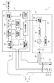
- FIG. 2 is a block diagram for explaining another example of the entire configuration of the endoscope system according to the embodiment of the present invention.
- the timing chart explaining an example of the imaging timing of the white light image concerning a 2nd embodiment, and a fluorescence picture.
- the timing chart explaining an example of the imaging timing of the white_light
- the block diagram explaining an example of the whole structure of the endoscope system concerning the 4th Embodiment of this invention.
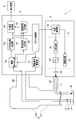
- FIG. 1 is a block diagram for explaining an example of the entire configuration of an endoscope system according to an embodiment of the present invention.
- the endoscope system 1 is configured to be inserted into a body cavity of a subject and to capture an object such as a living tissue present in the body cavity and to output an imaging signal.
- Endoscope 22 a light source device 3 configured to supply light to be irradiated to the subject to the endoscope 2, and various processes for an imaging signal output from the endoscope 2.
- It has a processor 4 configured to generate and output an observation image by applying, and a display device 5 configured to display the observation image output from the processor 4 on a screen.
- the endoscope 2 has an insertion portion 21 formed in an elongated shape that can be inserted into a body cavity of a subject, and an operation portion 22 provided on the proximal end side of the insertion portion 21. , Is configured.
- the endoscope 2 is configured to be detachable from the light source device 3 via the light guide cable 27.
- the endoscope 2 is configured to be detachable from the processor 4 via a signal cable 28 extended from the operation unit 22.
- a light guide 11 for transmitting light supplied from the light source device 3 is inserted into the insertion portion 21 and the light guide cable 27.
- the emission end of the light guide 11 is disposed near the illumination lens 12 at the tip of the insertion portion 21 as shown in FIG. Further, as shown in FIG. 1, the incident end of the light guide 11 is disposed in the vicinity of the condenser lens 32 in the light source device 3 connected to the endoscope 2 via the light guide cable 27.
- An illumination lens 12 for emitting light transmitted by the light guide 11 to the outside and an objective lens 13 for receiving light incident from the outside are provided at the tip of the insertion portion 21.
- an imaging device 14 and an excitation light cut filter 15 disposed on an optical path from the objective lens 13 to the imaging device 14 are provided.
- the imaging device 14 includes, for example, a color CMOS image sensor having a primary or complementary color filter attached to the imaging surface, and configured to perform an imaging operation according to an imaging device drive signal output from the processor 4 ing.
- the imaging device 14 is configured to capture the light transmitted through the excitation light cut filter 15 to generate an imaging signal, and to output the generated imaging signal to the processor 4.
- the excitation light cut filter 15 blocks the same wavelength band as the excitation light EXA (described later) among the wavelength bands included in the light emitted through the objective lens 13, for example, and also selects a wavelength band different from the excitation light EXA. It is formed to have an optical characteristic that allows transmission. That is, the excitation light cut filter 15 is formed to have an optical characteristic that transmits the fluorescence FLA (described later) emitted from the fluorescent agent in response to the irradiation of the excitation light EXA.
- the imaging unit of the present embodiment is configured to include the imaging element 14 and the excitation light cut filter 15.
- the operation unit 22 is provided on the proximal end side of the insertion unit 21 and has a shape that can be held by a user such as an operator. Further, the operation unit 22 is provided with, for example, a scope switch (not shown) which is one or more switches capable of performing various instructions to the processor 4 according to the user's operation.
- a scope switch (not shown) which is one or more switches capable of performing various instructions to the processor 4 according to the user's operation.
- the light source device 3 as the illumination unit includes a light emitting unit 31, a condensing lens 32, and a light source driving unit 33.
- the light emitting unit 31 includes a white light source 51, an excitation light source 52, and a dichroic mirror 53.
- the white light source 51 is configured to include, for example, either a xenon lamp, a white LED, or a red, green, and blue three-color LED.
- the white light source 51 is configured to generate white light WLA, which is light including wavelength bands of, for example, a red color region, a green color region, and a blue color region, according to the light source drive signal output from the light source drive unit 33. ing.
- a wide band light source configured to include a lamp that emits wide band light that is light having a wavelength band from at least the blue band to the near infrared band;
- the light source device 3 is provided with an optical filter having an optical characteristic that transmits the same wavelength band as the wavelength band of the white light WLA among the wavelength bands included in the wide band light and blocks the other wavelength bands. It may be done.
- the excitation light source 52 comprises, for example, an LD (laser diode). Further, the excitation light source 52 generates the excitation light EXA, which is narrow band light including the excitation wavelength of the predetermined fluorescent agent to be administered to the subject, for example, according to the light source drive signal output from the light source drive unit 33 Is configured as.
- the fluorescent agent administered to the subject is ICG (indocyanine green)
- the excitation light EXA is a narrow-band near infrared light including the excitation wavelength of ICG
- the fluorescence FLA which is near infrared light belonging to the wavelength band on the longer wavelength side than the excitation light EXA, is emitted from the ICG.
- the dichroic mirror 53 transmits, for example, the white light WLA emitted from the white light source 51 and emits it to the condensing lens 32 side, and reflects the excitation light EXA emitted from the excitation light source 52 to emit it to the condensing lens 32 side It is configured to have the following optical characteristics.
- the light emitting unit 31 is configured to be capable of generating the white light WLA by causing the white light source 51 to emit light in accordance with the drive signal output from the light source drive unit 33.
- the light emitting unit 31 is configured to be able to generate the excitation light EXA by causing the excitation light source 52 to emit light according to the drive signal output from the light source drive unit 33. Further, the light emitting unit 31 is configured to be able to emit the white light WLA and the excitation light EXA to the condensing lens 32.
- the condensing lens 32 is configured to condense the light emitted from the light emitting unit 31 and to emit the light to the incident end of the light guide 11.
- the light source drive unit 33 is configured to generate a light source drive signal for driving the white light source 51 and the excitation light source 52 based on the control signal output from the processor 4 and output the generated light source drive signal to the light emitting unit 31.
- the light source device 3 can emit excitation light EXA for exciting the fluorescent agent to be administered to the subject and white light WLA which is illumination light for illuminating the body cavity of the subject. Is configured as.
- the processor 4 includes an imaging device driving unit 41, an image reading unit 42, a white light image generating unit 43, a fluorescence image generating unit 44, a superimposed image generating unit 45, and a TV signal. It is configured to have a conversion unit 46 and a clock control unit 48. According to this embodiment, for example, each unit of the processor 4 may be configured as an individual electronic circuit, or is configured as a circuit block in an integrated circuit such as an FPGA (Field Programmable Gate Array). It is also good.
- FPGA Field Programmable Gate Array
- the imaging device drive unit 41 is configured to generate and output an imaging device drive signal for driving the imaging device 14 based on the control signal output from the clock control unit 48.
- the image reading unit 42 sets the output destination of the imaging signal output from the endoscope 2 to either the white light image generation unit 43 or the fluorescence image generation unit 44 based on the control signal output from the clock control unit 48. It is configured to perform an action to
- the white light image generation unit 43 is configured to generate the white light image WIA based on the imaging signal output through the image readout unit 42 and to output the generated white light image WIA to the superimposed image generation unit 45. It is done. That is, the white light image generation unit 43 is configured to generate a white light image WIA that is an image according to the reflected light of the white light WLA captured by the imaging device 14.
- the fluorescence image generation unit 44 is configured to generate a fluorescence image FIA based on the imaging signal output through the image readout unit 42, and to output the generated fluorescence image FIA to the superimposed image generation unit 45. . That is, the fluorescence image generation unit 44 is configured to generate a fluorescence image FIA that is an image according to the fluorescence FLA captured by the imaging device 14.
- the superimposed image generation unit 45 as an image superimposing unit is configured to be able to perform an operation according to the control signal output from the clock control unit 48. Further, the superimposed image generation unit 45 performs a process of superimposing the white light image WIA output from the white light image generation unit 43 and the fluorescence image FIA output from the fluorescence image generation unit 44. The image SIA is generated, and the generated superimposed image SIA is output to the TV signal conversion unit 46.
- the TV signal conversion unit 46 as a signal conversion unit is a video signal of a method capable of displaying the superimposed image SIA input from the superimposed image generation unit 45 based on the control signal output from the clock control unit 48 by the display device 5. Convert to
- the clock generation unit and the clock control unit 48 as the clock control unit generate the white light WLA and the excitation light EXA at the light emission unit 31, the imaging operation of the imaging device 14, and the output of the imaging signal input to the processor 4.
- a control signal for synchronizing the above is generated and output to the light source drive unit 33, the imaging device drive unit 41, and the image reading unit 42, respectively.
- the clock control unit 48 outputs a control signal for controlling the output operation of the video signal to be output to the display device 5 to the TV signal conversion unit 46.
- the timings of all the control signals are adjusted based on the generation timings of the frames or fields of the video signal to be output to the display device 5.
- the operation and the like of the endoscope system 1 of the present embodiment will be described.
- ICG fluorescent drug
- the white light image WIA obtained by imaging the subject irradiated with the white light WLA is an observation method for causing the display device 5 to display the white light image WIA as an observation image. Shall be omitted.
- the user connects each part of the endoscope system 1 and turns on the power, and then operates, for example, a fluorescence observation start switch (not shown) to clock an instruction for starting the fluorescence observation of the subject.
- the control unit 48 is performed. Further, the user inserts the insertion portion 21 into the body cavity of the subject, thereby arranging the distal end portion of the insertion portion 21 in the vicinity of the desired subject existing in the body cavity.
- the clock control unit 48 When the processor 4 is powered on, the clock control unit 48 generates a control signal for controlling the output timing of the video signal and outputs the control signal to the TV signal conversion unit 46. Further, when an instruction from the fluorescence observation start switch is detected, the generation timing of the white light WLA and the excitation light EXA in the light emitting unit 31, the imaging operation in the imaging device 14, and the output destination of the imaging signal input to the processor 4 And a control signal for synchronizing the image signal based on the timing of the control signal that controls the output timing of the video signal, and outputs the control signal to the light source drive unit 33, the imaging device drive unit 41, and the image reading unit 42.
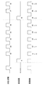
- FIG. 2 is a timing chart for explaining an example of imaging timings of the white light image and the fluorescence image according to the first embodiment.
- the imaging timing of the white light image WIA, the imaging timing of the fluorescence image FIA, and the generation timing of the superimposed image SIA to be a video signal are all generated at the same clock. There is.
- the generation timing of the superimposed image SIA is used for generating the white light image WIA, and about 10% to 20% is used for generating the fluorescence image FIA. That is, after the white light image WIA is continuously generated about five to nine times at the generation timing of the superimposed image SIA, the fluorescence image FIA is generated once.
- the superimposed image SIA is generated by repeating the cycle of generating the fluorescent light image FIA once after generating five white light images WIA successively.
- the frame rate of the fluorescence image FIA is one sixth of the frame rate of the superimposed image SIA.
- the white light image WIA has a drop for one frame every seven frames of the superimposed image SIA, six frames for continuous imaging can be acquired at the same rate as the superimposed image SIA. . Therefore, the frame rate of the white light image WIA is higher than when the white light image WIA and the fluorescence image FIA are generated alternately (in time division), so that a more natural and smooth motion image can be generated. .
- the superimposed image SIA is generated by superimposing the white light image WIA captured immediately before and the fluorescent image FIA.
- the superimposed image FIA is generated as follows. That is, in the third clock, the white light image h1 generated in the first clock and the fluorescence image f1 generated in the second clock are superimposed. In the fourth clock, the white light image h2 generated in the third clock and the fluorescence image generated in the second clock are superimposed. In the fifth clock, the white light image h3 generated in the fourth clock and the fluorescence image f1 generated in the second clock are superimposed.
- the clock control unit 48 generates, for example, a control signal for causing the imaging device 14 to perform a rolling shutter type imaging operation, and outputs the control signal to the imaging device driving unit 41. Further, the clock control unit 48, for example, excites the white light WLA of the light amount AL1 and the excitation of the light amount AL1 at each blanking period which is a period during which the reading is not performed in all the lines of the imaging device 14 A control signal for generating the light EXA at the above timing is generated and output to the light source drive unit 33. That is, each time the white light WLA is continuously generated a preset number of times (for example, 5 times), the control signal is generated and output to the light source drive unit 33 so as to generate the excitation light EXA once.
- a preset number of times for example, 5 times
- the clock control unit 48 sets the output destination of the imaging signal input to the processor 4 at the time of generation of the white light WLA in the white light image generation unit 43 and is input to the processor 4 at the time of generation of the excitation light EXA.
- the control signal for setting the output destination of the imaging signal to the fluorescence image generation unit 44 is generated and output to the image reading unit 42.
- white light is generated in the first blanking period, the third to seventh blanking periods, and the eighth and ninth blanking periods of the imaging device 14.
- a subject is irradiated with WLA, reflected light of white light WLA which is return light generated from the subject is imaged by the imaging device 14, and an imaging signal generated by the imaging device 14 passes through the image reading unit 42 to generate white light image
- the white light image WIA output to the unit 43 and generated based on the imaging signal is output to each of the superimposed image generation unit 45 and the TV signal conversion unit 46.
- the excitation light EXA is irradiated to the subject at one timing for each of six blanking periods, and the fluorescence FLA included in the return light generated from the subject is imaged by the imaging element 14, and the imaging element 14
- the imaging signal generated by the above is output to the fluorescence image generation unit 44 via the image readout unit 42, and the fluorescence image FIA generated based on the imaging signal is output to the superimposed image generation unit 45.
- the superimposed image generation unit 45 performs processing for superimposing the white light image WIA output from the white light image generation unit 43 and the fluorescence image FIA output from the fluorescence image generation unit 44, thereby generating a superimposed image SIA.
- the generated superimposed image SIA is output to the TV signal conversion unit 46. That is, according to the operation of such a superimposed image generation unit 45, a superimposed image SIA in which the occurrence position of the fluorescence FLA in the subject imaged by the endoscope 2 is shown in green is output to the mixed TV signal conversion unit 46 Be done.
- the TV signal conversion unit 46 outputs the superimposed image SIA output from the superimposed image generation unit 45 to the display device 5 as an observation image based on the control signal output from the clock control unit 48.
- the fluorescence image FIA is acquired once every predetermined number of frames (for example, six frames), and the white light image WIA is fluorescence. Acquisition is performed in consecutive frames (for example, 5 consecutive frames) while acquiring the image FIA. Therefore, while continuously updating the information indicating the structure such as unevenness of the living tissue included in the white light image WIA as continuously as possible, the observation image to which the information indicating the generation location of the fluorescence FLA included in the superimposed image SIA is added is displayed It can be displayed on 5. Therefore, according to the present embodiment, when observing the fluorescence emitted from the living tissue, it is possible to realize an image of smooth and natural movement.
- the configuration of the endoscope system 1 may be modified as appropriate to be compatible with other fluorescent agents other than ICG.
- narrow-band blue light including the excitation wavelength of fluorescein is emitted from the excitation light source 52 as excitation light EXB
- white light WLA is A half mirror that reflects the excitation light EXB while transmitting is provided instead of the dichroic mirror 53
- light of the same wavelength band as the excitation light EXB is blocked by the excitation light cut filter 15, and irradiation of the excitation light EXB is performed. Accordingly, light in the visible range including fluorescence FLB which is green light emitted from fluorescein may be transmitted through the excitation light cut filter 15.
- the timing for acquiring the fluorescence image FIA is not fixed at a preset timing (for example, one frame every six consecutive frames), and for example, the user can freely set from the outside, or the fluorescence image FIA It may be adjusted dynamically according to the brightness of the image.
- FIG. 3 is a block diagram for explaining another example of the entire configuration of the endoscope system according to the embodiment of the present invention.
- an input I / F 47 enables the user to set the acquisition timing of the fluorescence image from the user, and the luminance of the fluorescence image FIA generated by the fluorescence image generation unit 44 And a fluorescence rate control unit 50 for setting the timing for acquiring the fluorescence image FIA.
- the set timing is output to the fluorescence rate control unit 50.
- the fluorescence rate control unit 50 acquires the fluorescence image FIA at the input timing, and outputs a control signal to the clock control unit 48 so that the white light image WIA is continuously acquired for the frames in between.
- the luminance of the fluorescence image FIA generated by the fluorescence image generation unit 44 is measured by the luminance measurement unit 49, and the measurement result is the fluorescence rate Output to the control unit 50.
- the fluorescence rate control unit 50 outputs a control signal to the clock control unit 48 so as to increase the acquisition rate of the fluorescence image FIA.
- the clock control unit 48 outputs control signals to the imaging device driving unit 41, the image reading unit 42, the light source driving unit 33, and the TV signal reading unit 48 according to the input timing.
- the generation clock of the imaging signal for acquiring the white light image WIA and the fluorescence image FIA is acquired with the same clock as the output clock of the video signal to be displayed on the display device 5.
- the acquisition rate of the white light image WIA and the fluorescence image FIA (the clock of the imaging device 14) is faster than the timing of generating the video signal to be displayed on the display device 5 using a clock. The point to generate is different.
- the configuration of the endoscope system 1 of the present embodiment is the same as that of the endoscope system of the first embodiment described with reference to FIG. Omit.
- an operation part different from the endoscope system 1 of the first embodiment will be described.
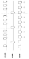
- FIG. 4 is a timing chart for explaining an example of imaging timings of a white light image and a fluorescence image according to the second embodiment.
- the imaging timing of the white light image WIA and the imaging timing of the fluorescence image FIA are the same clock, but the generation timing of the superimposed image SIA to be a video signal is a different clock. It is generated.
- the imaging timing is generated with a clock that is faster than the generation timing of the superimposed image SIA.
- the generation clock of the imaging signal uses the generation clock of the superimposed image SIA, that is, the clock about 1.3 times the output clock of the video signal.
- three are allocated to imaging of the white light image WIA, and imaging of the fluorescence image FIA is performed at the remaining one time. That is, while three frames of the superimposed image SIA are generated, three white light images WIA can be acquired. Therefore, since there is no reduction in the frame rate of the white light image WIA, it is possible to generate an image of natural and smooth motion.
- the superimposed image SIA is generated by superimposing the white light image WIA captured immediately before and the fluorescence image FIA, as in the case of the first embodiment described with reference to FIG.
- the generated clock of the imaging signal is set to n times (n is a decimal or an integer larger than 1) of the output clock of the video signal to generate the white light image WIA. Assigns clocks such that the number of clocks per unit time is the same as the number of clocks of the video signal, and assigns the remaining clocks to the fluorescence image FIA. Therefore, since the frame rate of the white light image WIA can be made the same rate as the frame rate of the video signal while acquiring the fluorescence image FIA, the continuity of the white light image WIA can be secured, and from living tissue When observing the emitted fluorescence, an image of smooth and natural motion can be realized.
- the rate of the generated clock of the imaging signal by the input I / F 47 that is, how many times as large as the output clock of the video signal May be set manually by the user.
- the same rate may be automatically changed according to the brightness in the fluorescence image FIA.
- the fluorescence rate control unit 50 outputs a control signal to the clock control unit 48 so as to increase the rate of the generation clock of the imaging signal.
- the imaging element 14 when acquiring the white light image WIA and the fluorescence image FIA, the imaging element 14 reads out and outputs an imaging signal pixel by pixel.
- both the white light image WIA and the fluorescence image FIA are different in that plural pieces of pixel information are collectively output by binning.
- the configuration of the endoscope system 1 of the present embodiment is the same as that of the endoscope system of the first embodiment described with reference to FIG. Omit.
- an operation part different from the endoscope system 1 of the first embodiment will be described.
- FIG. 5 is a timing chart for explaining an example of imaging timings of a white light image and a fluorescence image according to the third embodiment.
- FIG. 5 shows a case where pixel information for two pixels is collectively output from the imaging device 14. By outputting information for two pixels together, the output time of an imaging signal for one frame is halved. That is, the frame rate can be doubled as compared to the case of reading one pixel at a time.
- the frame rate of the superimposed image SIA and the frame rate of the white light image WIA can be equalized, so natural and smooth It can generate motion pictures.
- the number of pixels collectively output by binning is not limited to two.
- it is also possible to further raise the frame rates of the white light image WIA and the fluorescence image FIA by outputting more pixels, such as 2 ⁇ 2 4 pixels, collectively.
- the clock control unit 48 controls the generation timing of the white light WLA and the excitation light EXA in the light emitting unit 31, the imaging operation in the imaging device 14, and the imaging input to the processor 4.
- the control signal for synchronizing the output destination of the signal is generated based on the timing of the control signal that controls the output timing of the video signal, and is output to the light source drive unit 33, the imaging device drive unit 41, and the image reading unit 42, respectively.
- the present embodiment differs in that the control signal for controlling the output timing of the video signal and the control signal for controlling the generation timing of the white light image WIA and the fluorescence image FIA are generated independently. There is.
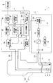
- FIG. 6 is a block diagram for explaining an example of the entire configuration of the endoscope system according to the fourth embodiment of the present invention.
- the configuration of the endoscope system 1 shown in FIG. 6 is the same as that of the first embodiment described with reference to FIG. 1 except that a frame memory 61 and a TV clock control unit 62 are provided in the processor 4.
- the same components as those of the endoscope system are denoted by the same reference numerals and the description thereof is omitted.
- the frame memory 61 stores the superimposed image SIA output from the superimposed image generation unit 45.
- the TV clock control unit 62 generates the output timing of the video signal according to the input specification of the video signal that can be displayed on the display device 5 and outputs the timing to the TV signal conversion unit 46 as a control signal.
- the TV signal conversion unit 46 acquires the superimposed image SIA from the frame memory 61 at a predetermined timing in accordance with the control signal input from the TV clock control unit 62, and outputs the superimposed image SIA to the display device 5.
- the generation timing of the white light image WIA and the fluorescence image FIA can be obtained by using any of the methods shown in the first, second and third embodiments. When observing the fluorescence emitted from the living tissue, it is possible to realize an image of smooth and natural movement.
- the output timing of the video signal is not performed by the TV clock control unit 62, but may be asynchronously performed by the clock control unit 48 independently of the generation timing of the white light image WIA and the fluorescence image FIA. Good.
- each “unit” in the present specification is a conceptual one corresponding to each function of the embodiment, and does not necessarily correspond one to one to a specific hardware or software routine. Therefore, in the present specification, the embodiments have been described assuming virtual circuit blocks (sections) having the respective functions of the embodiments.
- the order of execution may be changed, a plurality of steps may be performed simultaneously, or different steps may be performed for each execution.
- all or part of each step of each procedure in the present embodiment may be realized by hardware.
Landscapes
- Health & Medical Sciences (AREA)
- Life Sciences & Earth Sciences (AREA)
- Surgery (AREA)
- Physics & Mathematics (AREA)
- Engineering & Computer Science (AREA)
- Optics & Photonics (AREA)
- Biophysics (AREA)
- Animal Behavior & Ethology (AREA)
- Pathology (AREA)
- Radiology & Medical Imaging (AREA)
- Veterinary Medicine (AREA)
- Biomedical Technology (AREA)
- Heart & Thoracic Surgery (AREA)
- Medical Informatics (AREA)
- Molecular Biology (AREA)
- Nuclear Medicine, Radiotherapy & Molecular Imaging (AREA)
- General Health & Medical Sciences (AREA)
- Public Health (AREA)
- Signal Processing (AREA)
- Astronomy & Astrophysics (AREA)
- General Physics & Mathematics (AREA)
- Multimedia (AREA)
- Endoscopes (AREA)
Abstract
内視鏡システム(1)は、所定のタイミングで生成されるクロックに同期して白色光と励起光とを時分割で照射する光源装置(3)と、白色光像と蛍光像とを撮像して各々撮像信号を出力する撮像素子(14)と、撮像素子(14)から出力された白色光信号と蛍光信号とを重畳し、重畳信号を生成する重畳画像生成部(45)と、重畳信号をモニタ表示信号に変換するTV信号変換部(46)とを備える。また、モニタ表示信号に変換するために必要なフレーム/フィールドに必要な第1タイミングで生成されたクロックでTV信号変換部(46)を制御すると共に、第1タイミングを基準として撮像素子(14)における白色光像と蛍光像の各々の撮像タイミングを調整するクロック制御部(48)を備える。
Description
本発明の実施形態は、内視鏡システムに関し、特に、蛍光観察に用いられる内視鏡システムに関する。
従来、医療分野において、ICGなどの蛍光薬剤を被検体に投与した後に、励起光を照射し、投与した薬剤から発せられる薬剤蛍光を撮像することで、血管やリンパ管の特定や血流の確認を行う蛍光観察が広く行われている。
薬剤蛍光によって得られる信号は微弱であるため、蛍光画像は不鮮明な画像になってしまう。そこで、鮮明な画像を得るために、蛍光画像と白色光画像とを時分割で取得して、重畳した合成画像を表示させる内視鏡システムが提案されている(例えば、日本国特開2012-157559号公報参照)。
しかしながら、上述の提案においては、白色光画像のフレームレートが通常の二分の一になってしまう。このため、白色光画像の連続性が失われてしまい、重畳画像を動画表示すると、滑らかさが損なわれカクカクとした不自然な動きとなってしまう、という問題があった。
そこで、本発明は、蛍光観察において、白色光画像と蛍光画像とを重畳して映像表示する場合に、滑らかで自然な動きの映像を実現することができる、内視鏡システムを提供することを目的とする。
本発明の一態様の内視鏡システムは、所定のタイミングでクロックを生成可能に構成されるクロック生成部と、前記クロックに同期して白色光と励起光とを時分割で照射可能に構成される照明部と、被検体に対する前記照明部からの照射タイミングに基づき撮像を行い、撮像信号として、白色光信号及び蛍光信号を各々出力する撮像部を有する。また、前記撮像部から出力された前記白色光信号及び前記蛍光信号を重畳して、重畳信号として生成する画像重畳部と、前記画像重畳部から出力された前記重畳信号を、モニタ表示信号に変換する信号変換部と、前記モニタ表示信号に変換するために必要なフレーム、又は、フィールドに必要な第1タイミングで生成されたクロックで前記信号変換部を制御すると共に、前記第1タイミングを基準として前記撮像部における前記白色光像、及び、前記蛍光像の各々の撮像タイミングを調整可能に構成されるクロック制御部とも備える。
以下、図面を参照して実施形態を説明する。
(第1の実施形態)
図1は、本発明の実施形態に係わる内視鏡システムの全体構成の一例を説明するブロック図である。
図1は、本発明の実施形態に係わる内視鏡システムの全体構成の一例を説明するブロック図である。
内視鏡システム1は、例えば、図1に示すように、被検体の体腔内に挿入されるとともに、当該体腔内に存在する生体組織等の被写体を撮像して撮像信号を出力するように構成された内視鏡2と、当該被写体に照射される光を内視鏡2に供給するように構成された光源装置3と、内視鏡2から出力される撮像信号に対して種々の処理を施すことにより観察画像を生成して出力するように構成されたプロセッサ4と、プロセッサ4から出力される観察画像を画面上に表示するように構成された表示装置5と、を有している。
内視鏡2は、例えば、図1に示すように、被検体の体腔内に挿入可能な細長形状に形成された挿入部21と、挿入部21の基端側に設けられた操作部22と、を有して構成されている。また、内視鏡2は、ライトガイドケーブル27を介し、光源装置3に対して着脱可能な構成を具備している。また、内視鏡2は、操作部22から延設された信号ケーブル28を介し、プロセッサ4に対して着脱可能な構成を具備している。
挿入部21及びライトガイドケーブル27の内部には、光源装置3から供給される光を伝送するためのライトガイド11が挿通されている。
ライトガイド11の出射端部は、図1に示すように、挿入部21の先端部における照明レンズ12の近傍に配置されている。また、ライトガイド11の入射端部は、図1に示すように、ライトガイドケーブル27を介して内視鏡2に接続されている光源装置3における集光レンズ32の近傍に配置されている。
挿入部21の先端部には、ライトガイド11により伝送された光を外部へ出射するための照明レンズ12と、外部から入射される光を受光するための対物レンズ13と、が設けられている。また、挿入部21の先端部には、撮像素子14と、対物レンズ13から撮像素子14に至るまでの光路上に配置された励起光カットフィルタ15と、が設けられている。
撮像素子14は、例えば、原色系または補色系のカラーフィルタを撮像面に取り付けたカラーCMOSイメージセンサを具備し、プロセッサ4から出力される撮像素子駆動信号に応じた撮像動作を行うように構成されている。また、撮像素子14は、励起光カットフィルタ15を透過した光を撮像して撮像信号を生成するとともに、当該生成した撮像信号をプロセッサ4へ出力するように構成されている。
励起光カットフィルタ15は、例えば、対物レンズ13を経て出射される光に含まれる各波長帯域のうち、励起光EXA(後述)と同じ波長帯域を遮断するとともに、励起光EXAと異なる波長帯域を透過させるような光学特性を具備して形成されている。すなわち、励起光カットフィルタ15は、励起光EXAの照射に応じて蛍光薬剤から発せられる蛍光FLA(後述)を透過させるような光学特性を具備して形成されている。
すなわち、本実施形態の撮像部は、撮像素子14と、励起光カットフィルタ15と、を有して構成されている。
操作部22は、挿入部21の基端側に設けられているとともに、術者等のユーザが把持可能な形状を具備して形成されている。また、操作部22には、例えば、ユーザの操作に応じた種々の指示をプロセッサ4に対して行うことが可能な1つ以上のスイッチであるスコープスイッチ(不図示)が設けられている。
照明部としての光源装置3は、例えば、図1に示すように、発光部31と、集光レンズ32と、光源駆動部33と、を有して構成されている。
発光部31は、白色光源51と、励起光源52と、ダイクロイックミラー53と、を有して構成されている。
白色光源51は、例えば、キセノンランプ、白色LED、または、赤色、緑色及び青色の3色のLEDのいずれかを具備して構成されている。また、白色光源51は、光源駆動部33から出力される光源駆動信号に応じ、例えば、赤色域、緑色域及び青色域の各波長帯域を含む光である白色光WLAを発生するように構成されている。なお、本実施形態においては、白色光源51の代わりに、例えば、少なくとも青色域から近赤外域までの波長帯域を具備する光である広帯域光を発するランプを具備して構成された広帯域光源と、当該広帯域光に含まれる各波長帯域のうちの白色光WLAの波長帯域と同じ波長帯域を透過させつつ他の波長帯域を遮断するような光学特性を具備する光学フィルタと、が光源装置3に設けられていてもよい。
励起光源52は、例えば、LD(レーザダイオード)を具備して構成されている。また、励起光源52は、光源駆動部33から出力される光源駆動信号に応じ、例えば、被検体に投与される所定の蛍光薬剤の励起波長を含む狭帯域な光である励起光EXAを発生するように構成されている。なお、以降においては、特に言及の無い限り、被検体に投与される蛍光薬剤がICG(インドシアニングリーン)であり、励起光EXAがICGの励起波長を含む狭帯域な近赤外光であり、かつ、励起光EXAよりも長波長側の波長帯域に属する近赤外光である蛍光FLAがICGから発せられるものとして説明を行う。
ダイクロイックミラー53は、例えば、白色光源51から発せられる白色光WLAを透過させて集光レンズ32側へ出射するとともに、励起光源52から発せられる励起光EXAを反射して集光レンズ32側へ出射するような光学特性を具備して構成されている。
すなわち、発光部31は、光源駆動部33から出力される駆動信号に応じて白色光源51を発光させることにより、白色光WLAを発生することができるように構成されている。また、発光部31は、光源駆動部33から出力される駆動信号に応じて励起光源52を発光させることにより、励起光EXAを発生することができるように構成されている。また、発光部31は、白色光WLA及び励起光EXAを集光レンズ32へ出射することができるように構成されている。
集光レンズ32は、発光部31から出射される光を集光してライトガイド11の入射端部へ出射するように構成されている。
光源駆動部33は、プロセッサ4から出力される制御信号に基づき、白色光源51及び励起光源52を駆動させるための光源駆動信号を生成して発光部31へ出力するように構成されている。
すなわち、光源装置3は、被検体に投与される蛍光薬剤を励起させるための励起光EXAと、当該被検体の体腔内を照明するための照明光である白色光WLAと、を発することができるように構成されている。
プロセッサ4は、例えば、図1に示すように、撮像素子駆動部41と、画像読み出し部42と、白色光画像生成部43と、蛍光画像生成部44と、重畳画像生成部45と、TV信号変換部46と、クロック制御部48と、を有して構成されている。なお、本実施形態によれば、例えば、プロセッサ4の各部が、個々の電子回路として構成されていてもよく、または、FPGA(Field Programmable Gate Array)等の集積回路における回路ブロックとして構成されていてもよい。
撮像素子駆動部41は、クロック制御部48から出力される制御信号に基づき、撮像素子14を駆動させるための撮像素子駆動信号を生成して出力するように構成されている。
画像読み出し部42は、クロック制御部48から出力される制御信号に基づき、内視鏡2から出力される撮像信号の出力先を白色光画像生成部43または蛍光画像生成部44のいずれかに設定するための動作を行うように構成されている。
白色光画像生成部43は、画像読み出し部42を経て出力される撮像信号に基づいて白色光画像WIAを生成するとともに、当該生成した白色光画像WIAを重畳画像生成部45へ出力するように構成されている。すなわち、白色光画像生成部43は、撮像素子14により撮像された白色光WLAの反射光に応じた画像である白色光画像WIAを生成するように構成されている。
蛍光画像生成部44は、画像読み出し部42を経て出力される撮像信号に基づいて蛍光画像FIAを生成するとともに、当該生成した蛍光画像FIAを重畳画像生成部45へ出力するように構成されている。すなわち、蛍光画像生成部44は、撮像素子14により撮像された蛍光FLAに応じた画像である蛍光画像FIAを生成するように構成されている。
画像重畳部としての重畳画像生成部45は、クロック制御部48から出力される制御信号に応じた動作を行うことができるように構成されている。また、重畳画像生成部45は、白色光画像生成部43から出力される白色光画像WIAと、蛍光画像生成部44から出力される蛍光画像FIAと、を重畳するための処理を行うことにより重畳画像SIAを生成し、当該生成した重畳画像SIAをTV信号変換部46へ出力するように構成されている。
信号変換部としてのTV信号変換部46は、クロック制御部48から出力される制御信号に基づき、重畳画像生成部45から入力される重畳画像SIAを、表示装置5で表示可能な方式の映像信号に変換する。
クロック生成部、及びクロック制御部としてのクロック制御部48は、発光部31における白色光WLA及び励起光EXAの発生タイミングと、撮像素子14における撮像動作と、プロセッサ4に入力される撮像信号の出力先と、を同期させるための制御信号を生成して光源駆動部33、撮像素子駆動部41及び画像読み出し部42へそれぞれ出力するように構成されている。また、クロック制御部48は、表示装置5に出力する映像信号の出力動作を制御するための制御信号を、TV信号変換部46に出力する。なお、全ての制御信号のタイミングは、表示装置5に出力する映像信号のフレームまたはフィールドの生成タイミングに基づき、調整される。
次に、本実施形態の内視鏡システム1の動作等について説明する。なお、以降においては、被検体の体腔内に存在する所望の被写体の蛍光観察が行われる前に、当該所望の被写体にICG(蛍光薬剤)が予め投与されているものとして説明を進める。また、以降においては、簡単のため、白色光WLAが照射された被写体を撮像して得られる白色光画像WIAを観察画像として表示装置5に表示させるような観察手法である、白色光観察に関する説明を省略するものとする。
まず、ユーザは、内視鏡システム1の各部を接続して電源を投入した後、例えば、蛍光観察開始スイッチ(不図示)を操作することにより、被写体の蛍光観察を開始させるための指示をクロック制御部48に対して行う。また、ユーザは、挿入部21を被検体の体腔内に挿入してゆくことにより、当該体腔内に存在する所望の被写体の近傍に挿入部21の先端部を配置する。
クロック制御部48は、プロセッサ4の電源が投入されると、映像信号の出力タイミングを制御する制御信号を生成して、TV信号変換部46へ出力する。また、蛍光観察開始スイッチからの指示を検知した際に、発光部31における白色光WLA及び励起光EXAの発生タイミングと、撮像素子14における撮像動作と、プロセッサ4に入力される撮像信号の出力先と、を同期させるための制御信号を、映像信号の出力タイミングを制御する制御信号のタイミングに基づき生成して光源駆動部33、撮像素子駆動部41及び画像読み出し部42へそれぞれ出力する。
図2は、第1の実施形態に係わる白色光画像と蛍光画像の撮像タイミングの一例を説明するタイミングチャートである。図2に示すように、本実施形態においては、白色光画像WIAの撮像タイミングと、蛍光画像FIAの撮像タイミングと、映像信号となる重畳画像SIAの生成タイミングとは、全て同じクロックで生成されている。
ここで、重畳画像SIAの生成タイミングのうち、8~9割程度を白色光画像WIAの生成に用い、1割~2割程度を蛍光画像FIAの生成に用いる。すなわち、重畳画像SIAの生成タイミングで、5回~9回程度、白色光画像WIAを連続して生成した後、蛍光画像FIAを1回生成する。例えば、図2に示すように、白色光画像WIAを5画像連続して生成した後に蛍光画像FIAを1回生成する周期を繰り返して、重畳画像SIAを生成する場合を考える。この場合、蛍光画像FIAのフレームレートは、重畳画像SIAのフレームレートの六分の一になる。しかしながら、白色光画像WIAは、重畳画像SIAが7フレーム生成される毎に1フレーム分の欠落があるものの、連続して撮像する6フレーム分は、重畳画像SIAと同じレートで取得することができる。よって、白色光画像WIAと蛍光画像FIAとを交互に(時分割に)生成する場合に比べ、白色光画像WIAのフレームレートが上がるので、より自然で滑らかな動きの映像を生成することができる。
なお、重畳画像SIAは、直前に撮像された白色光画像WIAと蛍光画像FIAとを重畳して生成される。例えば、1番目のクロックで白色光画像h1、2番目のクロックで蛍光画像f1、3番目~7番目のクロックで白色光画像h2~h6、8番目のクロックで蛍光画像f2、9番目、10番目のクロックで白色光画像h7、78を生成する場合、重畳画像FIAは、次のように生成される。すなわち、3番目のクロックでは、1番目のクロックで生成された白色光画像h1と、2番目のクロックで生成された蛍光画像f1とを重畳する。4番目のクロックでは3番目のクロックで生成された白色光画像h2と、2番目のクロックで生成された蛍光画像とを重畳する。5番目のクロックでは、4番目のクロックで生成された白色光画像h3と、2番目のクロックで生成された蛍光画像f1とを重畳する。
具体的には、クロック制御部48は、例えば、ローリングシャッタ方式の撮像動作を撮像素子14に行わせるための制御信号を生成して撮像素子駆動部41へ出力する。また、クロック制御部48は、例えば、ローリングシャッタ方式の撮像動作において撮像素子14の全ラインで読み出しが行われない期間であるブランキング期間毎に、光量AL1の白色光WLA及び当該光量AL1の励起光EXAを上記のタイミングで発生させるための制御信号を生成して光源駆動部33へ出力する。すなわち、白色光WLAを予め設定された回数(例えば、5回)連続して発生させる都度、励起光EXAを1回発生させるように、制御信号を生成して光源駆動部33へ出力する。
また、クロック制御部48は、例えば、白色光WLAの発生時にプロセッサ4に入力される撮像信号の出力先を白色光画像生成部43に設定するとともに、励起光EXAの発生時にプロセッサ4に入力される撮像信号の出力先を蛍光画像生成部44に設定するための制御信号を生成して画像読み出し部42へ出力する。
そして、前述のようなクロック制御部48の制御によれば、例えば、撮像素子14の1番目のブランキング期間、3番目~7番目のブランキング期間、8、9番目のブランキング期間において白色光WLAが被写体に照射され、当該被写体から発生する戻り光である白色光WLAの反射光が撮像素子14により撮像され、撮像素子14により生成された撮像信号が画像読み出し部42を経て白色光画像生成部43へ出力され、当該撮像信号に基づいて生成された白色光画像WIAが重畳画像生成部45及びTV信号変換部46の各々へ出力される。
また、前述のようなクロック制御部48の制御によれば、例えば、前述の1番目、3~7番目、…ブランキング期間とは異なる撮像素子14のブランキング期間、すなわち、2番目、8番目、…と、6回のブランキング期間に対して1回のタイミングにおいて励起光EXAが被写体に照射され、当該被写体から発生する戻り光に含まれる蛍光FLAが撮像素子14により撮像され、撮像素子14により生成された撮像信号が画像読み出し部42を経て蛍光画像生成部44へ出力され、当該撮像信号に基づいて生成された蛍光画像FIAが重畳画像生成部45へ出力される。
重畳画像生成部45は、白色光画像生成部43から出力される白色光画像WIAと、蛍光画像生成部44から出力される蛍光画像FIAと、を重畳するための処理を行うことにより重畳画像SIAを生成し、当該生成した重畳画像SIAをTV信号変換部46へ出力する。すなわち、このような重畳画像生成部45の動作によれば、内視鏡2により撮像された被写体における蛍光FLAの発生箇所が緑色で示されるような重畳画像SIAが混合TV信号変換部46へ出力される。
TV信号変換部46は、クロック制御部48から出力される制御信号に基づき、重畳画像生成部45から出力される重畳画像SIAを、観察画像として表示装置5へ出力する。
以上に述べたように、本実施形態の内視鏡システム1によれば、蛍光画像FIAはあらかじめ設定されたフレーム数(例えば、6フレーム)ごとに1回取得し、白色光画像WIAは、蛍光画像FIAを取得する間の連続したフレーム(例えば、連続した5フレーム)で取得する。従って、白色光画像WIAに含まれる生体組織の凹凸等の構造を示す情報を極力連続的に更新しつつ、重畳画像SIAに含まれる蛍光FLAの発生箇所を示す情報を付与した観察画像を表示装置5に表示させることができる。そのため、本実施形態によれば、生体組織から発せられる蛍光を観察する際に、滑らかで自然な動きの映像を実現することができる。
なお、本実施形態によれば、内視鏡システム1の構成を適宜変形することにより、ICG以外の他の蛍光薬剤に対応させるようにしてもよい。
具体的には、例えば、被検体に投与される蛍光薬剤がフルオレセインである場合には、フルオレセインの励起波長を含む狭帯域な青色光が励起光EXBとして励起光源52から発せられ、白色光WLAを透過させつつ励起光EXBを反射するようなハーフミラーがダイクロイックミラー53の代わりに設けられ、励起光EXBと同じ波長帯域の光が励起光カットフィルタ15において遮断され、かつ、励起光EXBの照射に応じてフルオレセインから発せられる緑色光である蛍光FLBを含む可視域の光が励起光カットフィルタ15を透過するようにすればよい。
また、蛍光画像FIAを取得するタイミングは、予め設定されたタイミング(例えば、連続する6フレーム毎に1フレーム)に固定されず、例えば、ユーザが外部から自由に設定できるようにしたり、蛍光画像FIAの輝度に応じて動的に調整したりするようにしてもよい。
図3は、本発明の実施形態に係わる内視鏡システムの全体構成の別の一例を説明するブロック図である。例えば図3に示すように、図1に構成に加え、プロセッサ4に、ユーザから蛍光画像の取得タイミングを設定可能とする入力I/F47、蛍光画像生成部44で生成された蛍光画像FIAの輝度を測定する輝度測定部49、蛍光画像FIAを取得するタイミングを設定する蛍光レート制御部50を更に設ける。
入力I/F47において、ユーザが蛍光取得のタイミングを設定する場合、設定されたタイミングは蛍光レート制御部50に出力される。蛍光レート制御部50は入力されたタイミングで蛍光画像FIAを取得し、その間のフレームは連続して白色光画像WIAを取得するように、クロック制御部48に対して制御信号を出力する。
また、蛍光画像FIAの輝度に応じて蛍光取得のタイミングを動的に変更する場合、蛍光画像生成部44で生成された蛍光画像FIAの輝度を輝度測定部49で測定し、測定結果を蛍光レート制御部50へ出力する。蛍光レート制御部50には、入力された輝度が、予め設定された基準輝度よりも低い場合、蛍光画像FIAの取得レートを上げるよう、クロック制御部48に制御信号を出力する。
クロック制御部48は入力されたタイミングに従って、撮像素子駆動部41、画像読み出し部42、光源駆動部33、TV信号読み出し部48に対して、制御信号を出力する。
このように、蛍光画像FIAの取得レートを動的に変更することで、滑らかで自然な動きを確保しつつ、蛍光FLAの発生箇所がより観察しやすい映像を実現することができる。
(第2の実施形態)
上述した第1の実施形態においては、白色光画像WIAと蛍光画像FIAを取得するための撮像信号の生成クロックは、表示装置5に表示する映像信号の出力クロックと同じクロックで取得していた。これに対し、本実施形態においては、白色光画像WIAと蛍光画像FIAの取得レート(撮像素子14のクロック)を、表示装置5に表示する映像信号を生成するタイミングより速いタイミングのクロックを用いて生成する点が異なっている。
上述した第1の実施形態においては、白色光画像WIAと蛍光画像FIAを取得するための撮像信号の生成クロックは、表示装置5に表示する映像信号の出力クロックと同じクロックで取得していた。これに対し、本実施形態においては、白色光画像WIAと蛍光画像FIAの取得レート(撮像素子14のクロック)を、表示装置5に表示する映像信号を生成するタイミングより速いタイミングのクロックを用いて生成する点が異なっている。
本実施形態の内視鏡システム1の構成は、図1を用いて説明した、第1の実施形態の内視鏡システムと同様であるため、同一の構成要素については同じ符号を付して説明を省略する。以下、第1の実施形態の内視鏡システム1と異なる、動作部分について説明する。
図4は、第2の実施形態に係わる白色光画像と蛍光画像の撮像タイミングの一例を説明するタイミングチャートである。図4に示すように、本実施形態においては、白色光画像WIAの撮像タイミングと蛍光画像FIAの撮像タイミングは同じクロックであるが、映像信号となる重畳画像SIAの生成タイミングとは、異なるクロックで生成されている。そして、撮像タイミングは、重畳画像SIAの生成タイミングよりも速いクロックで生成されている。例えば、図4に示す例においては、撮像信号の生成クロックは、重畳画像SIAの生成クロック、すなわち、映像信号の出力クロックの約1.3倍のクロックを用いている。
これは、映像信号を3フレーム出力する間に、4フレーム分撮像するタイミングである。この4回の撮像タイミングのうち、3回を白色光画像WIAの撮像に割り当て、残りの1回で蛍光画像FIAの撮像を行う。すなわち、重畳画像SIAを3フレーム生成する間に、白色光画像WIAも3フレーム分取得することができる。従って、白色光画像WIAのフレームレートの低下がないので、自然で滑らかな動きの映像を生成することができる。
なお、直前に撮像された白色光画像WIAと蛍光画像FIAとを重畳して、重畳画像SIAを生成するのは、図2を用いて説明した第1の実施の形態の場合と同様である。
このように、本実施形態の内視鏡システム1によれば、撮像信号の生成クロックを、映像信号の出力クロックのn倍(nは1より大きい小数、または整数)にし、白色光画像WIAには、単位時間のクロック数が映像信号のクロック数と同数になるようにクロックを割り当て、蛍光画像FIAには、残りのクロックを割り当てる。従って、蛍光画像FIAを取得しつつ、白色光画像WIAのフレームレートを映像信号のフレームレートと同じレートにすることができるので、白色光画像WIAの連続性を確保することができ、生体組織から発せられる蛍光を観察する際に、滑らかで自然な動きの映像を実現することができる。
なお、本実施形態においても、図3に示すような構成の内視鏡システム1を用い、入力I/F47により撮像信号の生成クロックのレート、すなわち、映像信号の出力クロックの何倍にするかを、ユーザにより手動で設定できるようにしてもよい。また、蛍光画像FIAにおける輝度に応じて、同レートを自動的に変更できるようにしてもよい。この場合、蛍光レート制御部50には、入力された輝度が、予め設定された基準輝度よりも低い場合、撮像信号の生成クロックのレートを上げるよう、クロック制御部48に制御信号を出力する。撮像信号の生成レートを上げることにより、白色光画像WIAの生成レートを下げることなく、蛍光画像FIAの生成レートを上昇させることができるので、重畳画像SIAにおいて、蛍光FLAの発生箇所をより鮮明に表示せることができる。
(第3の実施形態)
上述した第1、第2の実施形態においては、白色光画像WIAと蛍光画像FIAを取得するにあたり、撮像素子14から1画素ずつ撮像信号を読み出し出力していた。これに対し、本実施形態においては、白色光画像WIA、蛍光画像FIA共に、撮像素子14から撮像信号を出力する際に、ビニングによって複数の画素情報をまとめて出力する点が異なっている。
上述した第1、第2の実施形態においては、白色光画像WIAと蛍光画像FIAを取得するにあたり、撮像素子14から1画素ずつ撮像信号を読み出し出力していた。これに対し、本実施形態においては、白色光画像WIA、蛍光画像FIA共に、撮像素子14から撮像信号を出力する際に、ビニングによって複数の画素情報をまとめて出力する点が異なっている。
本実施形態の内視鏡システム1の構成は、図1を用いて説明した、第1の実施形態の内視鏡システムと同様であるため、同一の構成要素については同じ符号を付して説明を省略する。以下、第1の実施形態の内視鏡システム1と異なる、動作部分について説明する。
図5は、第3の実施形態に係わる白色光画像と蛍光画像の撮像タイミングの一例を説明するタイミングチャートである。図5は、撮像素子14から2画素分の画素情報をまとめて出力する場合について示している。2画素分の情報をまとめて出力することで、1フレーム分の撮像信号の出力時間が半分になる。すなわち、1画素ずつ読み出す場合に比べて、フレームレートを2倍にすることができる。
従って、白色光画像WIAと蛍光画像FIAとを時分割で切り替えて生成する場合にも、重畳画像SIAのフレームレートと、白色光画像WIAのフレームレートを等しくすることができるので、自然で滑らかな動きの映像を生成することができる。
なお、ビニングによってまとめて出力する画素数は2画素に限定されない。例えば、2×2=4画素など、より多くの画素をまとめて出力することで、白色光画像WIAと蛍光画像FIAのフレームレートを更にあげることも可能である。
(第4の実施形態)
上述した第1~第3の実施形態においては、クロック制御部48が、発光部31における白色光WLA及び励起光EXAの発生タイミングと、撮像素子14における撮像動作と、プロセッサ4に入力される撮像信号の出力先と、を同期させるための制御信号を、映像信号の出力タイミングを制御する制御信号のタイミングに基づき生成して光源駆動部33、撮像素子駆動部41及び画像読み出し部42へそれぞれ出力していた。これに対し、本実施形態においては、映像信号の出力タイミングを制御する制御信号と、白色光画像WIAや蛍光画像FIAの生成タイミングを制御する制御信号とを、独立して生成する点が異なっている。
上述した第1~第3の実施形態においては、クロック制御部48が、発光部31における白色光WLA及び励起光EXAの発生タイミングと、撮像素子14における撮像動作と、プロセッサ4に入力される撮像信号の出力先と、を同期させるための制御信号を、映像信号の出力タイミングを制御する制御信号のタイミングに基づき生成して光源駆動部33、撮像素子駆動部41及び画像読み出し部42へそれぞれ出力していた。これに対し、本実施形態においては、映像信号の出力タイミングを制御する制御信号と、白色光画像WIAや蛍光画像FIAの生成タイミングを制御する制御信号とを、独立して生成する点が異なっている。
図6は、本発明の第4の実施形態に係わる内視鏡システムの全体構成の一例を説明するブロック図である。図6に示す内視鏡システム1の構成は、フレームメモリ61と、TVクロック制御部62とがプロセッサ4に設けられている点を除き、図1を用いて説明した第1の実施形態の内視鏡システムと同様であるため、同一の構成要素については同じ符号を付して説明を省略する。
フレームメモリ61は、重畳画像生成部45から出力された重畳画像SIAを格納する。TVクロック制御部62は、表示装置5に表示可能な映像信号の入力仕様に応じて、映像信号の出力タイミング生成し、制御信号としてTV信号変換部46に出力する。
TV信号変換部46は、TVクロック制御部62から入力された制御信号に従って、フレームメモリ61から所定のタイミングで重畳画像SIAを取得し、表示装置5に出力する。
このような構成にすることで、白色光画像WIAと蛍光画像FIAの生成タイミングを、映像信号の出力タイミングに応じて調整する必要がなくなる。すなわち、それまでに使用していた表示装置とは映像信号の入力仕様の異なる表示装置5がプロセッサ4に接続された場合にも、白色光画像WIAと蛍光画像FIAの生成タイミングを再調整する必要がなくなり、操作性が向上する。また、白色光画像WIAと蛍光画像FIAとの生成タイミングは、第1の実施形態、第2の実施形態、第3の実施形態、の各実施形態で示した方法のいずれかを用いることで、生体組織から発せられる蛍光を観察する際に、滑らかで自然な動きの映像を実現することができる。
なお、映像信号の出力タイミングは、TVクロック制御部62で行うのではなく、クロック制御部48において、白色光画像WIAと蛍光画像FIAの生成タイミングと独立して非同期に行うような構成にしてもよい。
本明細書における各「部」は、実施の形態の各機能に対応する概念的なもので、必ずしも特定のハードウェアやソフトウエア・ルーチンに1対1には対応しない。従って、本明細書では、実施の形態の各機能を有する仮想的回路ブロック(部)を想定して実施の形態を説明した。また、本実施の形態における各手順の各ステップは、その性質に反しない限り、実行順序を変更し、複数同時に実行し、あるいは実行毎に異なった順序で実行してもよい。さらに、本実施の形態における各手順の各ステップの全てあるいは一部をハードウェアにより実現してもよい。
本発明のいくつかの実施形態を説明したが、これらの実施形態は、例として例示したものであり、発明の範囲を限定することは意図していない。これら新規な実施形態は、その他の様々な形態で実施されることが可能であり、発明の要旨を逸脱しない範囲で、種々の省略、置き換え、変更を行うことができる。これら実施形態やその変形は、発明の範囲や要旨に含まれると共に、特許請求の範囲に記載された発明とその均等の範囲に含まれる。
本出願は、2017年12月22日に日本国に出願された特願2017-247012号を優先権主張の基礎として出願するものであり、上記の開示内容は、本願明細書、請求の範囲に引用されるものとする。
Claims (5)
- 所定のタイミングでクロックを生成可能に構成されるクロック生成部と、
前記クロックに同期して、白色光と励起光とを時分割で照射可能に構成される照明部と、
被検体に対する前記照明部からの照射タイミングに基づき撮像を行い、撮像信号として、白色光信号及び蛍光信号を各々出力する撮像部と、
前記撮像部から出力された前記白色光信号及び前記蛍光信号を重畳して重畳信号として生成する画像重畳部と、
前記画像重畳部から出力された前記重畳信号をモニタ表示信号に変換する信号変換部と、
前記モニタ表示信号に変換するために必要なフレーム、又は、フィールドに必要な第1タイミングで生成されたクロックで前記信号変換部を制御すると共に、前記第1タイミングを基準として前記撮像部における前記白色光像及び前記蛍光像の各々の撮像タイミングを調整可能に構成されるクロック制御部と、
を備えることを特徴とする内視鏡システム。 - 前記クロック制御部は、前記撮像部において撮像タイミングとして前記第1タイミングの期間で行うと共に、当該第1タイミングのうち、前記白色光像の取得期間を前記蛍光像の取得期間よりも長く調整することを特徴とする請求項1に記載の内視鏡システム。
- 前記クロック制御部は、前記撮像部における撮像タイミングとして、前記第1タイミングに基づくクロックのn倍(n>1)で白色光像を撮像するとともに、前記第1タイミングに基づくクロックのn-1倍のタイミングで前記蛍光像を撮像するように調整することを特徴とする請求項1に記載の内視鏡システム。
- 前記撮像部から読み出された前記白色光像、または、前記蛍光像の撮像信号について、所定画素ごとにまとめて前記画像重畳部まで転送することを特徴とする請求項1に記載の内視鏡システム。
- 前記クロックの調整は、前記信号変換部に供給するクロックと、前記撮像部に供給するクロックとを非同期で調整することを特徴とする請求項1に記載の内視鏡システム。
Priority Applications (2)
| Application Number | Priority Date | Filing Date | Title |
|---|---|---|---|
| JP2019560825A JP6956805B2 (ja) | 2017-12-22 | 2018-10-15 | 内視鏡システム、内視鏡システムの制御方法 |
| US16/907,499 US11805977B2 (en) | 2017-12-22 | 2020-06-22 | Endoscope system and control method for endoscope system |
Applications Claiming Priority (2)
| Application Number | Priority Date | Filing Date | Title |
|---|---|---|---|
| JP2017-247012 | 2017-12-22 | ||
| JP2017247012 | 2017-12-22 |
Related Child Applications (1)
| Application Number | Title | Priority Date | Filing Date |
|---|---|---|---|
| US16/907,499 Continuation US11805977B2 (en) | 2017-12-22 | 2020-06-22 | Endoscope system and control method for endoscope system |
Publications (1)
| Publication Number | Publication Date |
|---|---|
| WO2019123796A1 true WO2019123796A1 (ja) | 2019-06-27 |
Family
ID=66992768
Family Applications (1)
| Application Number | Title | Priority Date | Filing Date |
|---|---|---|---|
| PCT/JP2018/038315 Ceased WO2019123796A1 (ja) | 2017-12-22 | 2018-10-15 | 内視鏡システム |
Country Status (3)
| Country | Link |
|---|---|
| US (1) | US11805977B2 (ja) |
| JP (1) | JP6956805B2 (ja) |
| WO (1) | WO2019123796A1 (ja) |
Families Citing this family (26)
| Publication number | Priority date | Publication date | Assignee | Title |
|---|---|---|---|---|
| JP7048628B2 (ja) | 2016-11-28 | 2022-04-05 | アダプティブエンドウ エルエルシー | 分離可能使い捨てシャフト付き内視鏡 |
| US20190191975A1 (en) | 2017-12-27 | 2019-06-27 | Ethicon Llc | Fluorescence imaging in a light deficient environment |
| US11674848B2 (en) | 2019-06-20 | 2023-06-13 | Cilag Gmbh International | Wide dynamic range using a monochrome image sensor for hyperspectral imaging |
| US11937784B2 (en) | 2019-06-20 | 2024-03-26 | Cilag Gmbh International | Fluorescence imaging in a light deficient environment |
| US11925328B2 (en) | 2019-06-20 | 2024-03-12 | Cilag Gmbh International | Noise aware edge enhancement in a pulsed hyperspectral imaging system |
| US11624830B2 (en) | 2019-06-20 | 2023-04-11 | Cilag Gmbh International | Wide dynamic range using a monochrome image sensor for laser mapping imaging |
| US11237270B2 (en) | 2019-06-20 | 2022-02-01 | Cilag Gmbh International | Hyperspectral, fluorescence, and laser mapping imaging with fixed pattern noise cancellation |
| US11389066B2 (en) | 2019-06-20 | 2022-07-19 | Cilag Gmbh International | Noise aware edge enhancement in a pulsed hyperspectral, fluorescence, and laser mapping imaging system |
| US11758256B2 (en) * | 2019-06-20 | 2023-09-12 | Cilag Gmbh International | Fluorescence imaging in a light deficient environment |
| US11266304B2 (en) * | 2019-06-20 | 2022-03-08 | Cilag Gmbh International | Minimizing image sensor input/output in a pulsed hyperspectral imaging system |
| US12013496B2 (en) | 2019-06-20 | 2024-06-18 | Cilag Gmbh International | Noise aware edge enhancement in a pulsed laser mapping imaging system |
| US11012599B2 (en) | 2019-06-20 | 2021-05-18 | Ethicon Llc | Hyperspectral imaging in a light deficient environment |
| US11280737B2 (en) | 2019-06-20 | 2022-03-22 | Cilag Gmbh International | Super resolution and color motion artifact correction in a pulsed fluorescence imaging system |
| US11311183B2 (en) | 2019-06-20 | 2022-04-26 | Cilag Gmbh International | Controlling integral energy of a laser pulse in a fluorescence imaging system |
| US11686847B2 (en) | 2019-06-20 | 2023-06-27 | Cilag Gmbh International | Pulsed illumination in a fluorescence imaging system |
| US11700995B2 (en) * | 2019-06-20 | 2023-07-18 | Cilag Gmbh International | Speckle removal in a pulsed fluorescence imaging system |
| US11471055B2 (en) * | 2019-06-20 | 2022-10-18 | Cilag Gmbh International | Noise aware edge enhancement in a pulsed fluorescence imaging system |
| US11898909B2 (en) | 2019-06-20 | 2024-02-13 | Cilag Gmbh International | Noise aware edge enhancement in a pulsed fluorescence imaging system |
| US11622094B2 (en) * | 2019-06-20 | 2023-04-04 | Cilag Gmbh International | Wide dynamic range using a monochrome image sensor for fluorescence imaging |
| US12126887B2 (en) | 2019-06-20 | 2024-10-22 | Cilag Gmbh International | Hyperspectral and fluorescence imaging with topology laser scanning in a light deficient environment |
| US11716543B2 (en) | 2019-06-20 | 2023-08-01 | Cilag Gmbh International | Wide dynamic range using a monochrome image sensor for fluorescence imaging |
| USD1018844S1 (en) | 2020-01-09 | 2024-03-19 | Adaptivendo Llc | Endoscope handle |
| USD1051380S1 (en) | 2020-11-17 | 2024-11-12 | Adaptivendo Llc | Endoscope handle |
| USD1031035S1 (en) | 2021-04-29 | 2024-06-11 | Adaptivendo Llc | Endoscope handle |
| USD1070082S1 (en) | 2021-04-29 | 2025-04-08 | Adaptivendo Llc | Endoscope handle |
| USD1066659S1 (en) | 2021-09-24 | 2025-03-11 | Adaptivendo Llc | Endoscope handle |
Citations (3)
| Publication number | Priority date | Publication date | Assignee | Title |
|---|---|---|---|---|
| JP2001078175A (ja) * | 1999-07-07 | 2001-03-23 | Fuji Photo Film Co Ltd | 蛍光観察装置 |
| JP2001327458A (ja) * | 2000-05-25 | 2001-11-27 | Fuji Photo Film Co Ltd | 蛍光撮像装置 |
| JP6205531B1 (ja) * | 2016-09-06 | 2017-09-27 | オリンパス株式会社 | 内視鏡システム |
Family Cites Families (6)
| Publication number | Priority date | Publication date | Assignee | Title |
|---|---|---|---|---|
| JPS57204604A (en) | 1981-06-11 | 1982-12-15 | Mitsubishi Electric Corp | Shared branching filter for orthogonal double polarized wave |
| NZ513117A (en) * | 1999-01-26 | 2004-04-30 | Newton Lab Inc | Autofluorescence imaging system for endoscopy |
| US6468204B2 (en) | 2000-05-25 | 2002-10-22 | Fuji Photo Film Co., Ltd. | Fluorescent endoscope apparatus |
| JP2008161550A (ja) * | 2006-12-28 | 2008-07-17 | Olympus Corp | 内視鏡システム |
| JP5628062B2 (ja) * | 2011-02-01 | 2014-11-19 | 富士フイルム株式会社 | 電子内視鏡システム |
| WO2018047369A1 (ja) | 2016-09-06 | 2018-03-15 | オリンパス株式会社 | 内視鏡システム |
-
2018
- 2018-10-15 WO PCT/JP2018/038315 patent/WO2019123796A1/ja not_active Ceased
- 2018-10-15 JP JP2019560825A patent/JP6956805B2/ja active Active
-
2020
- 2020-06-22 US US16/907,499 patent/US11805977B2/en active Active
Patent Citations (3)
| Publication number | Priority date | Publication date | Assignee | Title |
|---|---|---|---|---|
| JP2001078175A (ja) * | 1999-07-07 | 2001-03-23 | Fuji Photo Film Co Ltd | 蛍光観察装置 |
| JP2001327458A (ja) * | 2000-05-25 | 2001-11-27 | Fuji Photo Film Co Ltd | 蛍光撮像装置 |
| JP6205531B1 (ja) * | 2016-09-06 | 2017-09-27 | オリンパス株式会社 | 内視鏡システム |
Also Published As
| Publication number | Publication date |
|---|---|
| US11805977B2 (en) | 2023-11-07 |
| JPWO2019123796A1 (ja) | 2020-11-19 |
| US20200315439A1 (en) | 2020-10-08 |
| JP6956805B2 (ja) | 2021-11-02 |
Similar Documents
| Publication | Publication Date | Title |
|---|---|---|
| JP6956805B2 (ja) | 内視鏡システム、内視鏡システムの制御方法 | |
| CN103491847B (zh) | 内窥镜装置和荧光观察的光量控制方法 | |
| JP5259882B2 (ja) | 撮像装置 | |
| US20200337540A1 (en) | Endoscope system | |
| JP5427316B2 (ja) | 撮像装置 | |
| US10901199B2 (en) | Endoscope system having variable focal length lens that switches between two or more values | |
| JP7219208B2 (ja) | 内視鏡装置 | |
| JP6228833B2 (ja) | 撮像システム、及び内視鏡装置 | |
| JP2018182580A (ja) | 撮像装置及び撮像装置の制御プログラム | |
| JP2018175871A (ja) | 撮像装置及び撮像装置の制御プログラム | |
| JP6937902B2 (ja) | 内視鏡システム | |
| US20200252601A1 (en) | Imaging system and synchronization control method | |
| JP2014183908A (ja) | 撮像システム | |
| JP4744279B2 (ja) | 電子内視鏡装置 | |
| US11582427B2 (en) | Medical image processing apparatus and medical observation system | |
| JP7224963B2 (ja) | 医療用制御装置及び医療用観察システム | |
| JP7213245B2 (ja) | 内視鏡用光源装置、内視鏡用光源の制御方法および内視鏡システム | |
| JP6257475B2 (ja) | 走査型内視鏡装置 | |
| WO2018211600A1 (ja) | 撮像装置、内視鏡システム、制御方法およびプログラム | |
| JP2020146407A (ja) | 光源装置、医療用観察システム、照明方法およびプログラム | |
| US20220277432A1 (en) | Medical image processing device and medical observation system | |
| WO2024211781A1 (en) | Systems and methods for providing medical fluorescence imaging with a modulated fluorescence excitation illumination source | |
| JP2002315722A (ja) | 電子内視鏡装置 |
Legal Events
| Date | Code | Title | Description |
|---|---|---|---|
| 121 | Ep: the epo has been informed by wipo that ep was designated in this application |
Ref document number: 18891874 Country of ref document: EP Kind code of ref document: A1 |
|
| ENP | Entry into the national phase |
Ref document number: 2019560825 Country of ref document: JP Kind code of ref document: A |
|
| NENP | Non-entry into the national phase |
Ref country code: DE |
|
| 122 | Ep: pct application non-entry in european phase |
Ref document number: 18891874 Country of ref document: EP Kind code of ref document: A1 |