WO2019124207A1 - Mécanisme externe pour endoscope - Google Patents
Mécanisme externe pour endoscope Download PDFInfo
- Publication number
- WO2019124207A1 WO2019124207A1 PCT/JP2018/045837 JP2018045837W WO2019124207A1 WO 2019124207 A1 WO2019124207 A1 WO 2019124207A1 JP 2018045837 W JP2018045837 W JP 2018045837W WO 2019124207 A1 WO2019124207 A1 WO 2019124207A1
- Authority
- WO
- WIPO (PCT)
- Prior art keywords
- bending
- endoscope
- switch
- knob
- case
- Prior art date
- Legal status (The legal status is an assumption and is not a legal conclusion. Google has not performed a legal analysis and makes no representation as to the accuracy of the status listed.)
- Ceased
Links
Images


Classifications
-
- A—HUMAN NECESSITIES
- A61—MEDICAL OR VETERINARY SCIENCE; HYGIENE
- A61B—DIAGNOSIS; SURGERY; IDENTIFICATION
- A61B1/00—Instruments for performing medical examinations of the interior of cavities or tubes of the body by visual or photographical inspection, e.g. endoscopes; Illuminating arrangements therefor
- A61B1/005—Flexible endoscopes
- A61B1/0051—Flexible endoscopes with controlled bending of insertion part
- A61B1/0052—Constructional details of control elements, e.g. handles
-
- A—HUMAN NECESSITIES
- A61—MEDICAL OR VETERINARY SCIENCE; HYGIENE
- A61B—DIAGNOSIS; SURGERY; IDENTIFICATION
- A61B1/00—Instruments for performing medical examinations of the interior of cavities or tubes of the body by visual or photographical inspection, e.g. endoscopes; Illuminating arrangements therefor
- A61B1/00002—Operational features of endoscopes
- A61B1/00004—Operational features of endoscopes characterised by electronic signal processing
- A61B1/00006—Operational features of endoscopes characterised by electronic signal processing of control signals
-
- A—HUMAN NECESSITIES
- A61—MEDICAL OR VETERINARY SCIENCE; HYGIENE
- A61B—DIAGNOSIS; SURGERY; IDENTIFICATION
- A61B1/00—Instruments for performing medical examinations of the interior of cavities or tubes of the body by visual or photographical inspection, e.g. endoscopes; Illuminating arrangements therefor
- A61B1/00002—Operational features of endoscopes
- A61B1/00043—Operational features of endoscopes provided with output arrangements
- A61B1/00055—Operational features of endoscopes provided with output arrangements for alerting the user
-
- A—HUMAN NECESSITIES
- A61—MEDICAL OR VETERINARY SCIENCE; HYGIENE
- A61B—DIAGNOSIS; SURGERY; IDENTIFICATION
- A61B1/00—Instruments for performing medical examinations of the interior of cavities or tubes of the body by visual or photographical inspection, e.g. endoscopes; Illuminating arrangements therefor
- A61B1/00147—Holding or positioning arrangements
- A61B1/0016—Holding or positioning arrangements using motor drive units
-
- A—HUMAN NECESSITIES
- A61—MEDICAL OR VETERINARY SCIENCE; HYGIENE
- A61B—DIAGNOSIS; SURGERY; IDENTIFICATION
- A61B1/00—Instruments for performing medical examinations of the interior of cavities or tubes of the body by visual or photographical inspection, e.g. endoscopes; Illuminating arrangements therefor
- A61B1/005—Flexible endoscopes
- A61B1/0051—Flexible endoscopes with controlled bending of insertion part
-
- A—HUMAN NECESSITIES
- A61—MEDICAL OR VETERINARY SCIENCE; HYGIENE
- A61B—DIAGNOSIS; SURGERY; IDENTIFICATION
- A61B1/00—Instruments for performing medical examinations of the interior of cavities or tubes of the body by visual or photographical inspection, e.g. endoscopes; Illuminating arrangements therefor
- A61B1/005—Flexible endoscopes
- A61B1/008—Articulations
-
- G—PHYSICS
- G02—OPTICS
- G02B—OPTICAL ELEMENTS, SYSTEMS OR APPARATUS
- G02B23/00—Telescopes, e.g. binoculars; Periscopes; Instruments for viewing the inside of hollow bodies; Viewfinders; Optical aiming or sighting devices
- G02B23/24—Instruments or systems for viewing the inside of hollow bodies, e.g. fibrescopes
-
- A—HUMAN NECESSITIES
- A61—MEDICAL OR VETERINARY SCIENCE; HYGIENE
- A61B—DIAGNOSIS; SURGERY; IDENTIFICATION
- A61B1/00—Instruments for performing medical examinations of the interior of cavities or tubes of the body by visual or photographical inspection, e.g. endoscopes; Illuminating arrangements therefor
- A61B1/00002—Operational features of endoscopes
- A61B1/00039—Operational features of endoscopes provided with input arrangements for the user
- A61B1/00042—Operational features of endoscopes provided with input arrangements for the user for mechanical operation
Definitions
- the present invention relates to an endoscope external attachment mechanism which is detachably attached to a bending operation knob of an endoscope and which rotates the knob by a driving force of a motor unit to bend a bending portion provided in an insertion portion.
- Endoscopes are used in the medical field and the industrial field.
- the endoscope includes a bending portion in an elongated insertion portion which is inserted into a subject.
- Japanese Patent Laid-Open No. 2008-48788 has a first curved portion and a second curved portion arranged in parallel along the extension direction of the insertion portion on the distal end side of the elongated insertion portion, and the proximal end of the insertion portion
- the endoscope which provided the main curve operation apparatus and the subcurve operation apparatus in the operation part located in the side is shown.
- the bending operation of the first bending portion is performed by rotating the operation knob of the main bending operation device
- the second bending is performed by rotating the operation knob of the auxiliary bending operation device.
- the bending operation of the part is performed.
- the user bends the first bending portion or the second bending portion by rotating independently for each operation knob, and smoothly inserts the insertion portion into the complicatedly bent lumen. It is possible to easily orient the observation optical system incorporated in the distal end side of the insertion portion in a desired direction.
- the auxiliary bending operation device is separated from the main bending operation device at a base end side of the operation portion on the opposite side to the insertion portion than the main bending operation device. It was provided. For this reason, it has been difficult for the user to smoothly switch the rotation operation of the main bending operation device and the rotation operation of the sub bending operation device with the finger holding the operation unit. In addition, when turning the knob of the bending operation device, a large load is applied to the user's finger.
- an externally attached electric bending mechanism which can be attached to and detached from the operation unit, and in the attached state, for example, the auxiliary bending operation device is rotated by the driving force of a driving source such as a motor.
- the above-described external motor-driven bending mechanism requires an operation switch for operating the drive source in the mounted state.
- the operation switch when the operation switch is to be disposed on the outer wall of the electric bending mechanism or the like, the switch must be disposed at a position easy for the user to operate, which results in a layout restriction. Further, since it is necessary to store a signal line or the like connected to the operation switch inside the outer wall, the electric bending mechanism itself becomes large, which may affect the operability of the endoscope.
- the present invention has been made in view of the above circumstances, and it is an object of the present invention to provide an endoscope external attachment mechanism excellent in operability without being affected by the layout or the like in the operation unit of the endoscope. .
- the externally attached mechanism for an endoscope generates a wheel engaged with an operation knob of a bending operation device provided in an operation portion of the endoscope, and a driving force for rotating the wheel.
- a drive source, an operation switch for outputting a drive control signal of the drive source, the bending wheel, a receiving case for receiving the drive source, and a detachable fixing unit for detachably attaching the receiving case to the operation unit A turn rotatably attached to the storage case and rotatable between a first position covering a part of the operation portion of the endoscope and a second position separated from the first position;
- a moving member is provided, and the operation switch includes an operating element disposed in a housing provided in the rotating member, and the operating element is operated on the surface side of the rotating member.
- the drive control signal of the drive source is output.
- FIG. 2C A diagram for explaining an exemplary configuration of an endoscope
- FIG. 2D A diagram for explaining an exemplary configuration of an endoscope
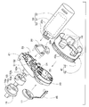
- FIG. 3 An exploded perspective view illustrating the outline of the configuration of the knob rotation mechanism
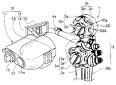
- the endoscope 1 shown in FIG. 1 includes an elongated insertion portion 2, an operation portion 3 which doubles as a grip portion, and a universal cord 4.
- the insertion part 2 has a tip end part 2a, a bending part 2b, and a long flexible tube part 2c having flexibility in order from the tip end side.
- the bending portion 2 b includes a first bending portion 2 b 1 and a second bending portion 2 b 2.
- the first curved portion 2 b 1 is provided on the distal end side of the insertion portion 2.
- the second curved portion 2b2 is connected to the base end of the first curved portion 2b1 via a hook portion (not shown).
- the first bending portion 2b1 is bendable, for example, in the vertical and horizontal directions.
- the second bending portion 2b2 is bendable in the vertical direction.
- the operation unit 3 has a first bending operation device 3a and a second bending operation device 3b.
- the operation unit 3 also serves as a holding unit.
- the main operation unit 3M provided with the first bending operation device 3a, and the base end side of the main operation unit 3M is provided with the second bending operation device 3b.
- the sub operation unit 3S is provided on the operation portion proximal end side which is the opposite side to the insertion portion 2 while being separated from the first bending operation device 3 a.
- the first bending operation device 3a includes, as a bending operation knob, a first bending portion up and down operation knob (hereinafter abbreviated as a first bending up and down knob) 3c and a first bending portion left and right operation knob (hereinafter abbreviated as a first bending left and right knob). 3d, a first curved portion vertically fixed lever (hereinafter abbreviated as a first curved vertically fixed lever) 3e and a first curved portion horizontally fixed knob (hereinafter abbreviated as a first curved left fixed knob) 3f And.
- a first bending portion up and down operation knob hereinafter abbreviated as a first bending up and down knob
- a first bending portion left and right operation knob hereinafter abbreviated as a first bending left and right knob
- the second bending operation device 3b includes a second bending portion up and down operation knob (hereinafter abbreviated as a second bending up and down knob) 3g, which is a bending operation knob, and a second bending portion up and down direction fixing lever (hereinafter, second bending up and down). And 3h) (abbreviated as a fixed lever).
- a second bending portion up and down operation knob hereinafter abbreviated as a second bending up and down knob
- second bending portion up and down direction fixing lever hereinafter, second bending up and down
- And 3h (abbreviated as a fixed lever).
- the first curved upper and lower knobs 3c are turned when the first curved portion 2b1 is bent in the vertical direction.
- the first bending left and right knob 3d is turned when the first bending portion 2b1 is bent in the left-right direction.
- the first curved upper and lower fixed lever 3e is switchable between a free position and a fixed position.
- the first curved left and right fixed knob 3 f can be switched between the free position and the fixed position.
- the first curved upper and lower knob 3c When the first curved upper and lower fixed lever 3e is in the free position, the first curved upper and lower knob 3c is rotatable. At this time, the first bending portion 2b1 is in a state of bending upward or downward along with the turning operation of the first bending portion upper and lower knobs 3c. On the other hand, when the first curved left and right fixed lever 3f is in the free position, the first curved left and right knob 3d can be turned freely. At this time, the first bending portion 2b1 is in a state of bending in the left direction or the right direction along with the turning operation of the first bending left and right knob 3d.
- the second bending upper and lower knob 3g is turned when the second bending portion 2b2 is bent in the vertical direction.
- the second curved upper and lower fixed lever 3h can be switched between the free position and the fixed position.
- the second curved upper and lower fixed lever 3h When the second curved upper and lower fixed lever 3h is in the free position, the second curved upper and lower knob 3g is rotatable. At this time, the second bending portion 2b2 is in a state of being bent upward or downward with the turning operation of the second bending upper and lower knob 3g. On the other hand, when the second curved upper and lower fixed lever 3h is switched to the fixed position, the rotation of the second curved upper and lower knob 3g is restricted. As a result, the bending state of the second bending portion 2b2 in the vertical direction is held in the switching state.
- the reference numeral 5a is an air / water feed button
- the reference numeral 5b is a suction operation button
- the reference numerals 5c, 5d and 5e are remote switches
- the reference numeral 5f is a treatment instrument insertion port
- the reference numeral 5g is a forceps plug.
- the remote switch is a switch for stopping or recording an endoscope image displayed on the screen of a display device (not shown), recording, enlargement of an image, switching of illumination light, and the like. Is assigned the best function.
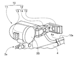
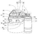
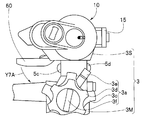
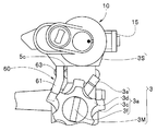
- symbol 10 of FIG. 2A is an external attachment mechanism for endoscopes.
- the endoscope external attachment mechanism 10 is attachable to and detachable from the second curved up-and-down knob 3g provided in the sub operation unit 3S.
- the endoscope external attachment mechanism 10 is an auxiliary mechanism attached to the second curved upper and lower knob 3g to rotate the second curved upper and lower knob 3g by a driving force of a motor (see reference numeral 32 in FIG. 4B described later). It is a department.
- symbol 11 is a storage case and the code
- the case attaching / detaching portion 12 includes a locking portion 13, a hinge portion 14, and a locking claw portion 15.
- the locking portion 13 is fixed at a predetermined position of the housing case 11.
- the hinge portion 14 is substantially L-shaped, and one end thereof is rotatably disposed at a predetermined position of the storage case 11.
- the locking claw 15 is provided at the other end of the L-shaped hinge 14.
- the hinge portion 14 is restricted in its rotational state by engaging and fixing the locking claw portion 15 to the locking portion 13.
- the reference numeral 16 denotes a switching knob, and the reference numeral 17 denotes a curved state display unit, which is provided with a rotation index 17m.
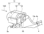
- symbol 4a is a cable attachment, and as shown to FIG. 2B, one or more are provided in the desired position of the universal cord 4, and the electric cable 10e is attached.
- the endoscope external attachment mechanism 10 is disposed in the sub operation section 3S with the storage case 11 covered with the second curved upper and lower knob 3g.
- the locking claw portion 15 is engaged with and fixed to the locking portion 13 by being rotated about the one end side of the hinge portion 14 as a fulcrum, thereby being integrally attached to the sub operation portion 3S.
- reference numeral 60 denotes an operation switch
- reference numeral 61 denotes a switch case
- reference numeral 62 denotes an operator
- reference numeral 63 denotes a dummy switch.
- the housing case 11 of the endoscope external attachment mechanism 10 has a case internal space, and the knob rotation mechanism 20 is accommodated in the case internal space.
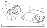
- the housing case 11 is provided with a first through hole 18a in which the switching knob 16 is disposed and a second through hole 18b in which the curved state display unit 17 is disposed.
- the through holes 18a and 18b communicate the case inner space with the outside.
- the knob rotation mechanism 20 will be described with reference to FIGS. 3, 4A and 4B.
- the knob rotation mechanism 20 mainly includes a motor unit 30, a knob rotation unit 40, and a transmission unit 50.
- Reference numeral 21 shown in FIG. 3 to FIG. 4B is a rotation mechanism main body and a mounting member.
- the rotation mechanism portion main body 21 is provided with a motor attachment portion 22, a wheel attachment portion 23, a switching gear attachment portion 24, and the like at predetermined positions.
- Reference numeral 25 denotes a lever recess, which is a hole whose outer shape and depth are formed such that the second curved upper and lower fixed lever 3 h is accommodated.
- Reference numeral 26 denotes a switching gear support member, which has a through hole 26h in which one end of the switching gear shaft 52 on which the switching gear 51 is fixed is disposed.
- the switching gear support member 26 is fixed at a predetermined position of the rotation mechanism main body 21 and pivotally supports one end of the switching gear shaft 52 disposed in the through hole 26 h.
- the motor unit 30 mainly includes a motor case 31, a motor 32 which is a drive source shown by a broken line, and a drive gear 33.
- the motor 32 is disposed in the motor case 31.
- the drive gear 33 is fixed to a motor shaft 32 a protruding from the motor 32.
- the motor case 31 is fixed to the motor attachment portion 22 in a predetermined state as shown in FIG. 4A.
- the knob rotation unit 40 includes a bending wheel 41 and a bending state display unit 17.
- the bending wheel 41 has a knob connection portion 42 and a meshing portion 43 which are ring-shaped members, and the knob connection portion 42 and the meshing portion 43 are integrally fixed.
- the meshing portion 43 is a gear portion having a gear 43g on the outer peripheral surface.
- a plurality of convex portions 44 are arranged in the circumferential direction in the knob connection portion 42.
- the plurality of convex portions 44 are respectively accommodated in the concave portions 3 n located between the plurality of convex portions 3 m of the uneven portion (symbol 3 k in FIG. 2A) of the second curved upper and lower knob 3 g.
- the second curved upper and lower knobs 3g and the curved wheel 41 are integrated by arranging the convex portions 44 in the concave portions 3m. In the integrated state, the second curved upper and lower knobs 3g are rotated in the rotational direction as the curved wheel 41 rotates.
- the curved state display unit 17 is a disk, and a rotation index 17m is provided at a predetermined position on the disk surface.
- Reference numeral 45 denotes a connecting member, and one end of the connecting member 45 is integrally fixed to the back surface of the disc of the bending state display unit 17. The other end of the connecting member 45 is integrally fixed at a predetermined position on the outer peripheral surface of the knob connecting portion 42 of the bending wheel 41.
- the bending state display unit 17 is rotated in the same direction as the bending wheel 41 rotates clockwise or counterclockwise. Therefore, the user can easily determine the bending angle (the amount of bending) of the second bending portion 2b2 by confirming the position of the rotation index 17m.
- the outer diameter Da of the knob connection portion 42 of the bending wheel 41 is set to be smaller than the outer diameter D3g of the second bending upper and lower knob 3g.
- the knob outer diameter D3g of the second curved upper and lower knob 3g is previously set to be the outer periphery outer diameter D3S so as to be disposed inside the outer peripheral surface (denoted as the outer periphery outer diameter D3S) of the sub operating portion 3S as shown in FIG. 2A. It is set smaller.
- the outer peripheral surface of the bending wheel 41 is positioned closer to the center than the outer peripheral surface of the second bending upper and lower knob 3g.
- Reference numeral 11 h is an inner peripheral surface of the knob rotation portion accommodation hole portion of the accommodation case 11.
- the inner diameter of the inner circumferential surface 11h is set in advance to be larger than the outer diameter D3g of the second curved upper and lower knob 3g.
- the thickness t of the storage case 11 is set so that the outer peripheral surface 11 o of the knob rotation portion storage hole 11 h and the outer peripheral surface of the sub operation portion 3 S coincide in surface arrangement.
- the outer peripheral surface 11o of the knob rotation portion accommodation hole 11h may be set to be slightly larger than the outer peripheral surface of the sub operation portion 3S.
- the outer peripheral surface of the bending wheel 41 is set to be disposed closer to the center than the outer peripheral surface of the second curved upper and lower knob 3g. Further, the thickness of the knob rotation portion accommodation hole 11h of the accommodation case 11 is appropriately set, and the diameter of the outer peripheral surface 11o of the knob rotation portion accommodation hole 11h is equal to the diameter of the outer peripheral surface of the sub operation portion 3S It is set slightly larger.
- the outer peripheral surface 11o of the knob rotation portion storage hole 11h of the storage case 11 It is possible to suppress the adverse effect on the operation of the first curved upper and lower knobs 3c, the operation of the first curved left and right knobs 3d, the operation of the first curved upper and lower fixed levers 3e, etc.
- the transmission unit 50 mainly includes the switching gear 51 shown in FIG. 4B, the switching gear shaft 52, the cam ring 53, and the switching knob 16. As described above, the switching gear 51 is fixed to one end side of the switching gear shaft 52.
- the switching gear 51 forms a gear train Gt as shown in FIG. 4D by the gear 43g of the meshing portion 43 of the bending wheel 41 described above and the drive gear 33 fixed to the motor shaft 32a.
- the other end portion of the switching gear shaft 52 is provided with an engagement protrusion 52 a which protrudes in a direction orthogonal to the shaft 52.
- the cam ring 53 is formed with a ring cam groove 53a. Further, a ring protrusion 53 b protrudes from the outer peripheral surface of the cam ring 53.
- the switching knob 16 includes a cylindrical portion 16a, and a cylindrical cam groove 16b is formed in the cylindrical portion 16a.
- the outer peripheral surface side of the cam ring 53 is disposed on the inner peripheral surface side of the cylindrical portion 16 a of the switching knob 16. In this disposition state, the ring projection 53b is disposed in the cylindrical cam groove 16b. On the other hand, on the inner peripheral surface side of the cam ring 53, an engagement protrusion 52a is disposed. In this arrangement state, the engagement projection 52a is disposed in the ring cam groove 53a.
- the ring projection 53b in the cylindrical cam groove 16b is moved along with the rotation of the switching knob 16, and the cam ring 53 is moved in the axial direction of the switching gear shaft 52.
- the engagement projection 52a in the ring cam groove 53a is axially moved.
- the switching gear 51 of the gear train Gt is moved with respect to the axial direction of the switching gear shaft 52 with the switching operation of the switching knob 16 clockwise or counterclockwise.
- the switching gear 51 is switched to a state in which the gear 43c of the meshing portion 43 and the drive gear 33 are in mesh or in a disconnected state.
- the operation switch 60 mainly includes a switch case 61 which is a pivoting member, an operating element 62, and a dummy switch 63 which is an operation member.
- the operation of the dummy switch 63 will be described later.
- the switch case 61 is provided with an operator storage portion 64 and a pin hole 61 h for hinges.
- symbol 6 is a pin for hinges.
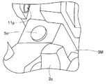
- the hinge pin 6 is disposed in the hinge hole 11 p provided in the housing case 11 and in the hinge pin hole 61 h.
- the switch case 61 formed in a plate shape is rotatably disposed with respect to the storage case 11 with the hinge pin 6 rotatably supporting one end.
- the operating element housing portion 64 is an elongated groove opened on the front surface side of the switch case 61, and the operating element 62 is disposed slidably in the longitudinal direction. Therefore, in the configuration of this figure, the operating element 62 functions as a so-called slide switch.
- the dummy switch 63 is disposed in a direction intersecting with the longitudinal direction of the operation accommodating portion 64 and at a predetermined distance from the accommodating portion 64 in consideration of operability.
- the magnet 65 is arrange
- the sensor 66 outputs a predetermined drive control signal to the motor according to the change in the distance between the N pole and the S pole of the magnet 65.
- the sensor 66 outputs the first drive control signal to the motor 32.
- the motor 32 is rotationally driven, for example, at high speed to rotate the second curved upper and lower knobs 3g in the counterclockwise direction.
- the sensor 66 outputs the third drive control signal to the motor 32.
- the motor 32 is rotationally driven at high speed, for example, to rotate the second curved upper and lower knob 3g clockwise.
- the sensor 66 outputs a fourth drive control signal to the motor 32. Then, the motor 32 is rotationally driven, for example, at a low speed to rotate the second curved up-and-down knob 3g clockwise. Conversely, when the lower end 62b of the operating element 62 is separated from the middle portion by a predetermined distance from the middle portion to the lower side, the sensor 66 outputs the second drive control signal to the motor 32. Then, the motor 32 is rotationally driven, for example, at a low speed to rotate the second curved up-and-down knob 3g in a counterclockwise direction.
- the operating element 62 is a slide switch.
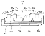
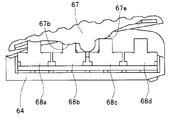
- the operating element may be a seesaw switch 67 that rotates clockwise or counterclockwise around the central convex portion 67c.
- the seesaw switch 67 In the seesaw switch 67, four switch convex portions 67a, 67b, 67d and 67e are provided. Further, a plurality of, for example, four tactile switches 68a, 68b, 68c and 68d are provided in the case housing portion 64.
- the second tactical switch 68b and the third tactical switch 68c are on, and the first tactical switch 68a and the fourth tactical switch 68d are off. At this time, the motor 32 is in a stopped state.
- the fourth tactical switch 68 d is turned on in addition to the third tactical switch 68 c. Then, a third drive control signal is output to the motor 32. Then, the motor 32 is driven at high speed to rotate the second curved upper and lower knob 3g clockwise.
- a drive control signal is output to the motor 32 by sliding or rotating the operating element 62 provided on the operating element 60, and the second bending upper and lower knob 3g is controlled to rotate by the driving force of the motor 32. Do. As a result, the user can bend the second bending portion 2b2 without applying a large load to fingers.
- the speed is two stages of high speed and low speed.
- the motor 32 may be drive-controlled to change the speed in one step, three or more steps, or in steps. Further, the speed may be changed in one step or three or more steps by increasing or decreasing the number of tactical switches and the number of switch convex portions.
- the user may determine in advance whether the second curved upper and lower fixed lever 3h provided on the second curved upper and lower knob 3b is in the free position Check if it is not.
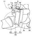
- the user confirms that the second curved upper and lower fixed lever 3h is disposed at the free position, and then, as shown in FIG. 6, the accommodation case 11 of the endoscope external attachment mechanism 10 is provided in the sub operation portion 3S
- the second curved upper and lower knobs 3g are made to face each other.
- the user causes the bending wheel 41 of the knob rotating portion 40 disposed in the case inner space to face the second bending upper and lower knob 3g.
- the user brings the storage case 11 closer to the second curved upper and lower knob 3g.
- the user causes the recess 25 for lever provided in the rotation mechanism main body 21 to face the second curved upper and lower fixed lever 3h, and as shown in FIG. 4C, the second curved upper and lower fixed lever 3h becomes the lever recess 25.
- the housing case 11 is disposed on the second curved upper and lower knobs 3g.
- the convex portion 44 of the knob connection portion 42 is disposed in the concave portion of the second curved upper and lower knob 3g in a predetermined state, and the second curved upper and lower knob 3g And the bending wheel 41 are integrated.
- the rotation mechanism main body 21 is provided with the lever recess 25 for accommodating the lever 3 h when the second curved upper and lower fixed lever 3 h is positioned at the free position.
- the second curved upper and lower knobs 3g reliably rotate clockwise or counterclockwise as the knob connection portion 42 rotates. can do.
- the endoscope external attachment mechanism 10 can not be attached to the auxiliary operation unit 3S in a state where the second curved upper and lower fixed lever 3h is at the fixed position and the rotation is regulated. Therefore, it is possible to prevent the failure by rotating the second curved upper and lower knob 3g whose rotation is restricted by the driving force of the motor 32.
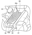
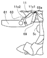
- the remote switch 5c is exposed by the operation switch 60 being disposed at the initial position.
- the user After attaching the housing case 11 to the sub operation unit 3S, the user pushes down the switch case 61 of the rotatable operation switch 60 to the housing case 11 in the direction of the arrow Y7A as shown in FIG. 7A.
- the operation switch 60 of the endoscope external attachment mechanism 10 is disposed at a first position adjacent to the first bending operation device 3a provided in the main operation portion 3M.
- the exposed remote switch 5 c is covered by the switch case 61.
- the remote switch side of the dummy switch 63 is disposed on the remote switch 5c.
- the remote switch 5 c is switch operable by pressing the dummy switch 63 so as to move along the thickness direction of the switch case 61.
- the user grips the main operation unit 3M when performing an endoscopic examination with the endoscope 1 having the endoscope external attachment mechanism 10 attached to the sub operation unit 3S. Then, the user holds the insertion portion 2 with a hand different from the hand holding the main operation portion 3M, and inserts the insertion portion 2 into the body via, for example, the oral cavity.
- the user appropriately causes the first bending portion 2b1 and the second bending portion 2b2 to bend. That is, the user appropriately rotates the first curved up and down knob 3c or the first curved left and right knob 3d of the first bending operation device 3a provided in the main operation portion 3M to vertically move the first curved portion 2b1 or , And the bending operation in the left and right direction etc., while appropriately operating the operation element 62 of the operation switch 60 provided adjacent to the first bending operation device 3a of the main operation portion 3M, bending the second bending portion 2b2 in the vertical direction
- the switch case 61 of the operation switch 60 is rotated between the first position and the second position spaced apart from the first position with respect to the storage case 11 of the endoscope external attachment mechanism 10. It is provided to be movable. Then, the switch spring 61 is provided with the ball spring plunger 69, and the housing case 11 is provided with the first recess 11c1 and the second recess 11c2.
- the engagement state of the ball spring plunger 69 is switched from the first engagement state to the second engagement state.
- the operation switch 60 is provided adjacent to the first bending operation device 3a of the main operation portion 3M, and the rotation operation of the first bending upper and lower knob 3c and the first bending left and right knob 3d of the first bending operation device 3a
- the slide operation and the like of the operation element 62 of the operation switch 60 can be performed with the finger of the user's hand holding the main operation unit 3M.
- the user slightly moves the finger of the hand without touching the remote switch to appropriately bend the first bending portion 2b1 and the second bending portion 2b provided in the bending portion 2b, thereby making the insertion portion 2 Insertion in the deep part of the body can be performed more smoothly.
- the drive control signal may be output from the switch 60 to the motor 32 when the operation switch 60 is in the second engagement state.
- the rotation indicator 17m is provided in the bending state display unit 17, and the bending angle is confirmed.
- the rotation indicator may be the LED lamp 17L shown in FIG.
- the flashing interval of the LED lamp 17L decreases as the amount of bending increases. And when it approaches the maximum bending state, it will be in a lighting state.
- the bending direction is determined by the operation direction of the operating element 62.
- the rotation index 17m is one LED lamp 17L.
- the plurality of LED lamps 17a and 17b may be arranged around the LED lamp 17L. According to this configuration, it can be confirmed that the amount of bending of the bending portion 2b2 increases as the number of lighting of the LED lamp increases.
- the endoscope external attachment mechanism 10 is attached to the sub operation unit 3S so that the second bending portion 2b2 is bent without applying a large load to the user's finger.
- the knob to which the endoscope external attachment mechanism 10 is attached is not limited to the second curved up-and-down knob 3g provided in the sub operation unit 3S, and the first curvature provided in the main operation portion 3M
- the left and right knobs 3d or both the first curved upper and lower knobs 3c and the first curved left and right knobs 3d may be used.
- an external mechanism for an endoscope that is easy to attach to and dismount from the operation unit, and does not affect the layout or the operability of the endoscope in the attached state.
Landscapes
- Health & Medical Sciences (AREA)
- Life Sciences & Earth Sciences (AREA)
- Surgery (AREA)
- Physics & Mathematics (AREA)
- Engineering & Computer Science (AREA)
- Optics & Photonics (AREA)
- Medical Informatics (AREA)
- General Health & Medical Sciences (AREA)
- Pathology (AREA)
- Nuclear Medicine, Radiotherapy & Molecular Imaging (AREA)
- Biomedical Technology (AREA)
- Heart & Thoracic Surgery (AREA)
- Biophysics (AREA)
- Molecular Biology (AREA)
- Animal Behavior & Ethology (AREA)
- Radiology & Medical Imaging (AREA)
- Public Health (AREA)
- Veterinary Medicine (AREA)
- Signal Processing (AREA)
- Rehabilitation Therapy (AREA)
- Astronomy & Astrophysics (AREA)
- General Physics & Mathematics (AREA)
- Instruments For Viewing The Inside Of Hollow Bodies (AREA)
- Endoscopes (AREA)
Abstract
L'invention concerne un mécanisme externe (10) pour endoscope comportant: une roue (41) se mettant en prise avec un deuxième bouton (3g) d'actionnement vertical incurvé d'un deuxième dispositif (3b) d'actionnement incurvé fixé sur une partie (3) d'actionnement de l'endoscope (1); un moteur (32) générant une force d'entraînement destinée à faire pivoter la roue (41); un commutateur d'actionnement (60) émettant en sortie un signal de commande d'entraînement du moteur (32); un boîtier (11) dans lequel sont logés la roue (41) et le moteur (32); une partie (12) fixation amovible du boîtier destinée à fixer le boîtier (11) de manière amovible sur une partie (3) d'actionnement; un boîtier (61) de commutateur monté sur le boîtier (11), lequel boîtier de commutateur peut pivoter entre une première position dans laquelle il recouvre une partie de la partie (3) d'actionnement et une deuxième position éloignée de la première position. Le commutateur d'actionnement comporte un élément d'actionnement disposé sur une partie logement située sur un élément rotatif, et par déplacement de l'élément d'actionnement côté surface de l'élément rotatif, le signal de commande d'entraînement de la source d'entraînement est émis en sortie.
Priority Applications (3)
| Application Number | Priority Date | Filing Date | Title |
|---|---|---|---|
| CN201880086596.8A CN111683578B (zh) | 2017-12-18 | 2018-12-13 | 内窥镜用外置机构和内窥镜系统 |
| JP2019561013A JP6792725B2 (ja) | 2017-12-18 | 2018-12-13 | 内視鏡用外付機構および内視鏡システム |
| US16/903,824 US11432708B2 (en) | 2017-12-18 | 2020-06-17 | External mechanism for endoscope and endoscope system |
Applications Claiming Priority (2)
| Application Number | Priority Date | Filing Date | Title |
|---|---|---|---|
| JP2017241492 | 2017-12-18 | ||
| JP2017-241492 | 2017-12-18 |
Related Child Applications (1)
| Application Number | Title | Priority Date | Filing Date |
|---|---|---|---|
| US16/903,824 Continuation US11432708B2 (en) | 2017-12-18 | 2020-06-17 | External mechanism for endoscope and endoscope system |
Publications (1)
| Publication Number | Publication Date |
|---|---|
| WO2019124207A1 true WO2019124207A1 (fr) | 2019-06-27 |
Family
ID=66993533
Family Applications (1)
| Application Number | Title | Priority Date | Filing Date |
|---|---|---|---|
| PCT/JP2018/045837 Ceased WO2019124207A1 (fr) | 2017-12-18 | 2018-12-13 | Mécanisme externe pour endoscope |
Country Status (4)
| Country | Link |
|---|---|
| US (1) | US11432708B2 (fr) |
| JP (1) | JP6792725B2 (fr) |
| CN (1) | CN111683578B (fr) |
| WO (1) | WO2019124207A1 (fr) |
Families Citing this family (1)
| Publication number | Priority date | Publication date | Assignee | Title |
|---|---|---|---|---|
| JP2021180694A (ja) * | 2018-05-29 | 2021-11-25 | オリンパス株式会社 | 内視鏡用外付機構 |
Citations (5)
| Publication number | Priority date | Publication date | Assignee | Title |
|---|---|---|---|---|
| JPH0255907U (fr) * | 1988-10-15 | 1990-04-23 | ||
| JPH05300873A (ja) * | 1992-04-28 | 1993-11-16 | Olympus Optical Co Ltd | 内視鏡用湾曲制御装置 |
| JPH1132977A (ja) * | 1997-07-17 | 1999-02-09 | Olympus Optical Co Ltd | 内視鏡装置 |
| WO2010047223A1 (fr) * | 2008-10-22 | 2010-04-29 | オリンパスメディカルシステムズ株式会社 | Endoscope électriquement pliable |
| WO2012063880A1 (fr) * | 2010-11-10 | 2012-05-18 | オリンパスメディカルシステムズ株式会社 | Endoscope |
Family Cites Families (7)
| Publication number | Priority date | Publication date | Assignee | Title |
|---|---|---|---|---|
| JP2000089131A (ja) * | 1998-09-16 | 2000-03-31 | Olympus Optical Co Ltd | 電子内視鏡装置 |
| JP4383127B2 (ja) * | 2003-08-26 | 2009-12-16 | オリンパス株式会社 | 内視鏡 |
| JP4855867B2 (ja) | 2006-08-22 | 2012-01-18 | オリンパスメディカルシステムズ株式会社 | 内視鏡 |
| JP5330625B1 (ja) * | 2011-09-26 | 2013-10-30 | オリンパスメディカルシステムズ株式会社 | 内視鏡 |
| WO2013141216A1 (fr) * | 2012-03-23 | 2013-09-26 | オリンパスメディカルシステムズ株式会社 | Dispositif d'insertion |
| DE102015004546B4 (de) * | 2015-04-08 | 2023-05-04 | Schölly Fiberoptic GmbH | Medizinisches Instrument |
| WO2019124206A1 (fr) * | 2017-12-18 | 2019-06-27 | オリンパス株式会社 | Mécanisme externe pour endoscope |
-
2018
- 2018-12-13 CN CN201880086596.8A patent/CN111683578B/zh active Active
- 2018-12-13 JP JP2019561013A patent/JP6792725B2/ja active Active
- 2018-12-13 WO PCT/JP2018/045837 patent/WO2019124207A1/fr not_active Ceased
-
2020
- 2020-06-17 US US16/903,824 patent/US11432708B2/en active Active
Patent Citations (5)
| Publication number | Priority date | Publication date | Assignee | Title |
|---|---|---|---|---|
| JPH0255907U (fr) * | 1988-10-15 | 1990-04-23 | ||
| JPH05300873A (ja) * | 1992-04-28 | 1993-11-16 | Olympus Optical Co Ltd | 内視鏡用湾曲制御装置 |
| JPH1132977A (ja) * | 1997-07-17 | 1999-02-09 | Olympus Optical Co Ltd | 内視鏡装置 |
| WO2010047223A1 (fr) * | 2008-10-22 | 2010-04-29 | オリンパスメディカルシステムズ株式会社 | Endoscope électriquement pliable |
| WO2012063880A1 (fr) * | 2010-11-10 | 2012-05-18 | オリンパスメディカルシステムズ株式会社 | Endoscope |
Also Published As
| Publication number | Publication date |
|---|---|
| JP6792725B2 (ja) | 2020-11-25 |
| JPWO2019124207A1 (ja) | 2020-08-20 |
| CN111683578A (zh) | 2020-09-18 |
| US11432708B2 (en) | 2022-09-06 |
| CN111683578B (zh) | 2023-08-25 |
| US20200397226A1 (en) | 2020-12-24 |
Similar Documents
| Publication | Publication Date | Title |
|---|---|---|
| JP6779392B2 (ja) | 内視鏡用外付機構及び内視鏡システム | |
| US8100825B2 (en) | Endoscope and supportive member for bending operation of the same | |
| US8409079B2 (en) | Electric bending operation device and medical treatment system including electric bending operation device | |
| US20120302829A1 (en) | Endoscope | |
| JP6322775B1 (ja) | 内視鏡システム | |
| CN100496376C (zh) | 内窥镜 | |
| CN101449957A (zh) | 保持用缆线、具有保持用缆线的观察装置以及内窥镜装置 | |
| CN111669999B (zh) | 内窥镜用外置机构和内窥镜系统 | |
| WO2019230087A1 (fr) | Mécanisme externe d'endoscope | |
| WO2019124207A1 (fr) | Mécanisme externe pour endoscope | |
| US11633086B2 (en) | External mechanism for endoscope, and endoscope apparatus | |
| WO2019225089A1 (fr) | Mécanisme externe pour endoscope | |
| WO2019124208A1 (fr) | Mécanisme externe pour endoscope | |
| WO2019234990A1 (fr) | Mécanisme externe pour endoscope | |
| JP4445779B2 (ja) | 内視鏡及び内視鏡用湾曲操作補助部材 | |
| JP5078260B2 (ja) | 体腔内検査装置 | |
| JP2005152365A (ja) | 内視鏡システム | |
| JP2009208711A (ja) | ダイヤル式コントロール操作装置 |
Legal Events
| Date | Code | Title | Description |
|---|---|---|---|
| 121 | Ep: the epo has been informed by wipo that ep was designated in this application |
Ref document number: 18891990 Country of ref document: EP Kind code of ref document: A1 |
|
| ENP | Entry into the national phase |
Ref document number: 2019561013 Country of ref document: JP Kind code of ref document: A |
|
| NENP | Non-entry into the national phase |
Ref country code: DE |
|
| 122 | Ep: pct application non-entry in european phase |
Ref document number: 18891990 Country of ref document: EP Kind code of ref document: A1 |