WO2019124329A1 - Dispositif de cyclage de fluide frigorigène - Google Patents
Dispositif de cyclage de fluide frigorigène Download PDFInfo
- Publication number
- WO2019124329A1 WO2019124329A1 PCT/JP2018/046434 JP2018046434W WO2019124329A1 WO 2019124329 A1 WO2019124329 A1 WO 2019124329A1 JP 2018046434 W JP2018046434 W JP 2018046434W WO 2019124329 A1 WO2019124329 A1 WO 2019124329A1
- Authority
- WO
- WIPO (PCT)
- Prior art keywords
- point
- hfo
- refrigerant
- coordinates
- line segment
- Prior art date
- Legal status (The legal status is an assumption and is not a legal conclusion. Google has not performed a legal analysis and makes no representation as to the accuracy of the status listed.)
- Ceased
Links
Images













Classifications
-
- C—CHEMISTRY; METALLURGY
- C09—DYES; PAINTS; POLISHES; NATURAL RESINS; ADHESIVES; COMPOSITIONS NOT OTHERWISE PROVIDED FOR; APPLICATIONS OF MATERIALS NOT OTHERWISE PROVIDED FOR
- C09K—MATERIALS FOR MISCELLANEOUS APPLICATIONS, NOT PROVIDED FOR ELSEWHERE
- C09K5/00—Heat-transfer, heat-exchange or heat-storage materials, e.g. refrigerants; Materials for the production of heat or cold by chemical reactions other than by combustion
- C09K5/02—Materials undergoing a change of physical state when used
- C09K5/04—Materials undergoing a change of physical state when used the change of state being from liquid to vapour or vice versa
-
- C—CHEMISTRY; METALLURGY
- C09—DYES; PAINTS; POLISHES; NATURAL RESINS; ADHESIVES; COMPOSITIONS NOT OTHERWISE PROVIDED FOR; APPLICATIONS OF MATERIALS NOT OTHERWISE PROVIDED FOR
- C09K—MATERIALS FOR MISCELLANEOUS APPLICATIONS, NOT PROVIDED FOR ELSEWHERE
- C09K5/00—Heat-transfer, heat-exchange or heat-storage materials, e.g. refrigerants; Materials for the production of heat or cold by chemical reactions other than by combustion
- C09K5/02—Materials undergoing a change of physical state when used
- C09K5/04—Materials undergoing a change of physical state when used the change of state being from liquid to vapour or vice versa
- C09K5/041—Materials undergoing a change of physical state when used the change of state being from liquid to vapour or vice versa for compression-type refrigeration systems
- C09K5/044—Materials undergoing a change of physical state when used the change of state being from liquid to vapour or vice versa for compression-type refrigeration systems comprising halogenated compounds
- C09K5/045—Materials undergoing a change of physical state when used the change of state being from liquid to vapour or vice versa for compression-type refrigeration systems comprising halogenated compounds containing only fluorine as halogen
-
- C—CHEMISTRY; METALLURGY
- C10—PETROLEUM, GAS OR COKE INDUSTRIES; TECHNICAL GASES CONTAINING CARBON MONOXIDE; FUELS; LUBRICANTS; PEAT
- C10M—LUBRICATING COMPOSITIONS; USE OF CHEMICAL SUBSTANCES EITHER ALONE OR AS LUBRICATING INGREDIENTS IN A LUBRICATING COMPOSITION
- C10M169/00—Lubricating compositions characterised by containing as components a mixture of at least two types of ingredient selected from base-materials, thickeners or additives, covered by the preceding groups, each of these compounds being essential
- C10M169/04—Mixtures of base-materials and additives
-
- C—CHEMISTRY; METALLURGY
- C10—PETROLEUM, GAS OR COKE INDUSTRIES; TECHNICAL GASES CONTAINING CARBON MONOXIDE; FUELS; LUBRICANTS; PEAT
- C10M—LUBRICATING COMPOSITIONS; USE OF CHEMICAL SUBSTANCES EITHER ALONE OR AS LUBRICATING INGREDIENTS IN A LUBRICATING COMPOSITION
- C10M171/00—Lubricating compositions characterised by purely physical criteria, e.g. containing as base-material, thickener or additive, ingredients which are characterised exclusively by their numerically specified physical properties, i.e. containing ingredients which are physically well-defined but for which the chemical nature is either unspecified or only very vaguely indicated
- C10M171/02—Specified values of viscosity or viscosity index
-
- F—MECHANICAL ENGINEERING; LIGHTING; HEATING; WEAPONS; BLASTING
- F24—HEATING; RANGES; VENTILATING
- F24F—AIR-CONDITIONING; AIR-HUMIDIFICATION; VENTILATION; USE OF AIR CURRENTS FOR SCREENING
- F24F1/00—Room units for air-conditioning, e.g. separate or self-contained units or units receiving primary air from a central station
- F24F1/0007—Indoor units, e.g. fan coil units
- F24F1/0059—Indoor units, e.g. fan coil units characterised by heat exchangers
-
- F—MECHANICAL ENGINEERING; LIGHTING; HEATING; WEAPONS; BLASTING
- F24—HEATING; RANGES; VENTILATING
- F24F—AIR-CONDITIONING; AIR-HUMIDIFICATION; VENTILATION; USE OF AIR CURRENTS FOR SCREENING
- F24F1/00—Room units for air-conditioning, e.g. separate or self-contained units or units receiving primary air from a central station
- F24F1/0007—Indoor units, e.g. fan coil units
- F24F1/0059—Indoor units, e.g. fan coil units characterised by heat exchangers
- F24F1/0063—Indoor units, e.g. fan coil units characterised by heat exchangers by the mounting or arrangement of the heat exchangers
-
- F—MECHANICAL ENGINEERING; LIGHTING; HEATING; WEAPONS; BLASTING
- F24—HEATING; RANGES; VENTILATING
- F24F—AIR-CONDITIONING; AIR-HUMIDIFICATION; VENTILATION; USE OF AIR CURRENTS FOR SCREENING
- F24F1/00—Room units for air-conditioning, e.g. separate or self-contained units or units receiving primary air from a central station
- F24F1/0007—Indoor units, e.g. fan coil units
- F24F1/0059—Indoor units, e.g. fan coil units characterised by heat exchangers
- F24F1/0067—Indoor units, e.g. fan coil units characterised by heat exchangers by the shape of the heat exchangers or of parts thereof, e.g. of their fins
-
- F—MECHANICAL ENGINEERING; LIGHTING; HEATING; WEAPONS; BLASTING
- F24—HEATING; RANGES; VENTILATING
- F24F—AIR-CONDITIONING; AIR-HUMIDIFICATION; VENTILATION; USE OF AIR CURRENTS FOR SCREENING
- F24F1/00—Room units for air-conditioning, e.g. separate or self-contained units or units receiving primary air from a central station
- F24F1/06—Separate outdoor units, e.g. outdoor unit to be linked to a separate room comprising a compressor and a heat exchanger
- F24F1/14—Heat exchangers specially adapted for separate outdoor units
-
- F—MECHANICAL ENGINEERING; LIGHTING; HEATING; WEAPONS; BLASTING
- F24—HEATING; RANGES; VENTILATING
- F24F—AIR-CONDITIONING; AIR-HUMIDIFICATION; VENTILATION; USE OF AIR CURRENTS FOR SCREENING
- F24F1/00—Room units for air-conditioning, e.g. separate or self-contained units or units receiving primary air from a central station
- F24F1/06—Separate outdoor units, e.g. outdoor unit to be linked to a separate room comprising a compressor and a heat exchanger
- F24F1/20—Electric components for separate outdoor units
- F24F1/24—Cooling of electric components
-
- F—MECHANICAL ENGINEERING; LIGHTING; HEATING; WEAPONS; BLASTING
- F24—HEATING; RANGES; VENTILATING
- F24F—AIR-CONDITIONING; AIR-HUMIDIFICATION; VENTILATION; USE OF AIR CURRENTS FOR SCREENING
- F24F1/00—Room units for air-conditioning, e.g. separate or self-contained units or units receiving primary air from a central station
- F24F1/06—Separate outdoor units, e.g. outdoor unit to be linked to a separate room comprising a compressor and a heat exchanger
- F24F1/26—Refrigerant piping
- F24F1/32—Refrigerant piping for connecting the separate outdoor units to indoor units
-
- F—MECHANICAL ENGINEERING; LIGHTING; HEATING; WEAPONS; BLASTING
- F24—HEATING; RANGES; VENTILATING
- F24F—AIR-CONDITIONING; AIR-HUMIDIFICATION; VENTILATION; USE OF AIR CURRENTS FOR SCREENING
- F24F1/00—Room units for air-conditioning, e.g. separate or self-contained units or units receiving primary air from a central station
- F24F1/06—Separate outdoor units, e.g. outdoor unit to be linked to a separate room comprising a compressor and a heat exchanger
- F24F1/26—Refrigerant piping
- F24F1/34—Protection means thereof, e.g. covers for refrigerant pipes
-
- F—MECHANICAL ENGINEERING; LIGHTING; HEATING; WEAPONS; BLASTING
- F24—HEATING; RANGES; VENTILATING
- F24F—AIR-CONDITIONING; AIR-HUMIDIFICATION; VENTILATION; USE OF AIR CURRENTS FOR SCREENING
- F24F1/00—Room units for air-conditioning, e.g. separate or self-contained units or units receiving primary air from a central station
- F24F1/06—Separate outdoor units, e.g. outdoor unit to be linked to a separate room comprising a compressor and a heat exchanger
- F24F1/38—Fan details of outdoor units, e.g. bell-mouth shaped inlets or fan mountings
-
- F—MECHANICAL ENGINEERING; LIGHTING; HEATING; WEAPONS; BLASTING
- F24—HEATING; RANGES; VENTILATING
- F24F—AIR-CONDITIONING; AIR-HUMIDIFICATION; VENTILATION; USE OF AIR CURRENTS FOR SCREENING
- F24F11/00—Control or safety arrangements
- F24F11/62—Control or safety arrangements characterised by the type of control or by internal processing, e.g. using fuzzy logic, adaptive control or estimation of values
- F24F11/63—Electronic processing
- F24F11/65—Electronic processing for selecting an operating mode
-
- F—MECHANICAL ENGINEERING; LIGHTING; HEATING; WEAPONS; BLASTING
- F24—HEATING; RANGES; VENTILATING
- F24F—AIR-CONDITIONING; AIR-HUMIDIFICATION; VENTILATION; USE OF AIR CURRENTS FOR SCREENING
- F24F11/00—Control or safety arrangements
- F24F11/88—Electrical aspects, e.g. circuits
-
- F—MECHANICAL ENGINEERING; LIGHTING; HEATING; WEAPONS; BLASTING
- F24—HEATING; RANGES; VENTILATING
- F24F—AIR-CONDITIONING; AIR-HUMIDIFICATION; VENTILATION; USE OF AIR CURRENTS FOR SCREENING
- F24F13/00—Details common to, or for air-conditioning, air-humidification, ventilation or use of air currents for screening
- F24F13/30—Arrangement or mounting of heat-exchangers
-
- F—MECHANICAL ENGINEERING; LIGHTING; HEATING; WEAPONS; BLASTING
- F24—HEATING; RANGES; VENTILATING
- F24F—AIR-CONDITIONING; AIR-HUMIDIFICATION; VENTILATION; USE OF AIR CURRENTS FOR SCREENING
- F24F3/00—Air-conditioning systems in which conditioned primary air is supplied from one or more central stations to distributing units in the rooms or spaces where it may receive secondary treatment; Apparatus specially designed for such systems
- F24F3/044—Systems in which all treatment is given in the central station, i.e. all-air systems
- F24F3/048—Systems in which all treatment is given in the central station, i.e. all-air systems with temperature control at constant rate of air-flow
- F24F3/052—Multiple duct systems, e.g. systems in which hot and cold air are supplied by separate circuits from the central station to mixing chambers in the spaces to be conditioned
-
- F—MECHANICAL ENGINEERING; LIGHTING; HEATING; WEAPONS; BLASTING
- F24—HEATING; RANGES; VENTILATING
- F24F—AIR-CONDITIONING; AIR-HUMIDIFICATION; VENTILATION; USE OF AIR CURRENTS FOR SCREENING
- F24F5/00—Air-conditioning systems or apparatus not covered by F24F1/00 or F24F3/00, e.g. using solar heat or combined with household units such as an oven or water heater
-
- F—MECHANICAL ENGINEERING; LIGHTING; HEATING; WEAPONS; BLASTING
- F24—HEATING; RANGES; VENTILATING
- F24F—AIR-CONDITIONING; AIR-HUMIDIFICATION; VENTILATION; USE OF AIR CURRENTS FOR SCREENING
- F24F5/00—Air-conditioning systems or apparatus not covered by F24F1/00 or F24F3/00, e.g. using solar heat or combined with household units such as an oven or water heater
- F24F5/0007—Air-conditioning systems or apparatus not covered by F24F1/00 or F24F3/00, e.g. using solar heat or combined with household units such as an oven or water heater cooling apparatus specially adapted for use in air-conditioning
- F24F5/001—Compression cycle type
-
- F—MECHANICAL ENGINEERING; LIGHTING; HEATING; WEAPONS; BLASTING
- F24—HEATING; RANGES; VENTILATING
- F24H—FLUID HEATERS, e.g. WATER OR AIR HEATERS, HAVING HEAT-GENERATING MEANS, e.g. HEAT PUMPS, IN GENERAL
- F24H1/00—Water heaters, e.g. boilers, continuous-flow heaters or water-storage heaters
- F24H1/0018—Water heaters, e.g. boilers, continuous-flow heaters or water-storage heaters using electric energy supply
-
- F—MECHANICAL ENGINEERING; LIGHTING; HEATING; WEAPONS; BLASTING
- F24—HEATING; RANGES; VENTILATING
- F24H—FLUID HEATERS, e.g. WATER OR AIR HEATERS, HAVING HEAT-GENERATING MEANS, e.g. HEAT PUMPS, IN GENERAL
- F24H4/00—Fluid heaters characterised by the use of heat pumps
- F24H4/02—Water heaters
-
- F—MECHANICAL ENGINEERING; LIGHTING; HEATING; WEAPONS; BLASTING
- F25—REFRIGERATION OR COOLING; COMBINED HEATING AND REFRIGERATION SYSTEMS; HEAT PUMP SYSTEMS; MANUFACTURE OR STORAGE OF ICE; LIQUEFACTION SOLIDIFICATION OF GASES
- F25B—REFRIGERATION MACHINES, PLANTS OR SYSTEMS; COMBINED HEATING AND REFRIGERATION SYSTEMS; HEAT PUMP SYSTEMS
- F25B1/00—Compression machines, plants or systems with non-reversible cycle
-
- F—MECHANICAL ENGINEERING; LIGHTING; HEATING; WEAPONS; BLASTING
- F25—REFRIGERATION OR COOLING; COMBINED HEATING AND REFRIGERATION SYSTEMS; HEAT PUMP SYSTEMS; MANUFACTURE OR STORAGE OF ICE; LIQUEFACTION SOLIDIFICATION OF GASES
- F25B—REFRIGERATION MACHINES, PLANTS OR SYSTEMS; COMBINED HEATING AND REFRIGERATION SYSTEMS; HEAT PUMP SYSTEMS
- F25B1/00—Compression machines, plants or systems with non-reversible cycle
- F25B1/04—Compression machines, plants or systems with non-reversible cycle with compressor of rotary type
-
- F—MECHANICAL ENGINEERING; LIGHTING; HEATING; WEAPONS; BLASTING
- F25—REFRIGERATION OR COOLING; COMBINED HEATING AND REFRIGERATION SYSTEMS; HEAT PUMP SYSTEMS; MANUFACTURE OR STORAGE OF ICE; LIQUEFACTION SOLIDIFICATION OF GASES
- F25B—REFRIGERATION MACHINES, PLANTS OR SYSTEMS; COMBINED HEATING AND REFRIGERATION SYSTEMS; HEAT PUMP SYSTEMS
- F25B13/00—Compression machines, plants or systems, with reversible cycle
-
- F—MECHANICAL ENGINEERING; LIGHTING; HEATING; WEAPONS; BLASTING
- F25—REFRIGERATION OR COOLING; COMBINED HEATING AND REFRIGERATION SYSTEMS; HEAT PUMP SYSTEMS; MANUFACTURE OR STORAGE OF ICE; LIQUEFACTION SOLIDIFICATION OF GASES
- F25B—REFRIGERATION MACHINES, PLANTS OR SYSTEMS; COMBINED HEATING AND REFRIGERATION SYSTEMS; HEAT PUMP SYSTEMS
- F25B21/00—Machines, plants or systems, using electric or magnetic effects
-
- F—MECHANICAL ENGINEERING; LIGHTING; HEATING; WEAPONS; BLASTING
- F25—REFRIGERATION OR COOLING; COMBINED HEATING AND REFRIGERATION SYSTEMS; HEAT PUMP SYSTEMS; MANUFACTURE OR STORAGE OF ICE; LIQUEFACTION SOLIDIFICATION OF GASES
- F25B—REFRIGERATION MACHINES, PLANTS OR SYSTEMS; COMBINED HEATING AND REFRIGERATION SYSTEMS; HEAT PUMP SYSTEMS
- F25B29/00—Combined heating and refrigeration systems, e.g. operating alternately or simultaneously
-
- F—MECHANICAL ENGINEERING; LIGHTING; HEATING; WEAPONS; BLASTING
- F25—REFRIGERATION OR COOLING; COMBINED HEATING AND REFRIGERATION SYSTEMS; HEAT PUMP SYSTEMS; MANUFACTURE OR STORAGE OF ICE; LIQUEFACTION SOLIDIFICATION OF GASES
- F25B—REFRIGERATION MACHINES, PLANTS OR SYSTEMS; COMBINED HEATING AND REFRIGERATION SYSTEMS; HEAT PUMP SYSTEMS
- F25B29/00—Combined heating and refrigeration systems, e.g. operating alternately or simultaneously
- F25B29/003—Combined heating and refrigeration systems, e.g. operating alternately or simultaneously of the compression type system
-
- F—MECHANICAL ENGINEERING; LIGHTING; HEATING; WEAPONS; BLASTING
- F25—REFRIGERATION OR COOLING; COMBINED HEATING AND REFRIGERATION SYSTEMS; HEAT PUMP SYSTEMS; MANUFACTURE OR STORAGE OF ICE; LIQUEFACTION SOLIDIFICATION OF GASES
- F25B—REFRIGERATION MACHINES, PLANTS OR SYSTEMS; COMBINED HEATING AND REFRIGERATION SYSTEMS; HEAT PUMP SYSTEMS
- F25B31/00—Compressor arrangements
- F25B31/002—Lubrication
-
- F—MECHANICAL ENGINEERING; LIGHTING; HEATING; WEAPONS; BLASTING
- F25—REFRIGERATION OR COOLING; COMBINED HEATING AND REFRIGERATION SYSTEMS; HEAT PUMP SYSTEMS; MANUFACTURE OR STORAGE OF ICE; LIQUEFACTION SOLIDIFICATION OF GASES
- F25B—REFRIGERATION MACHINES, PLANTS OR SYSTEMS; COMBINED HEATING AND REFRIGERATION SYSTEMS; HEAT PUMP SYSTEMS
- F25B31/00—Compressor arrangements
- F25B31/006—Cooling of compressor or motor
-
- F—MECHANICAL ENGINEERING; LIGHTING; HEATING; WEAPONS; BLASTING
- F25—REFRIGERATION OR COOLING; COMBINED HEATING AND REFRIGERATION SYSTEMS; HEAT PUMP SYSTEMS; MANUFACTURE OR STORAGE OF ICE; LIQUEFACTION SOLIDIFICATION OF GASES
- F25B—REFRIGERATION MACHINES, PLANTS OR SYSTEMS; COMBINED HEATING AND REFRIGERATION SYSTEMS; HEAT PUMP SYSTEMS
- F25B31/00—Compressor arrangements
- F25B31/02—Compressor arrangements of motor-compressor units
- F25B31/026—Compressor arrangements of motor-compressor units with compressor of rotary type
-
- F—MECHANICAL ENGINEERING; LIGHTING; HEATING; WEAPONS; BLASTING
- F25—REFRIGERATION OR COOLING; COMBINED HEATING AND REFRIGERATION SYSTEMS; HEAT PUMP SYSTEMS; MANUFACTURE OR STORAGE OF ICE; LIQUEFACTION SOLIDIFICATION OF GASES
- F25B—REFRIGERATION MACHINES, PLANTS OR SYSTEMS; COMBINED HEATING AND REFRIGERATION SYSTEMS; HEAT PUMP SYSTEMS
- F25B39/00—Evaporators; Condensers
-
- F—MECHANICAL ENGINEERING; LIGHTING; HEATING; WEAPONS; BLASTING
- F25—REFRIGERATION OR COOLING; COMBINED HEATING AND REFRIGERATION SYSTEMS; HEAT PUMP SYSTEMS; MANUFACTURE OR STORAGE OF ICE; LIQUEFACTION SOLIDIFICATION OF GASES
- F25B—REFRIGERATION MACHINES, PLANTS OR SYSTEMS; COMBINED HEATING AND REFRIGERATION SYSTEMS; HEAT PUMP SYSTEMS
- F25B39/00—Evaporators; Condensers
- F25B39/02—Evaporators
- F25B39/028—Evaporators having distributing means
-
- F—MECHANICAL ENGINEERING; LIGHTING; HEATING; WEAPONS; BLASTING
- F25—REFRIGERATION OR COOLING; COMBINED HEATING AND REFRIGERATION SYSTEMS; HEAT PUMP SYSTEMS; MANUFACTURE OR STORAGE OF ICE; LIQUEFACTION SOLIDIFICATION OF GASES
- F25B—REFRIGERATION MACHINES, PLANTS OR SYSTEMS; COMBINED HEATING AND REFRIGERATION SYSTEMS; HEAT PUMP SYSTEMS
- F25B41/00—Fluid-circulation arrangements
-
- F—MECHANICAL ENGINEERING; LIGHTING; HEATING; WEAPONS; BLASTING
- F25—REFRIGERATION OR COOLING; COMBINED HEATING AND REFRIGERATION SYSTEMS; HEAT PUMP SYSTEMS; MANUFACTURE OR STORAGE OF ICE; LIQUEFACTION SOLIDIFICATION OF GASES
- F25B—REFRIGERATION MACHINES, PLANTS OR SYSTEMS; COMBINED HEATING AND REFRIGERATION SYSTEMS; HEAT PUMP SYSTEMS
- F25B41/00—Fluid-circulation arrangements
- F25B41/30—Expansion means; Dispositions thereof
- F25B41/31—Expansion valves
- F25B41/34—Expansion valves with the valve member being actuated by electric means, e.g. by piezoelectric actuators
-
- F—MECHANICAL ENGINEERING; LIGHTING; HEATING; WEAPONS; BLASTING
- F25—REFRIGERATION OR COOLING; COMBINED HEATING AND REFRIGERATION SYSTEMS; HEAT PUMP SYSTEMS; MANUFACTURE OR STORAGE OF ICE; LIQUEFACTION SOLIDIFICATION OF GASES
- F25B—REFRIGERATION MACHINES, PLANTS OR SYSTEMS; COMBINED HEATING AND REFRIGERATION SYSTEMS; HEAT PUMP SYSTEMS
- F25B45/00—Arrangements for charging or discharging refrigerant
-
- F—MECHANICAL ENGINEERING; LIGHTING; HEATING; WEAPONS; BLASTING
- F25—REFRIGERATION OR COOLING; COMBINED HEATING AND REFRIGERATION SYSTEMS; HEAT PUMP SYSTEMS; MANUFACTURE OR STORAGE OF ICE; LIQUEFACTION SOLIDIFICATION OF GASES
- F25B—REFRIGERATION MACHINES, PLANTS OR SYSTEMS; COMBINED HEATING AND REFRIGERATION SYSTEMS; HEAT PUMP SYSTEMS
- F25B49/00—Arrangement or mounting of control or safety devices
- F25B49/02—Arrangement or mounting of control or safety devices for compression type machines, plants or systems
-
- F—MECHANICAL ENGINEERING; LIGHTING; HEATING; WEAPONS; BLASTING
- F25—REFRIGERATION OR COOLING; COMBINED HEATING AND REFRIGERATION SYSTEMS; HEAT PUMP SYSTEMS; MANUFACTURE OR STORAGE OF ICE; LIQUEFACTION SOLIDIFICATION OF GASES
- F25B—REFRIGERATION MACHINES, PLANTS OR SYSTEMS; COMBINED HEATING AND REFRIGERATION SYSTEMS; HEAT PUMP SYSTEMS
- F25B49/00—Arrangement or mounting of control or safety devices
- F25B49/02—Arrangement or mounting of control or safety devices for compression type machines, plants or systems
- F25B49/022—Compressor control arrangements
-
- F—MECHANICAL ENGINEERING; LIGHTING; HEATING; WEAPONS; BLASTING
- F25—REFRIGERATION OR COOLING; COMBINED HEATING AND REFRIGERATION SYSTEMS; HEAT PUMP SYSTEMS; MANUFACTURE OR STORAGE OF ICE; LIQUEFACTION SOLIDIFICATION OF GASES
- F25B—REFRIGERATION MACHINES, PLANTS OR SYSTEMS; COMBINED HEATING AND REFRIGERATION SYSTEMS; HEAT PUMP SYSTEMS
- F25B5/00—Compression machines, plants or systems, with several evaporator circuits, e.g. for varying refrigerating capacity
- F25B5/04—Compression machines, plants or systems, with several evaporator circuits, e.g. for varying refrigerating capacity arranged in series
-
- F—MECHANICAL ENGINEERING; LIGHTING; HEATING; WEAPONS; BLASTING
- F25—REFRIGERATION OR COOLING; COMBINED HEATING AND REFRIGERATION SYSTEMS; HEAT PUMP SYSTEMS; MANUFACTURE OR STORAGE OF ICE; LIQUEFACTION SOLIDIFICATION OF GASES
- F25B—REFRIGERATION MACHINES, PLANTS OR SYSTEMS; COMBINED HEATING AND REFRIGERATION SYSTEMS; HEAT PUMP SYSTEMS
- F25B7/00—Compression machines, plants or systems, with cascade operation, i.e. with two or more circuits, the heat from the condenser of one circuit being absorbed by the evaporator of the next circuit
-
- F—MECHANICAL ENGINEERING; LIGHTING; HEATING; WEAPONS; BLASTING
- F25—REFRIGERATION OR COOLING; COMBINED HEATING AND REFRIGERATION SYSTEMS; HEAT PUMP SYSTEMS; MANUFACTURE OR STORAGE OF ICE; LIQUEFACTION SOLIDIFICATION OF GASES
- F25B—REFRIGERATION MACHINES, PLANTS OR SYSTEMS; COMBINED HEATING AND REFRIGERATION SYSTEMS; HEAT PUMP SYSTEMS
- F25B9/00—Compression machines, plants or systems, in which the refrigerant is air or other gas of low boiling point
- F25B9/002—Compression machines, plants or systems, in which the refrigerant is air or other gas of low boiling point characterised by the refrigerant
-
- F—MECHANICAL ENGINEERING; LIGHTING; HEATING; WEAPONS; BLASTING
- F25—REFRIGERATION OR COOLING; COMBINED HEATING AND REFRIGERATION SYSTEMS; HEAT PUMP SYSTEMS; MANUFACTURE OR STORAGE OF ICE; LIQUEFACTION SOLIDIFICATION OF GASES
- F25B—REFRIGERATION MACHINES, PLANTS OR SYSTEMS; COMBINED HEATING AND REFRIGERATION SYSTEMS; HEAT PUMP SYSTEMS
- F25B9/00—Compression machines, plants or systems, in which the refrigerant is air or other gas of low boiling point
- F25B9/002—Compression machines, plants or systems, in which the refrigerant is air or other gas of low boiling point characterised by the refrigerant
- F25B9/006—Compression machines, plants or systems, in which the refrigerant is air or other gas of low boiling point characterised by the refrigerant the refrigerant containing more than one component
-
- H—ELECTRICITY
- H02—GENERATION; CONVERSION OR DISTRIBUTION OF ELECTRIC POWER
- H02K—DYNAMO-ELECTRIC MACHINES
- H02K1/00—Details of the magnetic circuit
- H02K1/06—Details of the magnetic circuit characterised by the shape, form or construction
- H02K1/22—Rotating parts of the magnetic circuit
-
- H—ELECTRICITY
- H02—GENERATION; CONVERSION OR DISTRIBUTION OF ELECTRIC POWER
- H02K—DYNAMO-ELECTRIC MACHINES
- H02K1/00—Details of the magnetic circuit
- H02K1/06—Details of the magnetic circuit characterised by the shape, form or construction
- H02K1/22—Rotating parts of the magnetic circuit
- H02K1/27—Rotor cores with permanent magnets
-
- H—ELECTRICITY
- H02—GENERATION; CONVERSION OR DISTRIBUTION OF ELECTRIC POWER
- H02K—DYNAMO-ELECTRIC MACHINES
- H02K17/00—Asynchronous induction motors; Asynchronous induction generators
- H02K17/02—Asynchronous induction motors
- H02K17/16—Asynchronous induction motors having rotors with internally short-circuited windings, e.g. cage rotors
-
- H—ELECTRICITY
- H02—GENERATION; CONVERSION OR DISTRIBUTION OF ELECTRIC POWER
- H02K—DYNAMO-ELECTRIC MACHINES
- H02K9/00—Arrangements for cooling or ventilating
- H02K9/08—Arrangements for cooling or ventilating by gaseous cooling medium circulating wholly within the machine casing
-
- C—CHEMISTRY; METALLURGY
- C09—DYES; PAINTS; POLISHES; NATURAL RESINS; ADHESIVES; COMPOSITIONS NOT OTHERWISE PROVIDED FOR; APPLICATIONS OF MATERIALS NOT OTHERWISE PROVIDED FOR
- C09K—MATERIALS FOR MISCELLANEOUS APPLICATIONS, NOT PROVIDED FOR ELSEWHERE
- C09K2205/00—Aspects relating to compounds used in compression type refrigeration systems
- C09K2205/10—Components
- C09K2205/106—Carbon dioxide
-
- C—CHEMISTRY; METALLURGY
- C09—DYES; PAINTS; POLISHES; NATURAL RESINS; ADHESIVES; COMPOSITIONS NOT OTHERWISE PROVIDED FOR; APPLICATIONS OF MATERIALS NOT OTHERWISE PROVIDED FOR
- C09K—MATERIALS FOR MISCELLANEOUS APPLICATIONS, NOT PROVIDED FOR ELSEWHERE
- C09K2205/00—Aspects relating to compounds used in compression type refrigeration systems
- C09K2205/10—Components
- C09K2205/12—Hydrocarbons
- C09K2205/122—Halogenated hydrocarbons
-
- C—CHEMISTRY; METALLURGY
- C09—DYES; PAINTS; POLISHES; NATURAL RESINS; ADHESIVES; COMPOSITIONS NOT OTHERWISE PROVIDED FOR; APPLICATIONS OF MATERIALS NOT OTHERWISE PROVIDED FOR
- C09K—MATERIALS FOR MISCELLANEOUS APPLICATIONS, NOT PROVIDED FOR ELSEWHERE
- C09K2205/00—Aspects relating to compounds used in compression type refrigeration systems
- C09K2205/10—Components
- C09K2205/12—Hydrocarbons
- C09K2205/126—Unsaturated fluorinated hydrocarbons
-
- C—CHEMISTRY; METALLURGY
- C09—DYES; PAINTS; POLISHES; NATURAL RESINS; ADHESIVES; COMPOSITIONS NOT OTHERWISE PROVIDED FOR; APPLICATIONS OF MATERIALS NOT OTHERWISE PROVIDED FOR
- C09K—MATERIALS FOR MISCELLANEOUS APPLICATIONS, NOT PROVIDED FOR ELSEWHERE
- C09K2205/00—Aspects relating to compounds used in compression type refrigeration systems
- C09K2205/10—Components
- C09K2205/12—Hydrocarbons
- C09K2205/128—Perfluorinated hydrocarbons
-
- C—CHEMISTRY; METALLURGY
- C09—DYES; PAINTS; POLISHES; NATURAL RESINS; ADHESIVES; COMPOSITIONS NOT OTHERWISE PROVIDED FOR; APPLICATIONS OF MATERIALS NOT OTHERWISE PROVIDED FOR
- C09K—MATERIALS FOR MISCELLANEOUS APPLICATIONS, NOT PROVIDED FOR ELSEWHERE
- C09K2205/00—Aspects relating to compounds used in compression type refrigeration systems
- C09K2205/22—All components of a mixture being fluoro compounds
-
- C—CHEMISTRY; METALLURGY
- C09—DYES; PAINTS; POLISHES; NATURAL RESINS; ADHESIVES; COMPOSITIONS NOT OTHERWISE PROVIDED FOR; APPLICATIONS OF MATERIALS NOT OTHERWISE PROVIDED FOR
- C09K—MATERIALS FOR MISCELLANEOUS APPLICATIONS, NOT PROVIDED FOR ELSEWHERE
- C09K2205/00—Aspects relating to compounds used in compression type refrigeration systems
- C09K2205/24—Only one single fluoro component present
-
- C—CHEMISTRY; METALLURGY
- C09—DYES; PAINTS; POLISHES; NATURAL RESINS; ADHESIVES; COMPOSITIONS NOT OTHERWISE PROVIDED FOR; APPLICATIONS OF MATERIALS NOT OTHERWISE PROVIDED FOR
- C09K—MATERIALS FOR MISCELLANEOUS APPLICATIONS, NOT PROVIDED FOR ELSEWHERE
- C09K2205/00—Aspects relating to compounds used in compression type refrigeration systems
- C09K2205/40—Replacement mixtures
-
- C—CHEMISTRY; METALLURGY
- C09—DYES; PAINTS; POLISHES; NATURAL RESINS; ADHESIVES; COMPOSITIONS NOT OTHERWISE PROVIDED FOR; APPLICATIONS OF MATERIALS NOT OTHERWISE PROVIDED FOR
- C09K—MATERIALS FOR MISCELLANEOUS APPLICATIONS, NOT PROVIDED FOR ELSEWHERE
- C09K2205/00—Aspects relating to compounds used in compression type refrigeration systems
- C09K2205/40—Replacement mixtures
- C09K2205/43—Type R22
-
- C—CHEMISTRY; METALLURGY
- C10—PETROLEUM, GAS OR COKE INDUSTRIES; TECHNICAL GASES CONTAINING CARBON MONOXIDE; FUELS; LUBRICANTS; PEAT
- C10N—INDEXING SCHEME ASSOCIATED WITH SUBCLASS C10M RELATING TO LUBRICATING COMPOSITIONS
- C10N2030/00—Specified physical or chemical properties which is improved by the additive characterising the lubricating composition, e.g. multifunctional additives
- C10N2030/06—Oiliness; Film-strength; Anti-wear; Resistance to extreme pressure
-
- C—CHEMISTRY; METALLURGY
- C10—PETROLEUM, GAS OR COKE INDUSTRIES; TECHNICAL GASES CONTAINING CARBON MONOXIDE; FUELS; LUBRICANTS; PEAT
- C10N—INDEXING SCHEME ASSOCIATED WITH SUBCLASS C10M RELATING TO LUBRICATING COMPOSITIONS
- C10N2030/00—Specified physical or chemical properties which is improved by the additive characterising the lubricating composition, e.g. multifunctional additives
- C10N2030/10—Inhibition of oxidation, e.g. anti-oxidants
-
- C—CHEMISTRY; METALLURGY
- C10—PETROLEUM, GAS OR COKE INDUSTRIES; TECHNICAL GASES CONTAINING CARBON MONOXIDE; FUELS; LUBRICANTS; PEAT
- C10N—INDEXING SCHEME ASSOCIATED WITH SUBCLASS C10M RELATING TO LUBRICATING COMPOSITIONS
- C10N2030/00—Specified physical or chemical properties which is improved by the additive characterising the lubricating composition, e.g. multifunctional additives
- C10N2030/14—Metal deactivation
-
- C—CHEMISTRY; METALLURGY
- C10—PETROLEUM, GAS OR COKE INDUSTRIES; TECHNICAL GASES CONTAINING CARBON MONOXIDE; FUELS; LUBRICANTS; PEAT
- C10N—INDEXING SCHEME ASSOCIATED WITH SUBCLASS C10M RELATING TO LUBRICATING COMPOSITIONS
- C10N2040/00—Specified use or application for which the lubricating composition is intended
- C10N2040/30—Refrigerators lubricants or compressors lubricants
-
- F—MECHANICAL ENGINEERING; LIGHTING; HEATING; WEAPONS; BLASTING
- F25—REFRIGERATION OR COOLING; COMBINED HEATING AND REFRIGERATION SYSTEMS; HEAT PUMP SYSTEMS; MANUFACTURE OR STORAGE OF ICE; LIQUEFACTION SOLIDIFICATION OF GASES
- F25B—REFRIGERATION MACHINES, PLANTS OR SYSTEMS; COMBINED HEATING AND REFRIGERATION SYSTEMS; HEAT PUMP SYSTEMS
- F25B2313/00—Compression machines, plants or systems with reversible cycle not otherwise provided for
- F25B2313/023—Compression machines, plants or systems with reversible cycle not otherwise provided for using multiple indoor units
- F25B2313/0233—Compression machines, plants or systems with reversible cycle not otherwise provided for using multiple indoor units in parallel arrangements
-
- F—MECHANICAL ENGINEERING; LIGHTING; HEATING; WEAPONS; BLASTING
- F25—REFRIGERATION OR COOLING; COMBINED HEATING AND REFRIGERATION SYSTEMS; HEAT PUMP SYSTEMS; MANUFACTURE OR STORAGE OF ICE; LIQUEFACTION SOLIDIFICATION OF GASES
- F25B—REFRIGERATION MACHINES, PLANTS OR SYSTEMS; COMBINED HEATING AND REFRIGERATION SYSTEMS; HEAT PUMP SYSTEMS
- F25B2400/00—Component parts or details not otherwise provided for in this subclass
- F25B2400/07—Details of compressors or related parts
-
- F—MECHANICAL ENGINEERING; LIGHTING; HEATING; WEAPONS; BLASTING
- F25—REFRIGERATION OR COOLING; COMBINED HEATING AND REFRIGERATION SYSTEMS; HEAT PUMP SYSTEMS; MANUFACTURE OR STORAGE OF ICE; LIQUEFACTION SOLIDIFICATION OF GASES
- F25B—REFRIGERATION MACHINES, PLANTS OR SYSTEMS; COMBINED HEATING AND REFRIGERATION SYSTEMS; HEAT PUMP SYSTEMS
- F25B2400/00—Component parts or details not otherwise provided for in this subclass
- F25B2400/12—Inflammable refrigerants
- F25B2400/121—Inflammable refrigerants using R1234
-
- F—MECHANICAL ENGINEERING; LIGHTING; HEATING; WEAPONS; BLASTING
- F25—REFRIGERATION OR COOLING; COMBINED HEATING AND REFRIGERATION SYSTEMS; HEAT PUMP SYSTEMS; MANUFACTURE OR STORAGE OF ICE; LIQUEFACTION SOLIDIFICATION OF GASES
- F25B—REFRIGERATION MACHINES, PLANTS OR SYSTEMS; COMBINED HEATING AND REFRIGERATION SYSTEMS; HEAT PUMP SYSTEMS
- F25B2500/00—Problems to be solved
- F25B2500/05—Cost reduction
-
- F—MECHANICAL ENGINEERING; LIGHTING; HEATING; WEAPONS; BLASTING
- F25—REFRIGERATION OR COOLING; COMBINED HEATING AND REFRIGERATION SYSTEMS; HEAT PUMP SYSTEMS; MANUFACTURE OR STORAGE OF ICE; LIQUEFACTION SOLIDIFICATION OF GASES
- F25B—REFRIGERATION MACHINES, PLANTS OR SYSTEMS; COMBINED HEATING AND REFRIGERATION SYSTEMS; HEAT PUMP SYSTEMS
- F25B2500/00—Problems to be solved
- F25B2500/07—Exceeding a certain pressure value in a refrigeration component or cycle
-
- F—MECHANICAL ENGINEERING; LIGHTING; HEATING; WEAPONS; BLASTING
- F25—REFRIGERATION OR COOLING; COMBINED HEATING AND REFRIGERATION SYSTEMS; HEAT PUMP SYSTEMS; MANUFACTURE OR STORAGE OF ICE; LIQUEFACTION SOLIDIFICATION OF GASES
- F25B—REFRIGERATION MACHINES, PLANTS OR SYSTEMS; COMBINED HEATING AND REFRIGERATION SYSTEMS; HEAT PUMP SYSTEMS
- F25B2600/00—Control issues
- F25B2600/05—Refrigerant levels
-
- F—MECHANICAL ENGINEERING; LIGHTING; HEATING; WEAPONS; BLASTING
- F25—REFRIGERATION OR COOLING; COMBINED HEATING AND REFRIGERATION SYSTEMS; HEAT PUMP SYSTEMS; MANUFACTURE OR STORAGE OF ICE; LIQUEFACTION SOLIDIFICATION OF GASES
- F25B—REFRIGERATION MACHINES, PLANTS OR SYSTEMS; COMBINED HEATING AND REFRIGERATION SYSTEMS; HEAT PUMP SYSTEMS
- F25B2600/00—Control issues
- F25B2600/25—Control of valves
- F25B2600/2513—Expansion valves
-
- F—MECHANICAL ENGINEERING; LIGHTING; HEATING; WEAPONS; BLASTING
- F25—REFRIGERATION OR COOLING; COMBINED HEATING AND REFRIGERATION SYSTEMS; HEAT PUMP SYSTEMS; MANUFACTURE OR STORAGE OF ICE; LIQUEFACTION SOLIDIFICATION OF GASES
- F25B—REFRIGERATION MACHINES, PLANTS OR SYSTEMS; COMBINED HEATING AND REFRIGERATION SYSTEMS; HEAT PUMP SYSTEMS
- F25B2700/00—Sensing or detecting of parameters; Sensors therefor
- F25B2700/04—Refrigerant level
-
- F—MECHANICAL ENGINEERING; LIGHTING; HEATING; WEAPONS; BLASTING
- F25—REFRIGERATION OR COOLING; COMBINED HEATING AND REFRIGERATION SYSTEMS; HEAT PUMP SYSTEMS; MANUFACTURE OR STORAGE OF ICE; LIQUEFACTION SOLIDIFICATION OF GASES
- F25B—REFRIGERATION MACHINES, PLANTS OR SYSTEMS; COMBINED HEATING AND REFRIGERATION SYSTEMS; HEAT PUMP SYSTEMS
- F25B2700/00—Sensing or detecting of parameters; Sensors therefor
- F25B2700/19—Pressures
- F25B2700/193—Pressures of the compressor
- F25B2700/1931—Discharge pressures
-
- H—ELECTRICITY
- H02—GENERATION; CONVERSION OR DISTRIBUTION OF ELECTRIC POWER
- H02K—DYNAMO-ELECTRIC MACHINES
- H02K7/00—Arrangements for handling mechanical energy structurally associated with dynamo-electric machines, e.g. structural association with mechanical driving motors or auxiliary dynamo-electric machines
- H02K7/14—Structural association with mechanical loads, e.g. with hand-held machine tools or fans
-
- Y—GENERAL TAGGING OF NEW TECHNOLOGICAL DEVELOPMENTS; GENERAL TAGGING OF CROSS-SECTIONAL TECHNOLOGIES SPANNING OVER SEVERAL SECTIONS OF THE IPC; TECHNICAL SUBJECTS COVERED BY FORMER USPC CROSS-REFERENCE ART COLLECTIONS [XRACs] AND DIGESTS
- Y02—TECHNOLOGIES OR APPLICATIONS FOR MITIGATION OR ADAPTATION AGAINST CLIMATE CHANGE
- Y02B—CLIMATE CHANGE MITIGATION TECHNOLOGIES RELATED TO BUILDINGS, e.g. HOUSING, HOUSE APPLIANCES OR RELATED END-USER APPLICATIONS
- Y02B30/00—Energy efficient heating, ventilation or air conditioning [HVAC]
- Y02B30/70—Efficient control or regulation technologies, e.g. for control of refrigerant flow, motor or heating
-
- Y—GENERAL TAGGING OF NEW TECHNOLOGICAL DEVELOPMENTS; GENERAL TAGGING OF CROSS-SECTIONAL TECHNOLOGIES SPANNING OVER SEVERAL SECTIONS OF THE IPC; TECHNICAL SUBJECTS COVERED BY FORMER USPC CROSS-REFERENCE ART COLLECTIONS [XRACs] AND DIGESTS
- Y02—TECHNOLOGIES OR APPLICATIONS FOR MITIGATION OR ADAPTATION AGAINST CLIMATE CHANGE
- Y02P—CLIMATE CHANGE MITIGATION TECHNOLOGIES IN THE PRODUCTION OR PROCESSING OF GOODS
- Y02P20/00—Technologies relating to chemical industry
- Y02P20/10—Process efficiency
Definitions
- the present disclosure relates to a refrigeration cycle apparatus.
- R410A is often used as a refrigerant.
- Patent Document 1 Japanese Patent Laid-Open No. 2014-129543 proposes a refrigerant having a low global warming potential that can be substituted for R410A.
- a refrigeration cycle apparatus includes a refrigerant circuit including a compressor, a heat source side heat exchanger, an expansion mechanism, and a use side heat exchanger.
- the refrigerant circuit contains a refrigerant containing at least 1,2-difluoroethylene (HFO-1132 (E)). At least during predetermined operation, the flow of the refrigerant and the flow of the heat medium exchanging heat with the refrigerant in at least one of the heat source side heat exchanger and the use side heat exchanger are counterflows.
- a refrigerant having a low global warming potential including 1,2-difluoroethylene (HFO-1132 (E)) realizes highly efficient operation using a heat exchanger effectively. Be done.
- the refrigeration cycle apparatus is the refrigeration cycle apparatus according to the first aspect, and the refrigerant flow in the heat source side heat exchanger during operation of the refrigeration cycle apparatus using the heat source side heat exchanger as an evaporator,
- the flow of the heat medium exchanging heat with the refrigerant is a countercurrent flow.
- the refrigeration cycle apparatus is the refrigeration cycle apparatus according to the first aspect or the second aspect, wherein the refrigerant in the heat source side heat exchanger during operation of the refrigeration cycle apparatus using the heat source side heat exchanger as a condenser And the flow of the heat medium exchanging heat with the refrigerant are counterflows.
- the refrigeration cycle apparatus is the refrigeration cycle apparatus according to any one of the first aspect to the third aspect, wherein the utilization side heat exchanger is used during operation of the refrigeration cycle apparatus using the utilization side heat exchanger as an evaporator.
- the flow of the refrigerant and the flow of the heat medium which exchanges heat with the refrigerant in are the opposite flows.
- the refrigeration cycle apparatus is the refrigeration cycle apparatus according to any one of the first aspect to the fourth aspect, wherein the utilization side heat exchanger is used during operation of the refrigeration cycle apparatus using the utilization side heat exchanger as a condenser.
- the flow of the refrigerant and the flow of the heat medium which exchanges heat with the refrigerant in are the opposite flows.
- the refrigeration cycle apparatus is the refrigeration cycle apparatus according to any one of the first aspect to the fifth aspect, and the heat medium is air.
- the refrigeration cycle apparatus is the refrigeration cycle apparatus according to any one of the first aspect to the fifth aspect, and the heat medium is a liquid.
- a refrigeration cycle apparatus is the refrigeration cycle apparatus according to any one of the first aspect to the seventh aspect, wherein the refrigerant is trans-1,2-difluoroethylene (HFO-1132 (E)), trifluoro It contains ethylene (HFO-1123) and 2,3,3,3-tetrafluoro-1-propene (R1234yf).
- HFO-1132 E
- trifluoro It contains ethylene
- R1234yf 2,3,3,3-tetrafluoro-1-propene
- GWP is sufficiently small and has a refrigeration capacity [Refrigeration Capacity (sometimes referred to as Cooling Capacity or Capacity)] equal to R410A and a coefficient of performance (Coefficient of Performance (COP)). It is possible to realize highly efficient operation using a refrigerant that has both performance.
- the refrigeration cycle apparatus is the refrigeration cycle apparatus according to the eighth aspect, wherein, in the refrigerant, mass% of HFO-1132 (E), HFO-1123 and R1234yf based on the total of these is indicated as x , Y and z, in the ternary composition diagram in which the sum of HFO-1132 (E), HFO-1123 and R1234yf is 100% by mass, coordinates (x, y, z) are Point A (68.6, 0.0, 31.4), Point A '(30.6, 30.0, 39.4), Point B (0.0, 58.7, 41.3), Point D (0.0, 80.4, 19.6), Point C '(19.5, 70.5, 10.0), Point C (32.9, 67.1, 0.0) and point O (100.0, 0.0, 0.0) Within the range of the figure enclosed by the line segment AA ′, A′B, BD, DC ′, C′C, CO and OA connecting the seven points of Except for the points on OA), The line segment AA ′
- the refrigeration cycle apparatus is the refrigeration cycle apparatus according to the eighth aspect, wherein, in the refrigerant, mass% of HFO-1132 (E), HFO-1123 and R1234yf based on the total of these is indicated as x , Y and z, in the ternary composition diagram in which the sum of HFO-1132 (E), HFO-1123 and R1234yf is 100% by mass, coordinates (x, y, z) are Point G (72.0, 28.0, 0.0), Point I (72.0, 0.0, 28.0), Point A (68.6, 0.0, 31.4), Point A '(30.6, 30.0, 39.4), Point B (0.0, 58.7, 41.3), Point D (0.0, 80.4, 19.6), Point C '(19.5, 70.5, 10.0) and point C (32.9, 67.1, 0.0) Within the range of the figure enclosed by the line segments GI, IA, AA ′, A′B, BD, DC ′, C′C and
- the refrigeration cycle apparatus is the refrigeration cycle apparatus according to the eighth aspect, wherein, in the refrigerant, mass% of HFO-1132 (E), HFO-1123 and R1234yf based on the total of these is respectively x , Y and z, in the ternary composition diagram in which the sum of HFO-1132 (E), HFO-1123 and R1234yf is 100% by mass, coordinates (x, y, z) are Point J (47.1, 52.9, 0.0), Point P (55.8, 42.0, 2.2), Point N (68.6, 16.3, 15.1), Point K (61.3, 5.4, 33.3), Point A '(30.6, 30.0, 39.4), Point B (0.0, 58.7, 41.3), Point D (0.0, 80.4, 19.6), Point C '(19.5, 70.5, 10.0) and point C (32.9, 67.1, 0.0) Within the range of the figure bounded by the JP, PN, NK, KA ', A'B,
- the refrigeration cycle apparatus is the refrigeration cycle apparatus according to the eighth aspect, wherein, in the refrigerant, mass% of HFO-1132 (E), HFO-1123 and R1234yf based on the total of these is indicated as x , Y and z, in the ternary composition diagram in which the sum of HFO-1132 (E), HFO-1123 and R1234yf is 100% by mass, coordinates (x, y, z) are Point J (47.1, 52.9, 0.0), Point P (55.8, 42.0, 2.2), Point L (63.1, 31.9, 5.0), Point M (60.3, 6.2, 33.5), Point A '(30.6, 30.0, 39.4), Point B (0.0, 58.7, 41.3), Point D (0.0, 80.4, 19.6), Point C '(19.5, 70.5, 10.0) and point C (32.9, 67.1, 0.0) Within the range of the figure bounded by the JP, PL, LM, MA ',
- the refrigeration cycle apparatus is the refrigeration cycle apparatus according to the eighth aspect, wherein, in the refrigerant, mass% of HFO-1132 (E), HFO-1123 and R1234yf based on the total of these is indicated as x , Y and z, in the ternary composition diagram in which the sum of HFO-1132 (E), HFO-1123 and R1234yf is 100% by mass, coordinates (x, y, z) are Point P (55.8, 42.0, 2.2), Point L (63.1, 31.9, 5.0), Point M (60.3, 6.2, 33.5), Point A '(30.6, 30.0, 39.4), Point B (0.0, 58.7, 41.3), Point F (0.0, 61.8, 38.2) and point T (35.8, 44.9, 19.3) Within the range of the figure bounded by the line segments PL, LM, MA ', A' B, BF, FT and TP connecting the 7 points of , The line segment PL is Coordinates (
- a refrigeration cycle apparatus is the refrigeration cycle apparatus according to the eighth aspect, wherein, in the refrigerant, mass% of HFO-1132 (E), HFO-1123 and R1234yf based on the total of these is indicated as x , Y and z, in the ternary composition diagram in which the sum of HFO-1132 (E), HFO-1123 and R1234yf is 100% by mass, coordinates (x, y, z) are Point P (55.8, 42.0, 2.2), Point L (63.1, 31.9, 5.0), Point Q (62.8, 29.6, 7.6) and Point R (49.8, 42.3, 7.9) Within the range of the figure bounded by the line segments PL, LQ, QR and RP connecting the four points of The line segment PL is Coordinates (x, -0.1135x 2 + 12.112x- 280.43, 0.1135x 2 -13.112x + 380.43) Represented by The line segment RP is The coordinates (x, 0.0067
- the refrigeration cycle apparatus is the refrigeration cycle apparatus according to the eighth aspect, wherein, in the refrigerant, mass% of HFO-1132 (E), HFO-1123 and R1234yf based on the total of these is indicated as x , Y and z, in the ternary composition diagram in which the sum of HFO-1132 (E), HFO-1123 and R1234yf is 100% by mass, coordinates (x, y, z) are Point S (62.6, 28.3, 9.1), Point M (60.3, 6.2, 33.5), Point A '(30.6, 30.0, 39.4), Point B (0.0, 58.7, 41.3), Point F (0.0, 61.8, 38.2) and point T (35.8, 44.9, 19.3) Within the range of the figure enclosed by the line segment SM, MA ′, A ′ B, BF, FT, and TS connecting the six points of The line segment MA 'is The coordinates (x, 0.0016x 2 -0.9473x + 57
- the refrigeration cycle apparatus is the refrigeration cycle apparatus according to any one of the first aspect to the seventh aspect, wherein the refrigerant is trans-1,2-difluoroethylene (HFO-1132 (E)) and trifluoro 99.5% by mass or more of the total of ethylene (HFO-1123) with respect to the total of the refrigerant, and the refrigerant contains 62.0% by mass to 72.0% by mass of the HFO-1132 (E) with respect to the total of the refrigerant Including.
- HFO-1132 (E) trans-1,2-difluoroethylene
- HFO-1123 trifluoro 99.5% by mass or more of the total of ethylene
- HFO-1123 total of ethylene
- the refrigerant contains 62.0% by mass to 72.0% by mass of the HFO-1132 (E) with respect to the total of the refrigerant Including.
- the GWP is sufficiently small, and has a coefficient of performance (coefficient of performance (COP)) equal to that of R410A, and a refrigeration capacity (RefrigerationCapacity (sometimes referred to as Cooling Capacity, Capacity)), It is possible to realize highly efficient operation using a refrigerant having the performance of being slightly flammable (2 L class) according to the standards of the American Society of Heating, Refrigerating and Air-Conditioning (ASHRAE).
- COP coefficient of performance
- RefrigerationCapacity sometimes referred to as Cooling Capacity, Capacity
- the refrigeration cycle apparatus is the refrigeration cycle apparatus according to any one of the first aspect to the seventh aspect, wherein the refrigerant is a mixture of HFO-1132 (E) and HFO-1123 in its entirety. On the other hand, it contains 99.5% by mass or more, and the refrigerant contains 45.1% by mass to 47.1% by mass of HFO-1132 (E) based on the whole of the refrigerant.
- the GWP is sufficiently small, and has a coefficient of performance (coefficient of performance (COP)) equal to that of R410A, and a refrigeration capacity (RefrigerationCapacity (sometimes referred to as Cooling Capacity, Capacity)), It is possible to realize highly efficient operation using a refrigerant having the performance of being slightly flammable (2 L class) according to the standards of the American Society of Heating, Refrigerating and Air-Conditioning (ASHRAE).
- COP coefficient of performance
- RefrigerationCapacity sometimes referred to as Cooling Capacity, Capacity
- the refrigeration cycle apparatus is the refrigeration cycle apparatus according to any one of the first aspect through the seventh aspect, wherein the refrigerant is trans-1,2-difluoroethylene (HFO-1132 (E)), trifluoro Ethylene (HFO-1123) and 2,3,3,3-tetrafluoro-1-propene (R1234yf) and difluoromethane (R32), HFO-1132 (E), HFO when the mass% of HFO-1132 (E), HFO-1123 and R1234yf and R32 based on the total of these is x, y and z and a, respectively, in the refrigerant.
- the refrigerant is trans-1,2-difluoroethylene (HFO-1132 (E)), trifluoro Ethylene (HFO-1123) and 2,3,3,3-tetrafluoro-1-propene (R1234yf) and difluoromethane (R32), HFO-1132 (E), HFO when the mass% of HFO-11
- Point A (0.0107a 2 -1.9142a + 68.305, 0.0, -0.0107a 2 + 0.9142a + 31.695)
- Point B (0.0, 0.009a 2 -1.6045a + 59.318, -0.009a 2 + 0.6045a + 40.682)
- the point W (0.0, 100.0-a, 0.0)
- GI, IA, AB, BW and WG respectively connecting the five points of the above, or on the straight lines GI and AB (however, points G, I, except)
- Point G (0.0111a 2 -1.3152a + 68.986,-0.0111a 2 + 0.3152a + 31.014, 0.0)
- Point I (0.0111a 2 -1.3152a + 68.986, 0.0,-0.0111a 2 + 0.3152a + 31.014)
- Point A (0.0103a 2 -1.9225a + 68.793, 0.0, -0.0103a
- GWP is sufficiently small and has a refrigeration capacity [Refrigeration Capacity (sometimes referred to as Cooling Capacity or Capacity)] equal to R410A and a coefficient of performance (Coefficient of Performance (COP)). It is possible to realize highly efficient operation using a refrigerant that has both performance.
- the refrigeration cycle apparatus is the refrigeration cycle apparatus according to any one of the first aspect to the seventh aspect, wherein the refrigerant is trans-1,2-difluoroethylene (HFO-1132 (E)), trifluoro Ethylene (HFO-1123) and 2,3,3,3-tetrafluoro-1-propene (R1234yf) and difluoromethane (R32), HFO-1132 (E), HFO when the mass% of HFO-1132 (E), HFO-1123 and R1234yf and R32 based on the total of these is x, y and z and a, respectively, in the refrigerant.
- the refrigerant is trans-1,2-difluoroethylene (HFO-1132 (E)), trifluoro Ethylene (HFO-1123) and 2,3,3,3-tetrafluoro-1-propene (R1234yf) and difluoromethane (R32), HFO-1132 (E), HFO when the mass% of HFO-11
- GWP is sufficiently small and has a refrigeration capacity [Refrigeration Capacity (sometimes referred to as Cooling Capacity or Capacity)] equal to R410A and a coefficient of performance (Coefficient of Performance (COP)). It is possible to realize highly efficient operation using a refrigerant that has both performance.
- the refrigeration cycle apparatus is the refrigeration cycle apparatus according to any one of the first aspect to the seventh aspect, wherein the refrigerant is trans-1,2-difluoroethylene (HFO-1132 (E)), difluoromethane (R32) and 2,3,3,3-tetrafluoro-1-propene (R1234yf), and the content of HFO-1132 (E), R32 and R1234yf based on the total of these in the refrigerant is
- the three-component composition diagram in which the sum of HFO-1132 (E), R32 and R1234yf is 100% by mass when x, y and z are respectively, coordinates (x, y, z) are Point I (72.0, 0.0, 28.0), Point J (48.5, 18.3, 33.2), Point N (27.7, 18.2, 54.1) and point E (58.3, 0.0, 41.7)
- the line segments IJ, JN, NE, and EI connecting the four points of the above,
- the GWP is sufficiently small, and has a refrigeration capacity [Refrigeration Capacity (sometimes referred to as Cooling Capacity or Capacity)] equivalent to R410A, according to the standards of the American Society of Heating, Refrigerating and Air-Conditioning (ASHRAE) It is possible to realize highly efficient operation using a refrigerant that has the performance of being slightly flammable (2 L class).
- refrigeration Capacity sometimes referred to as Cooling Capacity or Capacity
- the refrigeration cycle apparatus is the refrigeration cycle apparatus according to any one of the first aspect to the seventh aspect, wherein the refrigerant comprises HFO-1132 (E), R32 and R1234yf, wherein the refrigerant comprises HFO- A three-component composition in which the sum of HFO-1132 (E), R32 and R1234yf is 100% by mass, where x, y and z are mass% of 1132 (E), R32 and R1234yf based on the total of these
- the coordinates (x, y, z) are Point M (52.6, 0.0, 47.4), Point M '(39.2, 5.0, 55.8), Point N (27.7, 18.2, 54.1), Point V (11.0, 18.1, 70.9) and Point G (39.6, 0.0, 60.4) Within the range of the figure enclosed by the line segments MM ', M'N, NV, VG, and GM connecting the five points of the above, or on the line segment (except for the
- the GWP is sufficiently small, and has a refrigeration capacity [Refrigeration Capacity (sometimes referred to as Cooling Capacity or Capacity)] equivalent to R410A, according to the standards of the American Society of Heating, Refrigerating and Air-Conditioning (ASHRAE) It is possible to realize highly efficient operation using a refrigerant that has the performance of being slightly flammable (2 L class).
- refrigeration Capacity sometimes referred to as Cooling Capacity or Capacity
- the refrigeration cycle apparatus is the refrigeration cycle apparatus according to any one of the first through seventh aspects, wherein the refrigerant comprises HFO-1132 (E), R32 and R1234yf, wherein the refrigerant is HFO- A three-component composition in which the sum of HFO-1132 (E), R32 and R1234yf is 100% by mass, where x, y and z are mass% of 1132 (E), R32 and R1234yf based on the total of these
- the coordinates (x, y, z) are Point O (22.6, 36.8, 40.6), Point N (27.7, 18.2, 54.1) and point U (3.9, 36.7, 59.4)
- Within the range of the figure bounded by the line segments ON, NU and UO respectively connecting the three points of The line segment ON is Coordinates (0.0072y 2 -0.6701y + 37.512, y , -0.0072y 2 -0.3299y + 62.488) Represente
- the GWP is sufficiently small, and has a refrigeration capacity [Refrigeration Capacity (sometimes referred to as Cooling Capacity or Capacity)] equivalent to R410A, according to the standards of the American Society of Heating, Refrigerating and Air-Conditioning (ASHRAE) It is possible to realize highly efficient operation using a refrigerant that has the performance of being slightly flammable (2 L class).
- refrigeration Capacity sometimes referred to as Cooling Capacity or Capacity
- a refrigeration cycle apparatus is the refrigeration cycle apparatus according to any one of the first through seventh aspects, wherein the refrigerant comprises HFO-1132 (E), R32 and R1234yf, wherein the refrigerant is HFO- A three-component composition in which the sum of HFO-1132 (E), R32 and R1234yf is 100% by mass, where x, y and z are mass% of 1132 (E), R32 and R1234yf based on the total of these
- the coordinates (x, y, z) are Point Q (44.6, 23.0, 32.4), Point R (25.5, 36.8, 37.7), Point T (8.6, 51.6, 39.8), Point L (28.9, 51.7, 19.4) and Point K (35.6, 36.8, 27.6)
- the line segments QR, RT, TL, LK and KQ connecting the five points of The line segment QR is Coordinates (0.0099 y 2 -1.
- the line segment RT is Coordinates (0.082y 2 -1.8683y + 83.126, y, -0.082y 2 + 0.8683y + 16.874)
- the line segment LK is Coordinates (0.0049y 2 -0.8842y + 61.488, y, -0.0049y 2 -0.1158y + 38.512)
- the line segment KQ is Coordinates (0.0095y 2 -1.2222y + 67.676, y, -0.0095y 2 + 0.2222y + 32.324)
- the line segment TL is a straight line.
- the GWP is sufficiently small, and has a refrigeration capacity [Refrigeration Capacity (sometimes referred to as Cooling Capacity or Capacity)] equivalent to R410A, according to the standards of the American Society of Heating, Refrigerating and Air-Conditioning (ASHRAE) It is possible to realize highly efficient operation using a refrigerant that has the performance of being slightly flammable (2 L class).
- refrigeration Capacity sometimes referred to as Cooling Capacity or Capacity
- the refrigeration cycle apparatus is the refrigeration cycle apparatus according to any one of the first through seventh aspects, wherein the refrigerant comprises HFO-1132 (E), R32 and R1234yf, wherein the refrigerant comprises HFO- A three-component composition in which the sum of HFO-1132 (E), R32 and R1234yf is 100% by mass, where x, y and z are mass% of 1132 (E), R32 and R1234yf based on the total of these
- the coordinates (x, y, z) are Point P (20.5, 51.7, 27.8), Point S (21.9, 39.7, 38.4) and point T (8.6, 51.6, 39.8)
- Within the range of the figure bounded by the line segments PS, ST, and TP connecting the three points of The line segment PS is Coordinates (0.0064y 2 -0.7103y + 40.1, y, -0.0064y 2 -0.2897y + 59.9) Represented by The
- the GWP is sufficiently small, and has a refrigeration capacity [Refrigeration Capacity (sometimes referred to as Cooling Capacity or Capacity)] equivalent to R410A, according to the standards of the American Society of Heating, Refrigerating and Air-Conditioning (ASHRAE) It is possible to realize highly efficient operation using a refrigerant that has the performance of being slightly flammable (2 L class).
- refrigeration Capacity sometimes referred to as Cooling Capacity or Capacity
- the refrigeration cycle apparatus is the refrigeration cycle apparatus according to any one of the first through seventh aspects, wherein the refrigerant is trans-1,2-difluoroethylene (HFO-1132 (E)), trifluoro Containing ethylene (HFO-1123) and difluoromethane (R32), HFO-1132 (E), HFO-1123 and R32, where x, y and z respectively represent mass% of HFO-1132 (E), HFO-1123 and R32 based on the total of these refrigerants.
- the refrigerant is trans-1,2-difluoroethylene (HFO-1132 (E)), trifluoro Containing ethylene (HFO-1123) and difluoromethane (R32), HFO-1132 (E), HFO-1123 and R32, where x, y and z respectively represent mass% of HFO-1132 (E), HFO-1123 and R32 based on the total of these refrigerants.
- the coordinates (x, y, z) are Point I (72.0, 28, 0, 0.0) Point K (48.4, 33.2, 18.4) Point B '(0.0, 81.6, 18.4) Point H (0.0, 84.2, 15.8) Point R (23.1, 67.4, 9.5) and Point G (38.5, 61.5, 0.0)
- the line segment IK is Coordinates (0.025z 2 -1.7429z + 72.00, -0.025z 2 + 0.7429z + 28.0, z) Represented by
- the line segment HR is Coordinates (-0.3123z 2 + 4.234z + 11.06, 0.3123z 2 -5.234z + 88.94, z) Represented by
- the line segment RG is Coordinates ( ⁇ 0.0491z 2 -1.1544z + 3
- the refrigeration cycle apparatus is the refrigeration cycle apparatus according to any one of the first through seventh aspects, wherein the refrigerant includes HFO-1132 (E), HFO-1123 and R32, HFO-1132 (E), HFO-1123 and R32, where x, y and z respectively represent mass% of HFO-1132 (E), HFO-1123 and R32 based on the total of these refrigerants.
- the refrigerant includes HFO-1132 (E), HFO-1123 and R32, HFO-1132 (E), HFO-1123 and R32, where x, y and z respectively represent mass% of HFO-1132 (E), HFO-1123 and R32 based on the total of these refrigerants.
- the coordinates (x, y, z) are Point I (72.0, 28, 0, 0.0) Point J (57.7, 32.8, 9.5) Point R (23.1, 67.4, 9.5) and Point G (38.5, 61.5, 0.0)
- the line segment IJ is Coordinates (0.025z 2 -1.7429z + 72.0, -0.025z 2 + 0.7429z + 28.0, z)
- the line segment RG is Coordinates ( ⁇ 0.0491z 2 -1.1544z + 38.5, 0.0491z 2 + 0.1544z + 61.5, z) Represented by The line segments JR and GI are straight lines.
- the refrigeration cycle apparatus is the refrigeration cycle apparatus according to any one of the first through seventh aspects, wherein the refrigerant includes HFO-1132 (E), HFO-1123 and R32, HFO-1132 (E), HFO-1123 and R32, where x, y and z respectively represent mass% of HFO-1132 (E), HFO-1123 and R32 based on the total of these refrigerants.
- the refrigerant includes HFO-1132 (E), HFO-1123 and R32, HFO-1132 (E), HFO-1123 and R32, where x, y and z respectively represent mass% of HFO-1132 (E), HFO-1123 and R32 based on the total of these refrigerants.
- the coordinates (x, y, z) are Point M (47.1, 52.9, 0.0) Point P (31.8, 49.8, 18.4) Point B '(0.0, 81.6, 18.4) Point H (0.0, 84.2, 15.8) Point R (23.1, 67.4, 9.5) and Point G (38.5, 61.5, 0.0)
- the line segment MP is Coordinates (0.0083z 2 -0.984z + 47.1, -0.0083z 2 -0.016z + 52.9, z) Represented by
- the line segment HR is Coordinates (-0.3123z 2 + 4.234z + 11.06, 0.3123z 2 -5.234z + 88.94, z) Represented by
- the line segment RG is Coordinates ( ⁇ 0.0491z 2 -1.1544z + 38.5, 0.
- a refrigeration cycle apparatus is the refrigeration cycle apparatus according to any one of the first through seventh aspects, wherein the refrigerant includes HFO-1132 (E), HFO-1123 and R32, HFO-1132 (E), HFO-1123 and R32, where x, y and z respectively represent mass% of HFO-1132 (E), HFO-1123 and R32 based on the total of these refrigerants.
- the refrigerant includes HFO-1132 (E), HFO-1123 and R32, HFO-1132 (E), HFO-1123 and R32, where x, y and z respectively represent mass% of HFO-1132 (E), HFO-1123 and R32 based on the total of these refrigerants.
- the coordinates (x, y, z) are Point M (47.1, 52.9, 0.0) Point N (38.5, 52.1, 9.5) Point R (23.1, 67.4, 9.5) and Point G (38.5, 61.5, 0.0)
- the line segment MN is Coordinates (0.0083z 2 -0.984z + 47.1, -0.0083z 2 -0.016z + 52.9, z)
- the line segment RG is Coordinates ( ⁇ 0.0491z 2 -1.1544z + 38.5, 0.0491z 2 + 0.1544z + 61.5, z) Represented by The line segments JR and GI are straight lines.
- the refrigeration cycle apparatus is the refrigeration cycle apparatus according to any one of the first through seventh aspects, wherein the refrigerant includes HFO-1132 (E), HFO-1123 and R32, HFO-1132 (E), HFO-1123 and R32, where x, y and z respectively represent mass% of HFO-1132 (E), HFO-1123 and R32 based on the total of these refrigerants.
- the refrigerant includes HFO-1132 (E), HFO-1123 and R32, HFO-1132 (E), HFO-1123 and R32, where x, y and z respectively represent mass% of HFO-1132 (E), HFO-1123 and R32 based on the total of these refrigerants.
- the coordinates (x, y, z) are Point P (31.8, 49.8, 18.4) Point S (25.4, 56.2, 18.4) and Point T (34.8, 51.0, 14.2)
- Point P 31.8, 49.8, 18.4
- Point S (25.4, 56.2, 18.4)
- Point T 34.8, 51.0, 14.2
- the line segment ST is Coordinates (-0.0982z 2 + 0.9622z + 40.931, 0.0982z 2 -1.9622z + 59.069, z)
- the line segment TP is Coordinates (0.0083z 2 -0.984z + 47.1, -0.0083z 2 -0.016z + 52.9, z) Represented by
- the line segment PS is a straight line.
- the refrigeration cycle apparatus is the refrigeration cycle apparatus according to any one of the first aspect to the seventh aspect, wherein the refrigerant includes HFO-1132 (E), HFO-1123 and R32, HFO-1132 (E), HFO-1123 and R32, where x, y and z respectively represent mass% of HFO-1132 (E), HFO-1123 and R32 based on the total of these refrigerants.
- the refrigerant includes HFO-1132 (E), HFO-1123 and R32, HFO-1132 (E), HFO-1123 and R32, where x, y and z respectively represent mass% of HFO-1132 (E), HFO-1123 and R32 based on the total of these refrigerants.
- the coordinates (x, y, z) are Point Q (28.6, 34.4, 37.0) Point B '' (0.0, 63.0, 37.0) Point D (0.0, 67.0, 33.0) and point U (28.7, 41.2, 30.1)
- the line segment DU is The coordinates ( ⁇ 3.4962z 2 + 210.71z ⁇ 3146.1, 3.4962z 2 ⁇ 211.71z + 3246.1, z) are represented, and the line segment UQ is Coordinates (0.0135z 2 -0.9181z + 44.133, -0.0135z 2 -0.0819z + 55.867, z) Represented by The line segments QB ′ ′ and B′′D are straight lines.
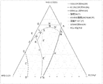
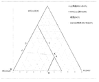
- FIG. 3 is a diagram showing points A to T and line segments connecting them in a ternary composition diagram in which the total sum of HFO-1132 (E), HFO-1123 and R1234yf is 100% by mass.
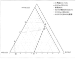
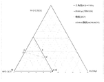
- the sum of HFO-1132 (E), HFO-1123 and R1234yf is (100 ⁇ a) mass%, points A to C, D ′, G, I, J and K ′ and their respective It is the figure which showed the line segment to connect.
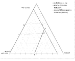
- the three-component composition diagram in which the sum of HFO-1132 (E), R32 and R1234yf is 100% by mass is a diagram showing points A to C, E, G, and I to W and line segments connecting them.
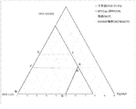
- FIG. 3 is a diagram showing points A to U and line segments connecting them in a ternary composition diagram in which the total sum of HFO-1132 (E), HFO-1123 and R32 is 100% by mass.
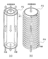
- It is a schematic diagram showing an example of a counterflow type heat exchanger. It is the schematic which shows the other example of a counterflow-type heat exchanger, (a) is a top view, (b) is a perspective view.
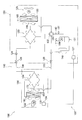
- FIG. 1 It is a schematic block diagram which shows the structure of the refrigerant circuit of the air conditioning apparatus as an example of the refrigerating-cycle apparatus which concerns on 3rd Embodiment of this indication. It is a schematic control block block diagram of the air conditioning apparatus of FIG.
- refrigerant includes at least a compound having a refrigerant number (ASHRAE number) defined by ISO 817 (International Organization for Standardization) and representing a type of refrigerant. Furthermore, even if the refrigerant number is not yet assigned, those having the same characteristics as the refrigerant are included.
- refrigerants are roughly classified into “fluorocarbon compounds” and “nonfluorocarbon compounds” in terms of the structure of the compounds.
- the "fluorocarbon compounds” include chlorofluorocarbons (CFCs), hydrochlorofluorocarbons (HCFCs) and hydrofluorocarbons (HFCs). Examples of the "non-fluorocarbon compound” include propane (R290), propylene (R1270), butane (R600), isobutane (R600a), carbon dioxide (R744), ammonia (R717) and the like.
- composition containing a refrigerant further includes (1) the refrigerant itself (including a mixture of refrigerants) and (2) other components, and at least a refrigerator by mixing with a refrigerator oil. At least a composition that can be used to obtain a working fluid, and (3) a working fluid for a refrigerator containing a refrigerator oil.
- the composition of (2) is referred to as “refrigerant composition” to distinguish it from the refrigerant itself (including a mixture of refrigerants).
- the thing of the working fluid for refrigerators for (3) is distinguished from a "refrigerant composition", and is described as a "refrigerant oil containing working fluid.”
- the term "alternate” is used in the context of "substituting" a first refrigerant with a second refrigerant, to operate using the first refrigerant as a first type
- the second refrigerant is used only by changing and adjusting the number of parts (at least one of refrigerator oil, gasket, packing, expansion valve, dryer and other parts) as needed. Mean that they can be operated under optimum conditions. That is, this type refers to operating the same device with "substituting" the refrigerant.
- this type of “alternate” “drop in alternative”, “nearly drop in” There may be nealy drop in 'and' retrofit '.
- the term "refrigerator” refers to any device that maintains a temperature lower than ambient air and maintains this low temperature by removing heat from objects or space.
- the refrigerator in order to transfer heat from the low temperature side to the high temperature side, the refrigerator refers to a conversion device that obtains energy from the outside, performs work and converts energy.
- the refrigerant being "WCF slight burn” means that the burning rate is 10 cm / s or less in the most flammable composition (WCF) according to the US ANSI / ASHRAE 34-2013 standard.
- that the refrigerant is "ASHRAE slight burn” means that the burning rate of WCF is 10 cm / s or less, and storage, transport, and use based on ANSI / ASHRAE 34-2013 using WCF.
- the most flammable fraction composition (Worst case of fractionation for flammability; WCFF) specified by conducting the leakage test has a burning rate of 10 cm / s or less and the flammability classification of US ANSI / ASHRAE 34-2013 is “ It means that it will be judged as "2L class”.
- RCL refrigerant concentration limit
- Temperature Glide refers to the absolute value of the difference between the onset temperature and the end temperature of the phase change process of the composition comprising the refrigerant of the present disclosure in the heat exchanger of the refrigerant system.
- Refrigerant (2-1) Refrigerant Component Although the details will be described later, any one of the refrigerants A, B, C, D, and E can be used as the refrigerant.
- the refrigerant of the present disclosure can be preferably used as a working fluid in a refrigerator.
- compositions of the present disclosure are suitable for use as substitutes for HFC refrigerants such as R410A, R407C and R404A, and HCFC refrigerants such as R22.
- the refrigerant composition of the present disclosure contains at least the refrigerant of the present disclosure and can be used for the same application as the refrigerant of the present disclosure.
- the refrigerant composition of the present disclosure can be used to obtain a working fluid for a refrigerator by further mixing with at least a refrigerator oil.
- the refrigerant composition of the present disclosure further contains at least one other component in addition to the refrigerant of the present disclosure.
- the refrigerant composition of the present disclosure may optionally contain at least one of the following other components.
- the refrigerant compositions of the present disclosure are preferably substantially free of refrigeration oil.
- the refrigerant composition of the present disclosure preferably has a refrigerator oil content of 0 to 1% by mass, more preferably 0 to 0.1% by mass, based on the entire refrigerant composition.
- the refrigerant composition of the present disclosure may contain a trace amount of water.
- the water content of the refrigerant composition is preferably 0.1% by mass or less based on the entire refrigerant.
- the intramolecular double bond of the unsaturated fluorocarbon compound which may be contained in the refrigerant is stabilized, and oxidation of the unsaturated fluorocarbon compound is also less likely to occur.
- the stability of the refrigerant composition is improved.
- the tracer is added to the refrigerant composition of the present disclosure at a detectable concentration so that when the refrigerant composition of the present disclosure is diluted, contaminated, or any other change can be traced. .
- the refrigerant composition of the present disclosure may contain one type alone or two or more types as a tracer.
- the tracer is not particularly limited, and can be appropriately selected from generally used tracers.
- a compound that can not be an impurity that is inevitably mixed in the refrigerant of the present disclosure is selected as a tracer.
- tracers examples include hydrofluorocarbons, hydrochlorofluorocarbons, chlorofluorocarbons, hydrochlorocarbons, fluorocarbons, deuterated hydrocarbons, deuterated hydrofluorocarbons, perfluorocarbons, fluoroethers, fluoroethers, brominated compounds, iodinated compounds, alcohols, Aldehydes, ketones, nitrous oxide (N2O) and the like can be mentioned.
- hydrofluorocarbons As a tracer, hydrofluorocarbons, hydrochlorofluorocarbons, chlorofluorocarbons, hydrochlorocarbons, fluorocarbons and fluoroethers are particularly preferred.
- the following compounds are preferable.
- FC-14 Tetrafluoromethane, CF 4 ) HCC-40 (chloromethane, CH 3 Cl) HFC-23 (trifluoromethane, CHF 3 ) HFC-41 (fluoromethane, CH 3 Cl) HFC-125 (pentafluoroethane, CF 3 CHF 2 ) HFC-134a (1,1,1,2-tetrafluoroethane, CF 3 CH 2 F) HFC-134 (1,1,2,2-tetrafluoroethane, CHF 2 CHF 2 ) HFC-143a (1,1,1-trifluoroethane, CF 3 CH 3 ) HFC-143 (1,1,2-trifluoroethane, CHF 2 CH 2 F) HFC-152a (1,1-difluoroethane, CHF 2 CH 3 ) HFC-152 (1,2-difluoroethane, CH 2 FCH 2 F) HFC-161 (Fluoroethane, CH 3 CH 2 F
- the tracer compound is present in the refrigerant composition at a total concentration of about 30 ppm to about 500 ppm, and most preferably, the tracer compound is present in the refrigerant composition at a total concentration of about 50 ppm to about 300 ppm.
- the refrigerant composition of the present disclosure may contain one kind alone or two or more kinds as an ultraviolet fluorescent dye.
- the ultraviolet fluorescent dye is not particularly limited, and can be appropriately selected from ultraviolet fluorescent dyes generally used.
- UV fluorescent dyes include, for example, naphthalimide, coumarin, anthracene, phenanthrene, xanthene, thioxanthene, naphthoxanthene and fluorescein, and derivatives thereof.
- the ultraviolet fluorescent dye either or both of naphthalimide and coumarin are particularly preferable.
- the refrigerant composition of the present disclosure may contain one kind alone, or two or more kinds as a stabilizer.
- the stabilizer is not particularly limited, and can be appropriately selected from generally used stabilizers.
- a stabilizer As a stabilizer, a nitro compound, ethers, amines etc. are mentioned, for example.
- nitro compound examples include aliphatic nitro compounds such as nitromethane and nitroethane, and aromatic nitro compounds such as nitrobenzene and nitrostyrene.
- ethers examples include 1,4-dioxane and the like.
- amines examples include 2,2,3,3,3-pentafluoropropylamine, diphenylamine and the like.
- the content ratio of the stabilizer is not particularly limited, and usually 0.01 to 5% by mass is preferable, and 0.05 to 2% by mass is more preferable with respect to the whole refrigerant.
- the refrigerant composition of the present disclosure may contain one kind alone, or may contain two or more kinds.
- the polymerization inhibitor is not particularly limited, and can be appropriately selected from commonly used polymerization inhibitors.
- polymerization inhibitor examples include 4-methoxy-1-naphthol, hydroquinone, hydroquinone methyl ether, dimethyl-t-butylphenol, 2,6-di-tert-butyl-p-cresol, benzotriazole and the like.
- the content ratio of the polymerization inhibitor is not particularly limited, and is usually preferably 0.01 to 5% by mass, and more preferably 0.05 to 2% by mass, with respect to the entire refrigerant.
- the refrigerator oil-containing working fluid of the present disclosure at least includes the refrigerant or the refrigerant composition of the present disclosure and a refrigerator oil, and is used as a working fluid in a refrigerator.
- the refrigerator oil-containing working fluid of the present disclosure is obtained by mixing the refrigerator oil used in the compressor of the refrigerator and the refrigerant or the refrigerant composition with each other.
- the refrigeration oil-containing working fluid generally contains 10 to 50% by mass of refrigeration oil.
- the refrigerator oil is not particularly limited, and can be appropriately selected from commonly used refrigerator oils. At that time, if necessary, a refrigerator oil more excellent in the miscibility with the mixture, the effect of improving the stability of the mixture, and the like can be appropriately selected.
- a base oil of refrigeration oil for example, at least one selected from the group consisting of polyalkylene glycol (PAG), polyol ester (POE) and polyvinyl ether (PVE) is preferable.
- PAG polyalkylene glycol
- POE polyol ester
- PVE polyvinyl ether
- the refrigerator oil may further contain an additive in addition to the base oil.
- the additive may be at least one selected from the group consisting of an antioxidant, an extreme pressure agent, an acid scavenger, an oxygen scavenger, a copper deactivator, a rust inhibitor, an oil agent and an antifoamer. .
- the refrigerator oil one having a kinematic viscosity at 40 ° C. of 5 to 400 cSt is preferable in terms of lubrication.
- the refrigerator oil-containing working fluid of the present disclosure may further contain at least one additive, as needed.
- the additive include the following compatibilizers and the like.
- the refrigeration oil-containing working fluid of the present disclosure may contain one kind alone or two or more kinds as a compatibilizing agent.
- the compatibilizer is not particularly limited, and can be appropriately selected from commonly used compatibilizers.
- compatibilizer examples include polyoxyalkylene glycol ethers, amides, nitriles, ketones, chlorocarbons, esters, lactones, aryl ethers, fluoroethers and 1,1,1-trifluoroalkanes.
- polyoxyalkylene glycol ether is particularly preferred.
- the following descriptions of the refrigerant A, the refrigerant B, the refrigerant C, the refrigerant D, and the refrigerant E are independent of one another, and alphabets indicating points and line segments, numbers of examples, and numbers of comparative examples are all
- the refrigerant A, the refrigerant B, the refrigerant C, the refrigerant D, and the refrigerant E are independent of each other.
- the first embodiment of the refrigerant A and the first embodiment of the refrigerant B show different embodiments.
- Refrigerant A of the present disclosure includes trans-1,2-difluoroethylene (HFO-1132 (E)), trifluoroethylene (HFO-1123) and 2,3,3,3-tetrafluoro-1-propene (R1234yf). Is a mixed refrigerant containing
- the refrigerant A of the present disclosure has desirable characteristics as an R410A alternative refrigerant, having the same refrigeration capacity and coefficient of performance as the R410A, and the GWP is sufficiently small.
- the refrigerant A of the present disclosure may be a composition containing HFO-1132 (E) and R1234yf, and optionally HFO-1123, and may further satisfy the following requirements.
- This refrigerant also has desirable characteristics as an R410A alternative refrigerant, having the same refrigeration capacity and coefficient of performance as R410A, and having a sufficiently small GWP.
- the refrigerant A of the present disclosure is HFO-1132 (E), HFO-, where x, y and z are mass% based on the total of HFO-1132 (E), HFO-1123 and R1234yf, respectively.
- the refrigerant A of the present disclosure is HFO-1132 (E), HFO-, where x, y and z are mass% based on the total of HFO-1132 (E), HFO-1123 and R1234yf, respectively.
- coordinates (x, y, z) are Point G (72.0, 28.0, 0.0), Point I (72.0, 0.0, 28.0), Point A (68.6, 0.0, 31.4), Point A '(30.6, 30.0, 39.4), Point B (0.0, 58.7, 41.3), Point D (0.0, 80.4, 19.6), Point C '(19.5, 70.5, 10.0) and point C (32.9, 67.1, 0.0)
- the line segment AA ′ is The line segment AA ′ is The
- the refrigerant of the present disclosure not only has a refrigeration capacity ratio of 85% or more based on R410A and a COP ratio of 92.5% or more based on R410A when the above requirements are satisfied, and further, it is further specified by ASHRAE. It shows WCF slight flammability (burn rate of WCF composition is 10 cm / s or less).
- the refrigerant A of the present disclosure is HFO-1132 (E), HFO-1123, where x, y and z are mass% of HFO-1132 (E) HFO-1123 and R1234yf based on the total of these.
- the coordinates (x, y, z) are Point J (47.1, 52.9, 0.0), Point P (55.8, 42.0, 2.2), Point N (68.6, 16.3, 15.1), Point K (61.3, 5.4, 33.3), Point A '(30.6, 30.0, 39.4), Point B (0.0, 58.7, 41.3), Point D (0.0, 80.4, 19.6), Point C '(19.5, 70.5, 10.0) and point C (32.9, 67.1, 0.0)
- the refrigerant of the present disclosure not only has a refrigeration capacity ratio of 85% or more based on R410A and a COP ratio of 92.5% or more based on R410A when the above requirements are satisfied, and further, it is further specified by ASHRAE. It shows slight flammability (2 L class (burning rate of WCF composition and WCFF composition is 10 cm / s or less)).
- the refrigerant A of the present disclosure is HFO-1132 (E), HFO-, where x, y and z are mass% based on the total of HFO-1132 (E), HFO-1123 and R1234yf, respectively.
- coordinates (x, y, z) are Point J (47.1, 52.9, 0.0), Point P (55.8, 42.0, 2.2), Point L (63.1, 31.9, 5.0), Point M (60.3, 6.2, 33.5), Point A '(30.6, 30.0, 39.4), Point B (0.0, 58.7, 41.3), Point D (0.0, 80.4, 19.6), Point C '(19.5, 70.5, 10.0) and point C (32.9, 67.1, 0.0)
- the refrigerant of the present disclosure has a refrigeration capacity ratio of 85% or more based on R410A and a COP ratio of 92.5% or more based on R410A when the above requirements are satisfied, and further, the RCL is 40 g / m 3 or more.
- the refrigerant A of the present disclosure is HFO-1132 (E), HFO-, where x, y and z are mass% based on the total of HFO-1132 (E), HFO-1123 and R1234yf, respectively.
- coordinates (x, y, z) are Point P (55.8, 42.0, 2.2), Point L (63.1, 31.9, 5.0), Point M (60.3, 6.2, 33.5), Point A '(30.6, 30.0, 39.4), Point B (0.0, 58.7, 41.3), Point F (0.0, 61.8, 38.2) and point T (35.8, 44.9, 19.3)
- the line segment PL is Coordinates (x, -0.1135x 2 + 12.112x- 280.43
- the refrigerant of the present disclosure has a refrigeration capacity ratio of 85% or more based on R410A and a COP ratio based on R410A of 95% or more when the above requirements are satisfied, and further, the RCL is 40 g / l. m 3 or more.
- the refrigerant A of the present disclosure is HFO-1132 (E), HFO-, where x, y and z are mass% based on the total of HFO-1132 (E), HFO-1123 and R1234yf, respectively.
- coordinates (x, y, z) are Point P (55.8, 42.0, 2.2), Point L (63.1, 31.9, 5.0), Point Q (62.8, 29.6, 7.6) and Point R (49.8, 42.3, 7.9)
- coordinates (x, y, z) are Point P (55.8, 42.0, 2.2), Point L (63.1, 31.9, 5.0), Point Q (62.8, 29.6, 7.6) and Point R (49.8, 42.3, 7.9)
- the line segment PL is Coordinates (x, -0.1135x 2 + 12.112x- 280.43, 0.1135x 2 -13.112x + 380.43)
- Represented by The line segment RP is The coordinates (x, 0.0067x 2 -0.7607x
- the refrigerant of the present disclosure has a COP ratio of 95% or more based on R410A when the above requirements are satisfied, and not only an RCL of 40 g / m 3 or more but also a condensation temperature glide of 1 ° C. or less .
- the refrigerant A of the present disclosure is HFO-1132 (E), HFO-, where x, y and z are mass% based on the total of HFO-1132 (E), HFO-1123 and R1234yf, respectively.
- coordinates (x, y, z) are Point S (62.6, 28.3, 9.1), Point M (60.3, 6.2, 33.5), Point A '(30.6, 30.0, 39.4), Point B (0.0, 58.7, 41.3), Point F (0.0, 61.8, 38.2) and point T (35.8, 44.9, 19.3)
- the refrigerant of the present disclosure has a refrigeration capacity ratio of 85% or more based on R410A, a COP ratio based on R410A of 95% or more, and RCL of 40 g / m 3 or more when the above requirements are satisfied. Not only that, the discharge pressure ratio based on R410A is 105% or less.
- the refrigerant A of the present disclosure is HFO-1132 (E), HFO-, where x, y and z are mass% based on the total of HFO-1132 (E), HFO-1123 and R1234yf, respectively.
- coordinates (x, y, z) are Point d (87.6, 0.0, 12.4), Point g (18.2, 55.1, 26.7), Point h (56.7, 43.3, 0.0) and point O (100.0, 0.0, 0.0)
- the line segment dg is Coordinates (0.0047y 2 -1.5177y + 87.598, y, -0.0047y 2 + 0.5177y + 12.402) Represented by The
- the refrigerant A of the present disclosure is HFO-1132 (E), HFO-, where x, y and z are mass% based on the total of HFO-1132 (E), HFO-1123 and R1234yf, respectively.
- coordinates (x, y, z) are Point l (72.5, 10.2, 17.3), Point g (18.2, 55.1, 26.7), Point h (56.7, 43.3, 0.0) and point i (72.5, 27.5, 0.0)
- the line segment lg is Coordinates (0.0047y 2 -1.5177y + 87.598, y, -0.0047y 2 + 0.5177y + 12.402) Represented by The line segment gh is Coordinates (0.0047y 2 -1.5177y + 87.598, y, -0.0047y 2 + 0.5177y + 12.402) Represented by The line segment gh is Coordinates (0.0047y 2 -1.5177y + 87.598, y, -0.0047y 2
- the refrigerant of the present disclosure has a refrigeration capacity ratio of 92.5% or more based on R410A and a COP ratio based on R410A of 92.5% or more when the above requirements are satisfied, and further, it is further specified by ASHRAE. Indicates slight flammability (2 L class).
- the refrigerant A of the present disclosure is HFO-1132 (E), HFO-, where x, y and z are mass% based on the total of HFO-1132 (E), HFO-1123 and R1234yf, respectively.
- coordinates (x, y, z) are Point d (87.6, 0.0, 12.4), Point e (31.1, 42.9, 26.0), Point f (65.5, 34.5, 0.0) and point O (100.0, 0.0, 0.0)
- the line segment de is Coordinates (0.0047y 2 -1.5177y + 87.598, y, -0.0047y 2 + 0.5177y + 12.402) Represented by The line segment ef is Coordinates (0.0047y 2 -1.5177y + 87.598, y, -0.0047y 2 + 0.5177y + 12.402) Represented by The line segment ef is Coordinates (0.0047y 2 -1.5177y + 87.598, y, -0.0047y 2 +
- the refrigerant A of the present disclosure is HFO-1132 (E), HFO-, where x, y and z are mass% based on the total of HFO-1132 (E), HFO-1123 and R1234yf, respectively.
- coordinates (x, y, z) are Point l (72.5, 10.2, 17.3), Point e (31.1, 42.9, 26.0), Point f (65.5, 34.5, 0.0) and point i (72.5, 27.5, 0.0)
- the line segment LE is Coordinates (0.0047y 2 -1.5177y + 87.598, y, -0.0047y 2 + 0.5177y + 12.402) Represented by The line segment ef
- the refrigerant of the present disclosure has a refrigeration capacity ratio of 93.5% or more based on R410A and a COP ratio based on R410A of 93.5% or more when the above requirements are satisfied, and further, it is further specified in ASHRAE standard. Indicates slight flammability (2 L class).
- the refrigerant A of the present disclosure is HFO-1132 (E), HFO-, where x, y and z are mass% based on the total of HFO-1132 (E), HFO-1123 and R1234yf, respectively.
- coordinates (x, y, z) are Point a (93.4, 0.0, 6.6), Point b (55.6, 26.6, 17.8), Point c (77.6, 22.4, 0.0) and point O (100.0, 0.0, 0.0)
- the line segment ab is Coordinates (0.0052y 2 -1.5588y + 93.385, y,-0.0052y 2 + 0.
- the refrigerant of the present disclosure has a refrigeration capacity ratio of 95% or more based on R410A and a COP ratio based on R410A of 95% or more when the above requirements are satisfied.
- the refrigerant A of the present disclosure is HFO-1132 (E), HFO-, where x, y and z are mass% based on the total of HFO-1132 (E), HFO-1123 and R1234yf, respectively.
- coordinates (x, y, z) are Point k (72.5, 14.1, 13.4), Point b (55.6, 26.6, 17.8) and point j (72.5, 23.2, 4.3)
- coordinates (x, y, z) are Point k (72.5, 14.1, 13.4), Point b (55.6, 26.6, 17.8) and point j (72.5, 23.2, 4.3)
- coordinates (x, y, z) are Point k (72.5, 14.1, 13.4), Point b (55.6, 26.6, 17.8) and point j (72.5, 23.2, 4.3)
- Within the range of the figure bounded by the line segments kb, bj and jk connecting the three points of The line segment kb is Coordinates (0.0052y 2
- the line segment bj is Coordinates (-0.0032z 2 -1.1791z + 77.593, 0.0032z 2 + 0.1791z + 22.407, z) It is preferable that the line segment jk is a straight line.
- the refrigerant of the present disclosure not only has a refrigeration capacity ratio of 95% or more based on R410A and a COP ratio based on R410A of 95% or more when the above requirements are satisfied, and further, it is further specified by ASHRAE. Indicates slight flammability (2 L class).
- the refrigerant A of the present disclosure may further contain other additional refrigerants in addition to HFO-1132 (E), HFO-1123 and R1234yf, as long as the above-described properties and effects are not impaired.
- the refrigerant of the present disclosure preferably contains 99.5% by mass or more, more preferably 99.75% by mass or more, of the total of HFO-1132 (E), HFO-1123 and R1234yf with respect to the entire refrigerant. It is more preferable to contain 99.9 mass% or more.
- the refrigerant A of the present disclosure may contain 99.5 mass% or more, 99.75 mass% or more, of the total of HFO-1132 (E), HFO-1123 and R1234yf with respect to the entire refrigerant. And may further contain 99.9% by mass or more.
- the additional refrigerant is not particularly limited and can be widely selected.
- the mixed refrigerant may contain one kind alone as an additional refrigerant, or may contain two or more kinds.
- Example of refrigerant A Below, the Example of the refrigerant
- the GWP of a composition containing a mixture of R1234yf and R410A was evaluated based on the value of the Intergovernmental Panel on Climate Change (IPCC) Fourth Report.
- the refrigeration capacity of a composition containing a mixture of R410A and HFO-1132 (E), HFO-1123, R1234yf is determined using the National Institute of Science and Technology (NIST) Reference Fluid Thermodynamic and Transport Properties Database (Refprop 9.0). It calculated
- HFO-1132 (E), HFO-1123 and HFO-1123 and HFO-1123 and HFO-1123 and HFO-1123 and H1234b, respectively, are represented by x, y and z, respectively.
- coordinates (x, y, z) are Point A (68.6, 0.0, 31.4), Point A '(30.6, 30.0, 39.4), Point B (0.0, 58.7, 41.3), Point D (0.0, 80.4, 19.6), Point C '(19.5, 70.5, 10.0), Point C (32.9, 67.1, 0.0) and point O (100.0, 0.0, 0.0)
- the line segment AA ′ is The coordinates (x, 0.0016x 2 -0.9473x + 57.497 ,
- the point on the line segment AA ′ was determined by finding an approximate curve connecting three points of the point A, the example 1, and the point A ′ by the least square method.
- the point on the line segment A′B was determined by finding an approximate curve connecting the three points of the point A ′, the example 3 and the point B by the least square method.
- the point on the line segment DC ′ was determined by finding an approximate curve connecting the three points of the point D, the example 6, and the point C ′ by the least square method.
- the point on line segment C'C was determined by calculating
- the coordinates (x, y, z) are Point A (68.6, 0.0, 31.4), Point A '(30.6, 30.0, 39.4), Point B (0.0, 58.7, 41.3), Point F (0.0, 61.8, 38.2), Point T (35.8, 44.9, 19.3), Point E (58.0, 42.0, 0.0) and point O (100.0, 0.0, 0.0)
- the line segment AA ′ is The coordinates (x, 0.0016x 2 -0.9473x + 57.497 , -0.0016x 2 -0.0527x + 42.503) Represented by The line segment A'B is Coordinates (x, 0.0029x 2 -1.0268x + 58.7 , -0.0029x 2 + 0.0268x + 41.3) Represented by The line segment FT is
- the points on the line segment FT were determined by finding an approximate curve connecting the three points T, E 'and F by the least squares method.
- the points on the line segment TE were determined by finding an approximate curve connecting the three points E, R and T by the least square method.
- R1234yf contributes to the reduction of flammability and the suppression of deterioration such as polymerization, and it is preferable to include this.
- the burning rate was measured according to the ANSI / ASHRA 34-2013 standard, with the mixed composition as the WCF concentration.
- the one with a burning rate of 10 cm / s or less is considered as "2 L class (slight flammability)".
- the burning rate test was done as follows using the apparatus shown in FIG. In FIG. 1, 901 indicates a sample cell, 902 indicates a high-speed camera, 903 indicates a xenon lamp, 904 indicates a collimating lens, 905 indicates a collimating lens, and 906 indicates a ring filter.
- the mixed refrigerant used was 99.5% or more pure and degassed by repeated cycles of freezing, pumping and thawing until no traces of air were visible on the vacuum gauge.
- the burning rate was measured by the closure method. The initial temperature was ambient temperature. Ignition was performed by creating an electrical spark between the electrodes at the center of the sample cell.
- the duration of the discharge was 1.0 to 9.9 ms, and the ignition energy was typically about 0.1 to 1.0 J.
- the spread of the flame was visualized using Schlieren photographs.
- a cylindrical container (inner diameter: 155 mm, length: 198 mm) equipped with two acrylic windows for transmitting light was used as a sample cell, and a xenon lamp was used as a light source.
- Schlieren images of flames were recorded with a high speed digital video camera at a framing rate of 600 fps and stored on a PC.
- the WCFF concentration was determined by performing leakage simulation according to NIST Standard Reference Data Base Refleak Version 4.0 with the WCF concentration as the initial concentration.
- the line segment PN is Coordinates (x, -0.1135x 2 + 12.112x- 280.43, 0.1135x 2 -13.112x + 380.43) Represented by
- the line segment NK is Coordinates (x, 0.2421x 2 -29.955x + 931.91, -0.2421x 2 + 28.955x-831.91) It is represented by.
- the point on the line segment PN was determined by finding an approximate curve connecting the three points P, L, and N by the least squares method.
- the point on the line segment NK was determined by finding an approximate curve connecting the three points of the point N, the point N 'and the point K by the least square method.
- the refrigerant B of the present disclosure is 99.5 mass% or more of the total of trans-1,2-difluoroethylene (HFO-1132 (E)) and trifluoroethylene (HFO-1123) with respect to the whole of the refrigerant, and the refrigerant is HFO- Or a mixed refrigerant containing 62.0% by mass to 72.0% by mass or 45.1% by mass to 47.1% by mass of 1132 (E) based on the whole of the refrigerant, or
- the total of HFO-1132 (E) and HFO-1123 is 99.5 mass% or more with respect to the whole of the refrigerant, and the refrigerant contains 40.1 mass% of HFO-1132 (E) with respect to the whole of the refrigerant It is a mixed refrigerant containing ⁇ 47.1% by mass.
- the refrigerant B of the present disclosure has (1) a coefficient of performance equivalent to R410A, (2) refrigeration capacity equivalent to R410A, (3) sufficiently small GWP, and (4) ASHRAE standard. It has desirable characteristics as a R410A alternative refrigerant, that is, it is slightly flammable (2 L class).
- the refrigerant B of the present disclosure is a WCF slight-combustible if it is a mixed refrigerant containing 72.0% by mass or less of HFO-1132 (E).
- the refrigerant B of the present disclosure is a composition containing HFO-1132 (E) at 47.1% or less, and is a “2 L class” which is a slightly flammable refrigerant according to ASHRAE standards with WCF slight combustion and WCFF slight combustion, and handling is easier It becomes.
- the refrigerant B of the present disclosure contains 62.0% by mass or more of HFO-1132 (E)
- the coefficient of performance coefficient based on R410A is more excellent at 95% or more, and HFO-1132 (E) and / or Or, the polymerization reaction of HFO-1123 is further suppressed, and the stability becomes more excellent.
- the refrigerant B of the present disclosure contains 45.1% by mass or more of HFO-1132 (E)
- the coefficient of performance coefficient based on R410A is more excellent at 93% or more, and HFO-1132 (E) and / or Or, the polymerization reaction of HFO-1123 is further suppressed, and the stability becomes more excellent.
- the refrigerant B of the present disclosure may further contain other additional refrigerants in addition to HFO-1132 (E) and HFO-1123 as long as the above-described properties and effects are not impaired.
- the refrigerant B of the present disclosure more preferably contains the total of HFO-1132 (E) and HFO-1123 at 99.75 mass% or more, further preferably 99.9 mass% or more with respect to the entire refrigerant.
- the additional refrigerant is not particularly limited and can be widely selected.
- the mixed refrigerant may contain one kind alone as an additional refrigerant, or may contain two or more kinds.
- Example of refrigerant B Below, the Example of the refrigerant
- a mixed refrigerant was prepared by mixing HFO-1132 (E) and HFO-1123 in mass% (mass%) shown in Table 37 and Table 38, respectively, based on the total of them.
- IPCC Intergovernmental Panel on Climate Change
- the refrigeration capacity of a composition containing a mixture of R410A and HFO-1132 (E) and HFO-1123 is as follows using the National Institute of Science and Technology (NIST) Reference Fluid Thermodynamic and Transport Properties Database (Refprop 9.0) It calculated
- the composition of each mixture is WCF, and NIST Standard Reference Data Base Version under the condition of Equipment, Storage, Shipping, Leak, and Recharge according to ASHRAE 34-2013 standard. A leak simulation was performed according to 4.0, and the most flammable fraction was WCFF.
- GWP, COP and refrigeration capacity calculated based on these results are shown in Tables 1 and 2.
- the ratio COP and the specific refrigeration capacity are shown relative to R410A.
- the coefficient of performance (COP) was determined by the following equation.
- COP (refrigeration capacity or heating capacity) / power consumption
- the flammability was measured the burning rate according to the ANSI / ASHRAE 34-2013 standard. If the burning rate is 10 cm / s or less for both WCF and WCFF, it is considered as "2 L class (slight flammability)".
- the burning rate test was conducted as follows using the apparatus shown in FIG. First, the mixed refrigerant used was 99.5% or more pure and degassed by repeated cycles of freezing, pumping and thawing until no traces of air were visible on the vacuum gauge. The burning rate was measured by the closure method. The initial temperature was ambient temperature. Ignition was performed by creating an electrical spark between the electrodes at the center of the sample cell. The duration of the discharge was 1.0 to 9.9 ms, and the ignition energy was typically about 0.1 to 1.0 J. The spread of the flame was visualized using Schlieren photographs.
- a cylindrical container (inner diameter: 155 mm, length: 198 mm) equipped with two acrylic windows for transmitting light was used as a sample cell, and a xenon lamp was used as a light source.
- Schlieren images of flames were recorded with a high speed digital video camera at a framing rate of 600 fps and stored on a PC.
- Refrigerant C of the present disclosure includes trans-1,2-difluoroethylene (HFO-1132 (E)), trifluoroethylene (HFO-1123) and 2,3,3,3-tetrafluoro-1-propene (R1234yf). And difluoromethane (R32), which further satisfy the following requirements.
- the refrigerant C of the present disclosure has desirable characteristics as an R410A alternative refrigerant, having a refrigeration capacity and a coefficient of performance equivalent to that of R410A, and having a sufficiently small GWP.
- the refrigerant C of the present disclosure is HFO-1132, where the mass% of HFO-1132 (E), HFO-1123 and R1234yf, and R32 based on the total of these is x, y and z, and a, respectively.
- Point A (0.0107a 2 -1.9142a + 68.305, 0.0, -0.0107a 2 + 0.9142a + 31.695)
- Point B (0.0, 0.009a 2 -1.6045a + 59.318, -0.009a 2 + 0.6045a + 40.682)
- the point W (0.0, 100.0-a, 0.0)
- GI, IA, AB, BW and WG respectively connecting the five points of the above, or on the straight lines GI and AB (however, points G, I, except)
- Point G (0.0111a 2 -1.3152a + 68.986,-0.0111a 2 + 0.3152a + 31.014, 0.0)
- Point I (0.0111a 2 -1.3152a + 68.986, 0.0,-0.0111a 2 + 0.3152a + 31.014)
- Point A (0.0103a 2 -1.9225a + 68.793, 0.0, -0.0103a
- the refrigerant C of the present disclosure is HFO-1132 (E), HFO- when the mass% of HFO-1132 (E), HFO-1123 and R1234yf based on the total of these is respectively x, y and z.
- coordinates (x, y, z) are When 0 ⁇ a ⁇ 11.1
- Point J (0.0049a 2 -0.9645a + 47.1, -0.0049a 2 -0.0355a + 52.9, 0.0)
- Point B (0.0, 0.0144a 2 -1.6377a + 58.7,-0.0144a 2 + 0.6377a + 41.3)
- Point D (0.0, 0.0224a 2 + 0.968a
- the refrigerant of the present disclosure not only achieves a refrigeration capacity ratio of 85% or more based on R410A and a COP ratio of 92.5% or more based on R410A when the above requirements are satisfied, and further, WCF slight combustion and WCFF slight burn and ASHRAE standards indicate "2L class", a slightly burnt refrigerant.
- the refrigerant C of the present disclosure further includes R32 in addition to HFO-1132 (E), HFO-1123 and R1234yf, the sum of HFO-1132 (E), HFO-1123 and R1234yf, and R32 is used as a standard.
- R410A is a point It is an intersection point of an approximate straight line connecting points where the COP ratio is 95% and a straight line ab.
- the refrigerant of the present disclosure has a refrigeration capacity ratio of 95% or more based on R410A and a COP ratio based on R410A of 95% or more when the above requirements are satisfied.
- the refrigerant C of the present disclosure may further contain other additional refrigerant in addition to HFO-1132 (E), HFO-1123 and R1234yf, and R32, as long as the above-described properties and effects are not impaired. Good.
- the refrigerant of the present disclosure preferably contains 99.5% by mass or more, more preferably 99.75% by mass or more, of the total of HFO-1132 (E), HFO-1123 and R1234yf, and R32 with respect to the entire refrigerant. Preferably, 99.9% by mass or more is included.
- the refrigerant C of the present disclosure may contain 99.5% by mass or more and 99.75% by mass or more of the total of HFO-1132 (E), HFO-1123 and R1234yf, and R32 with respect to the entire refrigerant. And may contain 99.9% by mass or more.
- the additional refrigerant is not particularly limited and can be widely selected.
- the mixed refrigerant may contain one kind alone as an additional refrigerant, or may contain two or more kinds.
- Example of refrigerant C Below, the Example of the refrigerant
- a mixed refrigerant was prepared by mixing HFO-1132 (E), HFO-1123 and R1234yf, and R32 in the mass% shown in Tables 39 to 96, respectively, based on the total of these.
- IPCC Intergovernmental Panel on Climate Change
- the refrigeration capacity of a composition containing a mixture of R410A and HFO-1132 (E) and HFO-1123 is as follows using the National Institute of Science and Technology (NIST) Reference Fluid Thermodynamic and Transport Properties Database (Refprop 9.0) It calculated
- the COP ratio and the refrigeration capacity ratio were determined with reference to R410.
- the calculation conditions were as follows.
- Evaporation temperature 5 ° C Condensing temperature: 45 ° C Superheat: 5K Degree of supercooling; 5K Compressor efficiency 70% These values are shown in Tables 39 to 96 together with the GWP for each mixed refrigerant. The ratio COP and the specific refrigeration capacity are shown relative to R410A.
- the coefficient of performance (COP) was determined by the following equation.
- HFO-1132 (E: HFO-1132 (E), HFO-1123 and R1234yf, and R32, based on the sum of these, mass% is x, y and z, and a, respectively).
- HFO-1123 and R1234yf the bottom line is a straight line connecting point (0.0, 100.0-a, 0.0) and point (0.0, 0.0, 100, 0-a) where the mass becomes (100-a) mass%
- the coordinates (x, y, z) are When 0 ⁇ a ⁇ 11.1 Point A (0.0134a 2 -1.9681a + 68.6, 0.0, -0.0134a 2 + 0.9681a + 31.4) and point B (0.0, 0.0144a 2 -1.6377a + 58.7, -0.0144a 2 + 0.6377a + 41.3) and A straight line AB connecting the When 11.1
- a point at which the actual refrigeration capacity ratio is 85% is a curve that extends to the 1234yf side connecting the point A and the point B shown in FIG. Therefore, when it is on the straight line AB or on the left side, the refrigeration capacity ratio based on R410A is 85% or more.
- the coordinates (x, y, z) are When 0 ⁇ a ⁇ 11.1 Point D '(0.0, 0.0224a 2 + 0.968a + 75.4, -0.0224a 2 -1.968a + 24.6) and point C (-0.2304a 2 -0.4062a + 32.9, 0.2304a 2 -0.5938a + 67.1, 0.0) And the straight line D′ C connecting the When 11.1 ⁇ a ⁇ 46.7 It can be seen that the COP ratio based on R410A is 92.5% or more when in all the regions.
- FIG. 3 it is the curve CD that the COP ratio is 92.5% or more, but in FIG. 3, when the R1234yf concentration is 5% by mass and 10% by mass, the COP ratio is 92.5% (26.6, 68.4, 5), (19.5, 70.5, 10), and an approximate straight line connecting three points C (32.9, 67.1, 0.0), and the intersection point D ′ (0, 0, 0) with the HFO-1132 (E) concentration of 0.0 mass% A straight line connecting 75.4, 24.6) and the point C is a line segment D'C. Also, in FIG. 4, D ′ (D) is similarly derived from an approximate curve connecting point C (18.4, 74.5, 0), point (13.9, 76.5, 2.5), and point (8.7, 79. Find 0, 83.4, 9.5), and let D'C be a straight line connecting point C.
- composition of each mixture is WCF, and NIST Standard Reference Data Base Version under the condition of Equipment, Storage, Shipping, Leak, and Recharge according to ASHRAE 34-2013 standard.
- a leak simulation was performed according to 4.0, and the most flammable fraction was WCFF.
- the flammability was measured according to the ANSI / ASHRAE 34-2013 standard. If the burning rate is 10 cm / s or less for both WCF and WCFF, it is considered as "2 L class (slight flammability)".
- the burning rate test was done as follows using the apparatus shown in FIG. First, the mixed refrigerant used was 99.5% or more pure and degassed by repeated cycles of freezing, pumping and thawing until no traces of air were visible on the vacuum gauge. The burning rate was measured by the closure method. The initial temperature was ambient temperature. Ignition was performed by creating an electrical spark between the electrodes at the center of the sample cell. The duration of the discharge was 1.0 to 9.9 ms, and the ignition energy was typically about 0.1 to 1.0 J. The spread of the flame was visualized using Schlieren photographs.
- a cylindrical container (inner diameter: 155 mm, length: 198 mm) equipped with two acrylic windows for transmitting light was used as a sample cell, and a xenon lamp was used as a light source.
- Schlieren images of flames were recorded with a high speed digital video camera at a framing rate of 600 fps and stored on a PC.
- the point of the actual WCFF slight combustion becomes a curve which spreads to the HFO-1132 (E) side connecting the point J and the point K '(on the straight line AB) shown in FIG. Therefore, when it is on the line of straight line JK 'or below, it becomes WCFF slight flame retardance.
- the R32 content ratio a (mass%) is 0 mass%, 7.1 mass%, 11.1 mass%, 14.5 mass%, 18.2 mass%, 21.9 mass%, 26.7 mass%, respectively.
- the compositions are shown for 29.3% by weight, 36.7% by weight, 44.1% by weight and 47.8% by weight.
- Point A is a point where the HFO-1123 content is 0% by mass and the refrigeration capacity ratio based on R410A is 85%. With respect to the point A, three points were obtained for each of the following five ranges by calculation, and their approximate expressions were obtained (Table 109).
- Point B is a point at which the HFO-1132 (E) content rate is 0% by mass and the refrigeration capacity ratio based on R410A is 85%.
- E HFO-1132
- the point D ' is a point at which the HFO-1132 (E) content rate is 0% by mass and the COP ratio based on R410A is 95.5%.
- the following three points were obtained by calculation and their approximate expressions were obtained (Table 111).
- Point C is a point where the R1234yf content rate is 0% by mass and the COP ratio based on R410A is 95.5%.
- point C the following three points were obtained by calculation, and their approximate expressions were obtained (Table 112).
- the refrigerant D of the present disclosure is a mixture containing trans-1,2-difluoroethylene (HFO-1132 (E)), difluoromethane (R32) and 2,3,3,3-tetrafluoro-1-propene (R1234yf). It is a refrigerant.
- the refrigerant D of the present disclosure has desirable characteristics as an R410A alternative refrigerant, having a cooling capacity equivalent to that of R410A, a sufficiently small GWP, and a slight flammability (2 L class) according to the ASHRAE standard.
- the refrigerant D of the present disclosure is HFO-1132 (E), R32 and R1234yf, where x, y and z are mass% of HFO-1132 (E), R32 and R1234yf, respectively, based on their total sum.
- the coordinates (x, y, z) are Point I (72.0, 0.0, 28.0), Point J (48.5, 18.3, 33.2), Point N (27.7, 18.2, 54.1) and point E (58.3, 0.0, 41.7)
- the line segment IJ is Coordinates (0.0236y 2 -1.7616y +72.0, y, -0.0236y 2 + 0.7616y +28.0) Represented by
- the line segment NE is Coordinates (0.012y 2 -1.9003y + 58.3, y, -0.012y 2 + 0.9003y + 41.7) It is preferable that the line segments JN and EI be straight lines.
- the refrigerant of the present disclosure has a refrigeration capacity
- the refrigerant D of the present disclosure is HFO-1132 (E), R32 and R1234yf, where x, y and z are mass% of HFO-1132 (E), R32 and R1234yf, respectively, based on their total sum.
- the coordinates (x, y, z) are Point M (52.6, 0.0, 47.4), Point M '(39.2, 5.0, 55.8), Point N (27.7, 18.2, 54.1), Point V (11.0, 18.1, 70.9) and Point G (39.6, 0.0, 60.4)
- the line segment MM ' is Coordinates (x, 0.132x 2 -3.34x + 52.6, -0.132x 2 + 2.34x + 47.4)
- the line segment M'N is Coordinates (x, 0.0313x 2 -1.4551x + 43.824, -0.0313x 2 + 0.4551x + 56.
- the line segment VG is Coordinates (0.0123y 2 -1.8033y + 39.6, y, -0.0123y 2 + 0.8033y + 60.4) It is preferable that the line segments NV and GM be straight.
- the refrigerant of the present disclosure has a refrigeration capacity ratio of 70% or more based on R410A, a GWP of 125 or less, and ASHRAE slight burn.
- the refrigerant D of the present disclosure is HFO-1132 (E), R32 and R1234yf, where x, y and z are mass% of HFO-1132 (E), R32 and R1234yf, respectively, based on their total sum.
- the coordinates (x, y, z) are Point O (22.6, 36.8, 40.6), Point N (27.7, 18.2, 54.1) and point U (3.9, 36.7, 59.4)
- the line segments ON, NU and UO respectively connecting the three points of The line segment ON is Coordinates (0.0072y 2 -0.6701y + 37.512, y , -0.0072y 2 -0.3299y + 62.488)
- the line segment NU is Coordinates (0.0083y 2 -1.7403y +56.635, y, -0.0083y 2 + 0.7403y +43.365)
- the line segment UO be a straight line.
- the refrigerant of the present disclosure has a refrigeration capacity ratio of 80% or more based on R410A, a GWP of 250 or less, and ASHRAE slight burn.
- the refrigerant D of the present disclosure is HFO-1132 (E), R32 and R1234yf, where x, y and z are mass% of HFO-1132 (E), R32 and R1234yf, respectively, based on their total sum.
- the coordinates (x, y, z) are Point Q (44.6, 23.0, 32.4), Point R (25.5, 36.8, 37.7), Point T (8.6, 51.6, 39.8), Point L (28.9, 51.7, 19.4) and Point K (35.6, 36.8, 27.6)
- Point Q 44.6, 23.0, 32.4
- Point R (25.5, 36.8, 37.7)
- Point T (8.6, 51.6, 39.8)
- Point L 28.9, 51.7, 19.4
- Point K (35.6, 36.8, 27.6)
- the line segments QR, RT, TL, LK and KQ connecting the five points of The line segment QR is Coordinates (0.0099 y 2 -1. 975 y + 84.
- the line segment RT is Coordinates (0.082y 2 -1.8683y + 83.126, y, -0.082y 2 + 0.8683y + 16.874)
- the line segment LK is Coordinates (0.0049y 2 -0.8842y + 61.488, y, -0.0049y 2 -0.1158y + 38.512)
- the line segment KQ is Coordinates (0.0095y 2 -1.2222y + 67.676, y, -0.0095y 2 + 0.2222y + 32.324) It is preferable that the line segment TL be a straight line.
- the refrigerant of the present disclosure has a refrigeration capacity ratio of 92.5% or more based on R410A, a GWP of 350 or less, and WCF slight combustion.
- the refrigerant D of the present disclosure is HFO-1132 (E), R32 and R1234yf, where x, y and z are mass% of HFO-1132 (E), R32 and R1234yf, respectively, based on their total sum.
- the coordinates (x, y, z) are Point P (20.5, 51.7, 27.8), Point S (21.9, 39.7, 38.4) and point T (8.6, 51.6, 39.8)
- the line segment PS is Coordinates (0.0064y 2 -0.7103y + 40.1, y, -0.0064y 2 -0.2897y + 59.9)
- the line segment ST is Coordinates (0.082y 2 -1.8683y + 83.126, y, -0.082y 2 + 0.8683y + 16.874)
- the line segment TP is a straight line.
- the refrigerant of the present disclosure has a refrigeration capacity ratio of 92.5% or more based on R410A, a GWP of 350 or less, and ASHRAE incombustible when the above requirements are satisfied.
- the refrigerant D of the present disclosure is HFO-1132 (E), R32 and R1234yf, where x, y and z are mass% of HFO-1132 (E), R32 and R1234yf, respectively, based on their total sum.
- the coordinates (x, y, z) are Point a (71.1, 0.0, 28.9), Point c (36.5, 18.2, 45.3), Point f (47.6, 18.3, 34.1) and point d (72.0, 0.0, 28.0)
- the line segment ac is Coordinates (0.0181y 2 -2.2288y + 71.096, y, -0.0181y 2 + 1.2288y +28.904)
- the line segment fd is Coordinates (0.02y 2 -1.7y + 72, y , -0.02y 2 + 0.7y + 28)
- the line segments cf and da are straight.
- the refrigerant of the present disclosure has a refrigeration capacity ratio of 85% or more based on R410A, a GWP of 125 or less, and a slight flame retardancy (2 L class) according to the ASHRAE standard.
- the refrigerant D of the present disclosure is HFO-1132 (E), R32 and R1234yf, where x, y and z are mass% of HFO-1132 (E), R32 and R1234yf, respectively, based on their total sum.
- the coordinates (x, y, z) are Point a (71.1, 0.0, 28.9), Point b (42.6, 14.5, 42.9), Point e (51.4, 14.6, 34.0) and point d (72.0, 0.0, 28.0)
- the line segment ab is Coordinates (0.0181y 2 -2.2288y + 71.096, y, -0.0181y 2 + 1.2288y +28.904)
- the line segment ed is Coordinates (0.02y 2 -1.7y + 72, y , -0.02y 2 + 0.7y + 28)
- the line segments be and da are straight lines.
- the refrigerant of the present disclosure has a refrigeration capacity ratio of 85% or more based on R410A, a GWP of 100 or less, and a slight flame retardancy (2 L class) according to the ASHRAE standard.
- the refrigerant D of the present disclosure is HFO-1132 (E), R32 and R1234yf, where x, y and z are mass% of HFO-1132 (E), R32 and R1234yf, respectively, based on their total sum.
- the coordinates (x, y, z) are Point g (77.5, 6.9, 15.6), Point iI (55.1, 18.3, 26.6) and point j (77.5.
- the refrigerant of the present disclosure has a refrigeration capacity ratio of 95% or more based on R410A, a GWP of 100 or less, and is resistant to changes such as polymerization or decomposition, and is excellent in stability. .
- the refrigerant D of the present disclosure is HFO-1132 (E), R32 and R1234yf, where x, y and z are mass% of HFO-1132 (E), R32 and R1234yf, respectively, based on their total sum.
- the coordinates (x, y, z) are Point g (77.5, 6.9, 15.6), Point h (61.8, 14.6, 23.6) and point k (77.5, 14.6, 7.9)
- the line segments gh, hk and kg connecting the three points of The line segment gh is Coordinates (0.02y 2 -2.4583y + 93.396, y , -0.02y 2 + 1.4583y + 6.604)
- the line segments hk and kg are straight.
- the refrigerant of the present disclosure has a refrigeration capacity ratio of 95% or more based on R410A, a GWP of 100 or less, and is resistant to changes such as polymerization or decomposition, and is excellent in stability. .
- the refrigerant D of the present disclosure may further contain other additional refrigerant in addition to HFO-1132 (E), R32 and R1234yf, as long as the above-mentioned properties and effects are not impaired.
- the refrigerant D of the present disclosure preferably contains 99.5% by mass or more, more preferably 99.75% by mass or more, of the total of HFO-1132 (E), R32 and R1234yf with respect to the entire refrigerant. It is more preferable to contain mass% or more.
- the additional refrigerant is not particularly limited and can be widely selected.
- the mixed refrigerant may contain one kind alone as an additional refrigerant, or may contain two or more kinds.
- Example of refrigerant D Below, the Example of the refrigerant
- each mixed refrigerant of HFO-1132 (E), R32 and R1234yf is WCF, and according to the ASHRAE 34-2013 standard, equipment (Storage), Storage (Storage), Transportation (Shipping), Leakage (Leak) and Recharge (Recharge) Leakage simulation was performed according to NIST Standard Reference Data Base Refleak Version 4.0 under the following conditions, and the most flammable fraction was WCFF.
- the burning rate test was done as follows using the apparatus shown in FIG. First, the mixed refrigerant used was 99.5% or more pure and degassed by repeated cycles of freezing, pumping and thawing until no traces of air were visible on the vacuum gauge. The burning rate was measured by the closure method. The initial temperature was ambient temperature. Ignition was performed by creating an electrical spark between the electrodes at the center of the sample cell. The duration of the discharge was 1.0 to 9.9 ms, and the ignition energy was typically about 0.1 to 1.0 J. The spread of the flame was visualized using Schlieren photographs.
- a cylindrical container (inner diameter: 155 mm, length: 198 mm) equipped with two acrylic windows for transmitting light was used as a sample cell, and a xenon lamp was used as a light source.
- Schlieren images of flames were recorded with a high speed digital video camera at a framing rate of 600 fps and stored on a PC. The results are shown in Tables 113-115.
- the coordinates (x, y, z) indicate line segments connecting point M, point M ′, point W, point J, point N, and point P, respectively.
- a mixed refrigerant was prepared by mixing HFO-1132 (E), R32 and R1234yf in the% by mass shown in Tables 116 to 144, respectively, based on their total sum.
- the coefficient of performance (coefficient of performance (COP)) ratio based on R410 and the refrigeration capacity ratio were determined. The calculation conditions were as follows.
- the refrigerant D of the present disclosure is HFO-1132 (E), where x, y and z represent mass% of HFO-1132 (E), R32 and R1234yf based on their total sum, respectively.
- the coordinates (x, y, z) are Point I (72.0, 0.0, 28.0), Point J (48.5, 18.3, 33.2), Point N (27.7, 18.2, 54.1) and point E (58.3, 0.0, 41.7)
- the line segment IJ is Coordinates (0.0236y 2 -1.7616y +72.0, y, -0.0236y 2 + 0.7616y +28.0) Represented by The line segment NE is Coordinates (0.0236y 2 -1.7616y +72.0, y, -0.0236y 2 + 0.7616y +28.0) Represented by The line segment NE is Coordinates (0.0236y 2 -1.7616y +72.0, y, -0.0236y 2 + 0.76
- the refrigerant D of the present disclosure is HFO-1132 (E), R32 and R32 when the mass% of HFO-1132 (E), R32 and R1234yf based on the total of these is respectively x, y and z.
- coordinates (x, y, z) are Point M (52.6, 0.0, 47.4), Point M '(39.2, 5.0, 55.8), Point N (27.7, 18.2, 54.1), Point V (11.0, 18.1, 70.9) and Point G (39.6, 0.0, 60.4)
- the line segment VG is Coordinates (0.0123y 2 -1.8033y + 39.6, y, -0.0123y 2 + 0.8033y + 60.4) It can be seen that when the line segments NV and GM are straight, the refrigeration capacity ratio based on R410A is 70% or more, the GWP is 125 or less, and ASHRAE slight burn is achieved.
- the refrigerant D of the present disclosure is HFO-1132 (E), R32 and R32, where the mass% of HFO-1132 (E), R32 and R1234yf based on the total of these is respectively x, y and z.
- the refrigerant D of the present disclosure is HFO-1132 (E), R32 and R32 when the mass% of HFO-1132 (E), R32 and R1234yf based on the total of these is respectively x, y and z.
- coordinates (x, y, z) are Point Q (44.6, 23.0, 32.4), Point R (25.5, 36.8, 37.7), Point T (8.6, 51.6, 39.8), Point L (28.9, 51.7, 19.4) and Point K (35.6, 36.8, 27.6)
- coordinates (x, y, z) are Point Q (44.6, 23.0, 32.4), Point R (25.5, 36.8, 37.7), Point T (8.6, 51.6, 39.8), Point L (28.9, 51.7, 19.4) and Point K (35.6, 36.8, 27.6)
- the line segments QR, RT, TL, LK and KQ connecting the five points of The line segment QR is Coordinates (0.0099 y 2 -1.
- the line segment RT is Coordinates (0.082y 2 -1.8683y + 83.126, y, -0.082y 2 + 0.8683y + 16.874)
- the line segment LK is Coordinates (0.0049y 2 -0.8842y + 61.488, y, -0.0049y 2 -0.1158y + 38.512)
- the line segment KQ is Coordinates (0.0095y 2 -1.2222y + 67.676, y, -0.0095y 2 + 0.2222y + 32.324)
- the refrigerating capacity ratio based on R410A is 92.5% or more
- the GWP is 350 or less
- the WCF is slightly combustible.
- the refrigerant D of the present disclosure is HFO-1132 (E), R32 and R32, where the mass% of HFO-1132 (E), R32 and R1234yf based on the total of these is respectively x, y and z.
- the refrigerant E of the present disclosure is a mixed refrigerant containing trans-1,2-difluoroethylene (HFO-1132 (E)), trifluoroethylene (HFO-1123) and difluoromethane (R32).
- the refrigerant E of the present disclosure has desirable characteristics as an R410A alternative refrigerant, having a coefficient of performance equivalent to that of R410A, and a sufficiently small GWP.
- the refrigerant E of the present disclosure is HFO-1132 (E), HFO-, where the mass% of HFO-1132 (E), HFO-1123 and R32 based on the total of these is respectively x, y and z.
- coordinates (x, y, z) are Point I (72.0, 28, 0, 0.0) Point K (48.4, 33.2, 18.4) Point B '(0.0, 81.6, 18.4) Point H (0.0, 84.2, 15.8) Point R (23.1, 67.4, 9.5) and Point G (38.5, 61.5, 0.0)
- the line segment IK is Coordinates (0.025z 2 -1.7429z + 72.00, -0.025z 2 + 0.7429z + 28.0, z) Represented by The line segment HR is Coordinates (-
- the refrigerant E of the present disclosure is HFO-1132 (E), HFO-, where the mass% of HFO-1132 (E), HFO-1123 and R32 based on the total of these is respectively x, y and z.
- coordinates (x, y, z) are Point I (72.0, 28, 0, 0.0) Point J (57.7, 32.8, 9.5) Point R (23.1, 67.4, 9.5) and Point G (38.5, 61.5, 0.0)
- the line segment IJ is Coordinates (0.025z 2 -1.7429z + 72.0, -0.025z 2 + 0.7429z + 28.0, z)
- the line segment RG is Coordinates ( ⁇ 0.0491z 2 -1.1544z + 38.5, 0.0491z 2 + 0.1544z + 61.5,
- the refrigerant E of the present disclosure is HFO-1132 (E), HFO-, where the mass% of HFO-1132 (E), HFO-1123 and R32 based on the total of these is respectively x, y and z.
- coordinates (x, y, z) are Point M (47.1, 52.9, 0.0) Point P (31.8, 49.8, 18.4)
- Point G (38.5, 61.5, 0.0)
- the line segment MP is Coordinates (0.0083z 2 -0.984z + 47.1, -0.0083z 2 -0.016z + 52.9, z)
- the line segment HR is Coordinates (-0.3123z
- the refrigerant E of the present disclosure is HFO-1132 (E), HFO-, where the mass% of HFO-1132 (E), HFO-1123 and R32 based on the total of these is respectively x, y and z.
- coordinates (x, y, z) are Point M (47.1, 52.9, 0.0) Point N (38.5, 52.1, 9.5) Point R (23.1, 67.4, 9.5) and Point G (38.5, 61.5, 0.0)
- the line segment MN is Coordinates (0.0083z 2 -0.984z + 47.1, -0.0083z 2 -0.016z + 52.9, z)
- the line segment RG is Coordinates ( ⁇ 0.0491z 2 -1.1544z + 38.5, 0.
- the refrigerant E of the present disclosure is HFO-1132 (E), HFO-, where the mass% of HFO-1132 (E), HFO-1123 and R32 based on the total of these is respectively x, y and z.
- coordinates (x, y, z) are Point P (31.8, 49.8, 18.4) Point S (25.4, 56.2, 18.4) and Point T (34.8, 51.0, 14.2)
- the line segment ST is Coordinates (-0.0982z 2 + 0.9622z + 40.931, 0.0982z 2 -1.9622z + 59.069, z)
- the line segment TP is Coordinates (0.0083z 2 -0.984z + 47.1, -0.0083z 2 -0.016z + 52.9, z) Represented by It is preferable that the line segment PS be a
- the refrigerant E of the present disclosure is HFO-1132 (E), HFO-, where the mass% of HFO-1132 (E), HFO-1123 and R32 based on the total of these is respectively x, y and z.
- coordinates (x, y, z) are Point Q (28.6, 34.4, 37.0) Point B '' (0.0, 63.0, 37.0) Point D (0.0, 67.0, 33.0) and point U (28.7, 41.2, 30.1)
- the line segment DU is The coordinates ( ⁇ 3.4962z 2 + 210.71z ⁇ 3146.1, 3.4962z 2 ⁇ 211.71z + 3246.1, z) are represented, and the line segment UQ is Represented by
- the refrigerant E of the present disclosure is HFO-1132 (E), HFO-, where the mass% of HFO-1132 (E), HFO-1123 and R32 based on the total of these is respectively x, y and z.
- coordinates (x, y, z) are Point O (100.0, 0.0, 0.0), Point c '(56.7, 43.3, 0.0), Point d '(52.2, 38.3, 9.5), Point e '(41.8, 39.8, 18.4) and point a' (81.6, 0.0, 18.4)
- the refrigerant E of the present disclosure is HFO-1132 (E), HFO-, where the mass% of HFO-1132 (E), HFO-1123 and R32 based on the total of these is respectively x, y and z.
- coordinates (x, y, z) are Point O (100.0, 0.0, 0.0), Point c (77.7, 22.3, 0.0), Point d (76.3, 14.2, 9.5), Point e (72.2, 9.4, 18.4) and point a '(81.6, 0.0, 18.4)
- the line segment cde is It is preferable that the coordinates ( ⁇ 0.017z 2 + 0.0148z + 77.684,
- the refrigerant E of the present disclosure is HFO-1132 (E), HFO-, where the mass% of HFO-1132 (E), HFO-1123 and R32 based on the total of these is respectively x, y and z.
- coordinates (x, y, z) are Point O (100.0, 0.0, 0.0), Point c '(56.7, 43.3, 0.0), Point d '(52.2, 38.3, 9.5) and point a (90.5, 0.0, 9.5)
- the line segment c'd ' is It is preferable if it is represented by the coordinates ( ⁇ 0.0297z 2 ⁇ 0.1915z + 56.7
- the refrigerant E of the present disclosure is HFO-1132 (E), HFO-, where the mass% of HFO-1132 (E), HFO-1123 and R32 based on the total of these is respectively x, y and z.
- coordinates (x, y, z) are Point O (100.0, 0.0, 0.0), Point c (77.7, 22.3, 0.0), Point d (76.3, 14.2, 9.5), Point a (90.5, 0.0, 9.5)
- the line segment CD is It is preferable if it is represented by coordinates ( ⁇ 0.017z 2 + 0.0148z + 77.684, 0.017z 2 + 0.9852z + 22.316, z), and the line segments Oc, da and aO are straight lines.
- the refrigerant E of the present disclosure may further contain other additional refrigerants in addition to HFO-1132 (E), HFO-1123, and R32, as long as the above-described properties and effects are not impaired.
- the refrigerant E of the present disclosure preferably contains 99.5% by mass or more, more preferably 99.75% by mass or more, of the total of HFO-1132 (E), HFO-1123 and R32 with respect to the entire refrigerant. It is more preferable to contain 99.9 mass% or more.
- the additional refrigerant is not particularly limited and can be widely selected.
- the mixed refrigerant may contain one kind alone as an additional refrigerant, or may contain two or more kinds.
- Example of refrigerant E Below, the Example of the refrigerant
- a mixed refrigerant was prepared by mixing HFO-1132 (E), HFO-1123 and R32 in the mass% shown in Table 145 and Table 146, respectively, based on the total of these.
- the composition of each mixture is WCF, and in accordance with the ASHRAE 34-2013 standard, the condition (Equipment), (Storage), (Shipping), (Shipping), (Leak) and Recharge the National Institute of Science and Technology (NIST) Leakage simulation was performed according to Standard Reference Data Base Refleak Version 4.0, and the most flammable fraction was WCFF.
- the burning rate was measured in accordance with the ANSI / ASHRA 34-2013 standard.
- the WCF composition and the WCFF composition having a burning rate of 10 cm / s or less correspond to the “2 L class (slight flammability)” in the flammability classification of ASHRAE.
- the burning rate test was done as follows using the apparatus shown in FIG. First, the mixed refrigerant used was 99.5% or more pure and degassed by repeated cycles of freezing, pumping and thawing until no traces of air were visible on the vacuum gauge. The burning rate was measured by the closure method. The initial temperature was ambient temperature. Ignition was performed by creating an electrical spark between the electrodes at the center of the sample cell. The duration of the discharge was 1.0 to 9.9 ms, and the ignition energy was typically about 0.1 to 1.0 J. The spread of the flame was visualized using Schlieren photographs.
- a cylindrical container (inner diameter: 155 mm, length: 198 mm) equipped with two acrylic windows for transmitting light was used as a sample cell, and a xenon lamp was used as a light source.
- Schlieren images of flames were recorded with a high speed digital video camera at a framing rate of 600 fps and stored on a PC.
- the points on the line segment KL are approximated curves by the least squares method from three points of K (48.4, 33.2, 18.4), Example 10 (41.1, 31.2, 27.7) and L (35.5, 27.5, 37.0). Determined, determined the coordinates.
- the line segment MP is represented by coordinates (0.0083z 2 -0.984z + 47.1, -0.0083z 2 -0.016z + 52.9, z), and the line segment PQ is represented by coordinates (0.0135z 2 -0.9181z). +44.133, -0.0135z 2 -0.0819z + 55.867, z).
- the point on the line segment MP obtains an approximate curve from the three points M, N, and P by the least squares method
- the point on the line segment PQ approximates the curve from the three points P, U, and Q by the least squares method
- the refrigeration capacity of a composition containing a mixture of R410A and HFO-1132 (E) and HFO-1123 is as follows using the National Institute of Science and Technology (NIST) Reference Fluid Thermodynamic and Transport Properties Database (Refprop 9.0) It calculated
- a COP ratio based on R410 and a refrigeration capacity [Refrigeration Capacity (sometimes referred to as Cooling Capacity or Capacity)] ratio were respectively determined.
- the calculation conditions were as follows.
- the coordinates (x, y, z) are Point O (100.0, 0.0, 0.0), Point A '' (63.0, 0.0, 37.0), Point B '' (0.0, 63.0, 37.0) and Point (0.0, 100.0, 0.0)
- GWP becomes 250 or less.
- the coordinates (x, y, z) are Point O (100.0, 0.0, 0.0), Point A '(81.6, 0.0, 18.4), Point B '(0.0, 81.6, 18.4) and point (0.0, 100.0, 0.0)
- Point O (100.0, 0.0, 0.0)
- Point A '(81.6, 0.0, 18.4) Point B '(0.0, 81.6, 18.4)
- point (0.0, 100.0, 0.0) When it exists in the range of the figure enclosed by the line segment which respectively connects 4 points of, or on the said line segment, it turns out that GWP becomes 125 or less.
- the coordinates (x, y, z) are Point O (100.0, 0.0, 0.0), Point A (90.5, 0.0, 9.5), Point B (0.0, 90.5, 9.5) and Point (0.0, 100.0, 0.0)
- Point O 100.0, 0.0, 0.0
- Point A 90.5, 0.0, 9.5
- Point B 0.0, 90.5, 9.5
- Point 0.0, 100.0, 0.0
- the coordinates (x, y, z) are Point C (50.0, 31.6, 18.4), Point U (28.7, 41.2, 30.1) and Point D (52.2, 38.3, 9.5)
- the COP ratio based on R410A is 96% or more when it is on the left side of the line segment connecting the three points of or on the line segment.
- the line segment CU has coordinates ( ⁇ 0.0538z 2 + 0.7888z + 53.701, 0.0538z 2 ⁇ 1.7888z + 46.299, z)
- the line segment UD has coordinates ( ⁇ 3.4962z 2 + 210.71z ⁇ 3146.1, 3.4962 z 2 -211.71 z + 3246.1, z).
- the point on the line segment CU is obtained from the three points of the point C, the comparative example 10, and the point U by the least square method.
- the point on the line segment UD is obtained by the least square method from the three points of the point U, the second embodiment, and the D.
- the coordinates (x, y, z) are Point E (55.2, 44.8, 0.0), Point T (34.8, 51.0, 14.2)
- Point E (55.2, 44.8, 0.0)
- Point T (34.8, 51.0, 14.2)
- the COP ratio based on R410A is 94.5% or more.
- the line segment ET the coordinates (-0.0547z 2 -0.5327z + 53.4, 0.0547z 2 -0.4673z + 46.6, z)
- the segment TF is coordinates (-0.0982z 2 + 0.9622z + 40.931, 0.0982 z 2 ⁇ 1.9622 z + 59.069, z).
- the point on the line segment ET is obtained by the least square method from the three points of the point E, Example 2, and T.
- the point on the line segment TG is obtained by the least square method from the three points T, S, and F.
- the coordinates (x, y, z) are Point G (0.0, 76.7, 23.3), Point R (21.0, 69.5, 9.5) and point H (0.0, 85.9, 14.1)
- point G 0.0, 76.7, 23.3
- Point R (21.0, 69.5, 9.5)
- point H 0.0, 85.9, 14.1
- the line segment GR is represented by coordinates ( ⁇ 0.0491 2 -1.1544z + 38.5, 0.0491z 2 + 0.1544z + 61.5, z)
- the line segment RH is represented by coordinates ( ⁇ 0.3123z 2 + 4.234z + 11.06, 0.3123z 2 -5.234z + 88.94, represented by z).
- the point on the line segment GR is obtained from the three points of the point G, the fifth embodiment, and the point R by the least square method.
- the point on the line segment RH is obtained from the three points of the point R, the example 7, and the point H by the least square method.
- the flow of the refrigerant and the flow of the heat medium exchanging heat with the refrigerant face each other in at least one of the heat source and the use side heat exchangers at least during predetermined operation. It has the feature of becoming a current.
- the refrigeration cycle apparatus having such features may be referred to as a refrigeration cycle apparatus having a counterflow heat exchanger, for the sake of simplicity of the description.
- the opposite flow means that the flow direction of the refrigerant in the heat exchanger is opposite to the flow direction of the external heat medium (heat medium flowing outside the refrigerant circuit).
- the opposite flow means that in the heat exchanger, the refrigerant flows from the downstream side to the upstream side in the flow direction of the external heat medium.
- the refrigerant flows from the upstream side to the downstream side in the flow direction of the external heat medium.
- the flow of refrigerant is referred to as a co-current flow.
- the counterflow heat exchanger will be described by way of a specific example.
- the heat exchanger is a double-pipe heat exchanger as shown in FIG. 16 (a), for example, external heat in the double pipe inner pipe P1.
- the heat exchanger is a heat exchanger having a configuration in which a helical pipe P4 is wound around the outer peripheral surface of a cylindrical pipe P3 as shown in FIG. 16 (b).
- the refrigerant flows from the other side (from the upper side to the lower side in the drawing) and flows from the other side to the one side (from the lower side to the upper side in the drawing) in the helical pipe P4 to oppose the flow of the refrigerant and the flow of the external heat medium It can be a trend.
- counterflow may be realized by setting the flow direction of the refrigerant to be opposite to the flow direction of the external heat medium.
- the heat exchanger can be, for example, a finned tube heat exchanger as shown in FIG.
- the finned-tube heat exchanger has a plurality of fins F arranged in parallel at a predetermined interval, and a U-shaped heat transfer pipe P5 meandering in plan view.
- linear portions parallel to one another in a plurality of rows (two rows in FIG. 17) of the heat transfer pipe P5 are provided so as to penetrate the plurality of fins F.
- One of the ends of each heat transfer pipe P5 is an inlet for the refrigerant, and the other is an outlet for the refrigerant.
- the refrigerant sealed in the refrigerant circuit of the refrigeration cycle apparatus is a mixed refrigerant containing 1,2-difluoroethylene, and any of the refrigerants A to E described above can be used.
- the temperature of the heat medium rises or falls during evaporation and condensation.
- a refrigeration cycle involving temperature change (temperature glide) at the time of evaporation and condensation is called Lorentz cycle.
- each of the evaporator and the condenser functioning as a heat exchanger performing heat exchange is of a counterflow type, so that the temperature difference between the refrigerant during evaporation and that during condensation decreases, but the refrigerant and the external heat medium A temperature difference large enough to effectively transfer heat between the two is maintained, and heat can be efficiently exchanged.
- another advantage of the refrigeration cycle apparatus having the counterflow heat exchanger is that the pressure difference is also minimized.
- the refrigeration cycle apparatus having the counterflow heat exchanger can improve the energy efficiency and the capacity as compared with the conventional system.
- FIG. 18 is a schematic configuration view of a refrigeration cycle apparatus 10 according to an example.
- the usage-side heat exchanger 15 of the refrigeration cycle apparatus 10 described later the case where heat exchange between the refrigerant and air as the external heat medium is described as an example, but the usage-side heat exchanger 15 is an external heat exchanger. It may be in heat exchange with a liquid (eg, water) as a medium.
- a liquid eg, water
- the case where heat exchange is performed between the refrigerant and the liquid as the external heat medium is described as an example. It may exchange heat with air as a medium.
- the combination of the external heat medium which exchanges heat with the refrigerant in the heat source side heat exchanger 13 and the use side heat exchanger 15 is (liquid, air), (air, liquid), (liquid, liquid), (air, It may be any of air).
- air liquid, air
- air air, It may be any of air
- the refrigeration cycle apparatus 10 is an air conditioner.
- the refrigeration cycle apparatus 10 is not limited to the air conditioning apparatus, and is used, for example, in a refrigerator, a freezer, a chiller, an ice maker, a refrigeration showcase, a refrigeration showcase, a refrigeration unit, a refrigeration warehouse, etc. It may be a refrigerator, a chiller (chilling unit), a turbo refrigerator, a screw refrigerator or the like.
- the heat source side heat exchanger 13 is used as a condenser of the refrigerant
- the use side heat exchanger 15 is used as an evaporator of the refrigerant
- the external heat in the use side heat exchanger 15 The medium (in this embodiment, air) is cooled, but is not limited thereto.
- the heat source side heat exchanger 13 is used as an evaporator of the refrigerant
- the use side heat exchanger 15 is used as a condenser of the refrigerant
- an external heat medium is used in the use side heat exchanger 15 (this embodiment Air may be heated.
- the flow direction of the refrigerant is opposite to that in FIG.
- the direction of the external heat medium flowing through the heat exchangers 13 and 15 is also opposite to that in FIG.
- the refrigerating cycle apparatus 10 is an air conditioner ( In addition to the heating device), a hot water supply device, a floor heating device or the like may be used.
- the refrigeration cycle apparatus 10 has a refrigerant circuit 11 in which a mixed refrigerant containing 1,2-difluoroethylene is sealed and the refrigerant circulates. Note that any of the above-described refrigerants A to E can be used as the mixed refrigerant containing 1,2-difluoroethylene.
- the refrigerant circuit 11 mainly includes a compressor 12, a heat source side heat exchanger 13, an expansion mechanism 14, and a use side heat exchanger 15. These devices 12 to 15 are sequentially connected. It is configured by. In the refrigerant circuit 11, the refrigerant circulates in the direction of the solid arrow in FIG.
- the compressor 12 is a device that compresses low-pressure gas refrigerant and discharges high-temperature high-pressure gas refrigerant in a refrigeration cycle.
- the high-pressure gas refrigerant discharged from the compressor 12 is supplied to the heat source side heat exchanger 13.
- the heat source side heat exchanger 13 functions as a condenser that condenses the high temperature / high pressure gas refrigerant compressed in the compressor 12.
- the heat source side heat exchanger 13 is disposed, for example, in a machine room or the like.
- the heat source side heat exchanger 13 is supplied with a liquid (here, cooling water) as an external heat medium.
- the heat source side heat exchanger 13 is, for example but not limited to, a double-pipe heat exchanger.
- the heat source side heat exchanger 13 exchanges heat between the refrigerant and the external heat medium, whereby the high temperature / high pressure gas refrigerant condenses to be a high pressure liquid refrigerant.
- the high pressure liquid refrigerant that has passed through the heat source side heat exchanger 13 is sent to the expansion mechanism 14.
- the expansion mechanism 14 is a device for reducing the pressure of the high-pressure liquid refrigerant released in the heat source side heat exchanger 13 to a low pressure in the refrigeration cycle.
- an electronic expansion valve is used as the expansion mechanism 14.
- a temperature sensitive expansion valve may be used as the expansion mechanism 14, as shown in FIG. 19, a temperature sensitive expansion valve may be used.
- the temperature-sensitive expansion valve detects the refrigerant temperature after passing through the use-side heat exchanger 15 by the temperature-sensitive cylinder directly coupled to the expansion valve, and the detected refrigerant temperature Control the opening degree of the expansion valve based on Thereby, for example, when the use side heat exchanger 15, the expansion valve, and the temperature sensitive cylinder are provided in the use side unit, the control of the expansion valve is completed only in the use side unit. As a result, communication regarding control of the expansion valve becomes unnecessary between the heat source side unit in which the heat source side heat exchanger 13 is provided and the use side unit, and low cost and work saving can be achieved.
- the solenoid valve 17 be disposed on the heat source side heat exchanger 13 side of the expansion mechanism 14.
- the expansion mechanism 14 may be a capillary tube (not shown).
- the low-pressure liquid refrigerant or gas-liquid two-phase refrigerant that has passed through the expansion mechanism 14 is supplied to the use-side heat exchanger 15.
- the use side heat exchanger 15 functions as an evaporator that evaporates the low pressure liquid refrigerant.
- the use side heat exchanger 15 is disposed in the air conditioning target space.
- the fan 16 supplies air as an external heat medium to the use side heat exchanger 15.
- the use side heat exchanger 15 is, for example but not limited to, a finned tube heat exchanger.
- the low pressure liquid refrigerant evaporates to be a low pressure gas refrigerant by heat exchange between the refrigerant and the air, while the air as the external heat medium is cooled.
- the low-pressure gas refrigerant that has passed through the use-side heat exchanger 13 is supplied to the compressor 12 and circulates in the refrigerant circuit 11 again.
- the heat exchangers of both the heat source side heat exchanger 13 and the use side heat exchanger 15 are counterflow type heat exchangers.
- the refrigeration cycle apparatus 10 includes a refrigerant circuit 11 including a compressor 12, a heat source side heat exchanger 13, an expansion mechanism 14, and a use side heat exchanger 15.
- a refrigerant containing at least 1,2-difluoroethylene (HFO-1132 (E)) is sealed.
- HFO-1132 (E) 1,2-difluoroethylene
- the flow of the refrigerant and the flow of the heat medium exchanging heat with the refrigerant in at least one of the heat source side heat exchanger 13 and the use side heat exchanger 15 are counterflows.
- a refrigerant having a low global warming potential including 1,2-difluoroethylene (HFO-1132 (E)) realizes highly efficient operation using the heat exchangers 13 and 15 effectively. Be done.
- the heat exchangers 13 and 15 function as a refrigerant condenser
- the temperature of the passing refrigerant tends to be lower on the outlet side than on the inlet side.
- the heat exchangers 13 and 15 when functioning as a condenser are configured in a counterflow type, the temperature of air and the refrigerant on both the inlet side and the outlet side of the refrigerants of the heat exchangers 13 and 15 It is easy to secure a sufficient difference.
- the heat exchangers 13 and 15 function as evaporators for the refrigerant
- the temperature of the refrigerant passing therethrough tends to be higher on the outlet side than on the inlet side.
- the heat exchangers 13 and 15 when functioning as an evaporator are configured in a counterflow type, the temperature of air and the refrigerant on both the inlet side and the outlet side of the refrigerants of the heat exchangers 13 and 15 It is easy to secure a sufficient difference.
- the refrigerant circuit 11 may have a plurality of (two in the illustrated example) expansion mechanisms 14 and usage-side heat exchangers 15 in parallel. Although illustration is omitted, refrigerant circuit 11 may have a plurality of heat source side heat exchangers 13 arranged in parallel, and may have a plurality of compressors 12.
- the refrigerant circuit 11 may further include a flow path switching mechanism 18.
- the flow path switching mechanism 18 is a mechanism that switches the destination of the gas refrigerant discharged from the compressor 12 to either one of the heat source side heat exchanger 13 and the usage side heat exchanger 15.
- the flow passage switching mechanism 18 is, for example, a four-way switching valve, but is not limited to this.
- the flow passage switching mechanism may be realized by a plurality of valves.
- the cooling operation which causes the heat source side heat exchanger 13 to function as a condenser and the use side heat exchanger 15 to function as an evaporator, and the heat source side heat exchanger 13 as an evaporator It is possible to switch between the heating operation in which the user-side heat exchanger 15 functions as a condenser.
- both the heat source side heat exchanger 13 functioning as a condenser and the use side heat exchanger 15 functioning as an evaporator during the cooling operation become counterflow heat exchangers ((1) See solid arrows indicating refrigerant flow).
- both the heat source side heat exchanger 13 functioning as an evaporator and the use side heat exchanger 15 functioning as a condenser are of parallel flow type (the flow direction of the refrigerant is to the flow direction of the external heat medium Into the forward direction) (see dashed arrows indicating refrigerant flow).
- the present invention is not limited thereto, and the heat source side heat exchanger 13 functioning as a condenser serves as a parallel flow heat exchanger during cooling operation, and the heat source side heat exchange functioning as an evaporator during heating operation.
- the flow direction of the external heat medium flowing through the heat source side heat exchanger 13 may be designed such that the vessel 13 is a counterflow heat exchanger.
- the use-side heat exchanger 15 that functions as an evaporator becomes a parallel flow heat exchanger
- the use-side heat exchanger 15 that functions as a condenser performs counterflow heat exchange
- the flow direction of the external heat medium flowing through the use-side heat exchanger 15 may be designed to be the same.
- FIG. 22 is a schematic configuration diagram of a refrigerant circuit
- FIG. 23 which is a schematic control block configuration diagram. The 100 will be described.
- the air conditioning apparatus 100 is an apparatus that harmonizes air in a target space by performing a vapor compression refrigeration cycle.
- the air conditioning apparatus 100 mainly includes a heat source side unit 120, a use side unit 130, a liquid side refrigerant communication pipe 106 and a gas side refrigerant communication pipe 105 connecting the heat source side unit 120 and the use side unit 130, an input device A remote controller (not shown) as an output device and a controller 107 for controlling the operation of the air conditioner 100 are included.
- the refrigerant circuit 110 is filled with a refrigerant for performing a vapor compression refrigeration cycle.
- a refrigeration cycle is performed in which the refrigerant enclosed in the refrigerant circuit 110 is compressed, cooled or condensed, decompressed, heated or evaporated, and then compressed again.
- the refrigerant is a mixed refrigerant containing 1,2-difluoroethylene, and any of the refrigerants A to E described above can be used. Further, the refrigerant circuit 110 is filled with refrigeration oil together with the mixed refrigerant.
- the heat source side unit 120 is connected to the use side unit 130 via the liquid side refrigerant communication pipe 106 and the gas side refrigerant communication pipe 105, and constitutes a part of the refrigerant circuit 110. doing.
- the heat source side unit 120 mainly includes the compressor 121, the flow path switching mechanism 122, the heat source side heat exchanger 123, the heat source side expansion mechanism 124, the low pressure receiver 141, the heat source side fan 125, and the liquid side closing valve.
- a gas side shut-off valve 128 and a heat source side bridge circuit 153 are provided.
- the compressor 121 is a device that compresses low-pressure refrigerant in the refrigeration cycle to high pressure.
- a compressor of a closed type in which a rotary type or scroll type positive displacement type compression element (not shown) is rotationally driven by a compressor motor is used as the compressor 121.
- the compressor motor is for changing the capacity, and an inverter can control the operating frequency.
- the compressor 121 is provided with an attached accumulator (not shown) on the suction side.
- the flow path switching mechanism 122 is, for example, a four-way switching valve.
- the flow path switching mechanism 122 performs a cooling operation of connecting the discharge side of the compressor 121 and the heat source side heat exchanger 123 while connecting the suction side of the compressor 121 and the gas side shut-off valve 128 by switching the connection state.
- the connection state and the heating operation connection state in which the suction side of the compressor 121 and the heat source side heat exchanger 123 are connected while connecting the discharge side of the compressor 121 and the gas side shut-off valve 128 can be switched.
- the heat source side heat exchanger 123 is a heat exchanger that functions as a high pressure refrigerant condenser in the refrigeration cycle during cooling operation, and functions as a low pressure refrigerant evaporator in the refrigeration cycle during heating operation.
- the heat source side fan 125 sucks air serving as a heat source into the heat source side unit 120, exchanges heat with the refrigerant in the heat source side heat exchanger 123, and generates an air flow to be discharged to the outside.
- the heat source side fan 125 is rotationally driven by the outdoor fan motor.
- the heat source side expansion mechanism 124 is provided between the liquid side end of the heat source side heat exchanger 123 and the liquid side closing valve 129.
- the heat source side expansion mechanism 124 may be a mechanical expansion valve used together with a capillary tube or a temperature sensitive cylinder, but is preferably an electric expansion valve whose valve opening degree can be adjusted by control.
- the low pressure receiver 141 is provided between the suction side of the compressor 121 and one of the connection ports of the flow path switching mechanism 122, and is a refrigerant container capable of storing surplus refrigerant in the refrigerant circuit 110 as liquid refrigerant. is there.
- the compressor 121 is also provided with an attached accumulator (not shown), and the low pressure receiver 141 is connected to the upstream side of the attached accumulator.
- the liquid side shut-off valve 129 is a manual valve disposed at a connection portion of the heat source side unit 120 with the liquid side refrigerant communication pipe 106.
- the gas side shut-off valve 128 is a manual valve disposed at a connection portion of the heat source side unit 120 with the gas side refrigerant communication pipe 105.
- the heat source side bridge circuit 153 has four connection points and a check valve provided between the connection points. At four connection points of the heat source side bridge circuit 153, a refrigerant pipe extending from the inflow side of the heat source side heat exchanger 123, a refrigerant pipe extending from the outflow side of the heat source side heat exchanger 123, a liquid side closing valve 129 The refrigerant pipe extending from the first and second refrigerant pipes is connected to the refrigerant pipe extending from one of the connection ports of the flow path switching mechanism 122.
- Each check valve blocks the refrigerant flow from the one of the connection ports of the flow path switching mechanism 122 toward the outflow side of the heat source side heat exchanger 123, and the liquid side shut-off valve 129 of the heat source side heat exchanger 123 Block the flow of refrigerant toward the outflow side, and block the flow of refrigerant from the inflow side of the heat source side heat exchanger 123 to one of the connection ports of the flow path switching mechanism 122, and liquid from the inflow side of the heat source side heat exchanger 123
- the flow of refrigerant toward the side shut-off valve 129 is shut off.
- a heat source side expansion mechanism 124 is provided in the middle of the refrigerant pipe extending from the liquid side shut-off valve 129 to one of connection points of the heat source side bridge circuit 153.
- the air flow formed by the heat source side fan 125 is indicated by a dotted arrow.
- the heat source side in either the case of functioning as a refrigerant evaporator or the case of functioning as a refrigerant condenser.
- the location (downstream side of the air flow) where the refrigerant flows in is the same, and the location where the refrigerant flows out from the heat source side heat exchanger 123 (the upstream side of the air flow) is the same.
- the refrigerant flows in the same direction.
- the heat source side fan 125 is formed in the flow direction of the refrigerant flowing in the heat source side heat exchanger 123 in either the case of functioning as the refrigerant evaporator or the case of functioning as the refrigerant condenser. It is configured to be in the opposite direction (always opposite flow) to the air flow direction.
- the heat source side unit 120 includes a heat source side unit control unit 127 that controls the operation of each part that constitutes the heat source side unit 120.
- the heat source side unit controller 127 has a microcomputer including a CPU, a memory, and the like.
- the heat source side unit control unit 127 is connected to the use side unit control unit 134 of each use side unit 130 via a communication line, and transmits and receives control signals and the like.
- the heat source side unit 120 is provided with a discharge pressure sensor 161, a discharge temperature sensor 162, a suction pressure sensor 163, a suction temperature sensor 164, a heat source side heat exchange temperature sensor 165, a heat source air temperature sensor 166 and the like. Each of these sensors is electrically connected to the heat source unit control unit 127, and transmits a detection signal to the heat source unit control unit 127.
- the discharge pressure sensor 161 detects the pressure of the refrigerant flowing through a discharge pipe that connects the discharge side of the compressor 121 and one of the connection ports of the flow path switching mechanism 122.
- the discharge temperature sensor 162 detects the temperature of the refrigerant flowing through the discharge pipe.
- the suction pressure sensor 163 detects the pressure of the refrigerant flowing through a suction pipe that connects the low pressure receiver 141 and the suction side of the compressor 121.
- the suction temperature sensor 164 detects the temperature of the refrigerant flowing through the suction pipe.
- the heat source side heat exchange temperature sensor 165 detects the temperature of the refrigerant flowing through the outlet on the liquid side, which is the side opposite to the side to which the flow path switching mechanism 122 is connected, of the heat source side heat exchanger 123.
- the heat source air temperature sensor 166 detects the air temperature of the heat source air before passing through the heat source side heat exchanger 123.
- the use-side unit 130 is installed on a wall or ceiling of the air conditioning target space.
- the use side unit 130 is connected to the heat source side unit 120 via the liquid side refrigerant communication pipe 106 and the gas side refrigerant communication pipe 105, and constitutes a part of the refrigerant circuit 110.
- the use side unit 130 includes a use side heat exchanger 131, a use side fan 132, and a use side bridge circuit 154.
- the liquid side of the use side heat exchanger 131 is connected to the liquid side refrigerant communication pipe 106, and the gas side end is connected to the gas side refrigerant communication pipe 105.
- the use side heat exchanger 131 is a heat exchanger that functions as an evaporator of low pressure refrigerant in the refrigeration cycle during cooling operation, and functions as a condenser of high pressure refrigerant in the refrigeration cycle during heating operation.
- the use-side fan 132 sucks indoor air into the use-side unit 130, exchanges heat with the refrigerant in the use-side heat exchanger 131, and generates an air flow for discharge to the outside.
- the use side fan 132 is rotationally driven by the indoor fan motor.
- the use side bridge circuit 154 has four connection points and a check valve provided between each connection point. At four connection points of the utilization side bridge circuit 154, refrigerant piping extending from the inflow side of the utilization side heat exchanger 131, refrigerant piping extending from the outflow side of the utilization side heat exchanger 131, and liquid side refrigerant communication piping The refrigerant pipe connected to the utilization side unit 130 side end of 106 and the refrigerant piping connected to the utilization side unit 130 side end of the gas side refrigerant communication pipe 105 are connected respectively.
- Each check valve blocks the refrigerant flow from the inflow side of the use side heat exchanger 131 toward the liquid side refrigerant communication pipe 106, and goes from the inflow side of the use side heat exchanger 131 to the gas side refrigerant communication pipe 105.
- the refrigerant flow is shut off, the refrigerant flow from the liquid side refrigerant communication pipe 106 to the outflow side of the use side heat exchanger 131 is shut off, and the refrigerant flow from the gas side refrigerant communication pipe 105 to the outflow side of the use side heat exchanger 131 Shut off.
- the air flow formed by the use side fan 132 is indicated by a dotted arrow.
- the use side heat exchanger 131 of the use side unit 130 having the use side bridge circuit 154 the use side heat exchanger 131 functions as an evaporator of the refrigerant and as a condenser of the refrigerant.
- the location (downstream side of the air flow) where the refrigerant flows in the heat exchanger 131 is the same, and the location (upstream side of the air flow) where the refrigerant flows out from the use side heat exchanger 131 is the same.
- the refrigerant flows in the same direction.
- the flow direction of the refrigerant flowing in the use side heat exchanger 131 is formed by the use side fan 132 in either the case of functioning as the refrigerant evaporator or the case of functioning as the refrigerant condenser. It is configured to be in the opposite direction (always opposite flow) to the air flow direction.
- the use side unit 130 has a use side unit control unit 134 that controls the operation of each unit that constitutes the use side unit 130.
- the use-side unit control unit 134 has a microcomputer including a CPU, a memory, and the like.
- the use-side unit control unit 134 is connected to the heat-source-side unit control unit 127 via a communication line, and transmits and receives control signals and the like.
- the use side unit 130 is provided with a target space air temperature sensor 172, an inflow side heat exchange temperature sensor 181, an outflow side heat exchange temperature sensor 183, and the like. Each of these sensors is electrically connected to the use-side unit control unit 134, and transmits a detection signal to the use-side unit control unit 134.
- the target space air temperature sensor 172 detects the air temperature of the air conditioned space before passing through the use side heat exchanger 131.
- the inflow side heat exchange temperature sensor 181 detects the temperature of the refrigerant before flowing into the use side heat exchanger 131.
- the outflow side heat exchange temperature sensor 183 detects the temperature of the refrigerant flowing out of the use side heat exchanger 131.
- the controller 107 mainly includes a CPU (central processing unit) and memories such as a ROM and a RAM. Note that various processing and control by the controller 107 are realized by the units included in the heat source side unit control unit 127 and / or the use side unit control unit 134 functioning integrally.
- a CPU central processing unit
- memories such as a ROM and a RAM.
- a cooling operation mode and a heating operation mode are provided.
- the controller 107 determines whether the operation mode is the cooling operation mode or the heating operation mode based on the instruction received from the remote controller or the like and executes the operation.
- the connection state of the flow path switching mechanism 122 is established by connecting the discharge side of the compressor 121 and the heat source side heat exchanger 123 and the suction side of the compressor 121.
- the refrigerant charged in the refrigerant circuit 110 is mainly the compressor 121, the heat source side heat exchanger 123, the heat source side expansion mechanism 124, and the use side heat exchange It circulates in order of vessel 131.
- the evaporation temperature of the refrigerant in the refrigerant circuit 110 becomes a target evaporation temperature determined according to the difference between the set temperature and the indoor temperature (the detected temperature of the target space air temperature sensor 172).
- the operating frequency is capacity controlled.
- the gas refrigerant discharged from the compressor 121 passes through the flow path switching mechanism 122 and then condenses in the heat source side heat exchanger 123.
- the refrigerant flows in the direction opposite to the air flow direction formed by the heat source side fan 125.
- the flow of the refrigerant and the flow of the heat medium exchanging heat with the refrigerant in the heat source side heat exchanger 123 become countercurrent .
- the refrigerant that has flowed through the heat source side heat exchanger 123 passes through a part of the heat source side bridge circuit 153 and is decompressed to the low pressure of the refrigeration cycle in the heat source side expansion mechanism 124.
- the heat source side expansion mechanism 124 satisfies a predetermined condition such that, for example, the degree of superheat of the refrigerant flowing on the gas side of the use side heat exchanger 131 or the degree of superheat of the refrigerant sucked by the compressor 121 becomes a target value.
- the valve opening degree is controlled.
- the degree of superheat of the refrigerant flowing on the gas side of the use-side heat exchanger 131 subtracts, for example, the saturation temperature of the refrigerant corresponding to the detection temperature of the suction pressure sensor 163 from the detection temperature of the outflow heat exchange temperature sensor 183 It may be determined by
- the method for controlling the valve opening degree of the heat source side expansion mechanism 124 is not particularly limited.
- the discharge temperature of the refrigerant discharged from the compressor 121 may be controlled to be a predetermined temperature, or the compressor The degree of superheat of the refrigerant discharged from 121 may be controlled to satisfy a predetermined condition.
- the refrigerant decompressed to the low pressure of the refrigeration cycle in the heat source side expansion mechanism 124 flows into the use side unit 130 via the liquid side shut-off valve 129 and the liquid side refrigerant communication pipe 106, and evaporates in the use side heat exchanger 131.
- the refrigerant flows in the direction opposite to the air flow direction formed by the use side fan 132.
- the flow of the refrigerant in the use side heat exchanger 131 and the flow of the heat medium exchanging heat with the refrigerant become opposite flows. .
- the refrigerant that has flowed through the use-side heat exchanger 131 flows through the gas-side refrigerant communication pipe 105, and then is drawn into the compressor 121 again through the gas-side shutoff valve 128, the flow path switching mechanism 122, and the low pressure receiver 141. .
- the liquid refrigerant that has not been evaporated in the use side heat exchanger 131 is stored as surplus refrigerant.
- the connection state of the flow path switching mechanism 122 is established by connecting the discharge side of the compressor 121 and the gas side shut-off valve 128 with the suction side of the compressor 121
- the refrigerant filled in the refrigerant circuit 110 is mainly the compressor 121, the use side heat exchanger 131, the heat source side expansion mechanism 124, and the heat source side heat exchange It circulates in order of vessel 123.
- the condensing temperature of the refrigerant in the refrigerant circuit 110 corresponds to the difference between the set temperature and the indoor temperature (the detected temperature of the target space air temperature sensor 172).
- the operating frequency is capacity-controlled so as to reach the target condensation temperature to be determined.
- the gas refrigerant discharged from the compressor 121 flows through the flow path switching mechanism 122 and the gas side refrigerant communication pipe 105, and then flows into the gas side end of the use side heat exchanger 131 of the use side unit 130, and the use side heat It condenses in the exchanger 131.
- the refrigerant flows in the direction opposite to the air flow direction formed by the use side fan 132.
- the flow of the refrigerant in the use side heat exchanger 131 and the flow of the heat medium exchanging heat with the refrigerant become opposite flows. .
- the refrigerant flowing out of the liquid side end of the use side heat exchanger 131 flows through the liquid side refrigerant communication pipe 106 into the heat source side unit 120, passes through the liquid side shut-off valve 129, and The pressure is reduced to the low pressure of the refrigeration cycle.
- the valve opening degree is controlled so that the predetermined degree of superheat degree of the refrigerant sucked by the compressor 121 becomes a target value or the like.
- the method for controlling the valve opening degree of the heat source side expansion mechanism 124 is not particularly limited.
- the discharge temperature of the refrigerant discharged from the compressor 121 may be controlled to be a predetermined temperature, or the compressor The degree of superheat of the refrigerant discharged from 121 may be controlled to satisfy a predetermined condition.
- the refrigerant decompressed by the heat source side expansion mechanism 124 is evaporated in the heat source side heat exchanger 123.
- the refrigerant flows in the direction opposite to the air flow direction formed by the heat source side fan 125.
- the flow of the refrigerant and the flow of the heat medium exchanging heat with the refrigerant in the heat source side heat exchanger 123 become countercurrent .
- the refrigerant evaporated in the heat source side heat exchanger 123 passes through the flow path switching mechanism 122 and the low pressure receiver 141, and is again sucked into the compressor 121.
- the liquid refrigerant that can not be evaporated in the heat source side heat exchanger 123 is stored as a surplus refrigerant.
- the air conditioner 100 can perform a refrigeration cycle using a refrigerant containing 1,2-difluoroethylene, so the refrigeration cycle can be performed using a refrigerant with a small GWP. It is possible to do.
- control of the heat source side expansion mechanism 124 that ensures that the degree of superheat of the refrigerant drawn into the compressor 121 becomes equal to or higher than a predetermined value. Even without this, it is possible to suppress the occurrence of liquid compression. For this reason, as control of the heat source side expansion mechanism 124, with respect to the heat source side heat exchanger 123 in the case of functioning as a condenser (same as the use side heat exchanger 131 in the case of functioning as a condenser) It is possible to control so as to secure a sufficient degree of subcooling.
- the refrigerant flows in the opposite direction to the air flow direction formed by the heat source side fan 125 in both the cooling operation and the heating operation. Yes).
- the heat source side heat exchanger 123 functions as an evaporator of the refrigerant
- the temperature of the passing refrigerant tends to be higher on the outlet side than on the inlet side, but in that case
- the air flow formed by the heat source side fan 125 is in the opposite direction, it is easy to secure a sufficient temperature difference between the air and the refrigerant on both the inlet side and the outlet side of the refrigerant of the heat source side heat exchanger 123 .
- the heat source side heat exchanger 123 functions as a condenser of the refrigerant, the temperature of the passing refrigerant tends to be lower on the outlet side than on the inlet side, but even in that case Since the air flow formed by the heat source side fan 125 is in the opposite direction, it is easy to ensure a sufficient temperature difference between the air and the refrigerant on both the inlet side and the outlet side of the refrigerant of the heat source side heat exchanger 123.
- the refrigerant is flowing in the opposite direction to the air flow direction formed by the use side fan 132 in both the cooling operation and the heating operation. Yes).
- the use side heat exchanger 131 functions as a refrigerant evaporator
- the temperature of the passing refrigerant tends to be higher on the outlet side than on the inlet side, which is the case.
- the air flow formed by the use side fan 132 is in the opposite direction, it is easy to ensure a sufficient temperature difference between the air and the refrigerant on both the inlet side and the outlet side of the refrigerant on the use side heat exchanger 131 .
- the use-side heat exchanger 131 functions as a refrigerant condenser
- the temperature of the passing refrigerant tends to be lower on the outlet side than on the inlet side, even in that case Since the air flow formed by the use side fan 132 is in the opposite direction, the temperature difference between the air and the refrigerant can be sufficiently secured on both the inlet side and the outlet side of the refrigerant on the use side heat exchanger 131.
- FIG. 24 is a schematic configuration diagram of a refrigerant circuit
- FIG. 25 which is a schematic control block configuration diagram.
- the 100a will be described. Since the air conditioning apparatus 100 of the second embodiment and the air conditioning apparatus 100 a of the third embodiment have much in common, the differences from the air conditioning apparatus 100 of the first embodiment will be mainly described below.
- the air conditioning apparatus 100a differs from the air conditioning apparatus 100 of the second embodiment in that a bypass pipe 140 having a bypass expansion valve 149 is provided in the heat source side unit 120.
- a plurality of indoor units (the first usage side unit 130 and the second usage side unit 135) are provided in parallel, and an indoor expansion valve is provided on the liquid refrigerant side of the indoor heat exchanger in each indoor unit It differs mainly in that it is In the following description of the air conditioning apparatus 100a, the same or similar configurations as or to those of the air conditioning apparatus 100 will be described with the same reference numerals.
- the bypass pipe 140 of the heat source side unit 120 extends from the portion of the refrigerant circuit 110 between the heat source side expansion mechanism 124 and the liquid side shut-off valve 129 and one of the connection ports of the flow path switching mechanism 122 to the low pressure receiver 141 It is refrigerant piping which connects refrigerant piping.
- the bypass expansion valve 149 is not particularly limited, but is preferably an electric expansion valve capable of adjusting the valve opening degree.
- the first usage side unit 130 includes the first usage side heat exchanger 131, the first usage side fan 132, and the first usage side bridge circuit 154, as in the above embodiment, and also the first usage side expansion mechanism 133. have.
- the first user side bridge circuit 154 has four connection points and a check valve provided between the connection points.
- first use side bridge circuit 154 At four connection points of the first use side bridge circuit 154, a refrigerant pipe extending from the liquid side of the first use side heat exchanger 131, and a refrigerant pipe extending from the gas side of the first use side heat exchanger 131
- the refrigerant piping branched from the liquid side refrigerant communication piping 106 toward the first usage side unit 130 and the refrigerant piping branched from the gas side refrigerant communication piping 105 toward the first usage side unit 130 are respectively connected There is.
- the air flow formed by the first usage fan 132 is indicated by a dotted arrow.
- the first usage-side heat exchanger 131 of the first usage-side unit 130 having the first usage-side bridge circuit 154 the first usage-side heat exchanger 131 functions either as a refrigerant evaporator or as a refrigerant condenser.
- the location (downstream side of the air flow) where the refrigerant flows in the first usage side heat exchanger 131 is the same, and the location where the refrigerant flows out from the first usage side heat exchanger 131 (the upstream side of the air flow Are the same, and the refrigerant flows in the same direction in the first usage-side heat exchanger 131.
- the flow direction of the refrigerant flowing in the first usage-side heat exchanger 131 is the first usage-side fan in either of the case of functioning as the refrigerant evaporator and the case of functioning as the refrigerant condenser.
- the air flow direction 132 is configured to be in the opposite direction (always opposite flow) to the air flow direction.
- the first use side expansion mechanism 133 is provided in the middle of the refrigerant pipe branched from the liquid side refrigerant communication pipe 106 toward the first use side unit 130 (the liquid refrigerant side of the first use side bridge circuit 154) There is. It is preferable that the first use side expansion mechanism 133 be an electric expansion valve capable of adjusting the valve opening degree.
- the first usage-side unit control unit 134 and the first usage-side unit control unit 134 have the first inflow-side heat exchange temperature electrically connected to the first usage-side unit 130.
- a sensor 181, a first target space air temperature sensor 172, a first outflow side heat exchange temperature sensor 183, and the like are provided.
- the second usage unit 135 includes the second usage heat exchanger 136, the second usage fan 137, the second usage expansion mechanism 138, and the second usage bridge circuit 155. have.
- the second user side bridge circuit 155 has four connection points and a check valve provided between the connection points.
- refrigerant piping extending from the liquid side of the second usage side heat exchanger 136 and refrigerant piping extending from the gas side of the second usage side heat exchanger 136, and The refrigerant piping branched from the liquid side refrigerant communication piping 106 toward the second usage side unit 135 and the refrigerant piping branched from the gas side refrigerant communication piping 105 toward the second usage side unit 135 are connected respectively.
- the air flow formed by the second usage fan 137 is indicated by a dotted arrow.
- the second usage-side heat exchanger 136 of the second usage-side unit 135 having the second usage-side bridge circuit 155 either the case of functioning as a refrigerant evaporator or the case of functioning as a refrigerant condenser Also in this case, the location (downstream side of the air flow) where the refrigerant flows in the second usage side heat exchanger 136 is the same, and the location where the refrigerant flows out from the second usage side heat exchanger 136 (the upstream side of the air flow And the second user side heat exchanger 136 is configured to flow the refrigerant in the same direction.
- the flow direction of the refrigerant flowing in the second usage-side heat exchanger 136 is the second usage-side fan in either the case of functioning as a refrigerant evaporator or the case of functioning as a refrigerant condenser.
- the air flow direction 137 is configured to be in the opposite direction (always opposite flow) to the air flow direction.
- the second use side expansion mechanism 138 is provided in the middle of the refrigerant pipe branched from the liquid side refrigerant communication pipe 106 toward the second use side unit 135 (the liquid refrigerant side of the second use side bridge circuit 155) There is.
- the second use side expansion mechanism 138 is preferably an electric expansion valve capable of adjusting the valve opening degree.
- the second usage unit 135 is electrically connected to the second usage unit control section 139 and the second usage unit control section 139.
- a heat exchange temperature sensor 185, a second target space air temperature sensor 176, and a second outflow side heat exchange temperature sensor 187 are provided.
- (6-3-2) Operation Mode (A) Cooling Operation Mode
- the compressor 121 in the cooling operation mode, for example, the compressor 121 is set so that the evaporation temperature of the refrigerant in the refrigerant circuit 110 becomes the target evaporation temperature,
- the operating frequency is capacity controlled.
- the gas refrigerant discharged from the compressor 121 passes through the flow path switching mechanism 122 and then condenses in the heat source side heat exchanger 123.
- the refrigerant flows in the direction opposite to the air flow direction formed by the heat source side fan 125.
- the flow of the refrigerant and the flow of the heat medium exchanging heat with the refrigerant in the heat source side heat exchanger 123 become countercurrent. .
- the refrigerant having flowed through the heat source side heat exchanger 123 passes through a part of the heat source side bridge circuit 153 and then passes through the heat source side expansion mechanism 124 which is controlled to be fully open, and the liquid side closing valve 129 and the liquid side refrigerant It flows into the first user unit 130 and the second user unit 135 through the connection pipe 106 respectively.
- the degree of opening of the bypass expansion valve 149 of the bypass pipe 140 is controlled in accordance with the state of generation of the surplus refrigerant.
- the bypass expansion valve 149 is controlled based on, for example, the high pressure detected by the discharge pressure sensor 161 and / or the degree of subcooling of the refrigerant flowing on the liquid side of the heat source side heat exchanger 123.
- the surplus refrigerant that is part of the refrigerant that has passed through the above-described heat source side expansion mechanism 124 is sent to the low pressure receiver 141 via the bypass pipe 140.
- the refrigerant flowing into the first usage side unit 130 is depressurized to the low pressure of the refrigeration cycle in the first usage side expansion mechanism 133. Further, the refrigerant flowing into the second usage-side unit 135 is depressurized to the low pressure of the refrigeration cycle in the second usage-side expansion mechanism 138.
- the first use side expansion mechanism 133 is, for example, a predetermined value such that the degree of superheat of the refrigerant flowing on the gas side of the first use side heat exchanger 131 or the degree of superheat of the refrigerant sucked by the compressor 121 becomes a target value.
- the valve opening is controlled to satisfy the condition.
- the degree of superheat of the refrigerant flowing on the gas side of the first usage side heat exchanger 131 is, for example, from the temperature detected by the first outflow side heat exchange temperature sensor 183, the temperature of the refrigerant corresponding to the temperature detected by the suction pressure sensor 163. It may be determined by subtracting the saturation temperature.
- the degree of superheat of the refrigerant flowing on the gas side of the second use side heat exchanger 136 or the degree of superheat of the refrigerant sucked by the compressor 121 becomes the target value, etc.
- the valve opening degree is controlled to satisfy the predetermined condition of
- the degree of superheat of the refrigerant flowing on the gas side of the second usage side heat exchanger 136 is, for example, from the temperature detected by the second outflow side heat exchange temperature sensor 187, the refrigerant corresponding to the temperature detected by the suction pressure sensor 163. It may be determined by subtracting the saturation temperature.
- the refrigerant decompressed in the first usage side expansion mechanism 133 passes through a part of the first usage side bridge circuit 154, flows into the first usage side heat exchanger 131, and in the first usage side heat exchanger 131 Evaporate.
- the refrigerant flows in the direction opposite to the air flow direction formed by the first usage side fan 132.
- the flow of the refrigerant and the flow of the heat medium exchanging heat with the refrigerant in the first usage side heat exchanger 131 are It becomes countercurrent.
- the refrigerant that has passed through the first usage-side heat exchanger 131 passes through part of the first usage-side bridge circuit 154 and flows out of the first usage-side unit 130.
- the refrigerant decompressed in the second usage side expansion mechanism 138 passes through a part of the second usage side bridge circuit 155, flows into the second usage side heat exchanger 136, and the second usage side heat exchange In the vessel 136.
- the refrigerant flows in the direction opposite to the air flow direction formed by the second use side fan 137.
- the flow of the refrigerant and the flow of the heat medium exchanging heat with the refrigerant in the second use side heat exchanger 136 are It becomes countercurrent.
- the refrigerant that has passed through the second usage-side heat exchanger 136 passes through a part of the second usage-side bridge circuit 155 and flows out of the second usage-side unit 135.
- the refrigerants flowing out of the first usage side unit 130 and the second usage side unit 135 join together and then flow through the gas side refrigerant communication pipe 105 and pass through the gas side shut-off valve 128, the flow path switching mechanism 122 and the low pressure receiver 141, Again, it is sucked into the compressor 121.
- the liquid refrigerant that can not be evaporated in the first usage side heat exchanger 131 and the second usage side heat exchanger 136 is stored as a surplus refrigerant.
- the compressor 121 in the heating operation mode, for example, the compressor 121 is capacity-controlled so that the condensation temperature of the refrigerant in the refrigerant circuit 110 becomes the target condensation temperature.
- the target condensing temperature is determined in accordance with the largest difference between the set temperature and the use side temperature in each use side unit 130, 135 (the use side unit with the largest load).
- the gas refrigerant discharged from the compressor 121 flows through the flow path switching mechanism 122 and the gas side refrigerant communication pipe 105 and then flows into the first usage side unit 130 and the second usage side unit 135, respectively.
- the refrigerant flowing into the first usage side unit 130 passes through a part of the first usage side bridge circuit 154 and then condenses in the first usage side heat exchanger 131.
- the refrigerant flows in the direction opposite to the air flow direction formed by the first usage side fan 132.
- the flow of the refrigerant and the flow of the heat medium exchanging heat with the refrigerant in the first usage side heat exchanger 131 are It becomes countercurrent.
- the refrigerant having flowed into the second usage side unit 135 passes through a part of the second usage side bridge circuit 155 and then condenses in the second usage side heat exchanger 136.
- the refrigerant flows in the direction opposite to the air flow direction formed by the second use side fan 137.
- the flow of the refrigerant and the flow of the heat medium exchanging heat with the refrigerant in the second use side heat exchanger 136 are It becomes countercurrent.
- the refrigerant which has flowed out from the liquid side end of the first usage side heat exchanger 131 passes through a part of the first usage side bridge circuit 154 and then reaches an intermediate pressure of the refrigeration cycle in the first usage side expansion mechanism 133 Depressurized.
- the refrigerant flowing out of the liquid side end of the second usage side heat exchanger 136 also passes through a part of the second usage side bridge circuit 155, and then, in the second usage side expansion mechanism 138, the intermediate pressure of the refrigeration cycle The pressure is reduced to
- the first use side expansion mechanism 133 has, for example, a valve opening degree such that the degree of subcooling of the refrigerant flowing through the liquid side outlet of the first use side heat exchanger 131 becomes a target value or the like. Is controlled.
- the degree of subcooling of the refrigerant flowing through the liquid side outlet of the first usage side heat exchanger 131 corresponds to the detection temperature of the discharge pressure sensor 161 from the detection temperature of the first outflow side heat exchange temperature sensor 183, for example. You may calculate
- a valve is set so that the degree of subcooling of the refrigerant flowing through the liquid side outlet of the second usage side heat exchanger 136 becomes a target value, etc.
- the degree of opening is controlled.
- the degree of subcooling of the refrigerant flowing through the liquid side outlet of the second usage side heat exchanger 136 corresponds to the detection temperature of the discharge pressure sensor 161 from the detection temperature of the second outflow side heat exchange temperature sensor 187, for example. You may calculate
- the refrigerant that has passed through the first usage side expansion mechanism 133 passes a part of the first usage side bridge circuit 154 and flows out of the first usage side unit 130.
- the refrigerant that has passed through the second usage side expansion mechanism 138 passes through a portion of the second usage side bridge circuit 155 and flows out of the second usage side unit 135.
- the refrigerants flowing out of the first usage side unit 130 and the second usage side unit 135 merge, and then flow into the heat source side unit 120 through the liquid side refrigerant communication pipe 106.
- the refrigerant that has flowed into the heat source side unit 120 passes through the liquid side closing valve 129 and is decompressed to the low pressure of the refrigeration cycle in the heat source side expansion mechanism 124.
- the valve opening degree may be controlled in accordance with the generation state of the surplus refrigerant as in the cooling operation, or may be controlled to be in a fully closed state.
- the valve opening degree is controlled so that the predetermined degree of superheat degree of the refrigerant sucked by the compressor 121 becomes a target value or the like.
- the method for controlling the valve opening degree of the heat source side expansion mechanism 124 is not particularly limited.
- the discharge temperature of the refrigerant discharged from the compressor 121 may be controlled to be a predetermined temperature, or the compressor The degree of superheat of the refrigerant discharged from 121 may be controlled to satisfy a predetermined condition.
- the refrigerant decompressed by the heat source side expansion mechanism 124 is evaporated in the heat source side heat exchanger 123.
- the refrigerant flows in the direction opposite to the air flow direction formed by the heat source side fan 125.
- the flow of the refrigerant and the flow of the heat medium exchanging heat with the refrigerant in the heat source side heat exchanger 123 become countercurrent .
- the refrigerant that has passed through the heat source side heat exchanger 123 passes through the flow path switching mechanism 122 and the low pressure receiver 141 and is again drawn into the compressor 121.
- the liquid refrigerant that can not be evaporated in the heat source side heat exchanger 123 is stored as a surplus refrigerant.
- the air conditioning device 100a can perform the refrigeration cycle using a refrigerant containing 1,2-difluoroethylene, so the refrigeration cycle can be performed using a refrigerant with a small GWP. It is possible to do.
- control control of the heat source side expansion mechanism 124.
- control control of the heat source side expansion mechanism 1234 is performed to ensure that the degree of superheat of the refrigerant drawn into the compressor 121 becomes a predetermined value or more. Even without this, it is possible to suppress the occurrence of liquid compression.
- control control of the heat source side expansion mechanism 124.
- the degree of supercooling of the first usage side expansion mechanism 133 and the second usage side expansion mechanism 138 by controlling the degree of supercooling of the first usage side expansion mechanism 133 and the second usage side expansion mechanism 138, the first usage side heat exchanger 131 and the second usage side heat exchanger 136 are controlled. It has become possible to make it easy for the ability to be fully realized.
- the refrigerant flows in the opposite direction to the air flow direction formed by the heat source side fan 125 in both the cooling operation and the heating operation. Yes). Furthermore, in both the cooling operation and the heating operation, the refrigerant is flowing in the first usage side heat exchanger 131 in the direction opposite to the air flow direction formed by the first usage side fan 132 (opposite side) It becomes a current). Similarly, in both the cooling operation and the heating operation, the refrigerant is flowing in the second usage side heat exchanger 136 in the direction opposite to the air flow direction formed by the second usage side fan 137 ( Countercurrent).
Landscapes
- Engineering & Computer Science (AREA)
- Mechanical Engineering (AREA)
- General Engineering & Computer Science (AREA)
- Physics & Mathematics (AREA)
- Thermal Sciences (AREA)
- Chemical & Material Sciences (AREA)
- Combustion & Propulsion (AREA)
- Chemical Kinetics & Catalysis (AREA)
- Organic Chemistry (AREA)
- Power Engineering (AREA)
- Materials Engineering (AREA)
- Sustainable Development (AREA)
- General Chemical & Material Sciences (AREA)
- Oil, Petroleum & Natural Gas (AREA)
- Signal Processing (AREA)
- Life Sciences & Earth Sciences (AREA)
- Fuzzy Systems (AREA)
- Mathematical Physics (AREA)
- Lubricants (AREA)
- Liquid Crystal Substances (AREA)
- Applications Or Details Of Rotary Compressors (AREA)
- Compression-Type Refrigeration Machines With Reversible Cycles (AREA)
- Air-Conditioning For Vehicles (AREA)
- Compressor (AREA)
- Heat-Pump Type And Storage Water Heaters (AREA)
Abstract
Priority Applications (10)
| Application Number | Priority Date | Filing Date | Title |
|---|---|---|---|
| CN201880081250.9A CN111542580A (zh) | 2017-12-18 | 2018-12-17 | 制冷循环装置 |
| US16/772,927 US20210163804A1 (en) | 2017-12-18 | 2018-12-17 | Refrigeration cycle apparatus |
| MYPI2020002954A MY206561A (en) | 2017-12-18 | 2018-12-17 | Refrigeration cycle apparatus |
| JP2019561086A JP7284405B2 (ja) | 2017-12-18 | 2018-12-17 | 冷凍サイクル装置 |
| BR112020010607-0A BR112020010607A2 (pt) | 2017-12-18 | 2018-12-17 | aparelho de ciclo de refrigeração |
| AU2018391876A AU2018391876B2 (en) | 2017-12-18 | 2018-12-17 | Refrigeration Cycle Apparatus |
| EP18890623.4A EP3730570B1 (fr) | 2017-12-18 | 2018-12-17 | Dispositif de cyclage de fluide frigorigène |
| KR1020207020196A KR102706207B1 (ko) | 2017-12-18 | 2018-12-17 | 냉동 사이클 장치 |
| PH12020550919A PH12020550919A1 (en) | 2017-12-18 | 2020-06-16 | Refrigeration cycle apparatus |
| US16/913,540 US11820933B2 (en) | 2017-12-18 | 2020-06-26 | Refrigeration cycle apparatus |
Applications Claiming Priority (18)
| Application Number | Priority Date | Filing Date | Title |
|---|---|---|---|
| JP2017242187 | 2017-12-18 | ||
| JP2017-242185 | 2017-12-18 | ||
| JP2017242185 | 2017-12-18 | ||
| JP2017-242187 | 2017-12-18 | ||
| JP2017-242183 | 2017-12-18 | ||
| JP2017-242186 | 2017-12-18 | ||
| JP2017242183 | 2017-12-18 | ||
| JP2017242186 | 2017-12-18 | ||
| PCT/JP2018/037483 WO2019123782A1 (fr) | 2017-12-18 | 2018-10-05 | Composition comprenant un fluide frigorigène, utilisation correspondante, machine de réfrigération la comprenant et procédé de fonctionnement de ladite machine de réfrigération |
| JPPCT/JP2018/037483 | 2018-10-05 | ||
| PCT/JP2018/038748 WO2019123806A1 (fr) | 2017-12-18 | 2018-10-17 | Composition contenant un frigorigène, utilisation de ladite composition, réfrigérateur comprenant ladite composition et procédé de fonctionnement dudit réfrigérateur |
| PCT/JP2018/038747 WO2019123805A1 (fr) | 2017-12-18 | 2018-10-17 | Composition contenant un fluide frigorigène, utilisation de ladite composition, réfrigérateur comprenant ladite composition, et procédé de fonctionnement dudit réfrigérateur |
| JPPCT/JP2018/038749 | 2018-10-17 | ||
| JPPCT/JP2018/038748 | 2018-10-17 | ||
| PCT/JP2018/038749 WO2019123807A1 (fr) | 2017-12-18 | 2018-10-17 | Composition contenant un fluide frigorigène, utilisation de ladite composition, réfrigérateur comprenant ladite composition, et procédé de fonctionnement dudit réfrigérateur |
| PCT/JP2018/038746 WO2019123804A1 (fr) | 2017-12-18 | 2018-10-17 | Composition contenant un fluide frigorigène, son utilisation, machine de réfrigération en comprenant, et procédé de fonctionnement de ladite machine de réfrigération |
| JPPCT/JP2018/038747 | 2018-10-17 | ||
| JPPCT/JP2018/038746 | 2018-10-17 |
Related Child Applications (2)
| Application Number | Title | Priority Date | Filing Date |
|---|---|---|---|
| US16/772,927 A-371-Of-International US20210163804A1 (en) | 2017-12-18 | 2018-12-17 | Refrigeration cycle apparatus |
| US16/913,540 Continuation-In-Part US11820933B2 (en) | 2017-12-18 | 2020-06-26 | Refrigeration cycle apparatus |
Publications (1)
| Publication Number | Publication Date |
|---|---|
| WO2019124329A1 true WO2019124329A1 (fr) | 2019-06-27 |
Family
ID=66992737
Family Applications (25)
| Application Number | Title | Priority Date | Filing Date |
|---|---|---|---|
| PCT/JP2018/042032 Ceased WO2019123898A1 (fr) | 2017-12-18 | 2018-11-13 | Huile pour appareil de réfrigération pour fluide frigorigène ou composition de fluide frigorigène, procédé d'utilisation d'huile pour appareil de réfrigération, et utilisation de l'huile pour appareil de réfrigération |
| PCT/JP2018/042027 Ceased WO2019123897A1 (fr) | 2017-12-18 | 2018-11-13 | Dispositif à cycle frigorifique |
| PCT/JP2018/045335 Ceased WO2019124145A1 (fr) | 2017-12-18 | 2018-12-10 | Climatiseur |
| PCT/JP2018/045336 Ceased WO2019124146A1 (fr) | 2017-12-18 | 2018-12-10 | Cycle frigorifique |
| PCT/JP2018/045289 Ceased WO2019124139A1 (fr) | 2017-12-18 | 2018-12-10 | Appareil à cycle de réfrigération et procédé de détermination de quantité d'injection de fluide frigorigène dans un appareil à cycle de réfrigération |
| PCT/JP2018/045290 Ceased WO2019124140A1 (fr) | 2017-12-18 | 2018-12-10 | Dispositif à cycle frigorifique |
| PCT/JP2018/045288 Ceased WO2019124138A1 (fr) | 2017-12-18 | 2018-12-10 | Unité de climatisation |
| PCT/JP2018/045557 Ceased WO2019124169A1 (fr) | 2017-12-18 | 2018-12-11 | Climatiseur |
| PCT/JP2018/045978 Ceased WO2019124229A1 (fr) | 2017-12-18 | 2018-12-13 | Dispositif de réfrigération |
| PCT/JP2018/045979 Ceased WO2019124230A1 (fr) | 2017-12-18 | 2018-12-13 | Dispositif de production d'eau chaude |
| PCT/JP2018/046427 Ceased WO2019124327A1 (fr) | 2017-12-18 | 2018-12-17 | Dispositif à cycle frigorifique |
| PCT/JP2018/046426 Ceased WO2019124326A1 (fr) | 2017-12-18 | 2018-12-17 | Unité d'échange de chaleur |
| PCT/JP2018/046435 Ceased WO2019124330A1 (fr) | 2017-12-18 | 2018-12-17 | Dispositif de stockage de chaleur |
| PCT/JP2018/046428 Ceased WO2019124328A1 (fr) | 2017-12-18 | 2018-12-17 | Unité de source de chaleur et dispositif à cycle frigorifique |
| PCT/JP2018/046434 Ceased WO2019124329A1 (fr) | 2017-12-18 | 2018-12-17 | Dispositif de cyclage de fluide frigorigène |
| PCT/JP2018/046530 Ceased WO2019124359A1 (fr) | 2017-12-18 | 2018-12-18 | Climatiseur |
| PCT/JP2018/046582 Ceased WO2019124380A1 (fr) | 2017-12-18 | 2018-12-18 | Dispositif de cyclage de fluide frigorigène |
| PCT/JP2018/046531 Ceased WO2019124360A1 (fr) | 2017-12-18 | 2018-12-18 | Climatiseur |
| PCT/JP2018/046533 Ceased WO2019124362A1 (fr) | 2017-12-18 | 2018-12-18 | Dispositif à cycle frigorifique |
| PCT/JP2018/046631 Ceased WO2019124399A1 (fr) | 2017-12-18 | 2018-12-18 | Machine de compression |
| PCT/JP2018/046627 Ceased WO2019124395A1 (fr) | 2017-12-18 | 2018-12-18 | Climatiseur |
| PCT/JP2018/046628 Ceased WO2019124396A1 (fr) | 2017-12-18 | 2018-12-18 | Climatiseur |
| PCT/JP2018/046581 Ceased WO2019124379A1 (fr) | 2017-12-18 | 2018-12-18 | Dispositif à cycle de réfrigération |
| PCT/JP2018/046532 Ceased WO2019124361A1 (fr) | 2017-12-18 | 2018-12-18 | Dispositif à cycle de réfrigération |
| PCT/JP2018/046630 Ceased WO2019124398A1 (fr) | 2017-12-18 | 2018-12-18 | Machine de compression |
Family Applications Before (14)
| Application Number | Title | Priority Date | Filing Date |
|---|---|---|---|
| PCT/JP2018/042032 Ceased WO2019123898A1 (fr) | 2017-12-18 | 2018-11-13 | Huile pour appareil de réfrigération pour fluide frigorigène ou composition de fluide frigorigène, procédé d'utilisation d'huile pour appareil de réfrigération, et utilisation de l'huile pour appareil de réfrigération |
| PCT/JP2018/042027 Ceased WO2019123897A1 (fr) | 2017-12-18 | 2018-11-13 | Dispositif à cycle frigorifique |
| PCT/JP2018/045335 Ceased WO2019124145A1 (fr) | 2017-12-18 | 2018-12-10 | Climatiseur |
| PCT/JP2018/045336 Ceased WO2019124146A1 (fr) | 2017-12-18 | 2018-12-10 | Cycle frigorifique |
| PCT/JP2018/045289 Ceased WO2019124139A1 (fr) | 2017-12-18 | 2018-12-10 | Appareil à cycle de réfrigération et procédé de détermination de quantité d'injection de fluide frigorigène dans un appareil à cycle de réfrigération |
| PCT/JP2018/045290 Ceased WO2019124140A1 (fr) | 2017-12-18 | 2018-12-10 | Dispositif à cycle frigorifique |
| PCT/JP2018/045288 Ceased WO2019124138A1 (fr) | 2017-12-18 | 2018-12-10 | Unité de climatisation |
| PCT/JP2018/045557 Ceased WO2019124169A1 (fr) | 2017-12-18 | 2018-12-11 | Climatiseur |
| PCT/JP2018/045978 Ceased WO2019124229A1 (fr) | 2017-12-18 | 2018-12-13 | Dispositif de réfrigération |
| PCT/JP2018/045979 Ceased WO2019124230A1 (fr) | 2017-12-18 | 2018-12-13 | Dispositif de production d'eau chaude |
| PCT/JP2018/046427 Ceased WO2019124327A1 (fr) | 2017-12-18 | 2018-12-17 | Dispositif à cycle frigorifique |
| PCT/JP2018/046426 Ceased WO2019124326A1 (fr) | 2017-12-18 | 2018-12-17 | Unité d'échange de chaleur |
| PCT/JP2018/046435 Ceased WO2019124330A1 (fr) | 2017-12-18 | 2018-12-17 | Dispositif de stockage de chaleur |
| PCT/JP2018/046428 Ceased WO2019124328A1 (fr) | 2017-12-18 | 2018-12-17 | Unité de source de chaleur et dispositif à cycle frigorifique |
Family Applications After (10)
| Application Number | Title | Priority Date | Filing Date |
|---|---|---|---|
| PCT/JP2018/046530 Ceased WO2019124359A1 (fr) | 2017-12-18 | 2018-12-18 | Climatiseur |
| PCT/JP2018/046582 Ceased WO2019124380A1 (fr) | 2017-12-18 | 2018-12-18 | Dispositif de cyclage de fluide frigorigène |
| PCT/JP2018/046531 Ceased WO2019124360A1 (fr) | 2017-12-18 | 2018-12-18 | Climatiseur |
| PCT/JP2018/046533 Ceased WO2019124362A1 (fr) | 2017-12-18 | 2018-12-18 | Dispositif à cycle frigorifique |
| PCT/JP2018/046631 Ceased WO2019124399A1 (fr) | 2017-12-18 | 2018-12-18 | Machine de compression |
| PCT/JP2018/046627 Ceased WO2019124395A1 (fr) | 2017-12-18 | 2018-12-18 | Climatiseur |
| PCT/JP2018/046628 Ceased WO2019124396A1 (fr) | 2017-12-18 | 2018-12-18 | Climatiseur |
| PCT/JP2018/046581 Ceased WO2019124379A1 (fr) | 2017-12-18 | 2018-12-18 | Dispositif à cycle de réfrigération |
| PCT/JP2018/046532 Ceased WO2019124361A1 (fr) | 2017-12-18 | 2018-12-18 | Dispositif à cycle de réfrigération |
| PCT/JP2018/046630 Ceased WO2019124398A1 (fr) | 2017-12-18 | 2018-12-18 | Machine de compression |
Country Status (6)
| Country | Link |
|---|---|
| JP (1) | JP7448851B2 (fr) |
| CN (2) | CN111492187B (fr) |
| MY (3) | MY205414A (fr) |
| SA (1) | SA520412184B1 (fr) |
| WO (25) | WO2019123898A1 (fr) |
| ZA (1) | ZA202003916B (fr) |
Cited By (6)
| Publication number | Priority date | Publication date | Assignee | Title |
|---|---|---|---|---|
| CN115885139A (zh) * | 2020-07-06 | 2023-03-31 | 大金工业株式会社 | 制冷装置 |
| EP3988865A4 (fr) * | 2019-06-19 | 2023-08-23 | Daikin Industries, Ltd. | Composition contenant un fluide frigorigène, utilisation correspondante, réfrigérateur la comprenant, procédé de fonctionnement pour ledit réfrigérateur et dispositif à cycle de réfrigération équipé dudit réfrigérateur |
| EP3730866B1 (fr) | 2017-12-18 | 2025-07-09 | Daikin Industries, Ltd. | Climatiseur |
| WO2026042342A1 (fr) * | 2024-08-21 | 2026-02-26 | ダイキン工業株式会社 | Dispositif à cycle frigorifique |
| WO2026069802A1 (fr) * | 2024-09-26 | 2026-04-02 | ダイキン工業株式会社 | Dispositif à cycle frigorifique |
| WO2026069801A1 (fr) * | 2024-09-26 | 2026-04-02 | ダイキン工業株式会社 | Dispositif à cycle de réfrigération |
Families Citing this family (20)
| Publication number | Priority date | Publication date | Assignee | Title |
|---|---|---|---|---|
| EP3825379B1 (fr) | 2018-07-17 | 2024-10-30 | Daikin Industries, Ltd. | Dispositif à cycle de fluide frigorigène |
| US11939515B2 (en) | 2018-07-17 | 2024-03-26 | Daikin Industries, Ltd. | Refrigerant-containing composition, heat transfer medium, and heat cycle system |
| CN116215187A (zh) | 2018-07-17 | 2023-06-06 | 大金工业株式会社 | 汽车用制冷循环装置 |
| CN114656927A (zh) | 2019-01-30 | 2022-06-24 | 大金工业株式会社 | 含有制冷剂的组合物、以及使用该组合物的冷冻方法、冷冻装置的运转方法和冷冻装置 |
| CN113396198A (zh) | 2019-01-30 | 2021-09-14 | 大金工业株式会社 | 含有制冷剂的组合物、以及使用该组合物的冷冻方法、冷冻装置的运转方法和冷冻装置 |
| CN113366268A (zh) | 2019-02-05 | 2021-09-07 | 大金工业株式会社 | 含有制冷剂的组合物以及使用该组合物的冷冻方法、冷冻装置的运转方法和冷冻装置 |
| EP3922923A4 (fr) | 2019-02-06 | 2022-12-07 | Daikin Industries, Ltd. | Composition contenant un fluide frigorigène, et procédé de réfrigération, procédé de fonctionnement de dispositif de réfrigération et dispositif de réfrigération utilisant ladite composition |
| EP4102685A4 (fr) * | 2020-02-07 | 2023-03-22 | Mitsubishi Electric Corporation | Rotor, moteur électrique, compresseur, dispositif à cycle de réfrigération et dispositif de climatisation |
| CN111928460A (zh) * | 2020-07-20 | 2020-11-13 | 江苏大学 | 一种收集空调外机输出热的装置 |
| CN116157488A (zh) * | 2020-07-31 | 2023-05-23 | 大金工业株式会社 | 组合物在装置中作为制冷剂的用途、装置和制冷循环装置 |
| CN114383343A (zh) * | 2020-09-10 | 2022-04-22 | 唐正杰 | 一种制冷剂分流设备及其使用方法 |
| JP7108208B2 (ja) * | 2020-10-09 | 2022-07-28 | ダイキン工業株式会社 | 冷媒を含む組成物、及び冷媒を含む組成物を安定化する方法 |
| JP7092397B2 (ja) * | 2020-10-13 | 2022-06-28 | 株式会社モナテック | 平板状ヒートパイプ用冷媒及び平板状ヒートパイプ |
| AU2022213724B2 (en) * | 2021-01-29 | 2025-05-08 | Daikin Industries, Ltd. | Refrigerant-containing composition, use thereof, refrigerator having said composition, and method for operating said refrigerator |
| CN116964174A (zh) * | 2021-03-09 | 2023-10-27 | 大金工业株式会社 | 含有制冷剂的组合物、其用途以及含有该组合物的冷冻机和该冷冻机的运转方法 |
| KR102911701B1 (ko) | 2021-10-04 | 2026-01-13 | 다이킨 고교 가부시키가이샤 | 냉매를 포함하는 조성물, 그 사용, 그리고 그것을 갖는 냉동기 및 그 냉동기의 운전 방법 |
| JP7332963B2 (ja) * | 2021-12-15 | 2023-08-24 | ダイキン工業株式会社 | 冷凍サイクル装置 |
| JP7844948B2 (ja) * | 2022-03-11 | 2026-04-14 | 株式会社デンソー | 複合型熱交換器、熱交換システム |
| WO2023181403A1 (fr) * | 2022-03-25 | 2023-09-28 | 三菱電機株式会社 | Dispositif à cycle de réfrigération |
| CN118999031B (zh) * | 2024-10-23 | 2025-03-21 | 浙江蔚盛空调压缩机有限公司 | 一种电动涡旋压缩机调节控制系统 |
Citations (8)
| Publication number | Priority date | Publication date | Assignee | Title |
|---|---|---|---|---|
| JP2000161805A (ja) * | 1998-11-27 | 2000-06-16 | Daikin Ind Ltd | 冷凍装置 |
| JP2002318028A (ja) * | 2001-02-19 | 2002-10-31 | Denso Corp | ヒートポンプ式チラー |
| JP2011202738A (ja) * | 2010-03-25 | 2011-10-13 | Toshiba Carrier Corp | 空気調和機 |
| JP2014129543A (ja) | 2008-07-01 | 2014-07-10 | Daikin Ind Ltd | ジフルオロメタン(HFC32)、ペンタフルオロエタン(HFC125)及び2,3,3,3−テトラフルオロプロペン(HFO1234yf)を含む冷媒組成物 |
| WO2015115252A1 (fr) * | 2014-01-31 | 2015-08-06 | 旭硝子株式会社 | Milieu actif pour cycle thermique, composition pour système à cycle thermique, et système à cycle thermique |
| WO2015141678A1 (fr) | 2014-03-18 | 2015-09-24 | 旭硝子株式会社 | Fluide moteur pour cycle thermique, composition pour système de cycle thermique, et système de cycle thermique |
| WO2015186670A1 (fr) * | 2014-06-06 | 2015-12-10 | 旭硝子株式会社 | Composition pour système de cycle de chauffage, et système de cycle de chauffage |
| WO2015186557A1 (fr) * | 2014-06-06 | 2015-12-10 | 旭硝子株式会社 | Fluide de travail pour cycle thermique, composition pour système à cycle thermique et système à cycle thermique |
Family Cites Families (104)
| Publication number | Priority date | Publication date | Assignee | Title |
|---|---|---|---|---|
| JPS5190115U (fr) * | 1975-01-17 | 1976-07-19 | ||
| JPS57198968A (en) | 1981-05-29 | 1982-12-06 | Hitachi Ltd | Heat pump type refrigerator |
| JPS5939790U (ja) * | 1982-09-06 | 1984-03-14 | 株式会社東芝 | コンプレツサの冷却装置 |
| JP2803451B2 (ja) | 1991-07-12 | 1998-09-24 | 三菱電機株式会社 | 冷媒圧縮機及び冷蔵庫及び冷凍空調装置及び冷媒圧縮機の組立方法 |
| JPH05264070A (ja) * | 1992-03-17 | 1993-10-12 | Mitsubishi Electric Corp | 空気調和機の室外ユニット |
| JPH0719627A (ja) * | 1993-06-30 | 1995-01-20 | Daikin Ind Ltd | 非共沸混合冷媒用の熱交換器 |
| JPH07190571A (ja) * | 1993-12-24 | 1995-07-28 | Matsushita Electric Ind Co Ltd | 非共沸混合冷媒を用いた冷凍装置 |
| JPH10309050A (ja) * | 1996-05-16 | 1998-11-17 | Matsushita Electric Ind Co Ltd | 圧縮機 |
| JP2869038B2 (ja) * | 1996-06-05 | 1999-03-10 | 松下電器産業株式会社 | 3成分混合冷媒を用いたヒートポンプ装置 |
| JPH1046170A (ja) * | 1996-08-06 | 1998-02-17 | Kao Corp | 冷凍機作動流体用組成物 |
| JPH11206001A (ja) * | 1998-01-07 | 1999-07-30 | Meidensha Corp | 電動機の保護装置 |
| JPH11256358A (ja) | 1998-03-09 | 1999-09-21 | Sanyo Electric Co Ltd | 熱交換器用耐食性銅パイプ |
| JP2000234767A (ja) * | 1999-02-10 | 2000-08-29 | Mitsubishi Electric Corp | 冷却装置及び空気調和機の冷却装置 |
| JP2000304302A (ja) * | 1999-04-19 | 2000-11-02 | Daikin Ind Ltd | 空気調和装置 |
| JP4312894B2 (ja) * | 1999-09-09 | 2009-08-12 | 東芝キヤリア株式会社 | 空気調和機の室内ユニット |
| JP3860942B2 (ja) * | 1999-11-18 | 2006-12-20 | 株式会社ジャパンエナジー | 冷凍装置用潤滑油組成物、作動流体及び冷凍装置 |
| JP3763120B2 (ja) | 2000-08-09 | 2006-04-05 | 三菱電機株式会社 | 空気調和装置 |
| JP2002089978A (ja) * | 2000-09-11 | 2002-03-27 | Daikin Ind Ltd | ペア型の冷凍装置およびマルチ型の冷凍装置 |
| JP2002257366A (ja) * | 2001-03-02 | 2002-09-11 | Sekisui Chem Co Ltd | 給湯暖房システム |
| JP2003018776A (ja) * | 2001-03-30 | 2003-01-17 | Sanyo Electric Co Ltd | 誘導同期電動機 |
| JP3885535B2 (ja) | 2001-09-07 | 2007-02-21 | 株式会社デンソー | 給湯装置 |
| JP2004028035A (ja) * | 2002-06-28 | 2004-01-29 | Fujitsu General Ltd | 密閉形圧縮機 |
| JP3925383B2 (ja) * | 2002-10-11 | 2007-06-06 | ダイキン工業株式会社 | 給湯装置、空調給湯システム、及び給湯システム |
| JP2004251535A (ja) * | 2003-02-20 | 2004-09-09 | Aisin Seiki Co Ltd | 空気調和機 |
| JP2004361036A (ja) * | 2003-06-06 | 2004-12-24 | Daikin Ind Ltd | 空気調和装置 |
| JP2005061711A (ja) * | 2003-08-12 | 2005-03-10 | Osaka Gas Co Ltd | 排熱回収給湯装置 |
| JP2005241045A (ja) * | 2004-02-24 | 2005-09-08 | Sanyo Electric Co Ltd | 空気調和装置 |
| JP2006211824A (ja) * | 2005-01-28 | 2006-08-10 | Mitsubishi Electric Corp | 圧縮機 |
| JP2006313027A (ja) * | 2005-05-06 | 2006-11-16 | Mitsubishi Electric Corp | 換気空調装置 |
| JP2008039305A (ja) * | 2006-08-07 | 2008-02-21 | Daikin Ind Ltd | 建物において温水を循環させて暖房を行う温水循環暖房システムおよび蒸発器用散水装置 |
| JP4172514B2 (ja) * | 2006-10-10 | 2008-10-29 | ダイキン工業株式会社 | 圧縮機 |
| JP4859694B2 (ja) * | 2007-02-02 | 2012-01-25 | 三菱重工業株式会社 | 多段圧縮機 |
| JP4840215B2 (ja) * | 2007-03-27 | 2011-12-21 | 株式会社日立製作所 | 永久磁石式回転電機及びそれを用いた圧縮機 |
| JP2008286422A (ja) * | 2007-05-15 | 2008-11-27 | Panasonic Corp | 冷蔵庫 |
| JP2009063216A (ja) * | 2007-09-06 | 2009-03-26 | Hitachi Appliances Inc | 熱交換器およびそれを用いた空気調和機 |
| JP2009092274A (ja) * | 2007-10-05 | 2009-04-30 | Hitachi Appliances Inc | 空気調和機 |
| JP5038105B2 (ja) * | 2007-11-19 | 2012-10-03 | パナソニック株式会社 | 弁装置およびそれを備える空気調和機 |
| JP2009150620A (ja) * | 2007-12-21 | 2009-07-09 | Toshiba Carrier Corp | 2元ヒートポンプ式空気調和装置 |
| JP4654423B2 (ja) * | 2008-07-22 | 2011-03-23 | 独立行政法人産業技術総合研究所 | 電力変換装置 |
| JP2010103346A (ja) * | 2008-10-24 | 2010-05-06 | Daido Steel Co Ltd | Ipm型集中巻モータ用磁石及びその製造方法、該磁石を用いたipm型集中巻モータ |
| JP2010119190A (ja) * | 2008-11-12 | 2010-05-27 | Toyota Motor Corp | 磁石埋め込み型モータ用ロータと磁石埋め込み型モータ |
| JP2010164222A (ja) * | 2009-01-14 | 2010-07-29 | Panasonic Corp | フィン付き熱交換器 |
| JP5136495B2 (ja) * | 2009-03-27 | 2013-02-06 | パナソニック株式会社 | 熱交換器 |
| JP2011043304A (ja) * | 2009-08-24 | 2011-03-03 | Hitachi Appliances Inc | 空気調和機 |
| JP5452138B2 (ja) * | 2009-09-01 | 2014-03-26 | 三菱電機株式会社 | 冷凍空調装置 |
| JP5542423B2 (ja) * | 2009-12-22 | 2014-07-09 | 東芝産業機器システム株式会社 | 回転電機の回転子、および回転電機 |
| JP2011252636A (ja) * | 2010-06-01 | 2011-12-15 | Panasonic Corp | 温水暖房給湯装置 |
| JP5388969B2 (ja) * | 2010-08-23 | 2014-01-15 | 三菱電機株式会社 | 熱交換器及びこの熱交換器が搭載された空気調和機 |
| JP5595245B2 (ja) * | 2010-11-26 | 2014-09-24 | 三菱電機株式会社 | 冷凍装置 |
| JP2012132637A (ja) * | 2010-12-22 | 2012-07-12 | Daikin Industries Ltd | 空気調和装置の室外ユニット |
| JP5539928B2 (ja) | 2011-07-01 | 2014-07-02 | ダイキン工業株式会社 | モータ駆動装置、それを用いたファン制御装置およびヒートポンプ装置 |
| US9951962B2 (en) * | 2011-12-06 | 2018-04-24 | Mitsubishi Electric Corporation | Heat pump heating and hot-water system |
| JP6065429B2 (ja) * | 2011-12-08 | 2017-01-25 | パナソニック株式会社 | 空気調和機 |
| JP2013126281A (ja) * | 2011-12-14 | 2013-06-24 | Daikin Ind Ltd | 界磁子の製造方法及び界磁子用の端板 |
| JP5506770B2 (ja) | 2011-12-16 | 2014-05-28 | 三菱電機株式会社 | 空気調和機 |
| JP5881435B2 (ja) * | 2012-01-27 | 2016-03-09 | 三菱電機株式会社 | 熱交換器及びこれを備えた空気調和機 |
| JP6111520B2 (ja) * | 2012-02-22 | 2017-04-12 | ダイキン工業株式会社 | 電力変換装置 |
| JP5536817B2 (ja) * | 2012-03-26 | 2014-07-02 | 日立アプライアンス株式会社 | 冷凍サイクル装置 |
| JP2015111012A (ja) * | 2012-03-26 | 2015-06-18 | 東芝キヤリア株式会社 | 冷凍サイクル装置 |
| JPWO2013151043A1 (ja) * | 2012-04-02 | 2015-12-17 | 東芝キヤリア株式会社 | 冷凍サイクル装置 |
| JP5800994B2 (ja) | 2012-09-21 | 2015-10-28 | 三菱電機株式会社 | 冷凍装置及びその制御方法 |
| JP6044238B2 (ja) * | 2012-09-28 | 2016-12-14 | ダイキン工業株式会社 | 空気調和機 |
| JP5776746B2 (ja) * | 2013-01-29 | 2015-09-09 | ダイキン工業株式会社 | 空気調和装置 |
| WO2014118945A1 (fr) * | 2013-01-31 | 2014-08-07 | 日立アプライアンス株式会社 | Dispositif de cycle de réfrigération |
| EP2980508B1 (fr) * | 2013-03-29 | 2018-01-17 | Panasonic Healthcare Holdings Co., Ltd. | Dispositif de réfrigération double |
| JP6089912B2 (ja) * | 2013-04-17 | 2017-03-08 | 三菱電機株式会社 | 冷媒圧縮機 |
| GB2530915C (en) * | 2013-06-19 | 2019-10-30 | Mitsubishi Electric Corp | Air-conditioning apparatus |
| JPWO2014203354A1 (ja) * | 2013-06-19 | 2017-02-23 | 三菱電機株式会社 | 冷凍サイクル装置 |
| JP2015023721A (ja) * | 2013-07-22 | 2015-02-02 | ダイキン工業株式会社 | 回転子、モータおよび圧縮機 |
| JP2015055455A (ja) * | 2013-09-13 | 2015-03-23 | 三菱電機株式会社 | 室外機及び空気調和機 |
| JP2015078789A (ja) * | 2013-10-16 | 2015-04-23 | 三菱電機株式会社 | 熱交換器および熱交換器を備えた空気調和装置 |
| JP6118227B2 (ja) * | 2013-10-22 | 2017-04-19 | 株式会社日立産機システム | 永久磁石回転電機およびそれを用いる圧縮機 |
| EP3070417A4 (fr) * | 2013-11-12 | 2017-09-27 | Mitsubishi Electric Corporation | Système de réfrigération |
| AU2014348212C1 (en) | 2013-11-18 | 2018-11-29 | Arcturus Therapeutics, Inc. | Ionizable cationic lipid for RNA delivery |
| JP2015114082A (ja) * | 2013-12-13 | 2015-06-22 | ダイキン工業株式会社 | 冷媒配管接合体および冷媒配管接合体の製造方法 |
| JP6252211B2 (ja) * | 2014-02-03 | 2017-12-27 | ダイキン工業株式会社 | 空調システム |
| JP6354616B2 (ja) * | 2014-02-20 | 2018-07-11 | 旭硝子株式会社 | 熱サイクルシステム用組成物および熱サイクルシステム |
| WO2015125884A1 (fr) * | 2014-02-20 | 2015-08-27 | 旭硝子株式会社 | Composition pour système à cycle thermodynamique, et système à cycle thermodynamique |
| JP6375639B2 (ja) * | 2014-02-21 | 2018-08-22 | ダイキン工業株式会社 | 空気調和装置 |
| JP6293262B2 (ja) * | 2014-03-14 | 2018-03-14 | 三菱電機株式会社 | 圧縮機及び冷凍サイクル装置 |
| CN106415152A (zh) * | 2014-03-17 | 2017-02-15 | 三菱电机株式会社 | 热泵装置 |
| JP2015218909A (ja) * | 2014-05-14 | 2015-12-07 | パナソニックIpマネジメント株式会社 | 冷凍サイクル装置およびそれを備えた温水生成装置 |
| JP2015218912A (ja) * | 2014-05-14 | 2015-12-07 | パナソニックIpマネジメント株式会社 | 空気調和装置及びそれに使用される負荷調整装置 |
| JP6519909B2 (ja) * | 2014-07-18 | 2019-05-29 | 出光興産株式会社 | 冷凍機油組成物、及び冷凍装置 |
| JP6188951B2 (ja) * | 2014-07-31 | 2017-08-30 | 三菱電機株式会社 | 冷媒分配器、熱交換器および冷凍サイクル装置 |
| US20170338707A1 (en) * | 2014-12-22 | 2017-11-23 | Mitsubishi Electric Corporation | Rotor for rotary electrical machine |
| WO2016103711A1 (fr) * | 2014-12-26 | 2016-06-30 | ダイキン工業株式会社 | Climatiseur à régénération |
| JP6028815B2 (ja) * | 2015-01-19 | 2016-11-24 | ダイキン工業株式会社 | 空気調和装置の熱交換ユニット |
| JP2016174461A (ja) * | 2015-03-17 | 2016-09-29 | ダイキン工業株式会社 | ロータ |
| CN204648544U (zh) * | 2015-03-27 | 2015-09-16 | 中国建筑科学研究院 | 室内环境控制机组和系统以及建筑系统和被动式建筑物 |
| JPWO2016157538A1 (ja) * | 2015-04-03 | 2017-04-27 | 三菱電機株式会社 | 冷凍サイクル装置 |
| AU2016266354B2 (en) * | 2015-05-22 | 2018-03-22 | Daikin Europe N.V. | Temperature-adjusting fluid supply apparatus |
| JP6604082B2 (ja) * | 2015-08-07 | 2019-11-13 | ダイキン工業株式会社 | 冷凍装置 |
| JP2017046430A (ja) * | 2015-08-26 | 2017-03-02 | ジョンソンコントロールズ ヒタチ エア コンディショニング テクノロジー(ホンコン)リミテッド | モータ制御装置、流体機械、空気調和機およびプログラム |
| CN107925285B (zh) * | 2015-09-01 | 2019-11-15 | 三菱电机株式会社 | 转子、旋转电机、电动压缩机及制冷空调装置 |
| JP2017053285A (ja) * | 2015-09-10 | 2017-03-16 | ジョンソンコントロールズ ヒタチ エア コンディショニング テクノロジー(ホンコン)リミテッド | 圧縮機 |
| JP6274277B2 (ja) * | 2015-09-30 | 2018-02-07 | ダイキン工業株式会社 | 冷凍装置 |
| JP6733145B2 (ja) * | 2015-09-30 | 2020-07-29 | ダイキン工業株式会社 | 水熱交換器収容ユニット |
| CN205261858U (zh) * | 2015-11-12 | 2016-05-25 | 珠海丽日帐篷有限公司 | 一种中大型整体式篷房用空调 |
| CN108431414A (zh) * | 2015-12-28 | 2018-08-21 | 旭硝子株式会社 | 制冷循环装置 |
| JP6762719B2 (ja) * | 2016-01-08 | 2020-09-30 | 株式会社デンソーエアクール | 熱交換器の製造方法 |
| JP2017145975A (ja) * | 2016-02-15 | 2017-08-24 | 三菱電機株式会社 | 冷凍サイクル装置、冷凍サイクル装置の製造方法、冷凍サイクル装置のドロップイン方法、及び、冷凍サイクル装置のリプレース方法 |
| JP2017192190A (ja) * | 2016-04-12 | 2017-10-19 | 日立ジョンソンコントロールズ空調株式会社 | 永久磁石モータ、及びそれを用いた圧縮機、空気調和機 |
| GB2564312C (en) * | 2016-05-09 | 2020-12-02 | Mitsubishi Electric Corp | Refrigerating device |
-
2018
- 2018-11-13 WO PCT/JP2018/042032 patent/WO2019123898A1/fr not_active Ceased
- 2018-11-13 MY MYPI2020003018A patent/MY205414A/en unknown
- 2018-11-13 WO PCT/JP2018/042027 patent/WO2019123897A1/fr not_active Ceased
- 2018-12-10 WO PCT/JP2018/045335 patent/WO2019124145A1/fr not_active Ceased
- 2018-12-10 WO PCT/JP2018/045336 patent/WO2019124146A1/fr not_active Ceased
- 2018-12-10 WO PCT/JP2018/045289 patent/WO2019124139A1/fr not_active Ceased
- 2018-12-10 MY MYPI2020003049A patent/MY204555A/en unknown
- 2018-12-10 WO PCT/JP2018/045290 patent/WO2019124140A1/fr not_active Ceased
- 2018-12-10 WO PCT/JP2018/045288 patent/WO2019124138A1/fr not_active Ceased
- 2018-12-11 WO PCT/JP2018/045557 patent/WO2019124169A1/fr not_active Ceased
- 2018-12-13 WO PCT/JP2018/045978 patent/WO2019124229A1/fr not_active Ceased
- 2018-12-13 WO PCT/JP2018/045979 patent/WO2019124230A1/fr not_active Ceased
- 2018-12-17 WO PCT/JP2018/046427 patent/WO2019124327A1/fr not_active Ceased
- 2018-12-17 WO PCT/JP2018/046426 patent/WO2019124326A1/fr not_active Ceased
- 2018-12-17 WO PCT/JP2018/046435 patent/WO2019124330A1/fr not_active Ceased
- 2018-12-17 WO PCT/JP2018/046428 patent/WO2019124328A1/fr not_active Ceased
- 2018-12-17 MY MYPI2020002954A patent/MY206561A/en unknown
- 2018-12-17 WO PCT/JP2018/046434 patent/WO2019124329A1/fr not_active Ceased
- 2018-12-18 WO PCT/JP2018/046530 patent/WO2019124359A1/fr not_active Ceased
- 2018-12-18 WO PCT/JP2018/046582 patent/WO2019124380A1/fr not_active Ceased
- 2018-12-18 WO PCT/JP2018/046531 patent/WO2019124360A1/fr not_active Ceased
- 2018-12-18 WO PCT/JP2018/046533 patent/WO2019124362A1/fr not_active Ceased
- 2018-12-18 WO PCT/JP2018/046631 patent/WO2019124399A1/fr not_active Ceased
- 2018-12-18 CN CN201880081167.1A patent/CN111492187B/zh active Active
- 2018-12-18 WO PCT/JP2018/046627 patent/WO2019124395A1/fr not_active Ceased
- 2018-12-18 WO PCT/JP2018/046628 patent/WO2019124396A1/fr not_active Ceased
- 2018-12-18 CN CN201880081168.6A patent/CN111556949B/zh active Active
- 2018-12-18 WO PCT/JP2018/046581 patent/WO2019124379A1/fr not_active Ceased
- 2018-12-18 WO PCT/JP2018/046532 patent/WO2019124361A1/fr not_active Ceased
- 2018-12-18 WO PCT/JP2018/046630 patent/WO2019124398A1/fr not_active Ceased
-
2020
- 2020-06-11 SA SA520412184A patent/SA520412184B1/ar unknown
- 2020-06-26 ZA ZA2020/03916A patent/ZA202003916B/en unknown
-
2022
- 2022-11-14 JP JP2022181976A patent/JP7448851B2/ja active Active
Patent Citations (8)
| Publication number | Priority date | Publication date | Assignee | Title |
|---|---|---|---|---|
| JP2000161805A (ja) * | 1998-11-27 | 2000-06-16 | Daikin Ind Ltd | 冷凍装置 |
| JP2002318028A (ja) * | 2001-02-19 | 2002-10-31 | Denso Corp | ヒートポンプ式チラー |
| JP2014129543A (ja) | 2008-07-01 | 2014-07-10 | Daikin Ind Ltd | ジフルオロメタン(HFC32)、ペンタフルオロエタン(HFC125)及び2,3,3,3−テトラフルオロプロペン(HFO1234yf)を含む冷媒組成物 |
| JP2011202738A (ja) * | 2010-03-25 | 2011-10-13 | Toshiba Carrier Corp | 空気調和機 |
| WO2015115252A1 (fr) * | 2014-01-31 | 2015-08-06 | 旭硝子株式会社 | Milieu actif pour cycle thermique, composition pour système à cycle thermique, et système à cycle thermique |
| WO2015141678A1 (fr) | 2014-03-18 | 2015-09-24 | 旭硝子株式会社 | Fluide moteur pour cycle thermique, composition pour système de cycle thermique, et système de cycle thermique |
| WO2015186670A1 (fr) * | 2014-06-06 | 2015-12-10 | 旭硝子株式会社 | Composition pour système de cycle de chauffage, et système de cycle de chauffage |
| WO2015186557A1 (fr) * | 2014-06-06 | 2015-12-10 | 旭硝子株式会社 | Fluide de travail pour cycle thermique, composition pour système à cycle thermique et système à cycle thermique |
Cited By (8)
| Publication number | Priority date | Publication date | Assignee | Title |
|---|---|---|---|---|
| EP3730866B1 (fr) | 2017-12-18 | 2025-07-09 | Daikin Industries, Ltd. | Climatiseur |
| EP3988865A4 (fr) * | 2019-06-19 | 2023-08-23 | Daikin Industries, Ltd. | Composition contenant un fluide frigorigène, utilisation correspondante, réfrigérateur la comprenant, procédé de fonctionnement pour ledit réfrigérateur et dispositif à cycle de réfrigération équipé dudit réfrigérateur |
| CN115885139A (zh) * | 2020-07-06 | 2023-03-31 | 大金工业株式会社 | 制冷装置 |
| US20230135967A1 (en) * | 2020-07-06 | 2023-05-04 | Daikin Industries, Ltd. | Refrigeration device |
| WO2026042342A1 (fr) * | 2024-08-21 | 2026-02-26 | ダイキン工業株式会社 | Dispositif à cycle frigorifique |
| JP2026036980A (ja) * | 2024-08-21 | 2026-03-06 | ダイキン工業株式会社 | 冷凍サイクル装置 |
| WO2026069802A1 (fr) * | 2024-09-26 | 2026-04-02 | ダイキン工業株式会社 | Dispositif à cycle frigorifique |
| WO2026069801A1 (fr) * | 2024-09-26 | 2026-04-02 | ダイキン工業株式会社 | Dispositif à cycle de réfrigération |
Also Published As
Similar Documents
| Publication | Publication Date | Title |
|---|---|---|
| JP7284405B2 (ja) | 冷凍サイクル装置 | |
| US11820933B2 (en) | Refrigeration cycle apparatus | |
| WO2019124329A1 (fr) | Dispositif de cyclage de fluide frigorigène | |
| US11435118B2 (en) | Heat source unit and refrigeration cycle apparatus | |
| US11493244B2 (en) | Air-conditioning unit | |
| US20200393178A1 (en) | Refrigeration cycle apparatus | |
| US11549695B2 (en) | Heat exchange unit | |
| US20200325375A1 (en) | Refrigeration cycle apparatus and method of determining refrigerant enclosure amount in refrigeration cycle apparatus |
Legal Events
| Date | Code | Title | Description |
|---|---|---|---|
| 121 | Ep: the epo has been informed by wipo that ep was designated in this application |
Ref document number: 18890623 Country of ref document: EP Kind code of ref document: A1 |
|
| ENP | Entry into the national phase |
Ref document number: 2019561086 Country of ref document: JP Kind code of ref document: A |
|
| NENP | Non-entry into the national phase |
Ref country code: DE |
|
| ENP | Entry into the national phase |
Ref document number: 2018391876 Country of ref document: AU Date of ref document: 20181217 Kind code of ref document: A |
|
| ENP | Entry into the national phase |
Ref document number: 20207020196 Country of ref document: KR Kind code of ref document: A |
|
| ENP | Entry into the national phase |
Ref document number: 2018890623 Country of ref document: EP Effective date: 20200720 |
|
| REG | Reference to national code |
Ref country code: BR Ref legal event code: B01A Ref document number: 112020010607 Country of ref document: BR |
|
| ENP | Entry into the national phase |
Ref document number: 112020010607 Country of ref document: BR Kind code of ref document: A2 Effective date: 20200527 |