WO2019131002A1 - Dispositif de commande de véhicule et système de commande électronique - Google Patents
Dispositif de commande de véhicule et système de commande électronique Download PDFInfo
- Publication number
- WO2019131002A1 WO2019131002A1 PCT/JP2018/044483 JP2018044483W WO2019131002A1 WO 2019131002 A1 WO2019131002 A1 WO 2019131002A1 JP 2018044483 W JP2018044483 W JP 2018044483W WO 2019131002 A1 WO2019131002 A1 WO 2019131002A1
- Authority
- WO
- WIPO (PCT)
- Prior art keywords
- control
- unit
- vehicle
- abnormality
- reset
- Prior art date
- Legal status (The legal status is an assumption and is not a legal conclusion. Google has not performed a legal analysis and makes no representation as to the accuracy of the status listed.)
- Ceased
Links
Images





Classifications
-
- B—PERFORMING OPERATIONS; TRANSPORTING
- B60—VEHICLES IN GENERAL
- B60W—CONJOINT CONTROL OF VEHICLE SUB-UNITS OF DIFFERENT TYPE OR DIFFERENT FUNCTION; CONTROL SYSTEMS SPECIALLY ADAPTED FOR HYBRID VEHICLES; ROAD VEHICLE DRIVE CONTROL SYSTEMS FOR PURPOSES NOT RELATED TO THE CONTROL OF A PARTICULAR SUB-UNIT
- B60W60/00—Drive control systems specially adapted for autonomous road vehicles
- B60W60/001—Planning or execution of driving tasks
- B60W60/0015—Planning or execution of driving tasks specially adapted for safety
-
- B—PERFORMING OPERATIONS; TRANSPORTING
- B60—VEHICLES IN GENERAL
- B60W—CONJOINT CONTROL OF VEHICLE SUB-UNITS OF DIFFERENT TYPE OR DIFFERENT FUNCTION; CONTROL SYSTEMS SPECIALLY ADAPTED FOR HYBRID VEHICLES; ROAD VEHICLE DRIVE CONTROL SYSTEMS FOR PURPOSES NOT RELATED TO THE CONTROL OF A PARTICULAR SUB-UNIT
- B60W50/00—Details of control systems for road vehicle drive control not related to the control of a particular sub-unit, e.g. process diagnostic or vehicle driver interfaces
- B60W50/02—Ensuring safety in case of control system failures, e.g. by diagnosing, circumventing or fixing failures
- B60W50/0205—Diagnosing or detecting failures; Failure detection models
-
- B—PERFORMING OPERATIONS; TRANSPORTING
- B60—VEHICLES IN GENERAL
- B60R—VEHICLES, VEHICLE FITTINGS, OR VEHICLE PARTS, NOT OTHERWISE PROVIDED FOR
- B60R16/00—Electric or fluid circuits specially adapted for vehicles and not otherwise provided for; Arrangement of elements of electric or fluid circuits specially adapted for vehicles and not otherwise provided for
- B60R16/02—Electric or fluid circuits specially adapted for vehicles and not otherwise provided for; Arrangement of elements of electric or fluid circuits specially adapted for vehicles and not otherwise provided for electric constitutive elements
-
- B—PERFORMING OPERATIONS; TRANSPORTING
- B60—VEHICLES IN GENERAL
- B60W—CONJOINT CONTROL OF VEHICLE SUB-UNITS OF DIFFERENT TYPE OR DIFFERENT FUNCTION; CONTROL SYSTEMS SPECIALLY ADAPTED FOR HYBRID VEHICLES; ROAD VEHICLE DRIVE CONTROL SYSTEMS FOR PURPOSES NOT RELATED TO THE CONTROL OF A PARTICULAR SUB-UNIT
- B60W30/00—Purposes of road vehicle drive control systems not related to the control of a particular sub-unit, e.g. of systems using conjoint control of vehicle sub-units
- B60W30/08—Active safety systems predicting or avoiding probable or impending collision or attempting to minimise its consequences
- B60W30/095—Predicting travel path or likelihood of collision
-
- B—PERFORMING OPERATIONS; TRANSPORTING
- B60—VEHICLES IN GENERAL
- B60W—CONJOINT CONTROL OF VEHICLE SUB-UNITS OF DIFFERENT TYPE OR DIFFERENT FUNCTION; CONTROL SYSTEMS SPECIALLY ADAPTED FOR HYBRID VEHICLES; ROAD VEHICLE DRIVE CONTROL SYSTEMS FOR PURPOSES NOT RELATED TO THE CONTROL OF A PARTICULAR SUB-UNIT
- B60W30/00—Purposes of road vehicle drive control systems not related to the control of a particular sub-unit, e.g. of systems using conjoint control of vehicle sub-units
- B60W30/08—Active safety systems predicting or avoiding probable or impending collision or attempting to minimise its consequences
- B60W30/095—Predicting travel path or likelihood of collision
- B60W30/0953—Predicting travel path or likelihood of collision the prediction being responsive to vehicle dynamic parameters
-
- B—PERFORMING OPERATIONS; TRANSPORTING
- B60—VEHICLES IN GENERAL
- B60W—CONJOINT CONTROL OF VEHICLE SUB-UNITS OF DIFFERENT TYPE OR DIFFERENT FUNCTION; CONTROL SYSTEMS SPECIALLY ADAPTED FOR HYBRID VEHICLES; ROAD VEHICLE DRIVE CONTROL SYSTEMS FOR PURPOSES NOT RELATED TO THE CONTROL OF A PARTICULAR SUB-UNIT
- B60W30/00—Purposes of road vehicle drive control systems not related to the control of a particular sub-unit, e.g. of systems using conjoint control of vehicle sub-units
- B60W30/08—Active safety systems predicting or avoiding probable or impending collision or attempting to minimise its consequences
- B60W30/095—Predicting travel path or likelihood of collision
- B60W30/0956—Predicting travel path or likelihood of collision the prediction being responsive to traffic or environmental parameters
-
- B—PERFORMING OPERATIONS; TRANSPORTING
- B60—VEHICLES IN GENERAL
- B60W—CONJOINT CONTROL OF VEHICLE SUB-UNITS OF DIFFERENT TYPE OR DIFFERENT FUNCTION; CONTROL SYSTEMS SPECIALLY ADAPTED FOR HYBRID VEHICLES; ROAD VEHICLE DRIVE CONTROL SYSTEMS FOR PURPOSES NOT RELATED TO THE CONTROL OF A PARTICULAR SUB-UNIT
- B60W50/00—Details of control systems for road vehicle drive control not related to the control of a particular sub-unit, e.g. process diagnostic or vehicle driver interfaces
- B60W50/02—Ensuring safety in case of control system failures, e.g. by diagnosing, circumventing or fixing failures
- B60W50/023—Avoiding failures by using redundant parts
-
- B—PERFORMING OPERATIONS; TRANSPORTING
- B60—VEHICLES IN GENERAL
- B60W—CONJOINT CONTROL OF VEHICLE SUB-UNITS OF DIFFERENT TYPE OR DIFFERENT FUNCTION; CONTROL SYSTEMS SPECIALLY ADAPTED FOR HYBRID VEHICLES; ROAD VEHICLE DRIVE CONTROL SYSTEMS FOR PURPOSES NOT RELATED TO THE CONTROL OF A PARTICULAR SUB-UNIT
- B60W50/00—Details of control systems for road vehicle drive control not related to the control of a particular sub-unit, e.g. process diagnostic or vehicle driver interfaces
- B60W50/04—Monitoring the functioning of the control system
-
- G—PHYSICS
- G01—MEASURING; TESTING
- G01C—MEASURING DISTANCES, LEVELS OR BEARINGS; SURVEYING; NAVIGATION; GYROSCOPIC INSTRUMENTS; PHOTOGRAMMETRY OR VIDEOGRAMMETRY
- G01C21/00—Navigation; Navigational instruments not provided for in groups G01C1/00 - G01C19/00
- G01C21/26—Navigation; Navigational instruments not provided for in groups G01C1/00 - G01C19/00 specially adapted for navigation in a road network
- G01C21/34—Route searching; Route guidance
- G01C21/3407—Route searching; Route guidance specially adapted for specific applications
-
- G—PHYSICS
- G05—CONTROLLING; REGULATING
- G05B—CONTROL OR REGULATING SYSTEMS IN GENERAL; FUNCTIONAL ELEMENTS OF SUCH SYSTEMS; MONITORING OR TESTING ARRANGEMENTS FOR SUCH SYSTEMS OR ELEMENTS
- G05B9/00—Safety arrangements
- G05B9/02—Safety arrangements electric
-
- B—PERFORMING OPERATIONS; TRANSPORTING
- B60—VEHICLES IN GENERAL
- B60W—CONJOINT CONTROL OF VEHICLE SUB-UNITS OF DIFFERENT TYPE OR DIFFERENT FUNCTION; CONTROL SYSTEMS SPECIALLY ADAPTED FOR HYBRID VEHICLES; ROAD VEHICLE DRIVE CONTROL SYSTEMS FOR PURPOSES NOT RELATED TO THE CONTROL OF A PARTICULAR SUB-UNIT
- B60W2520/00—Input parameters relating to overall vehicle dynamics
- B60W2520/10—Longitudinal speed
-
- B—PERFORMING OPERATIONS; TRANSPORTING
- B60—VEHICLES IN GENERAL
- B60W—CONJOINT CONTROL OF VEHICLE SUB-UNITS OF DIFFERENT TYPE OR DIFFERENT FUNCTION; CONTROL SYSTEMS SPECIALLY ADAPTED FOR HYBRID VEHICLES; ROAD VEHICLE DRIVE CONTROL SYSTEMS FOR PURPOSES NOT RELATED TO THE CONTROL OF A PARTICULAR SUB-UNIT
- B60W2552/00—Input parameters relating to infrastructure
-
- B—PERFORMING OPERATIONS; TRANSPORTING
- B60—VEHICLES IN GENERAL
- B60W—CONJOINT CONTROL OF VEHICLE SUB-UNITS OF DIFFERENT TYPE OR DIFFERENT FUNCTION; CONTROL SYSTEMS SPECIALLY ADAPTED FOR HYBRID VEHICLES; ROAD VEHICLE DRIVE CONTROL SYSTEMS FOR PURPOSES NOT RELATED TO THE CONTROL OF A PARTICULAR SUB-UNIT
- B60W2552/00—Input parameters relating to infrastructure
- B60W2552/10—Number of lanes
-
- B—PERFORMING OPERATIONS; TRANSPORTING
- B60—VEHICLES IN GENERAL
- B60W—CONJOINT CONTROL OF VEHICLE SUB-UNITS OF DIFFERENT TYPE OR DIFFERENT FUNCTION; CONTROL SYSTEMS SPECIALLY ADAPTED FOR HYBRID VEHICLES; ROAD VEHICLE DRIVE CONTROL SYSTEMS FOR PURPOSES NOT RELATED TO THE CONTROL OF A PARTICULAR SUB-UNIT
- B60W2554/00—Input parameters relating to objects
- B60W2554/80—Spatial relation or speed relative to objects
-
- B—PERFORMING OPERATIONS; TRANSPORTING
- B60—VEHICLES IN GENERAL
- B60W—CONJOINT CONTROL OF VEHICLE SUB-UNITS OF DIFFERENT TYPE OR DIFFERENT FUNCTION; CONTROL SYSTEMS SPECIALLY ADAPTED FOR HYBRID VEHICLES; ROAD VEHICLE DRIVE CONTROL SYSTEMS FOR PURPOSES NOT RELATED TO THE CONTROL OF A PARTICULAR SUB-UNIT
- B60W2554/00—Input parameters relating to objects
- B60W2554/80—Spatial relation or speed relative to objects
- B60W2554/802—Longitudinal distance
-
- B—PERFORMING OPERATIONS; TRANSPORTING
- B60—VEHICLES IN GENERAL
- B60W—CONJOINT CONTROL OF VEHICLE SUB-UNITS OF DIFFERENT TYPE OR DIFFERENT FUNCTION; CONTROL SYSTEMS SPECIALLY ADAPTED FOR HYBRID VEHICLES; ROAD VEHICLE DRIVE CONTROL SYSTEMS FOR PURPOSES NOT RELATED TO THE CONTROL OF A PARTICULAR SUB-UNIT
- B60W2555/00—Input parameters relating to exterior conditions, not covered by groups B60W2552/00, B60W2554/00
- B60W2555/60—Traffic rules, e.g. speed limits or right of way
Definitions
- the present invention relates to a vehicle control device and an electronic control system of an automatic driving system.
- an ECU Electronic Control Unit
- microcomputer arithmetic processing unit
- Patent Document 1 when the operation of the microcomputer of the main control device is in a normal state and the power supply voltage of the microcomputer is out of the proper range, the vehicle partially restricts the control functions of the plurality of sub control devices.
- a controller of the invention is disclosed.
- the automatic driving system includes, for example, a vehicle control device that outputs a control command, and a plurality of actuator control devices that respectively execute engine control, brake control, power steering control, etc. based on the control command from the vehicle control device. Configured
- the operation of the microcomputer is monitored by the diagnostic circuit such as a watchdog timer for monitoring program runaway in the microcomputer, and abnormality processing of the microcomputer is detected to execute fail processing.
- the diagnostic circuit such as a watchdog timer for monitoring program runaway in the microcomputer
- abnormality processing of the microcomputer is detected to execute fail processing.
- Patent Document 1 describes control when the power supply voltage of the microcomputer is out of the proper range in a state where the operation of the microcomputer is normal, but the microcomputer itself due to factors such as microcomputer overload Abnormality in the operation of the microcomputer must also be taken into consideration, and microcomputer reset avoidance is difficult.
- the microcomputer of the ECU that mediates a plurality of driving power sources becomes abnormal, it is appropriately notified to the ECU that controls the driving source, and the idling running, emergency stop, etc. are performed, and the occurrence of the driving power abnormality. It is conceivable to prevent the
- the present invention has been made in view of the above problems, and an object thereof is that even when an operation abnormality occurs in the arithmetic processing unit in the control device, the control can be safely shifted to the control microcomputer for degeneration,
- An object of the present invention is to provide a vehicle control device and an electronic control system capable of improving safety.
- the present invention is configured as follows.
- a control command generation unit that generates a control command to a drive device of a vehicle, an external world recognition unit that recognizes external world information of the vehicle, a monitoring unit that monitors the operation of the control command generation unit, A monitoring circuit having a reset generation unit that resets the control command generation unit when the unit detects an abnormality in the control command generation unit; and the monitoring unit generates an abnormality in the control command generation unit And a first monitoring unit that detects an abnormality in the control command generation unit in a first abnormality detection time, and a first error detection time that is longer than the first abnormality detection time after an abnormality occurs in the control command generation unit And a second monitoring unit for detecting an abnormality of the control command generation unit at an abnormality detection time of the second, and the monitoring circuit detects the first information based on the external world information of the vehicle recognized by the external world recognition unit. According to the abnormality detection of the monitoring unit of Or resetting the control command generating unit by the set generating unit, it determines whether to reset the control command
- an external recognition unit In the electronic control system, an external recognition unit, a first control unit for driving the drive device, and a second control unit that receives information from the external recognition unit and transmits a control command to the first control unit. And a third control unit for instructing a degeneracy operation to be performed to the first control unit when the second control unit detects an abnormality, and the second control unit includes the external world recognition unit.
- the second control unit When it is judged that the abnormality of the second control unit is detected when it is determined that the external condition is highly likely to collide with an external object, the second control unit is shifted to the third control unit. Reset is performed, and the abnormality of the second control unit is detected when the external recognition unit determines that the external condition is low in the possibility of collision with an external object. After executing the reset, the control command operation is restored.
- the vehicle control device and the electronic control which can safely shift to the control microcomputer for degeneration and can improve the safety.
- the system can be realized.
- FIG. 1 is a schematic configuration diagram of an automatic driving system provided in a vehicle to which the present invention is applied. It is a figure which shows the internal structure of the autonomous traveling control part (1st ECU) in Example 1 of this invention. It is a table
- Example 3 of this invention It is explanatory drawing of the abnormality detection criteria and detection time in Example 3 of this invention. It is a figure which shows the internal structure of the autonomous traveling control part (1st ECU) in Example 4 of this invention. It is a table
- FIG. 1 is a schematic configuration diagram of an autonomous driving system provided in a vehicle to which the present invention is applied.
- the automatic driving system is an external world recognition sensor for recognizing the external world situation of the vehicle, a camera (first sensor) 1, a radar (second sensor) 2, and a vehicle position sensor (third sensor) 3) and an automatic driving setting unit 4 for setting automatic driving.
- the automatic driving system includes an autonomous traveling control unit (first ECU) 11 (vehicle control device), a degeneration control unit (second ECU) 12, a brake control unit (third ECU) 13, and an engine control unit (fourth ECU). And a power steering control unit (fifth ECU) 15.
- first ECU autonomous traveling control unit
- second ECU degeneration control unit
- third ECU brake control unit
- fourth ECU engine control unit
- fourth ECU power steering control unit
- the brake control unit 13, the engine control unit 14, and the power steering control unit 15 can be a drive control unit or an actuator control unit that controls the operation of the vehicle.
- the degeneration control unit 12 is a control device that operates to execute appropriate degeneration control as backup when the autonomous traveling control unit 11 fails, the autonomous traveling is also performed when the autonomous traveling control unit 11 fails. If security can be secured by providing the degeneration control function in the control unit 11, the degeneration control unit 12 is unnecessary.
- the brake control unit 13 is a control device that performs brake control (braking force control) of the vehicle
- the engine control unit 14 is a control device that controls an engine that generates a driving force of the vehicle.
- the power steering control unit 15 is a control device that controls power steering of the vehicle.
- the host vehicle position sensor 3 is a device that acquires the position of the host vehicle using radio waves from positioning satellites such as GPS (Global Positioning System).
- the vehicle position sensor 3 outputs the acquired vehicle position information to the autonomous traveling control unit 11.
- the vehicle position sensor 3 may acquire vehicle position information using a positioning system other than GPS.
- the vehicle position sensor 3 has a memory for storing map data used in automatic driving, such as road width of road, number of lanes, slope, curvature of curve, shape of intersection, speed limit information, etc. Map data is stored.
- the map data may be stored inside the autonomous traveling control unit 11.
- the automatic driving setting unit 4 is a device for setting a destination, a route, a traveling speed and the like during automatic driving.
- the automatic driving setting unit 4 has an input device (not shown) for the passenger to make settings.
- the input device includes, for example, a start switch for a passenger to start the automatic driving system, a physical input device such as a button or a touch panel, a gesture input device using a camera or infrared light, a voice input device, etc. Do.
- the automatic driving setting unit 4 outputs information input by the passenger via the input device to the automatic travel control unit 11.
- the autonomous traveling control unit 11 calculates a trajectory along which the vehicle moves based on the information of the outside world such as the camera 1, radar 2 and vehicle position sensor 3.
- the autonomous traveling control unit 11 outputs control commands such as a brake and a driving force to the brake control unit 13, the engine control unit 14, and the power steering control unit 15 so as to move the vehicle along the route described above.
- the brake control unit 13, the engine control unit 14, and the power steering control unit 15 receive a control command for automatic travel control from the autonomous travel control unit 11, and output an operation signal to each control target (actuator (drive device)).
- Example 1 The first embodiment of the present invention will be described below.
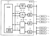
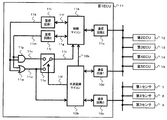
- FIG. 2 is a diagram showing an internal configuration of the autonomous traveling control unit (first ECU) 11 in the first embodiment.
- the external world recognition microcomputer (external world recognition unit) 10 b in the autonomous traveling control unit 11 is an external world of the vehicle based on information from external sensors such as the first sensor 1, the second sensor 2 or the third sensor 3. Information is recognized, and based on the recognized vehicle external world information, when the control microcomputer 11 b is reset, it is determined that the collision potential of the vehicle is high.
- control microcomputer 11b is defined as a control command generation unit that generates a control command to an external actuator (drive device) control unit.
- the autonomous traveling control unit 11 which is a traveling control device for automatic driving, has two microcomputers of an external world recognition microcomputer 10b and a control microcomputer 11b.
- the external world recognition microcomputer 10b includes a communication circuit 10c (communication circuit 0) and a communication circuit 10d (communication circuit 1).
- the control microcomputer 11b also includes a communication circuit 11c (communication circuit 2).
- the degeneration control unit 12 which operates in place of the autonomous traveling control unit 11 when the autonomous traveling control unit 11 fails includes the degeneration control microcomputer 12 b and the communication circuit 12 c (communication circuit 3).
- the degeneration control microcomputer 12b generates a degenerated control instruction from the control instruction generated by the control microcomputer 11b.
- the autonomous traveling control unit 11 includes the external world recognition microcomputer 10 b and the control microcomputer 11 b
- the degeneration control unit 12 includes the degeneration control microcomputer 12 b
- the control microcomputer 11b and the degeneration control microcomputer 12b may be disposed.
- the autonomous traveling control unit 11 may include the control microcomputer 11b and the degeneration control microcomputer 12b, and the external world recognition microcomputer 10b may be disposed in a control unit other than the autonomous traveling control unit 11.
- Sensor information (camera 1 (first sensor), radar 2 (second sensor), and vehicle position sensor 3 (third sensor), which are external sensors, is sent to the external world recognition microcomputer 10b via the communication circuit 10c. External world recognition information is transmitted.
- the external world recognition microcomputer 10b recognizes the situation of the external world based on the transmitted sensor information, and generates track information on which the host vehicle travels.
- the external world recognition microcomputer 10b can be defined as a trajectory information generation unit.
- the external world recognition microcomputer 10b transmits the generated orbit information to the control microcomputer 11b via the orbit information communication line 10k.
- the control microcomputer 11b externally receives information on an external recognition sensor such as a wheel speed sensor, an acceleration sensor, a yaw rate sensor (not shown) from the outside via the communication circuit 11c (communication circuit 2) (these information is also included in the external recognition information Are received from the external ECU (control device), and the brake control unit 13 (third ECU) and the engine control unit 14 (fourth ECU) based on the information thereof and the trajectory information calculated by the external world recognition microcomputer 10b. And generates and transmits respective actuator control commands to the power steering control unit 15 (fifth ECU).
- a monitoring circuit 11h for monitoring the control microcomputer 11b is connected to the control microcomputer 11b, and the monitoring circuit 11h is a first monitoring for detecting an abnormality in the control microcomputer 11b at an abnormality detection time T1 (first abnormality detection time). And a second monitoring unit that detects abnormality of the control microcomputer 11b at an abnormality detection time T2 (second abnormality detection time) whose detection time is longer than the abnormality detection time T1.
- the first monitoring unit and the second monitoring unit are configured such that the determination criteria for abnormality detection are different from each other.
- the judgment criteria for abnormality detection in the first monitoring unit are for minor abnormalities, and the judgment criterion for abnormality detection in the second monitoring unit is a severe abnormality compared to the judgment criterion for abnormality detection in the first monitoring unit.
- the first monitoring unit is a watchdog timer 11i (WDT unit) that determines the normality of the program operation of the control microcomputer 11b.
- the pulse output unit 11d of the control microcomputer 11b outputs high / low pulse signals of a constant cycle via the communication line 11f, and the watch dog timer 11i (WDT unit) determines the normality of the pulse output unit 11d.
- the second monitoring unit is a calculation logic check unit 11j that determines the normality of the calculation unit 11e of the control microcomputer 11b.
- the arithmetic logic collating unit 11 j periodically performs an interrogation signal (for example, an arithmetic expression using a certain random numerical value and its numerical value) by two-way communication between the monitoring circuit 11 h and the control microcomputer 11 b through the communication line 11 g. It transmits to the calculating part 11e of the control microcomputer 11b.
- the answer signal of the calculation unit 11e corresponding to the question signal is compared with the expected value calculated in advance by the calculation logic comparison unit 11j, and the normality of the control microcomputer 11b is determined.
- the second monitoring unit is a check of operation logic, and in the case of a check failure, the abnormality counter is set to count up, and the abnormality detection time can be adjusted by setting the criteria for judging the abnormality finally.
- an abnormality detection time T2 longer than the abnormality detection time T1 is set in advance.
- the first monitoring unit and the second monitoring unit are collectively referred to as a monitoring unit.
- the monitoring circuit 11h that monitors the control microcomputer 11b is a logic circuit, and can be incorporated in the external world recognition microcomputer 10b.
- the external world recognition microcomputer 10b is a microcomputer that recognizes the situation of the external world based on the transmitted sensor information and generates track information on which the host vehicle moves, and periodically calculates a collision potential with surrounding objects. There is.
- the external world recognition microcomputer 10b transfers the automatic operation control from the control microcomputer 11b to the degeneration control microcomputer 12b to the monitoring circuit 11h. Output.
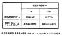
- the degeneration request signal 10f output from the degeneration request signal generating unit 10e of the external world recognition microcomputer 10b is a low output when the collision potential of the own vehicle is low, and is a specification that toggles to high when the collision potential is high.
- a control microcomputer 11b abnormality detection signal is input to the reset timing switching unit 11s of the monitoring circuit 11h from both the first monitoring unit WDT 11i and the second monitoring unit arithmetic logic comparison unit 11j. . Then, the reset timing switching unit 11s determines which one of the WDT unit 11i and the arithmetic logic comparison unit 11j is to reset the control microcomputer 11b according to the degeneration request signal 10f.
- the abnormality notification signal generation unit 11 q supplies the abnormality notification signal 11 u to the external world recognition microcomputer 10 b according to the signal supplied from the reset timing switching unit 11 s.
- FIG. 3 is a table showing reset timings of the degeneration request signal 10f, the abnormality notification signal 11u, and the control microcomputer 11b in the first embodiment of the present invention.
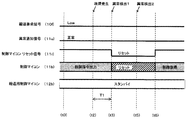
- FIG. 4 is a control shift time chart in the case of executing the degeneration operation in the first embodiment of the present invention.
- the control microcomputer 11b outputs a control command to the external actuator control unit, and the degeneration control microcomputer 12b is in the standby state.
- the degeneration request signal is Low output at the timing (t0), but becomes High due to the increase of the collision potential at the timing (t1).
- the abnormality notification signal (11u) becomes High at a timing (t3) after the abnormality detection time T1 has elapsed from the failure occurrence (an abnormality due to the WDT section 11i Detection 1)
- the control microcomputer abnormality (control command generation unit abnormality) is notified to the degeneration control microcomputer 12b via the external world recognition microcomputer 10b, the communication circuit 10d and the communication circuit 12c, and the control is transferred to the degeneration control microcomputer 12b. It is started.
- the transition preparation for the degeneration control microcomputer 12b is completed at the timing (t4) when the control transition period T3 has passed, and the control microcomputer 11b is reset at the timing (t5) when the abnormality detection time T2 has elapsed since the failure occurrence. (Abnormal detection 2 by the arithmetic logic check unit 11 j).
- the second monitoring unit is more effective even if the first monitoring unit determines an abnormality.
- the abnormality is not determined by making a deep level abnormality determination (whether or not the calculation unit 11e is abnormal), and in that case, the control microcomputer 11b is not reset at timing (t5) and the control is continued. Become.
- the noise causes the pulse output unit 11d to determine that it is abnormal, whereby the degeneration control microcomputer 12b executes degeneration control through the control transition operation, and this degeneration control operation and control by the control microcomputer 11b are performed in parallel. Will be executed.
- the brake control unit 3, the engine control unit 14, and the power steering control unit 15 are predetermined so as to give priority to the control command from the control microcomputer 11b.
- the control by the control microcomputer 11b is continued.
- the degeneration control microcomputer 12b can safely be generated without generating a blank period of control. Control transfer is possible. Further, in the case of a transient failure such as noise generation, the control is not shifted to the main degeneration control, and the control by the control microcomputer 11b can be continued to ensure safety.
- FIG. 5 is a timing chart of operation control when the collision potential of the vehicle is low.
- FIG. 5 shows the operation control when the monitoring circuit 11h detects an operation abnormality of the control microcomputer 11b under the condition that the external world recognition microcomputer 10b in the autonomous traveling control unit 11 determines that the collision potential of the own vehicle is low. Is shown. In this example, the control microcomputer 11b is reset without shifting to the degeneration control microcomputer 12b.
- the control microcomputer 11b outputs a control command to the external actuator control unit, and the degeneration control microcomputer 12b is in the standby state. If a failure occurs in the control microcomputer 11b at timing (t2) in a scene where the collision potential is low and the degeneration request signal 11u is low output, at timing (t3) after the abnormality detection time T1 has elapsed from the failure occurrence.
- the control microcomputer 11b is reset. In this case, the degeneration request signal 11u is a low output, and control is not transferred to the degeneration control microcomputer 12b, and the control microcomputer 11b returns control from reset at timing (t6) after a predetermined time has elapsed from timing (t5).
- the monitoring circuit 11h determines whether to reset the control microcomputer 11b according to the determination result of the first monitoring unit or the determination result of the second monitoring unit according to whether the degeneration request signal 10f is high or low. doing.
- control microcomputer 11b when an abnormality is detected in the control microcomputer 11b in a scene where the collision potential is low, the control microcomputer 11b is reset at an early stage, and after the time elapses, the external situation of the vehicle changes and the risk increases.
- the control command generation operation of the control microcomputer 11 b (control command generation unit) can be returned.
- the control can be safely shifted to the degeneration control microcomputer, and a vehicle control device capable of improving the safety can be realized.
- FIG. 6 is a diagram showing an internal configuration of the autonomous traveling control unit (first ECU) 11 in the second embodiment.
- FIG. 6 shows an example in which the degeneration control microcomputer 12 b is disposed in the autonomous traveling control unit 11 in addition to the external world recognition microcomputer 10 b and the control microcomputer 11 b.
- the degeneration control microcomputer 12 b and the communication circuit 12 c are disposed in the autonomous traveling control unit 11.
- the second embodiment has substantially the same configuration as the first embodiment, but the abnormality notification signal 11 u is connected to the external world recognition microcomputer 10 b and the degeneration control microcomputer 12 b in the autonomous traveling control unit 11.
- the connection of the signal line to the degeneration control microcomputer 12b of the abnormality detection signal 11u is facilitated, thereby improving the latency at the occurrence of an abnormality. effective.
- the third embodiment is an example in which the internal configuration of the autonomous traveling control unit (first ECU) 11 is the same as that of the first embodiment or the second embodiment, but the monitoring circuit 11h can change the abnormality detection time T1 and the abnormality detection time T2. is there.
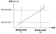
- FIG. 7 is a setting explanatory diagram of the abnormality detection criteria (determination criteria) and the detection times T1 and T2 in the third embodiment.
- the horizontal axis indicates the elapsed time from the occurrence of a failure in the control microcomputer 11b, and the vertical axis indicates the abnormality counter.
- a straight line L in which the abnormality counter increases with the passage of time is defined, and criteria 1 (judgment criterion 1) and criterion 2 (judgment criterion 2) are adjusted.
- the time at the point of intersection with L is taken as the abnormality detection time T1
- the time at the point where the criteria 2 and the straight line L intersect is taken as the abnormality detection time T2.
- Criterion 2 is larger than Criterion 1.
- the abnormality detection time T1 and the abnormality detection time T2 can be set by setting the criteria 1 and 2 for abnormality determination with respect to the abnormality counter value that counts up each time an abnormality is detected. That is, criteria 1 and 2 are set according to the number of times of anomaly detection, and criteria 2 makes the number of times of anomaly detection greater than criteria 1. Then, the abnormality detection time T1 corresponds to the criterion 1 and the abnormality detection time T2 is set to correspond to the criterion 2, thereby setting the time difference such that the abnormality time detection time T2 becomes longer than the abnormality detection time T1.
- the abnormality detection time T2 in the relationship of T2 ⁇ T1 + T3 using the abnormality detection time T1 and the control transition period T3 of the degeneration control microcomputer 12b, the blank period of control by the control microcomputer 11b reset is eliminated. Thus, the reliability of the control circuit can be improved.
- the fourth embodiment is a configuration example using two monitoring circuits and a logic gate.
- FIG. 8 is a diagram showing an internal configuration of the autonomous traveling control unit (first ECU) 11 in the fourth embodiment.
- a monitoring circuit 11i for monitoring the control microcomputer 11b and a monitoring circuit 11j (second monitoring unit) are connected to the control microcomputer 11b.
- the monitoring circuit 11i is a watchdog timer that determines the normality of the program operation of the control microcomputer 11b
- the monitoring circuit 11j is an arithmetic logic collating unit that determines the normality of the arithmetic unit 11e of the control microcomputer 11b. And have different monitoring means.
- the normality judgment results of the monitoring circuit 11i (first monitoring unit) and the monitoring circuit 11j (second monitoring unit) are respectively the signal 11k and the signal 11m, and the input terminal of the AND gate 11p and the input terminal of the OR gate 11w.
- the gate output of the OR gate 11w responds when an abnormality is detected in one of the monitoring circuits 11i and 11j, and an abnormality notification signal 11u is notified to the external world recognition microcomputer 10b.
- the output signal 11v of the AND gate 11p responds when abnormality is detected in the monitoring circuits of both the monitoring circuit 11i and the monitoring circuit 11j, and more accurate abnormality detection is possible.
- reaction timing differs between the gate output of the OR gate 11w and the output of the AND gate 11p, it is possible to generate the abnormality detection time T1 and the abnormality detection time T2 as in the first embodiment.
- the external world recognition microcomputer 10b degenerates whether to shift the automatic operation control from the control microcomputer 11b to the degeneration control microcomputer 12b when an abnormality occurs in the control microcomputer 11b and resets the control microcomputer 11b.
- the request signal 10 f is output to the reset timing switching circuit 11 s.
- FIG. 9 is a table showing the degeneration request signal 10f and the reset timing of the control microcomputer 11b in the fourth embodiment.
- the degeneration request signal 10f when the degeneration request signal 10f is High, the reset timing switching circuit 11s is connected to the signal 11v side, and when an abnormality is detected in the control microcomputer 11b, the control microcomputer 11b is reset at an abnormality detection time T2.
- the degeneration request signal 10f when an abnormality is detected in the control microcomputer 11b, the signal 11u is toggled so that the external world recognition microcomputer 10b outputs an abnormality detection signal to the degeneration control unit 12, and the control microcomputer 11b It is reset at the abnormality detection time T2.
- control can be safely transferred to the degeneration control microcomputer 12b.
- control is not transferred and continues to ensure safety.
- the present invention is not limited to a car, but can be applied to a two-wheeled vehicle, a luggage carrier for a factory, a traveling robot, etc. is there.
- the fifth embodiment is an example of an electronic control system applicable to various mobile objects.
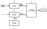
- FIG. 10 is an operation functional block diagram of the electronic control system (autonomous traveling control system) of the fifth embodiment.
- the electronic control system receives information from the external world recognition unit 20b, the first control unit 23 for driving the actuator (drive device) 24, and the external world recognition unit 20b, and sends a control command to the first control unit 23.
- a second control unit 21b for transmitting and a third control unit 22 for performing a control shift to command the first control unit 23 when the second control unit 21b detects an abnormality are provided.
- the third control unit 22b After the control shifts to the control, the second control unit 21b itself is reset.
- the second control unit 21b When the second control unit 21b detects an abnormality in the second control unit 21b itself when the external recognition unit 20 determines that the collision potential with the external object is low, the second control unit 21b immediately 2) Reset the control unit 21b itself, and then return the control command operation.
- the third control unit 22 b When the abnormality signal is supplied from the second control unit 21 b, the third control unit 22 b outputs a control command at the time of degeneration to the first control unit 23.
- FIG. 11 is an operation timing chart when a failure occurs in the fifth embodiment.
- the abnormality detection 1 is the detection of the abnormality of the program operation determined by the first monitoring unit similar to the first to fourth embodiments described above.
- the third control unit 22b outputs a control command at the time of degeneration to the first control unit 23. Thereafter, an abnormality is detected at time (t5) (abnormal detection 2), and the second control unit 21b resets the second control unit 21b itself.
- the abnormality detection 2 is detection of abnormality of the calculation unit determined by the second monitoring unit similar to the first to fourth embodiments described above.
- abnormality detection 1 is the detection of the abnormality of the program operation determined by the first monitoring unit similar to the first to fourth embodiments described above.
- the abnormality detection 2 is detection of abnormality of the calculation unit determined by the second monitoring unit similar to the first to fourth embodiments described above.
- the second control unit 21b restores control.
- the third control unit 22b maintains the standby state in the external environment where the collision potential is low.
- the third control unit 22b is not generated without generating a blank period of control. It is possible to shift the control safely, eliminate the blank period of control, and improve the reliability of the control circuit.
- the second control unit 21b when an abnormality is detected in the second control unit 21b in a scene where the collision potential is low, the second control unit 21b is reset early, before the external situation of the vehicle changes after a lapse of time and the risk increases. Control can be restored.
- control can be safely transferred to the degeneration control microcomputer, and an electronic control system capable of improving the safety can be realized.
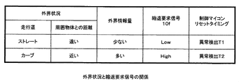
- FIG. 12 is a table showing the relationship between the external world situation and the degeneration request signal. The switching of the reset timing of the control microcomputer 11b according to the external world situation and the amount of external world information will be described with reference to FIG.
- the outside world recognition microcomputer 10b determines the collision potential between the own vehicle and the surrounding object (collision possibility) Since it can be judged that is low, the degeneration request is not made (the degeneration request signal 10f is set to Low output), and the control microcomputer 11b is reset at the abnormality detection time T1.
- the external world recognition microcomputer 10b regularly generates a forecast of a track along which the vehicle travels. Then, the collision potential in the traveling track of the generated own vehicle is determined. If the traveling road is a straight line, it is possible to estimate that the collision potential is low (judged), considering that the track itself does not substantially change even in a blank section of control when the control microcomputer 11b is reset even during control. .
- the collision possibility can be determined according to the shape of the traveling road predicted that the host vehicle travels.
- the traveling road is a curve as the outside world situation
- the collision potential with the vehicle is considered to be high if the distance to the object surrounding the vehicle is short, or if the amount of information of the outside world is large.
- Make a request (the degeneration request signal is output High).
- the transition control to the degeneration control is started by notifying the degeneration control microcomputer 12b of the abnormality in the degeneration control microcomputer 12b at the abnormality detection time T1, and the control microcomputer 11b is reset at the abnormality detection time T2 after the transition preparation is completed.
- the collision possibility can be determined according to the amount of information of the outside world where the vehicle travels.
- the degeneration control microcomputer 12b is caused to start preparation for transition early, and the control microcomputer 11b is reset at abnormality detection time T2 after completion of preparation for transition.
- the possibility of collision with the host vehicle can also be determined only by the shape of the traveling road, only by the distance to the surrounding object, or only by the amount of external world information.
- Anomaly notification signal generation unit 11 r ... Reset signal, 11 s ... Reset timing switching circuit, 11 t ... Reset Generation unit, 11u: abnormality notification signal, 11w: OR gate, 20b: external recognition unit, 21b: second control unit, 22b: third control unit, 23: first Control unit, 24 ... Actuator
Landscapes
- Engineering & Computer Science (AREA)
- Automation & Control Theory (AREA)
- Mechanical Engineering (AREA)
- Transportation (AREA)
- Human Computer Interaction (AREA)
- Radar, Positioning & Navigation (AREA)
- Remote Sensing (AREA)
- Physics & Mathematics (AREA)
- General Physics & Mathematics (AREA)
- Control Of Driving Devices And Active Controlling Of Vehicle (AREA)
- Traffic Control Systems (AREA)
Abstract
La présente invention concerne un dispositif de commande de véhicule avec lequel une commande peut être transférée en toute sécurité à un micro-ordinateur de commande de dégénérescence, et la sécurité peut être améliorée même lorsqu'une anomalie fonctionnelle se produit dans une unité de traitement de calcul dans un dispositif de commande. Ce dispositif de commande de véhicule est pourvu d'un micro-ordinateur de reconnaissance externe 10b, d'un micro-ordinateur de commande 11b qui délivre en sortie une instruction de commande à un dispositif de commande d'actionneur, et d'un micro-ordinateur de commande 12b de dégénérescence auquel la commande est transférée lorsqu'une anomalie se produit dans le micro-ordinateur de commande 11b. En calculant un potentiel de collision, sur la base d'informations provenant d'une source externe, le micro-ordinateur de reconnaissance externe 10b évalue s'il faut réinitialiser le micro-ordinateur de commande 11b lorsqu'une anomalie se produit dans le micro-ordinateur de commande 11b ou transférer la commande au micro-ordinateur de commande 12b de dégénérescence.
Priority Applications (3)
| Application Number | Priority Date | Filing Date | Title |
|---|---|---|---|
| JP2019562902A JP6802391B2 (ja) | 2017-12-25 | 2018-12-04 | 車両制御装置および電子制御システム |
| US16/956,386 US11247702B2 (en) | 2017-12-25 | 2018-12-04 | Vehicle control device and electronic control system |
| DE112018006016.0T DE112018006016T5 (de) | 2017-12-25 | 2018-12-04 | Fahrzeugsteuervorrichtung und elektronisches Steuersystem |
Applications Claiming Priority (2)
| Application Number | Priority Date | Filing Date | Title |
|---|---|---|---|
| JP2017248462 | 2017-12-25 | ||
| JP2017-248462 | 2017-12-25 |
Publications (1)
| Publication Number | Publication Date |
|---|---|
| WO2019131002A1 true WO2019131002A1 (fr) | 2019-07-04 |
Family
ID=67063512
Family Applications (1)
| Application Number | Title | Priority Date | Filing Date |
|---|---|---|---|
| PCT/JP2018/044483 Ceased WO2019131002A1 (fr) | 2017-12-25 | 2018-12-04 | Dispositif de commande de véhicule et système de commande électronique |
Country Status (4)
| Country | Link |
|---|---|
| US (1) | US11247702B2 (fr) |
| JP (1) | JP6802391B2 (fr) |
| DE (1) | DE112018006016T5 (fr) |
| WO (1) | WO2019131002A1 (fr) |
Cited By (2)
| Publication number | Priority date | Publication date | Assignee | Title |
|---|---|---|---|---|
| JP2022139379A (ja) * | 2021-03-11 | 2022-09-26 | 株式会社Zmp | 自動運転車両 |
| JP2022173705A (ja) * | 2021-05-10 | 2022-11-22 | 三菱電機株式会社 | 車両制御システムおよび車両制御方法 |
Families Citing this family (15)
| Publication number | Priority date | Publication date | Assignee | Title |
|---|---|---|---|---|
| US11538287B2 (en) * | 2019-09-20 | 2022-12-27 | Sonatus, Inc. | System, method, and apparatus for managing vehicle data collection |
| US11411823B2 (en) * | 2019-09-20 | 2022-08-09 | Sonatus, Inc. | System, method, and apparatus to support mixed network communications on a vehicle |
| US12261747B2 (en) * | 2019-09-20 | 2025-03-25 | Sonatus, Inc. | System, method, and apparatus to execute vehicle communications using a zonal architecture |
| FR3103219B1 (fr) * | 2019-11-19 | 2021-10-08 | Vitesco Technologies | Procédé de gestion des anomalies sporadiques d’un système de motorisation d’un véhicule automobile |
| US12094259B2 (en) | 2020-03-06 | 2024-09-17 | Sonatus, Inc. | System, method, and apparatus for managing vehicle automation |
| US11772583B2 (en) | 2020-03-06 | 2023-10-03 | Sonatus, Inc. | System, method, and apparatus for managing vehicle automation |
| US12211323B2 (en) | 2020-03-06 | 2025-01-28 | Sonatus, Inc. | System, method, and apparatus for managing vehicle automation |
| US12528442B2 (en) * | 2020-03-06 | 2026-01-20 | Sonatus, Inc. | System, method, and apparatus for managing vehicle data collection |
| US12403921B2 (en) | 2020-03-06 | 2025-09-02 | Sonatus, Inc. | System, method, and apparatus for managing vehicle automation |
| US12573245B2 (en) | 2020-03-06 | 2026-03-10 | Sonatus, Inc. | System, method, and apparatus for managing vehicle automation |
| US12103479B2 (en) * | 2020-03-06 | 2024-10-01 | Sonatus, Inc. | System, method, and apparatus for managing vehicle automation |
| US11321163B2 (en) * | 2020-03-26 | 2022-05-03 | Wipro Limited | Device and method for monitoring functional safety in integrated circuits (ICS) |
| JP7406432B2 (ja) * | 2020-03-31 | 2023-12-27 | 本田技研工業株式会社 | 移動体制御装置、移動体制御方法、およびプログラム |
| WO2022009497A1 (fr) * | 2020-07-06 | 2022-01-13 | 日立Astemo株式会社 | Dispositif de commande électronique |
| JP2024112141A (ja) * | 2023-02-07 | 2024-08-20 | トヨタ自動車株式会社 | 車両の運動マネージャ、車両の制御方法、及び車両の制御プログラム |
Citations (3)
| Publication number | Priority date | Publication date | Assignee | Title |
|---|---|---|---|---|
| JP2003115847A (ja) * | 2001-10-09 | 2003-04-18 | Denso Corp | 制御システム及び冗長系信号処理装置 |
| JP6189004B1 (ja) * | 2017-01-24 | 2017-08-30 | 三菱電機株式会社 | 共用バックアップユニットおよび制御システム |
| JP2017222328A (ja) * | 2016-06-17 | 2017-12-21 | 株式会社デンソー | 車両制御装置 |
Family Cites Families (16)
| Publication number | Priority date | Publication date | Assignee | Title |
|---|---|---|---|---|
| US8793046B2 (en) * | 2012-06-01 | 2014-07-29 | Google Inc. | Inferring state of traffic signal and other aspects of a vehicle's environment based on surrogate data |
| JP6220232B2 (ja) | 2013-11-08 | 2017-10-25 | 日立オートモティブシステムズ株式会社 | 車両の制御装置 |
| US9547989B2 (en) * | 2014-03-04 | 2017-01-17 | Google Inc. | Reporting road event data and sharing with other vehicles |
| US10354330B1 (en) * | 2014-05-20 | 2019-07-16 | State Farm Mutual Automobile Insurance Company | Autonomous feature use monitoring and insurance pricing |
| US10168193B2 (en) * | 2015-01-07 | 2019-01-01 | Infineon Technologies Ag | Sensor with switching matrix switch |
| US10345809B2 (en) * | 2015-05-13 | 2019-07-09 | Uber Technologies, Inc. | Providing remote assistance to an autonomous vehicle |
| US9930120B2 (en) * | 2015-07-17 | 2018-03-27 | Enrique Gutierrez | Infrastructure-to-vehicle communication system and method |
| US9716565B2 (en) * | 2015-11-12 | 2017-07-25 | Ben Mandeville-Clarke | System, apparatus, and method for generating and transmitting an interruption signal to a substantially autonomous vehicle |
| US10281923B2 (en) * | 2016-03-03 | 2019-05-07 | Uber Technologies, Inc. | Planar-beam, light detection and ranging system |
| US9990548B2 (en) * | 2016-03-09 | 2018-06-05 | Uber Technologies, Inc. | Traffic signal analysis system |
| JP6727980B2 (ja) * | 2016-08-08 | 2020-07-22 | 株式会社東芝 | 通信装置および通信方法 |
| US10255582B2 (en) * | 2016-08-18 | 2019-04-09 | Amazon Technologies, Inc. | AGV traffic management system |
| DE102016218012A1 (de) * | 2016-09-20 | 2018-03-22 | Volkswagen Aktiengesellschaft | Verfahren für eine Datenverarbeitungsanlage zur Erhaltung eines Betriebszustands eines ersten autonomen Fahrzeugs sowie Verfahren für eine Datenverarbeitungsanlage zum Verwalten einer Mehrzahl autonomer Fahrzeuge |
| US10262475B2 (en) * | 2017-01-19 | 2019-04-16 | Ford Global Technologies, Llc | Vehicle sensor health monitoring |
| US11042155B2 (en) * | 2017-06-06 | 2021-06-22 | Plusai Limited | Method and system for closed loop perception in autonomous driving vehicles |
| US20190163176A1 (en) * | 2017-11-30 | 2019-05-30 | drive.ai Inc. | Method for transferring control of an autonomous vehicle to a remote operator |
-
2018
- 2018-12-04 WO PCT/JP2018/044483 patent/WO2019131002A1/fr not_active Ceased
- 2018-12-04 US US16/956,386 patent/US11247702B2/en active Active
- 2018-12-04 DE DE112018006016.0T patent/DE112018006016T5/de active Granted
- 2018-12-04 JP JP2019562902A patent/JP6802391B2/ja active Active
Patent Citations (3)
| Publication number | Priority date | Publication date | Assignee | Title |
|---|---|---|---|---|
| JP2003115847A (ja) * | 2001-10-09 | 2003-04-18 | Denso Corp | 制御システム及び冗長系信号処理装置 |
| JP2017222328A (ja) * | 2016-06-17 | 2017-12-21 | 株式会社デンソー | 車両制御装置 |
| JP6189004B1 (ja) * | 2017-01-24 | 2017-08-30 | 三菱電機株式会社 | 共用バックアップユニットおよび制御システム |
Cited By (4)
| Publication number | Priority date | Publication date | Assignee | Title |
|---|---|---|---|---|
| JP2022139379A (ja) * | 2021-03-11 | 2022-09-26 | 株式会社Zmp | 自動運転車両 |
| JP7637973B2 (ja) | 2021-03-11 | 2025-03-03 | 株式会社Zmp | 自動運転車両 |
| JP2022173705A (ja) * | 2021-05-10 | 2022-11-22 | 三菱電機株式会社 | 車両制御システムおよび車両制御方法 |
| JP7204818B2 (ja) | 2021-05-10 | 2023-01-16 | 三菱電機株式会社 | 車両制御システムおよび車両制御方法 |
Also Published As
| Publication number | Publication date |
|---|---|
| US11247702B2 (en) | 2022-02-15 |
| JP6802391B2 (ja) | 2020-12-16 |
| DE112018006016T5 (de) | 2020-10-29 |
| JPWO2019131002A1 (ja) | 2020-07-27 |
| US20200361487A1 (en) | 2020-11-19 |
Similar Documents
| Publication | Publication Date | Title |
|---|---|---|
| WO2019131002A1 (fr) | Dispositif de commande de véhicule et système de commande électronique | |
| JP6777761B2 (ja) | 車両制御装置 | |
| US12055933B2 (en) | Fault-tolerant control of an autonomous vehicle with multiple control lanes | |
| US9393967B2 (en) | Method and device for operating a motor vehicle in an automated driving operation | |
| US11787425B2 (en) | Electronic control device and in-vehicle device | |
| JP6802374B2 (ja) | 車両制御装置および車両制御システム | |
| US11492009B2 (en) | Vehicle control device | |
| JP6861302B2 (ja) | 車両制御装置および電子制御システム | |
| CN107908186B (zh) | 用于控制无人驾驶车辆运行的方法及系统 | |
| JP6675487B2 (ja) | 車両制御装置 | |
| US20170153644A1 (en) | Action Planning Device | |
| JP2019128639A (ja) | 電子制御装置 | |
| US10324636B2 (en) | Fail-operational system design pattern based on software code migration | |
| EP3627247B1 (fr) | Architecture de commande pour véhicule | |
| JP7122494B2 (ja) | 車両制御システム、車両統合制御装置、電子制御装置、ネットワーク通信装置、車両制御方法、および、車両制御プログラム | |
| US11570250B2 (en) | Communication system and method for communication for a motor vehicle | |
| CN112636881A (zh) | 一种信号切换方法、装置及车辆 | |
| JP6926324B2 (ja) | 電子制御装置 | |
| JP2019064352A (ja) | 電子制御装置 |
Legal Events
| Date | Code | Title | Description |
|---|---|---|---|
| 121 | Ep: the epo has been informed by wipo that ep was designated in this application |
Ref document number: 18894640 Country of ref document: EP Kind code of ref document: A1 |
|
| WWE | Wipo information: entry into national phase |
Ref document number: 2019562902 Country of ref document: JP |
|
| 122 | Ep: pct application non-entry in european phase |
Ref document number: 18894640 Country of ref document: EP Kind code of ref document: A1 |