WO2019131280A1 - 車両用乗員拘束装置 - Google Patents
車両用乗員拘束装置 Download PDFInfo
- Publication number
- WO2019131280A1 WO2019131280A1 PCT/JP2018/046349 JP2018046349W WO2019131280A1 WO 2019131280 A1 WO2019131280 A1 WO 2019131280A1 JP 2018046349 W JP2018046349 W JP 2018046349W WO 2019131280 A1 WO2019131280 A1 WO 2019131280A1
- Authority
- WO
- WIPO (PCT)
- Prior art keywords
- width direction
- vehicle width
- vehicle
- belt
- surface portion
- Prior art date
- Legal status (The legal status is an assumption and is not a legal conclusion. Google has not performed a legal analysis and makes no representation as to the accuracy of the status listed.)
- Ceased
Links
Images

Classifications
-
- B—PERFORMING OPERATIONS; TRANSPORTING
- B60—VEHICLES IN GENERAL
- B60N—SEATS SPECIALLY ADAPTED FOR VEHICLES; VEHICLE PASSENGER ACCOMMODATION NOT OTHERWISE PROVIDED FOR
- B60N2/00—Seats specially adapted for vehicles; Arrangement or mounting of seats in vehicles
- B60N2/68—Seat frames
- B60N2/688—Particular seat belt attachment and guiding
-
- B—PERFORMING OPERATIONS; TRANSPORTING
- B60—VEHICLES IN GENERAL
- B60R—VEHICLES, VEHICLE FITTINGS, OR VEHICLE PARTS, NOT OTHERWISE PROVIDED FOR
- B60R22/00—Safety belts or body harnesses in vehicles
- B60R22/18—Anchoring devices
-
- B—PERFORMING OPERATIONS; TRANSPORTING
- B60—VEHICLES IN GENERAL
- B60R—VEHICLES, VEHICLE FITTINGS, OR VEHICLE PARTS, NOT OTHERWISE PROVIDED FOR
- B60R22/00—Safety belts or body harnesses in vehicles
- B60R22/18—Anchoring devices
- B60R22/26—Anchoring devices secured to the seat
-
- B—PERFORMING OPERATIONS; TRANSPORTING
- B60—VEHICLES IN GENERAL
- B60N—SEATS SPECIALLY ADAPTED FOR VEHICLES; VEHICLE PASSENGER ACCOMMODATION NOT OTHERWISE PROVIDED FOR
- B60N2/00—Seats specially adapted for vehicles; Arrangement or mounting of seats in vehicles
- B60N2/02—Seats specially adapted for vehicles; Arrangement or mounting of seats in vehicles the seat or part thereof being movable, e.g. adjustable
- B60N2/20—Seats specially adapted for vehicles; Arrangement or mounting of seats in vehicles the seat or part thereof being movable, e.g. adjustable the back-rest being tiltable, e.g. to permit easy access
-
- B—PERFORMING OPERATIONS; TRANSPORTING
- B60—VEHICLES IN GENERAL
- B60N—SEATS SPECIALLY ADAPTED FOR VEHICLES; VEHICLE PASSENGER ACCOMMODATION NOT OTHERWISE PROVIDED FOR
- B60N2/00—Seats specially adapted for vehicles; Arrangement or mounting of seats in vehicles
- B60N2/90—Details or parts not otherwise provided for
- B60N2/919—Positioning and locking mechanisms
-
- B—PERFORMING OPERATIONS; TRANSPORTING
- B60—VEHICLES IN GENERAL
- B60R—VEHICLES, VEHICLE FITTINGS, OR VEHICLE PARTS, NOT OTHERWISE PROVIDED FOR
- B60R22/00—Safety belts or body harnesses in vehicles
- B60R22/18—Anchoring devices
- B60R2022/1818—Belt guides
Definitions
- the disclosed technology relates to a vehicle occupant restraint apparatus provided with a seat belt capable of restraining an occupant seated in a rear seat.
- a vehicle such as a car equipped with a rear seat is provided with a passenger restraining device for protecting the passenger by restraining the passenger seated on the rear seat at the time of a collision, and the passenger restraint device is generally seated on the rear seat
- a three-point seat belt device for restraining the upper torso and the waist of the occupant is provided.
- the three-point type seat belt device is configured by extending a seat belt pulled out from a retractor disposed outside in the vehicle width direction on the rear side of the vehicle from the rear seat, through the front side of the seat back of the rear seat and in the vehicle width direction of the seat cushion of the rear seat. While fixing to the belt anchor arranged on the outside, the tongue plate mounted on the seat belt is engaged with the buckle fixed on the inside in the vehicle width direction of the seat cushion, and the upper torso of the occupant seated on the rear seat and It is designed to restrain the lower back.
- the retractor retracts the seat belt at the time of a collision to reduce the slack of the seat belt and pretensioner mechanism that takes up the seat belt to restrain the occupant, and at the time of a collision, the load is applied to the seat belt more than a predetermined load.
- One having a load limiter mechanism for loosening a seat belt is generally used.
- a belt guide for inserting and holding the seat belt pulled out from the retractor in the vehicle longitudinal direction on the outer side in the vehicle width direction at the top of the seatback of the rear seat is disposed. It is known that a seat belt having a guide inserted therein extends diagonally downward from the vicinity of a shoulder on the outer side in the vehicle width direction of the occupant to restrain the occupant.
- Patent Document 1 discloses that a belt guide is urged inward in the vehicle width direction by an urging spring at the time of a collision to move inward in the vehicle width direction along a slide rail fixed to a seatback. ing.
- the occupant seated in the rear seat is a car during a collision such as an offset collision in which one side in the vehicle width direction at the front of the vehicle collides frontally.
- the seat belt may be removed from the shoulder of the occupant by being moved inward in the width direction.
- the seat is biased inward in the vehicle width direction by the biasing spring at the time of a collision to move the belt guide inward in the vehicle width direction along the slide rail fixed to the seat back.
- the biasing spring it is relatively simple because the structure for biasing the belt guide by the biasing spring and moving along the slide rail becomes complicated. It is desirable to move the belt guide inward in the vehicle width direction at the time of a collision.
- the inner longitudinal surface portion of the belt guide disposed at the outer side in the vehicle width direction at the upper part of the rear seat is configured to be tilted by the load inward in the vehicle width direction input from the seat belt at the time of a collision. It is conceivable to move the seat belt inward in the vehicle width direction to suppress the seat belt from coming off the shoulder of the occupant.
- the lock guide is disposed inside the belt guide.
- the lock release switch is pressed by the belt guide, and the seatback of the rear seat may fall to the front side of the vehicle body.
- the disclosed technology improves the protection performance of the occupant by moving the seat belt inward in the vehicle width direction at the time of a collision in a vehicle in which a lock release switch for the rear seat is disposed inward of the belt guide in the vehicle width direction. It is an object of the present invention to provide a vehicle occupant restraining device capable of preventing the belt guide from pressing the lock release switch as well as the vehicle occupant restraint system.
- a vehicle occupant restraint system to which the disclosed technology is applied is characterized by the following configuration.
- An occupant restraint apparatus for a vehicle comprising a seat belt capable of restraining an occupant seated in a rear seat having a seat cushion and a seat back, the seat belt being disposed on the outer side in the vehicle width direction at an upper portion of the seat back And a belt guide for holding the seat belt in the longitudinal direction of the vehicle body, the belt guide supporting the seat belt from the lower side of the vehicle body and guiding the seat belt, and the vehicle guide in the vehicle width direction of the guide And an inner longitudinal surface portion extending to the upper side of the vehicle body, wherein the inner longitudinal surface portion is configured to be tiltable inward in the vehicle width direction by an inward load in the vehicle width direction input from the seat belt at the time of a collision
- a lock release switch is provided on the upper side of the belt inward in the vehicle width direction from the belt guide to unlock the seatback in the upright state Is characterized in that the regulating member, wherein the inner longitudinal face portion is restricted from being tilted a predetermined or more inward in the vehicle width direction between the
- the inner longitudinal surface portion includes an inclined surface portion which is higher in the vehicle width direction from the guide portion, and the regulating member is inclined inward in the vehicle width direction to face the inner longitudinal surface portion. It may be provided with a face portion.
- the restriction member may be provided at a position overlapping the belt guide in the vehicle width direction.
- the belt guide further includes an outer longitudinal surface portion provided on the outer side in the vehicle width direction of the guide portion and extending upward on the vehicle body, and the inner longitudinal surface portion is closer to the seat belt than the outer longitudinal surface portion. It may be configured as a fragile portion that is vulnerable to the input load in the vehicle width direction.
- a vehicle occupant restraint apparatus having a seat belt capable of restraining an occupant seated in a rear seat includes a belt guide disposed on the outer side in the vehicle width direction at the top of the seat back, and a belt guide
- the inner longitudinal surface portion provided on the inner side in the vehicle width direction of the guide portion for supporting the seat belt from the lower side of the vehicle body can be tilted inward in the vehicle width direction by the load inward in the vehicle width direction input from the seat belt Configured
- the inner longitudinal surface portion of the belt guide is inclined inward in the vehicle width direction by the seat belt as the occupant moves.
- the seat belt can be moved inward in the vehicle width direction to improve the protection performance of the occupant.
- the restricting member is prevented from inclining the inner longitudinal surface portion by a predetermined amount or more. It is possible to prevent the belt guide from pressing the unlocking switch.
- the seat belt is moved inward in the vehicle width direction at the time of a collision to improve occupant protection performance. It is possible to prevent pressing the lock release switch.
- the inner longitudinal surface portion includes an inclined surface portion that is higher in the vehicle width direction from the guide portion, and the restriction member includes an inclined surface portion that faces the inner longitudinal surface portion and is higher in the vehicle width direction.
- the inclined surface portion of the inner longitudinal surface portion can be brought into contact with the inclined surface portion of the regulating member to effectively restrict the tilting of the inner longitudinal surface portion, and the above effect can be effectively exhibited.
- the regulating member can be disposed in the space below the belt guide at the upper portion of the seatback, and the belt guide and the regulation The members can be made compact in the vehicle width direction.
- the belt guide is configured such that the inner longitudinal surface portion is formed as a fragile portion that is more fragile than the outer longitudinal surface portion, along with the movement of the occupant when the occupant is moved inward in the vehicle width direction at the time of a collision
- the inner longitudinal surface portion can be inclined relatively easily inward in the vehicle width direction by the seat belt, and the above-mentioned effect can be effectively obtained.
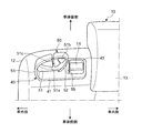
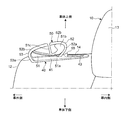
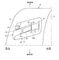
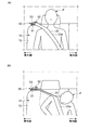
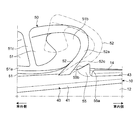
- FIG. 1 is a perspective view showing a rear portion of a vehicle body provided with a vehicle occupant restraint system according to an embodiment. It is a perspective view showing the upper part of a backseat sheet. It is a front view showing the upper part of a backseat. It is a top view which shows the upper part of a backseat. It is an explanatory view for explaining movement of a seat belt at the time of a collision. It is a principal part enlarged view which expands and shows the principal part of the upper part of a backseat.
- vehicle width direction is the width direction of the vehicle and corresponds to the left-right direction of the vehicle body.
- Outside in the vehicle width direction is a side relatively facing the outside in the vehicle width direction
- inside in the vehicle width direction is a side relatively facing the inside in the vehicle width direction.
- FIG. 1 is a perspective view showing a rear portion of a vehicle body provided with a vehicle occupant restraint system to which the disclosed technology is applied.
- the rear seat 2 is disposed at the rear of the vehicle body at the rear of the driver's seat and front passenger seat.
- a luggage space 3 is formed on the rear side of the seat 2 on the vehicle body.
- the rear seat 2 is divided into a rear seat 10 on the right side of the vehicle body and a rear seat 20 on the left side of the vehicle body.
- the rear seat 10 on the right side of the vehicle body and the rear seat 20 on the left side of the vehicle body are formed substantially symmetrically in the vehicle width direction, and hereinafter, the rear seat 10 on the right side of the vehicle body will be described.
- the rear seat 10 has a seat cushion 11, a seat back 12 and a headrest 13.
- the seat back 12 is configured to be pivotable in a standing state extending upward from the rear of the seat cushion 11 and a forward tilting state in which the seat cushion 11 is turned to the front side from the standing state and extends to the front side of the vehicle. There is.
- the rear seat 10 is also configured to lock the seat back 12 in an upright state by a locking mechanism (not shown).
- a lock release switch 14 is disposed on the upper side of the seatback 12 at the outer side in the vehicle width direction to release the lock of the seatback 12 in the upright state by the lock mechanism.
- the rear seat 10 is provided with an occupant restraint system 30 for protecting the occupant seated on the rear seat 10, and the occupant restraint system 30 restrains the upper torso and the waist of the occupant seated on the rear seat 10.
- a three-point seat belt device 31 for protecting the occupant is provided.
- the seat belt device 31 can be a retractor 32 disposed outside in the vehicle width direction on the rear side of the rear seat 10 with respect to the vehicle body, and a seat capable of restraining an occupant pulled out from the retractor 32 to the front side of the vehicle body and seated on the rear seat 10.
- a belt 33 and a belt anchor (not shown) which is disposed on the outer side in the vehicle width direction of the seat cushion 11 and to which the front end portion of the seat belt 33 is connected are provided.
- the retractor 32 is configured to be able to pull out the seat belt 33 to the front side of the vehicle body, and reduces the slack of the seat belt 33 at the time of a collision to thereby retract the seat belt 33 so as to restrain the occupant. And a load limiter mechanism for loosening the seat belt 33 so that no load exceeding a predetermined value acts on the seat belt.
- the seat belt 33 is formed in a belt shape by weaving synthetic fibers such as nylon, and is detachably attached to a buckle 34 fixed on the inner side in the vehicle width direction of the seat cushion 11 at an intermediate portion of the seat belt 33 pulled out from the retractor 32.
- a tongue plate 35 to be engaged is mounted.
- the seat belt device 31 engages the tongue plate 35 mounted on the seat belt 33 pulled out from the retractor 32 to the front side of the vehicle body from the front side of the vehicle body of the occupant seated on the rear seat 10 to the buckle 34.
- the upper torso and the waist of the seated occupant are restrained to protect the occupant.
- the seat belt 33 is a waist portion located inward in the vehicle width direction from a shoulder located outside in the vehicle width direction.
- the occupant restraint system 30 also includes a belt guide 50 disposed outside in the vehicle width direction at the upper portion of the seat back 12 of the rear seat 10, and the belt guide 50 takes the seat belt 33 drawn from the retractor 32 in the vehicle longitudinal direction. And is held at a predetermined position on the outer side in the vehicle width direction at the upper part of the seat back 12.
- FIG. 2 is a perspective view showing the upper portion of the rear seat
- FIG. 3 is a front view showing the upper portion of the rear seat
- FIG. 4 is a plan view showing the upper portion of the rear seat. 2 to 4 show the outer side in the vehicle width direction at the upper portion of the rear seat 10 shown in FIG.
- the belt guide 50 is integrated with a guide member 40 disposed on the outer side in the vehicle width direction at the upper portion of the seatback 12 of the rear seat 10 outside the head width 13 in the vehicle width direction. It is formed.
- the guide member 40 is integrally formed of a resin material, and includes a base portion 41 extending in a substantially horizontal direction. As shown in FIG. 4, the base portion 41 is formed in a substantially parallelogram in plan view, and is fixed to a seat back frame (not shown) made of a metal pipe member disposed in the seat back 12. It is fixed by
- the base portion 41 of the guide member 40 is provided with a belt guide 50 for inserting and holding the seat belt 33 in the longitudinal direction of the vehicle body outside the base portion 41 in the vehicle width direction.
- a switch receiving hole 43 for receiving the lock release switch 14 is provided on the side of the headrest 13 which is the inner side in the vehicle width direction.
- the switch accommodation hole 43 of the base portion 41 is opened in a substantially parallelogram in a plan view, and the lock release switch 14 formed in a substantially parallelogram in the plan view is biased to the upper side of the vehicle body in the switch accommodation hole 43 In the state, it is fitted and held so as to be movable in the vertical direction of the vehicle body so that the upper surface is substantially flush with the upper surface of the base portion 41.
- the lock release switch 14 releases the lock of the upright state of the seat back 12 by being pressed downward of the vehicle body, and can rotate the seat back 12 to the front side of the vehicle body to be in the forward tilt state. There is.
- the belt guide 50 supports the seat belt 33 from the lower side of the vehicle body to guide the seat belt, a guide 51 for guiding the seat belt, an inner longitudinal surface 52 provided on the inner side in the vehicle width direction of the guide 51 and extending upward on the vehicle body An outer side surface portion 53 is provided on the outer side in the vehicle width direction of 51 and extends to the upper side of the vehicle body.
- the guide portion 51 is provided so as to have a predetermined width in the longitudinal direction of the vehicle body on the center side in the longitudinal direction of the vehicle body in the base portion 41 of the guide member 40 and extend upward on the vehicle body.
- an insertion hole portion 51a for inserting the seat belt 33 in the front-rear direction of the vehicle body is formed.
- the insertion hole 51a extends in the vehicle width direction larger than the width of the seat belt 33, and is formed in a slit shape with a predetermined gap in the vertical direction of the vehicle body.
- the inside in the vehicle width direction of the insertion hole 51 a is closed by the inside longitudinal surface 52, and the outside in the vehicle width direction of the insertion hole 51 a is closed by the outside longitudinal surface 53.
- the insertion hole portion 51a is formed to be convexly curved downward toward the vehicle body from the outer side in the vehicle width direction toward the inner side in the vehicle width direction, and a belt extending upward on the vehicle body at an end portion in the vehicle width direction of the insertion hole portion 51a.
- the accommodating part 51b is provided.
- the belt accommodating portion 51b is formed in a substantially oval shape in a front view, and has a size that allows the seat belt 33 to be rounded and accommodated when the seat belt 33 is moved inward in the vehicle width direction along the insertion hole 51a at the time of a collision. It is formed.
- a belt insertion port 51c for inserting the seat belt 33 from the upper side of the vehicle body into the insertion hole 51a is formed at the center in the vehicle width direction.
- the belt insertion port 51c is formed in a slit shape with a predetermined gap in the vehicle width direction.
- the belt insertion port 51c is opened at the upper side of the vehicle body and is in communication with the insertion hole 51a at the lower side of the vehicle body, and extends in the vertical direction of the vehicle body.
- the seat belt 33 When the seat belt 33 is inserted into the belt guide 50, the seat belt 33 is inserted into the belt insertion port 51c from the upper side of the vehicle body and moved to the lower side of the vehicle body and moved outward of the insertion hole 51a in the vehicle width direction
- the seat belt 33 is inserted through the belt guide 50 in the longitudinal direction of the vehicle body by moving it to the right in the vehicle width direction of the insertion hole 51 a so as to be disposed on the center side in the vehicle width direction of the insertion hole 51 a.
- the inner longitudinal surface portion 52 has a predetermined thickness and extends from the inner side in the vehicle width direction of the guide portion 51 to the upper side of the vehicle body, and the inner longitudinal surface portion 52 is formed to curve outward in the vehicle width direction.
- the lower portion 52a of the inner longitudinal surface portion 52 extends inwardly in the vehicle width direction from the inner side in the vehicle width direction of the guide portion 51 toward the vehicle body, and the upper portion 52b of the inner longitudinal surface portion 52 extends from the lower portion 52a of the inner longitudinal surface portion 52 to the upper side of the vehicle body It extends outward in the vehicle width direction as it heads.
- the outer longitudinal surface portion 53 has a predetermined thickness and extends from the outer side in the vehicle width direction of the guide portion 51 to the upper side of the vehicle body, and the outer longitudinal surface portion 53 is formed in a convex shape curved outward in the vehicle width direction.
- the lower portion 53a of the outer longitudinal surface portion 53 extends outward in the vehicle width direction from the outer side in the vehicle width direction of the guide portion 51 toward the vehicle body, and the upper portion 53b of the outer longitudinal surface portion 53 extends from the lower portion 53a of the outer longitudinal surface portion 53 to the upper side It extends inward in the vehicle width direction as it heads.
- the inner longitudinal surface portion 52 and the outer longitudinal surface portion 53 are formed to have substantially the same thickness, and the tip end portion of the inner longitudinal surface portion 52 and the tip portion of the outer longitudinal surface portion 53 are at the belt insertion port 51 c of the guide portion 51. It is provided to be correspondingly spaced.
- the inner vertical surface portion 52 is configured to be tiltable to the inner side in the vehicle width direction by the load on the inner side in the vehicle width direction input from the seat belt 33.
- the inner longitudinal surface portion 52 is formed to have a smaller width in the vehicle longitudinal direction than the outer longitudinal surface portion 53, whereby the inner longitudinal surface portion 52 is input from the seat belt 33 from the outer longitudinal surface portion 53. It is configured as a fragile portion that is vulnerable to a load, and is inclined inward in the vehicle width direction by a load inward in the vehicle width direction input from the seat belt 33 at the time of a collision.
- the inner longitudinal surface portion 52 and the outer longitudinal surface portion 53 are not inclined to the inner side and the outer side in the vehicle width direction, respectively, by the load to the vehicle width direction inner side and the vehicle width direction outer side inputted from the seat belt 33 at normal times,
- the inner longitudinal surface portion 52 is inclined inward in the vehicle width direction when the inward load in the vehicle width direction input from the seat belt 33 at the time of a collision is greater than or equal to a predetermined load.
- FIG. 5 is an explanatory view for explaining the movement of the seat belt at the time of a collision.
- the occupant P seated on the rear seat 10 disposed in the vehicle 1 is restrained by the seat belt 33 through which the belt guide 50 is inserted, and the upper torso portion is restrained by the shoulder belt 33a.
- the vehicle body is moved forward and inward in the vehicle width direction.
- a load on the inner side in the vehicle width direction acts on the seat belt 33 as the occupant P moves, and the seat belt 33 is moved inward in the vehicle width direction and stored in the belt storage portion 51b.
- the load inward in the vehicle width direction is input from the seat belt 33 to the inner longitudinal surface 52 of the belt guide 50 and the load inward in the vehicle width input from the seat belt 33 exceeds a predetermined load, the inner longitudinal surface The seat belt 52 is moved inward in the vehicle width direction when the seat belt 52 is tilted inward in the vehicle width direction.
- FIG. 6 is an enlarged view of an essential part showing an upper essential part of the rear seat.
- the lock release switch 14 is disposed on the inner side in the vehicle width direction with respect to the belt guide 50 so as to be substantially straight with the belt guide 50, and the inner longitudinal surface 52 of the belt guide 50 is inward in the vehicle width direction. When it is tilted, it is disposed at a position where it is pressed by the inner longitudinal surface portion 52.
- the inner longitudinal surface portion 52 is disposed inward in the vehicle width direction between the belt guide 50 and the lock release switch 14 so as to prevent the lock release switch 14 from being pressed by the inner longitudinal surface portion 52 of the belt guide 50.
- a restricting member 55 is provided which restricts tilting by a predetermined distance or more.
- the restricting member 55 is integrally formed on the guide member 40, and is provided so as to project from the base portion 41 of the guide member 40 to the upper side of the vehicle body in a substantially right triangle in cross section.
- the restricting member 55 includes a vertical surface 55a extending in a substantially vertical direction inward in the vehicle width direction, and includes an inclined surface 55b inclined at a predetermined inclination angle toward the upper side in the vehicle width direction outward in the vehicle width direction. .
- the restricting member 55 includes the inclined surface 55 b that faces the inner vertical surface 52 and is higher toward the inside in the vehicle width direction.
- the inner longitudinal surface portion 52 of the belt guide 50 is provided with an inclined surface portion 52c which is inclined at a predetermined inclination angle toward the vehicle body upper side in the vehicle width direction from the guide portion 51 to the outer side in the vehicle width direction in the lower portion 52a.
- the inner vertical surface portion 52 includes the inclined surface portion 52c that is higher in the vehicle width direction from the guide portion 51.
- the inclined surface 55b of the regulating member 55 is equal to the angle of the inclined surface 52c of the inner vertical surface 52 when the inner vertical surface 52 is tilted inward in the vehicle width direction, as shown by the two-dot chain line in FIG. The inclination angle is set.
- the restricting member 55 is disposed below the inclined surface 52c of the inner longitudinal surface 52 of the belt guide 50 at the lower side of the vehicle body, and is provided at a position overlapping the belt guide 50 in the vehicle width direction. As shown in FIG. 4, the restriction member 55 is provided so as to extend in the vehicle longitudinal direction from the inner longitudinal surface portion 52 of the belt guide 50 and the lock release switch 14.
- the inner vertical surface portion 52 of the belt guide 50 can be prevented from tilting more than a predetermined amount by the restriction member 55 provided in this manner, and the belt guide 50 presses the lock release switch 14. It can be prevented.
- the restricting member 55 is integrally formed on the guide member 40, but may be formed separately from the guide member 40 and be coupled to the guide member 40. Further, although the restricting member 55 is formed in a substantially triangular shape in cross section, it may be formed in another shape such as a substantially rectangular trapezoidal shape in section.
- the inner longitudinal surface portion 52 is formed as a fragile portion which is formed smaller in width in the vehicle longitudinal direction than the outer longitudinal surface portion 53 and is weaker than the outer longitudinal surface portion 53. It is also possible to form it using a material that is easily elastically deformed as compared to 53, and to configure the inner longitudinal surface portion 52 as a fragile portion that is weaker than the outer longitudinal surface portion 53.
- the belt guide 50 disposed on the outer side in the vehicle width direction at the upper portion of the seatback 12 of the rear seat 10 is provided.
- the inner longitudinal surface portion 52 provided on the inner side in the vehicle width direction of the guide portion 51 supporting the belt 33 from the lower side of the vehicle body can be inclined inwardly in the vehicle width direction by the load inward in the vehicle width direction Configured
- the inner longitudinal surface portion 52 of the belt guide 50 is moved by the seat belt 33 along with the movement of the occupant.
- the seat belt 33 can be moved inward in the vehicle width direction by tilting inward in the width direction to improve the protection performance of the occupant.
- a restricting member 55 is provided between the belt guide 50 and the lock release switch 14 for the rear seat disposed on the inner side in the vehicle width direction.
- the inner vertical surface 52 can be prevented from being inclined by a predetermined amount or more by the restriction member 55, and the belt guide 50 can be prevented from pressing the lock release switch 14.
- the seat belt 33 is moved inward in the vehicle width direction at the time of a collision to improve occupant protection performance.
- the belt guide 50 can be prevented from pressing the lock release switch 14.
- the inner longitudinal surface portion 52 is provided with an inclined surface portion 52c that inclines upward toward the vehicle body from the guide portion 51 toward the inner side in the vehicle width direction, and the regulating member 55 faces the inner longitudinal surface portion 52 and goes toward the inner side in the vehicle width direction.
- An inclined surface 55b is provided to be inclined to the upper side of the vehicle body.
- the restricting member 55 is provided at a position overlapping the belt guide 50 in the vehicle width direction.
- the restricting member 55 can be disposed in the space below the belt guide 50 at the upper portion of the seatback 12, and the belt guide 50 and the restricting member 55 can be compactly configured in the vehicle width direction.
- the belt guide 50 is configured as a fragile portion in which the inner vertical surface portion 52 is weaker than the outer vertical surface portion 53.
- the seat belt 33 can relatively easily tilt the inner longitudinal surface portion 52 inward in the vehicle width direction. it can.
- the seat belt is moved in the vehicle width direction at the time of a collision to
- the belt guide can be prevented from pressing the unlocking switch, and thus it may be suitably used in the manufacturing industry of this type of vehicle.
Landscapes
- Engineering & Computer Science (AREA)
- Mechanical Engineering (AREA)
- Aviation & Aerospace Engineering (AREA)
- Transportation (AREA)
- Automotive Seat Belt Assembly (AREA)
- Seats For Vehicles (AREA)
Abstract
後席シート10に着座した乗員を拘束可能なシートベルトを備えた車両用乗員拘束装置は、シートバック12の上部の車幅方向外側に配置されたベルトガイド50を備え、ベルトガイド50は、内側縦面部52が衝突時にシートベルトからの荷重によって車幅方向内側に傾倒可能に構成される。ベルトガイド50より車幅方向内側にシートバック12のロック解除スイッチ14が配置され、ベルトガイド50とロック解除スイッチ14との間に内側縦面部52が所定以上傾倒されることを規制する規制部材55が設けられる。
Description
開示する技術は、後席シートに着座した乗員を拘束可能なシートベルトを備えた車両用乗員拘束装置に関する。
後席シートを備えた自動車等の車両には、衝突時に後席シートに着座した乗員を拘束することにより乗員を保護する乗員拘束装置が備えられ、乗員拘束装置は一般に、後席シートに着座した乗員の上胴部及び腰部を拘束する三点式シートベルト装置を備えている。
三点式シートベルト装置は、後席シートより車体後側において車幅方向外側に配置されたリトラクタから引き出されたシートベルトを後席シートのシートバックの車体前側を通じて後席シートのシートクッションの車幅方向外側に配置されたベルトアンカに固定すると共に、シートベルトに装着されたタングプレートをシートクッションの車幅方向内側に固定されたバックルに係合させ、後席シートに着座した乗員の上胴部及び腰部を拘束するようになっている。
リトラクタは、衝突時にシートベルトの弛みを低減して乗員を拘束するようにシートベルトを巻き取るプリテンショナ機構と、衝突時にシートベルトに所定以上の荷重が作用すると乗員に過度に荷重がかからないようにシートベルトを弛めるロードリミッタ機構とを備えたものが一般に用いられている。
三点式シートベルト装置を備えた乗員拘束装置では、後席シートのシートバックの上部における車幅方向外側にリトラクタから引き出されたシートベルトを車体前後方向に挿通して保持するベルトガイドを配置し、ベルトガイドを挿通したシートベルトを乗員の車幅方向外側の肩部近傍から斜め下方に延びるようにして乗員を拘束するようにしたものが知られている。
また、シートバックの上部における車幅方向外側に配置されたベルトガイドを衝突時に車幅方向内側に移動させるようにしたものも知られている。例えば特許文献1には、ベルトガイドを衝突時に付勢バネによって車幅方向内側に付勢してシートバックに固定されたスライドレールに沿って車幅方向内側に移動させるようにしたものが開示されている。
後席シートに着座した乗員を拘束可能な三点式シートベルト装置を備えた車両では、車両前部の車幅方向一方側が正面衝突するオフセット衝突時などの衝突時に、後席シートに着座した乗員が車幅方向内側に移動されてシートベルトが乗員の肩部から外れるおそれがある。
前記特許文献1に記載されるように、ベルトガイドを衝突時に付勢バネによって車幅方向内側に付勢してシートバックに固定されたスライドレールに沿って車幅方向内側に移動させることでシートベルトが乗員の肩部から外れることを抑制することが可能であるが、ベルトガイドを付勢バネによって付勢させると共にスライドレールに沿って移動させる構成が複雑となることから、比較的簡単な構成で衝突時にベルトガイドを車幅方向内側に移動させることが望まれる。
これに対し、後席シートの上部における車幅方向外側に配置されたベルトガイドの内側縦面部を衝突時にシートベルトから入力される車幅方向内側への荷重によって傾倒させるように構成し、衝突時にシートベルトを車幅方向内側に移動させてシートベルトが乗員の肩部から外れることを抑制することが考えられる。
しかしながら、後席シートが可倒式として構成されてシートバックの上部におけるベルトガイドより車幅方向内側にシートバックの起立状態のロックを解除するロック解除スイッチが配置される場合、ベルトガイドの内側縦面部が衝突時にシートベルトから入力される車幅方向内側への荷重によって傾倒されたときにベルトガイドによってロック解除スイッチが押圧されて後席シートのシートバックが車体前側に倒れるおそれがある。
そこで、開示する技術は、ベルトガイドより車幅方向内側に後席シート用のロック解除スイッチが配設された車両において、衝突時にシートベルトを車幅方向内側に移動させて乗員の保護性能を向上させると共にベルトガイドがロック解除スイッチを押圧することを防止することができる車両用乗員拘束装置を提供することを課題とする。
開示する技術を適用した車両用乗員拘束装置は、次の構成を特徴とする。
シートクッションとシートバックとを有する後席シートに着座した乗員を拘束可能なシートベルトを備えた車両用乗員拘束装置であって、前記シートバックの上部における車幅方向外側に配置されて前記シートベルトを車体前後方向に挿通して保持するベルトガイドを備え、前記ベルトガイドは、前記シートベルトを車体下側から支持して前記シートベルトを案内するガイド部と、前記ガイド部の車幅方向内側に設けられて車体上側に延びる内側縦面部とを備え、前記内側縦面部が衝突時に前記シートベルトから入力される車幅方向内側への荷重によって車幅方向内側に傾倒可能に構成され、前記シートバックの上部における前記ベルトガイドより車幅方向内側に前記シートバックの起立状態のロックを解除するロック解除スイッチが配置され、前記ベルトガイドと前記ロック解除スイッチとの間に前記内側縦面部が車幅方向内側に所定以上傾倒されることを規制する規制部材が設けられていることを特徴とする。
前記車両用乗員拘束装置はまた、前記内側縦面部は、前記ガイド部から車幅方向内側ほど高い傾斜面部を備え、前記規制部材は、前記内側縦面部に対向して車幅方向内側ほど高い傾斜面部を備えている、としてもよい。
前記車両用乗員拘束装置はまた、前記規制部材は、前記ベルトガイドと車幅方向にオーバーラップする位置に設けられている、としてもよい。
前記車両用乗員拘束装置はまた、前記ベルトガイドは、前記ガイド部の車幅方向外側に設けられて車体上側に延びる外側縦面部を備え、前記内側縦面部が前記外側縦面部より前記シートベルトから入力される車幅方向の荷重に対して脆弱な脆弱部として構成されている、としてもよい。
開示する技術によれば、後席シートに着座した乗員を拘束可能なシートベルトを備えた車両用乗員拘束装置は、シートバックの上部における車幅方向外側に配置されたベルトガイドを備え、ベルトガイドは、シートベルトを車体下側から支持するガイド部の車幅方向内側に設けられた内側縦面部が衝突時にシートベルトから入力される車幅方向内側への荷重によって車幅方向内側に傾倒可能に構成される。
これにより、衝突時に、特にオフセット衝突時に後席シートに着座した乗員が車幅方向内側に移動されるときに乗員の移動に伴ってシートベルトによってベルトガイドの内側縦面部が車幅方向内側に傾倒してシートベルトを車幅方向内側に移動させて乗員の保護性能を向上させることができる。
また、ベルトガイドと車幅方向内側に配置された後席シート用のロック解除スイッチとの間に規制部材が設けられることにより、規制部材によって内側縦面部が所定以上傾倒することを防止することができ、ベルトガイドがロック解除スイッチを押圧することを防止することができる。
したがって、ベルトガイドより車幅方向内側に後席シート用のロック解除スイッチが配設された車両において、衝突時にシートベルトを車幅方向内側に移動させて乗員の保護性能を向上させると共にベルトガイドがロック解除スイッチを押圧することを防止することができる。
内側縦面部は、ガイド部から車幅方向内側ほど高い傾斜面部を備え、規制部材は、内側縦面部に対向して車幅方向内側ほど高い傾斜面部を備えている、とした場合、ベルトガイドの内側縦面部の傾斜面部を規制部材の傾斜面部に接触させて内側縦面部が傾倒されることを有効に規制することができ、前記効果を有効に奏することができる。
規制部材は、ベルトガイドと車幅方向にオーバーラップする位置に設けられている、とした場合、シートバックの上部においてベルトガイドの下方のスペースに規制部材を配置することができ、ベルトガイドと規制部材とを車幅方向にコンパクトに構成することができる。
ベルトガイドは、内側縦面部が外側縦面部より脆弱な脆弱部として構成されている、とした場合、衝突時に、特にオフセット衝突時に乗員が車幅方向内側に移動されるときに乗員の移動に伴ってシートベルトによって内側縦面部を車幅方向内側に比較的容易に傾倒させることができ、前記効果を有効に得ることができる。
以下、開示する技術の実施形態について添付図面を参照しながら説明する。なお、「車幅方向」は、車両の幅方向であり、車体の左右方向に相当する。「車幅方向外側」は、車幅方向において相対的に車外に臨む側であり、「車幅方向内側」は、車幅方向において相対的に車内に臨む側である。
図1は、開示する技術を適用した車両用乗員拘束装置が備えられた車体後部を示す斜視図である。図1に示すように、車両用乗員拘束装置が備えられた車両1には、車体後部に、前席シートである運転席及び助手席の車体後側に後席シート2が配設され、後席シート2の車体後側には荷室3が形成されている。後席シート2は、車体右側の後席シート10と車体左側の後席シート20とに分割して構成されている。車体右側の後席シート10と車体左側の後席シート20とは、車幅方向に略左右対称に形成され、以下では車体右側の後席シート10について説明する。
後席シート10は、シートクッション11とシートバック12とヘッドレスト13とを有している。シートバック12は、シートクッション11の後部から車体上側に延びる起立状態と、起立状態から車体前側に回動されてシートクッション11上において車体前側に延びる前倒状態とに回動可能に構成されている。
後席シート10はまた、図示しないロック機構によってシートバック12を起立状態にロックすることができるようになっている。後述するように、シートバック12の上部における車幅方向外側には前記ロック機構によるシートバック12の起立状態のロックを解除するロック解除スイッチ14が配置されている。
後席シート10には、後席シート10に着座した乗員を保護する乗員拘束装置30が備えられ、乗員拘束装置30は、後席シート10に着座した乗員の上胴部及び腰部を拘束して乗員を保護する三点式シートベルト装置31を備えている。
シートベルト装置31は、後席シート10より車体後側において車幅方向外側に配設されたリトラクタ32と、リトラクタ32から車体前側に引き出されて後席シート10に着座した乗員を拘束可能なシートベルト33と、シートクッション11の車幅方向外側に配置されてシートベルト33の先端部が連結されたベルトアンカ(不図示)とを備えている。
リトラクタ32は、シートベルト33を車体前側に引き出し可能に構成され、衝突時にシートベルト33の弛みを低減して乗員を拘束するようにシートベルト33を巻き取るプリテンショナ機構と、衝突時にシートベルト33に所定以上の荷重が作用しないようにシートベルト33を弛めるロードリミッタ機構とを備えている。
シートベルト33は、ナイロンなどの合成繊維を織って帯状に形成され、リトラクタ32から引き出されたシートベルト33の中間部に、シートクッション11の車幅方向内側に固定されたバックル34に着脱自在に係合されるタングプレート35が装着されている。
シートベルト装置31は、リトラクタ32から車体前側に引き出されたシートベルト33に装着されたタングプレート35を後席シート10に着座した乗員の車体前側からバックル34に係合させ、後席シート10に着座した乗員の上胴部及び腰部を拘束して乗員を保護するようになっている。
シートベルト33は、タングプレート35をバックル34に係合させたとき、図1の二点鎖線で示すように、乗員の、車幅方向外側に位置する肩部から車幅方向内側に位置する腰部に斜め下方に掛け渡されて、乗員の上胴部を拘束するショルダベルト33aと、乗員の、車幅方向内側に位置する腰部から車幅方向外側に位置する腰部に車幅方向に掛け渡されて、乗員の腰部を拘束するラップベルト33bとを有する。
乗員拘束装置30はまた、後席シート10のシートバック12の上部における車幅方向外側に配置されたベルトガイド50を備え、ベルトガイド50は、リトラクタ32から引き出されたシートベルト33を車体前後方向に挿通してシートバック12の上部における車幅方向外側の所定位置に保持するようになっている。
図2は、後席シートの上部を示す斜視図、図3は、後席シートの上部を示す正面図、図4は、後席シートの上部を示す平面図である。図2から図4では、図1に示す後席シート10の上部における車幅方向外側を示している。
図2から図4に示すように、ベルトガイド50は、ヘッドレスト13の車幅方向外側において後席シート10のシートバック12の上部における車幅方向外側に配設されたガイド部材40に一体的に形成されている。
ガイド部材40は、樹脂材料を用いて一体的に形成され、略水平方向に延びるベース部41を備えている。ベース部41は、図4に示すように、平面視で略平行四辺形に形成され、シートバック12内に配設された金属製のパイプ部材からなるシートバックフレーム(不図示)に固定具42によって固定されている。
ガイド部材40のベース部41には、ベース部41の車幅方向外側にシートベルト33を車体前後方向に挿通して保持するベルトガイド50が車体上側に突出するように設けられ、ベース部41の車幅方向内側であるヘッドレスト13側にロック解除スイッチ14が収容されるスイッチ収容穴43が設けられている。
ベース部41のスイッチ収容穴43は、平面視で略平行四辺形に開口され、スイッチ収容穴43に、平面視で略平行四辺形に形成されたロック解除スイッチ14が車体上側に付勢された状態で上面がベース部41の上面と略面一になるように車体上下方向に移動可能に嵌合されて保持されている。ロック解除スイッチ14は、車体下側に押圧されることによりシートバック12の起立状態のロックを解除し、シートバック12を車体前側に回動させて前倒状態にすることができるようになっている。
ベルトガイド50は、シートベルト33を車体下側から支持してシートベルトを案内するガイド部51と、ガイド部51の車幅方向内側に設けられて車体上側に延びる内側縦面部52と、ガイド部51の車幅方向外側に設けられて車体上側に延びる外側縦面部53とを備えている。
ガイド部51は、ガイド部材40のベース部41における車体前後方向中央側において車体前後方向に所定幅を有して車体上側に延びるように設けられている。ガイド部51には、シートベルト33を車体前後方向に挿通する挿通穴部51aが形成されている。
挿通穴部51aは、シートベルト33の幅よりも大きく車幅方向に延び、車体上下方向に所定の隙間を有してスリット状に形成されている。挿通穴部51aの車幅方向内側は、内側縦面部52によって閉じられ、挿通穴部51aの車幅方向外側は、外側縦面部53によって閉じられている。
挿通穴部51aは、車幅方向外側から車幅方向内側に向けて車体下側に凸状に湾曲して形成され、挿通穴部51aの車幅方向内側の端部には車体上側に延びるベルト収容部51bが設けられている。ベルト収容部51bは、正面視で略楕円形状に形成され、衝突時にシートベルト33が挿通穴部51aに沿って車幅方向内側に移動されるときにシートベルト33を丸めて収容する大きさに形成されている。
ガイド部51にはまた、車幅方向中央側にシートベルト33を車体上側から挿通穴部51aに差し込むためのベルト差込み口51cが形成されている。ベルト差込み口51cは、車幅方向に所定の隙間を有してスリット状に形成されている。ベルト差込み口51cは、車体上側が開口されると共に車体下側が挿通穴部51aに連通され、車体上下方向に延びている。
シートベルト33をベルトガイド50に挿通させるときは、シートベルト33をベルト差込み口51cに車体上側から差込んで車体下側に移動させ、挿通穴部51aの車幅方向外側に移動させた後に、挿通穴部51aの車幅方向中央側に配置させるように挿通穴部51aの車幅方向右側に移動させ、シートベルト33をベルトガイド50に車体前後方向に挿通させる。
内側縦面部52は、所定厚さを有してガイド部51の車幅方向内側から車体上側に延び、内側縦面部52は、車幅方向外側に凸状に湾曲して形成されている。内側縦面部52の下部52aは、ガイド部51の車幅方向内側から車体上側に向かうにつれて車幅方向内側に延び、内側縦面部52の上部52bは、内側縦面部52の下部52aから車体上側に向かうにつれて車幅方向外側に延びている。
外側縦面部53は、所定厚さを有してガイド部51の車幅方向外側から車体上側に延び、外側縦面部53は、車幅方向外側に凸状に湾曲して形成されている。外側縦面部53の下部53aは、ガイド部51の車幅方向外側から車体上側に向かうにつれて車幅方向外側に延び、外側縦面部53の上部53bは、外側縦面部53の下部53aから車体上側に向かうにつれて車幅方向内側に延びている。
内側縦面部52と外側縦面部53とは、略等しい厚さを有するように形成され、内側縦面部52の先端部と外側縦面部53の先端部とは、ガイド部51のベルト差込み口51cに対応して離間するように設けられている。
ベルトガイド50は、車両前部の車体左側が正面衝突するオフセット衝突時などの衝突時に、後席シート10に着座した乗員が車幅方向内側に移動されて乗員の移動に伴ってシートベルト33に車幅方向内側の荷重が作用するときに、内側縦面部52がシートベルト33から入力される車幅方向内側への荷重によって車幅方向内側に傾倒可能に構成されている。
本実施形態では、内側縦面部52は、外側縦面部53より車体前後方向の幅が小さく形成され、これにより、内側縦面部52が外側縦面部53よりシートベルト33から入力される車幅方向の荷重に対して脆弱な脆弱部として構成され、衝突時にシートベルト33から入力される車幅方向内側への荷重によって車幅方向内側に傾倒されるようになっている。
内側縦面部52及び外側縦面部53はそれぞれ、通常時にシートベルト33から入力される車幅方向内側及び車幅方向外側への荷重によって車幅方向内側及び外側にそれぞれ傾倒しないようになっており、衝突時にシートベルト33から入力される車幅方向内側への荷重が所定荷重以上である場合に内側縦面部52が車幅方向内側に傾倒されるようになっている。
図5は、衝突時におけるシートベルトの移動を説明するための説明図である。図5(a)に示すように、車両1に配設された後席シート10に着座した乗員Pは、ベルトガイド50を挿通したシートベルト33によって拘束されて上胴部がショルダベルト33aによって拘束された状態で、車両前部の車体左側が正面衝突するオフセット衝突した場合、車体前側に移動されると共に車幅方向内側に移動される。
図5(b)に示すように、シートベルト33には乗員Pの移動に伴って車幅方向内側の荷重が作用してシートベルト33が車幅方向内側に移動されてベルト収容部51bに収容されると共にベルトガイド50の内側縦面部52にシートベルト33から車幅方向内側への荷重が入力され、シートベルト33から入力される車幅方向内側への荷重が所定荷重以上になると内側縦面部52が車幅方向内側に傾倒され、シートベルト33が車幅方向内側に移動される。
図6は、後席シートの上部の要部を拡大して示す要部拡大図である。図6に示すように、ロック解除スイッチ14は、ベルトガイド50より車幅方向内側にベルトガイド50と略一直線状になるように配置され、ベルトガイド50の内側縦面部52が車幅方向内側に傾倒されると内側縦面部52によって押圧される位置に配置されている。
本実施形態では、ベルトガイド50の内側縦面部52によってロック解除スイッチ14が押圧されることを回避するように、ベルトガイド50とロック解除スイッチ14との間に内側縦面部52が車幅方向内側に所定以上傾倒されることを規制する規制部材55が設けられている。
規制部材55は、ガイド部材40に一体的に形成され、ガイド部材40のベース部41から断面略直角三角形状に車体上側に突出するように設けられている。規制部材55は、車幅方向内側に略垂直方向に延びる垂直面部55aを備えると共に、車幅方向外側に車幅方向内側に向かうにつれて車体上側に所定傾斜角度で傾斜する傾斜面部55bを備えている。換言すれば、規制部材55は、内側縦面部52に対向して車幅方向内側ほど高い傾斜面部55bを備えている。
ベルトガイド50の内側縦面部52は、下部52aにおける車幅方向外側にガイド部51から車幅方向内側に向かうにつれて車体上側に所定傾斜角度で傾斜する傾斜面部52cを備えている。換言すれば、内側縦面部52は、ガイド部51から車幅方向内側ほど高い傾斜面部52cを備えている。規制部材55の傾斜面部55bは、図6の二点鎖線で示すように、内側縦面部52が車幅方向内側に傾倒されるときに内側縦面部52の傾斜面部52cの角度に等しくなるように傾斜角度が設定されている。
規制部材55は、ベルトガイド50の内側縦面部52の傾斜面部52cの車体下側に配置され、ベルトガイド50と車幅方向にオーバーラップする位置に設けられている。図4に示すように、規制部材55は、ベルトガイド50の内側縦面部52及びロック解除スイッチ14より車体前後方向に延びるように設けられている。
車両1では、このようにして設けられた規制部材55によって、ベルトガイド50の内側縦面部52が所定以上傾倒することを防止することができ、ベルトガイド50がロック解除スイッチ14を押圧することを防止することができる。
本実施形態では、規制部材55は、ガイド部材40に一体的に形成されているが、ガイド部材40と別体で形成してガイド部材40に結合させるようにしてもよい。また、規制部材55は、断面略直角三角形状に形成されているが、断面略直角台形状などの他の形状に形成するようにしてもよい。
本実施形態では、内側縦面部52は、外側縦面部53より車体前後方向の幅が小さく形成されて外側縦面部53より脆弱な脆弱部として構成されているが、内側縦面部52を外側縦面部53に比して弾性変形し易い材料を用いて形成し、内側縦面部52を外側縦面部53より脆弱な脆弱部として構成することも可能である。
このように、本実施形態に係る車両用乗員拘束装置30によれば、後席シート10のシートバック12の上部における車幅方向外側に配置されたベルトガイド50を備え、ベルトガイド50は、シートベルト33を車体下側から支持するガイド部51の車幅方向内側に設けられた内側縦面部52が衝突時にシートベルト33から入力される車幅方向内側への荷重によって車幅方向内側に傾倒可能に構成される。
これにより、衝突時に、特にオフセット衝突時に後席シート10に着座した乗員Pが車幅方向内側に移動されるときに乗員の移動に伴ってシートベルト33によってベルトガイド50の内側縦面部52が車幅方向内側に傾倒してシートベルト33を車幅方向内側に移動させて乗員の保護性能を向上させることができる。
また、ベルトガイド50と車幅方向内側に配置された後席シート用のロック解除スイッチ14との間に規制部材55が設けられる。これにより、規制部材55によって内側縦面部52が所定以上傾倒することを防止することができ、ベルトガイド50がロック解除スイッチ14を押圧することを防止することができる。
したがって、ベルトガイド50より車幅方向内側に後席シート用のロック解除スイッチ14が配設された車両において、衝突時にシートベルト33を車幅方向内側に移動させて乗員の保護性能を向上させると共にベルトガイド50がロック解除スイッチ14を押圧することを防止することができる。
また、内側縦面部52は、ガイド部51から車幅方向内側に向かうにつれて車体上側に傾斜する傾斜面部52cを備え、規制部材55は、内側縦面部52に対向して車幅方向内側に向かうにつれて車体上側に傾斜する傾斜面部55bを備える。これにより、ベルトガイド50の内側縦面部52の傾斜面部52cを規制部材55の傾斜面部55bに接触させて内側縦面部52が傾倒されることを有効に規制することができる。
また、規制部材55は、ベルトガイド50と車幅方向にオーバーラップする位置に設けられる。これにより、シートバック12の上部においてベルトガイド50の下方のスペースに規制部材55を配置することができ、ベルトガイド50と規制部材55とを車幅方向にコンパクトに構成することができる。
また、ベルトガイド50は、内側縦面部52が外側縦面部53より脆弱な脆弱部として構成される。これにより、衝突時に、特にオフセット衝突時に乗員が車幅方向内側に移動されるときに乗員の移動に伴ってシートベルト33によって内側縦面部52を車幅方向内側に比較的容易に傾倒させることができる。
開示する技術は、例示された実施の形態に限定されるものではなく、開示する技術の要旨を逸脱しない範囲において、種々の改良及び設計上の変更が可能である。
以上のように、開示する技術によれば、ベルトガイドより車幅方向内側に後席シート用のロック解除スイッチが配設された車両において、衝突時にシートベルトを車幅方向内側に移動させて乗員の保護性能を向上させると共にベルトガイドがロック解除スイッチを押圧することを防止することが可能となるから、この種の車両の製造産業分野において好適に利用される可能性がある。
1 車両
2、10、20 後席シート
11 シートクッション
12 シートバック
14 ロック解除スイッチ
30 乗員拘束装置
33 シートベルト
50 ベルトガイド
51 ガイド部
52 内側縦面部
53 外側縦面部
55 規制部材
2、10、20 後席シート
11 シートクッション
12 シートバック
14 ロック解除スイッチ
30 乗員拘束装置
33 シートベルト
50 ベルトガイド
51 ガイド部
52 内側縦面部
53 外側縦面部
55 規制部材
Claims (4)
- シートクッションとシートバックとを有する後席シートに着座した乗員を拘束可能なシートベルトを備えた車両用乗員拘束装置であって、
前記シートバックの上部における車幅方向外側に配置されて前記シートベルトを車体前後方向に挿通して保持するベルトガイドを備え、
前記ベルトガイドは、前記シートベルトを車体下側から支持して前記シートベルトを案内するガイド部と、前記ガイド部の車幅方向内側に設けられて車体上側に延びる内側縦面部とを備え、前記内側縦面部が衝突時に前記シートベルトから入力される車幅方向内側への荷重によって車幅方向内側に傾倒可能に構成され、
前記シートバックの上部における前記ベルトガイドより車幅方向内側に前記シートバックの起立状態のロックを解除するロック解除スイッチが配置され、
前記ベルトガイドと前記ロック解除スイッチとの間に前記内側縦面部が車幅方向内側に所定以上傾倒されることを規制する規制部材が設けられている、
ことを特徴とする車両用乗員拘束装置。 - 前記内側縦面部は、前記ガイド部から車幅方向内側ほど高い傾斜面部を備え、
前記規制部材は、前記内側縦面部に対向して車幅方向内側ほど高い傾斜面部を備えている、
ことを特徴とする請求項1に記載の車両用乗員拘束装置。 - 前記規制部材は、前記ベルトガイドと車幅方向にオーバーラップする位置に設けられている、
ことを特徴とする請求項2に記載の車両用乗員拘束装置。 - 前記ベルトガイドは、前記ガイド部の車幅方向外側に設けられて車体上側に延びる外側縦面部を備え、前記内側縦面部が前記外側縦面部より前記シートベルトから入力される車幅方向の荷重に対して脆弱な脆弱部として構成されている、
ことを特徴とする請求項1から請求項3の何れか1項に記載の車両用乗員拘束装置。
Priority Applications (3)
| Application Number | Priority Date | Filing Date | Title |
|---|---|---|---|
| US16/958,424 US11110886B2 (en) | 2017-12-28 | 2018-12-17 | Vehicular passenger restraint device |
| EP18894669.3A EP3730355B1 (en) | 2017-12-28 | 2018-12-17 | Vehicular passenger restraint device |
| CN201880083661.1A CN111511611B (zh) | 2017-12-28 | 2018-12-17 | 车辆用乘车人员约束装置 |
Applications Claiming Priority (2)
| Application Number | Priority Date | Filing Date | Title |
|---|---|---|---|
| JP2017-254303 | 2017-12-28 | ||
| JP2017254303A JP6508322B1 (ja) | 2017-12-28 | 2017-12-28 | 車両用乗員拘束装置 |
Publications (1)
| Publication Number | Publication Date |
|---|---|
| WO2019131280A1 true WO2019131280A1 (ja) | 2019-07-04 |
Family
ID=66429816
Family Applications (1)
| Application Number | Title | Priority Date | Filing Date |
|---|---|---|---|
| PCT/JP2018/046349 Ceased WO2019131280A1 (ja) | 2017-12-28 | 2018-12-17 | 車両用乗員拘束装置 |
Country Status (5)
| Country | Link |
|---|---|
| US (1) | US11110886B2 (ja) |
| EP (1) | EP3730355B1 (ja) |
| JP (1) | JP6508322B1 (ja) |
| CN (1) | CN111511611B (ja) |
| WO (1) | WO2019131280A1 (ja) |
Cited By (1)
| Publication number | Priority date | Publication date | Assignee | Title |
|---|---|---|---|---|
| GB2594724A (en) * | 2020-05-05 | 2021-11-10 | Jaguar Land Rover Ltd | Apparatus for retaining a seat belt |
Families Citing this family (3)
| Publication number | Priority date | Publication date | Assignee | Title |
|---|---|---|---|---|
| EP4596317A3 (en) * | 2022-12-29 | 2025-10-15 | BRITAX RÖMER Kindersicherheit GmbH | A child seat having a seat belt guide assembly |
| US12194952B2 (en) | 2023-01-25 | 2025-01-14 | Atieva, Inc. | Dynamic guide providing upper anchorage for a vehicle seatbelt |
| WO2024158922A1 (en) * | 2023-01-25 | 2024-08-02 | Atieva, Inc. | Dynamic guide providing upper anchorage for a vehicle seatbelt |
Citations (9)
| Publication number | Priority date | Publication date | Assignee | Title |
|---|---|---|---|---|
| JPH09207711A (ja) * | 1996-02-01 | 1997-08-12 | Mitsubishi Motors Corp | シートベルトガイドの取付構造 |
| FR2916392A1 (fr) * | 2007-05-24 | 2008-11-28 | Peugeot Citroen Automobiles Sa | Actionneur de deverrouillage de siege a guide de ceinture de securite integre, et dispositif de deverrouillage et siege correspondants |
| JP2011178288A (ja) * | 2010-03-02 | 2011-09-15 | Toyota Auto Body Co Ltd | シートベルト装置 |
| JP2012116208A (ja) * | 2010-11-29 | 2012-06-21 | Toyota Boshoku Corp | 車両用シートの操作部構造 |
| JP2014189162A (ja) * | 2013-03-27 | 2014-10-06 | Mazda Motor Corp | 後席シートバックのベルトガイド |
| US20150336536A1 (en) * | 2014-05-24 | 2015-11-26 | GM Global Technology Operations LLC | Motor vehicle with foldable backseat and safety belt assigned to the same |
| JP2016088335A (ja) | 2014-11-06 | 2016-05-23 | トヨタ自動車株式会社 | 車両用乗員拘束装置 |
| JP2018135065A (ja) * | 2017-02-23 | 2018-08-30 | トヨタ自動車株式会社 | 車両用シートベルトガイド構造 |
| JP2019014457A (ja) * | 2017-07-11 | 2019-01-31 | マツダ株式会社 | 車両用乗員拘束装置 |
Family Cites Families (9)
| Publication number | Priority date | Publication date | Assignee | Title |
|---|---|---|---|---|
| DE3215634A1 (de) * | 1982-04-27 | 1983-10-27 | Alois 6685 Schiffweiler Bost | Dreipunkt-sicherheitsgurt |
| JP2006218982A (ja) * | 2005-02-09 | 2006-08-24 | Mazda Motor Corp | 車両用シートシステム |
| JP4174514B2 (ja) * | 2006-02-09 | 2008-11-05 | トヨタ自動車株式会社 | 車両用エアベルト装置 |
| JP5239478B2 (ja) * | 2007-09-20 | 2013-07-17 | トヨタ車体株式会社 | 車両用シート |
| DE102010030712A1 (de) * | 2010-06-30 | 2012-01-05 | Ford Global Technologies, Llc | Gurtanordnung für einen Sitz eines Fahrzeugs |
| JP2012240432A (ja) * | 2011-05-16 | 2012-12-10 | Toyota Boshoku Corp | シートベルト配設構造 |
| US9725067B2 (en) * | 2015-10-29 | 2017-08-08 | Ford Global Technologies, Llc | Spring loaded web guide |
| US10604108B2 (en) * | 2017-11-28 | 2020-03-31 | Ford Global Technologies, Llc | Seatbelt webbing guide |
| KR102376924B1 (ko) * | 2019-11-14 | 2022-03-21 | 현대트랜시스 주식회사 | 차량용 웨빙 가이드 |
-
2017
- 2017-12-28 JP JP2017254303A patent/JP6508322B1/ja active Active
-
2018
- 2018-12-17 CN CN201880083661.1A patent/CN111511611B/zh active Active
- 2018-12-17 EP EP18894669.3A patent/EP3730355B1/en active Active
- 2018-12-17 WO PCT/JP2018/046349 patent/WO2019131280A1/ja not_active Ceased
- 2018-12-17 US US16/958,424 patent/US11110886B2/en active Active
Patent Citations (9)
| Publication number | Priority date | Publication date | Assignee | Title |
|---|---|---|---|---|
| JPH09207711A (ja) * | 1996-02-01 | 1997-08-12 | Mitsubishi Motors Corp | シートベルトガイドの取付構造 |
| FR2916392A1 (fr) * | 2007-05-24 | 2008-11-28 | Peugeot Citroen Automobiles Sa | Actionneur de deverrouillage de siege a guide de ceinture de securite integre, et dispositif de deverrouillage et siege correspondants |
| JP2011178288A (ja) * | 2010-03-02 | 2011-09-15 | Toyota Auto Body Co Ltd | シートベルト装置 |
| JP2012116208A (ja) * | 2010-11-29 | 2012-06-21 | Toyota Boshoku Corp | 車両用シートの操作部構造 |
| JP2014189162A (ja) * | 2013-03-27 | 2014-10-06 | Mazda Motor Corp | 後席シートバックのベルトガイド |
| US20150336536A1 (en) * | 2014-05-24 | 2015-11-26 | GM Global Technology Operations LLC | Motor vehicle with foldable backseat and safety belt assigned to the same |
| JP2016088335A (ja) | 2014-11-06 | 2016-05-23 | トヨタ自動車株式会社 | 車両用乗員拘束装置 |
| JP2018135065A (ja) * | 2017-02-23 | 2018-08-30 | トヨタ自動車株式会社 | 車両用シートベルトガイド構造 |
| JP2019014457A (ja) * | 2017-07-11 | 2019-01-31 | マツダ株式会社 | 車両用乗員拘束装置 |
Non-Patent Citations (1)
| Title |
|---|
| See also references of EP3730355A4 |
Cited By (4)
| Publication number | Priority date | Publication date | Assignee | Title |
|---|---|---|---|---|
| GB2594724A (en) * | 2020-05-05 | 2021-11-10 | Jaguar Land Rover Ltd | Apparatus for retaining a seat belt |
| WO2021224345A3 (en) * | 2020-05-05 | 2021-12-16 | Jaguar Land Rover Limited | Apparatus for retaining a seat belt |
| GB2594724B (en) * | 2020-05-05 | 2022-10-12 | Jaguar Land Rover Ltd | Apparatus for retaining a seat belt |
| US12005854B2 (en) | 2020-05-05 | 2024-06-11 | Jaguar Land Rover Limited | Apparatus for retaining a seat belt |
Also Published As
| Publication number | Publication date |
|---|---|
| US11110886B2 (en) | 2021-09-07 |
| EP3730355B1 (en) | 2022-02-09 |
| EP3730355A4 (en) | 2020-11-18 |
| JP6508322B1 (ja) | 2019-05-08 |
| EP3730355A1 (en) | 2020-10-28 |
| US20210061219A1 (en) | 2021-03-04 |
| CN111511611A (zh) | 2020-08-07 |
| JP2019119300A (ja) | 2019-07-22 |
| CN111511611B (zh) | 2022-02-18 |
Similar Documents
| Publication | Publication Date | Title |
|---|---|---|
| KR101322436B1 (ko) | 구조적 지지를 갖는 아동 안전 좌석 | |
| JP5182843B2 (ja) | 車両用シート | |
| JP4290701B2 (ja) | 車両用シート | |
| CN113879187B (zh) | 儿童安全座椅 | |
| JP6508322B1 (ja) | 車両用乗員拘束装置 | |
| JP6308665B2 (ja) | 車両用シートのシートベルト装置 | |
| US20190263349A1 (en) | Seatbelt assembly | |
| US10179528B2 (en) | Vehicle seat | |
| KR102663173B1 (ko) | 차량용 시트 | |
| JP6601461B2 (ja) | 車両用乗員拘束装置 | |
| JP4290703B2 (ja) | 車両用シート | |
| JP4290702B2 (ja) | 車両用シート | |
| JP5530148B2 (ja) | シートベルト装置 | |
| JP3375481B2 (ja) | 乗物用座席 | |
| JP2019014459A (ja) | 車両用乗員拘束装置 | |
| KR102064845B1 (ko) | 시트벨트 버클 장치 | |
| JP2022095023A (ja) | 車両用シート | |
| JP2017119463A (ja) | シートベルト装置のショルダアンカ取付け構造 | |
| JP6601462B2 (ja) | 車両用乗員拘束装置 | |
| JP2007245786A (ja) | シートベルト装置 | |
| JP4565957B2 (ja) | ウエビング挿通部材 | |
| JP2020082754A (ja) | 車両用シート | |
| JPH07323770A (ja) | 幼児用拘束保護シート用取付構造 | |
| US10336293B2 (en) | Motor vehicle comprising improved deflection member of a safety belt device and method | |
| JP2000016235A (ja) | 車両用シートベルト装置 |
Legal Events
| Date | Code | Title | Description |
|---|---|---|---|
| 121 | Ep: the epo has been informed by wipo that ep was designated in this application |
Ref document number: 18894669 Country of ref document: EP Kind code of ref document: A1 |
|
| NENP | Non-entry into the national phase |
Ref country code: DE |
|
| ENP | Entry into the national phase |
Ref document number: 2018894669 Country of ref document: EP Effective date: 20200720 |