WO2019142691A1 - Procédé de fabrication et dispositif de fabrication d'article vestimentaire jetable - Google Patents
Procédé de fabrication et dispositif de fabrication d'article vestimentaire jetable Download PDFInfo
- Publication number
- WO2019142691A1 WO2019142691A1 PCT/JP2019/000180 JP2019000180W WO2019142691A1 WO 2019142691 A1 WO2019142691 A1 WO 2019142691A1 JP 2019000180 W JP2019000180 W JP 2019000180W WO 2019142691 A1 WO2019142691 A1 WO 2019142691A1
- Authority
- WO
- WIPO (PCT)
- Prior art keywords
- speed
- drum
- absorbent main
- main body
- size
- Prior art date
- Legal status (The legal status is an assumption and is not a legal conclusion. Google has not performed a legal analysis and makes no representation as to the accuracy of the status listed.)
- Ceased
Links
Images




Classifications
-
- B—PERFORMING OPERATIONS; TRANSPORTING
- B26—HAND CUTTING TOOLS; CUTTING; SEVERING
- B26D—CUTTING; DETAILS COMMON TO MACHINES FOR PERFORATING, PUNCHING, CUTTING-OUT, STAMPING-OUT OR SEVERING
- B26D1/00—Cutting through work characterised by the nature or movement of the cutting member or particular materials not otherwise provided for; Apparatus or machines therefor; Cutting members therefor
- B26D1/01—Cutting through work characterised by the nature or movement of the cutting member or particular materials not otherwise provided for; Apparatus or machines therefor; Cutting members therefor involving a cutting member which does not travel with the work
- B26D1/12—Cutting through work characterised by the nature or movement of the cutting member or particular materials not otherwise provided for; Apparatus or machines therefor; Cutting members therefor involving a cutting member which does not travel with the work having a cutting member moving about an axis
- B26D1/25—Cutting through work characterised by the nature or movement of the cutting member or particular materials not otherwise provided for; Apparatus or machines therefor; Cutting members therefor involving a cutting member which does not travel with the work having a cutting member moving about an axis with a non-circular cutting member
- B26D1/34—Cutting through work characterised by the nature or movement of the cutting member or particular materials not otherwise provided for; Apparatus or machines therefor; Cutting members therefor involving a cutting member which does not travel with the work having a cutting member moving about an axis with a non-circular cutting member moving about an axis parallel to the line of cut
- B26D1/40—Cutting through work characterised by the nature or movement of the cutting member or particular materials not otherwise provided for; Apparatus or machines therefor; Cutting members therefor involving a cutting member which does not travel with the work having a cutting member moving about an axis with a non-circular cutting member moving about an axis parallel to the line of cut and coacting with a rotary member
- B26D1/405—Cutting through work characterised by the nature or movement of the cutting member or particular materials not otherwise provided for; Apparatus or machines therefor; Cutting members therefor involving a cutting member which does not travel with the work having a cutting member moving about an axis with a non-circular cutting member moving about an axis parallel to the line of cut and coacting with a rotary member for thin material, e.g. for sheets, strips or the like
-
- A—HUMAN NECESSITIES
- A61—MEDICAL OR VETERINARY SCIENCE; HYGIENE
- A61F—FILTERS IMPLANTABLE INTO BLOOD VESSELS; PROSTHESES; DEVICES PROVIDING PATENCY TO, OR PREVENTING COLLAPSING OF, TUBULAR STRUCTURES OF THE BODY, e.g. STENTS; ORTHOPAEDIC, NURSING OR CONTRACEPTIVE DEVICES; FOMENTATION; TREATMENT OR PROTECTION OF EYES OR EARS; BANDAGES, DRESSINGS OR ABSORBENT PADS; FIRST-AID KITS
- A61F13/00—Bandages or dressings; Absorbent pads
- A61F13/15—Absorbent pads, e.g. sanitary towels, swabs or tampons for external or internal application to the body; Supporting or fastening means therefor; Tampon applicators
- A61F13/15577—Apparatus or processes for manufacturing
- A61F13/15585—Apparatus or processes for manufacturing of babies' napkins, e.g. diapers
-
- A—HUMAN NECESSITIES
- A61—MEDICAL OR VETERINARY SCIENCE; HYGIENE
- A61F—FILTERS IMPLANTABLE INTO BLOOD VESSELS; PROSTHESES; DEVICES PROVIDING PATENCY TO, OR PREVENTING COLLAPSING OF, TUBULAR STRUCTURES OF THE BODY, e.g. STENTS; ORTHOPAEDIC, NURSING OR CONTRACEPTIVE DEVICES; FOMENTATION; TREATMENT OR PROTECTION OF EYES OR EARS; BANDAGES, DRESSINGS OR ABSORBENT PADS; FIRST-AID KITS
- A61F13/00—Bandages or dressings; Absorbent pads
- A61F13/15—Absorbent pads, e.g. sanitary towels, swabs or tampons for external or internal application to the body; Supporting or fastening means therefor; Tampon applicators
- A61F13/15577—Apparatus or processes for manufacturing
- A61F13/15699—Forming webs by bringing together several webs, e.g. by laminating or folding several webs, with or without additional treatment of the webs
-
- A—HUMAN NECESSITIES
- A61—MEDICAL OR VETERINARY SCIENCE; HYGIENE
- A61F—FILTERS IMPLANTABLE INTO BLOOD VESSELS; PROSTHESES; DEVICES PROVIDING PATENCY TO, OR PREVENTING COLLAPSING OF, TUBULAR STRUCTURES OF THE BODY, e.g. STENTS; ORTHOPAEDIC, NURSING OR CONTRACEPTIVE DEVICES; FOMENTATION; TREATMENT OR PROTECTION OF EYES OR EARS; BANDAGES, DRESSINGS OR ABSORBENT PADS; FIRST-AID KITS
- A61F13/00—Bandages or dressings; Absorbent pads
- A61F13/15—Absorbent pads, e.g. sanitary towels, swabs or tampons for external or internal application to the body; Supporting or fastening means therefor; Tampon applicators
- A61F13/15577—Apparatus or processes for manufacturing
- A61F13/15707—Mechanical treatment, e.g. notching, twisting, compressing, shaping
- A61F13/15723—Partitioning batts; Cutting
-
- A—HUMAN NECESSITIES
- A61—MEDICAL OR VETERINARY SCIENCE; HYGIENE
- A61F—FILTERS IMPLANTABLE INTO BLOOD VESSELS; PROSTHESES; DEVICES PROVIDING PATENCY TO, OR PREVENTING COLLAPSING OF, TUBULAR STRUCTURES OF THE BODY, e.g. STENTS; ORTHOPAEDIC, NURSING OR CONTRACEPTIVE DEVICES; FOMENTATION; TREATMENT OR PROTECTION OF EYES OR EARS; BANDAGES, DRESSINGS OR ABSORBENT PADS; FIRST-AID KITS
- A61F13/00—Bandages or dressings; Absorbent pads
- A61F13/15—Absorbent pads, e.g. sanitary towels, swabs or tampons for external or internal application to the body; Supporting or fastening means therefor; Tampon applicators
- A61F13/15577—Apparatus or processes for manufacturing
- A61F13/15707—Mechanical treatment, e.g. notching, twisting, compressing, shaping
- A61F13/15739—Sealing, e.g. involving cutting
-
- A—HUMAN NECESSITIES
- A61—MEDICAL OR VETERINARY SCIENCE; HYGIENE
- A61F—FILTERS IMPLANTABLE INTO BLOOD VESSELS; PROSTHESES; DEVICES PROVIDING PATENCY TO, OR PREVENTING COLLAPSING OF, TUBULAR STRUCTURES OF THE BODY, e.g. STENTS; ORTHOPAEDIC, NURSING OR CONTRACEPTIVE DEVICES; FOMENTATION; TREATMENT OR PROTECTION OF EYES OR EARS; BANDAGES, DRESSINGS OR ABSORBENT PADS; FIRST-AID KITS
- A61F13/00—Bandages or dressings; Absorbent pads
- A61F13/15—Absorbent pads, e.g. sanitary towels, swabs or tampons for external or internal application to the body; Supporting or fastening means therefor; Tampon applicators
- A61F13/15577—Apparatus or processes for manufacturing
- A61F13/15764—Transferring, feeding or handling devices; Drives
-
- A—HUMAN NECESSITIES
- A61—MEDICAL OR VETERINARY SCIENCE; HYGIENE
- A61F—FILTERS IMPLANTABLE INTO BLOOD VESSELS; PROSTHESES; DEVICES PROVIDING PATENCY TO, OR PREVENTING COLLAPSING OF, TUBULAR STRUCTURES OF THE BODY, e.g. STENTS; ORTHOPAEDIC, NURSING OR CONTRACEPTIVE DEVICES; FOMENTATION; TREATMENT OR PROTECTION OF EYES OR EARS; BANDAGES, DRESSINGS OR ABSORBENT PADS; FIRST-AID KITS
- A61F13/00—Bandages or dressings; Absorbent pads
- A61F13/15—Absorbent pads, e.g. sanitary towels, swabs or tampons for external or internal application to the body; Supporting or fastening means therefor; Tampon applicators
- A61F13/15577—Apparatus or processes for manufacturing
- A61F13/15804—Plant, e.g. involving several steps
-
- B—PERFORMING OPERATIONS; TRANSPORTING
- B26—HAND CUTTING TOOLS; CUTTING; SEVERING
- B26D—CUTTING; DETAILS COMMON TO MACHINES FOR PERFORATING, PUNCHING, CUTTING-OUT, STAMPING-OUT OR SEVERING
- B26D1/00—Cutting through work characterised by the nature or movement of the cutting member or particular materials not otherwise provided for; Apparatus or machines therefor; Cutting members therefor
- B26D1/01—Cutting through work characterised by the nature or movement of the cutting member or particular materials not otherwise provided for; Apparatus or machines therefor; Cutting members therefor involving a cutting member which does not travel with the work
- B26D1/12—Cutting through work characterised by the nature or movement of the cutting member or particular materials not otherwise provided for; Apparatus or machines therefor; Cutting members therefor involving a cutting member which does not travel with the work having a cutting member moving about an axis
- B26D1/25—Cutting through work characterised by the nature or movement of the cutting member or particular materials not otherwise provided for; Apparatus or machines therefor; Cutting members therefor involving a cutting member which does not travel with the work having a cutting member moving about an axis with a non-circular cutting member
- B26D1/34—Cutting through work characterised by the nature or movement of the cutting member or particular materials not otherwise provided for; Apparatus or machines therefor; Cutting members therefor involving a cutting member which does not travel with the work having a cutting member moving about an axis with a non-circular cutting member moving about an axis parallel to the line of cut
- B26D1/40—Cutting through work characterised by the nature or movement of the cutting member or particular materials not otherwise provided for; Apparatus or machines therefor; Cutting members therefor involving a cutting member which does not travel with the work having a cutting member moving about an axis with a non-circular cutting member moving about an axis parallel to the line of cut and coacting with a rotary member
-
- B—PERFORMING OPERATIONS; TRANSPORTING
- B26—HAND CUTTING TOOLS; CUTTING; SEVERING
- B26D—CUTTING; DETAILS COMMON TO MACHINES FOR PERFORATING, PUNCHING, CUTTING-OUT, STAMPING-OUT OR SEVERING
- B26D7/00—Details of apparatus for cutting, cutting-out, stamping-out, punching, perforating, or severing by means other than cutting
- B26D7/06—Arrangements for feeding or delivering work of other than sheet, web, or filamentary form
-
- B—PERFORMING OPERATIONS; TRANSPORTING
- B65—CONVEYING; PACKING; STORING; HANDLING THIN OR FILAMENTARY MATERIAL
- B65H—HANDLING THIN OR FILAMENTARY MATERIAL, e.g. SHEETS, WEBS, CABLES
- B65H20/00—Advancing webs
- B65H20/12—Advancing webs by suction roller
-
- B—PERFORMING OPERATIONS; TRANSPORTING
- B65—CONVEYING; PACKING; STORING; HANDLING THIN OR FILAMENTARY MATERIAL
- B65H—HANDLING THIN OR FILAMENTARY MATERIAL, e.g. SHEETS, WEBS, CABLES
- B65H35/00—Delivering articles from cutting or line-perforating machines; Article or web delivery apparatus incorporating cutting or line-perforating devices, e.g. adhesive tape dispensers
- B65H35/04—Delivering articles from cutting or line-perforating machines; Article or web delivery apparatus incorporating cutting or line-perforating devices, e.g. adhesive tape dispensers from or with transverse cutters or perforators
- B65H35/08—Delivering articles from cutting or line-perforating machines; Article or web delivery apparatus incorporating cutting or line-perforating devices, e.g. adhesive tape dispensers from or with transverse cutters or perforators from or with revolving, e.g. cylinder, cutters or perforators
-
- B—PERFORMING OPERATIONS; TRANSPORTING
- B26—HAND CUTTING TOOLS; CUTTING; SEVERING
- B26D—CUTTING; DETAILS COMMON TO MACHINES FOR PERFORATING, PUNCHING, CUTTING-OUT, STAMPING-OUT OR SEVERING
- B26D7/00—Details of apparatus for cutting, cutting-out, stamping-out, punching, perforating, or severing by means other than cutting
- B26D7/01—Means for holding or positioning work
- B26D7/018—Holding the work by suction
Definitions
- the present invention relates to a method and an apparatus for manufacturing disposable wearing articles.
- Patent Document 1 In the manufacture of a wearing article of this type, there is known a method of cutting sheet pieces from a continuous sheet by so-called cut-and-slip, expanding the cut pieces between the sheets and arranging them on a continuous web.
- Patent Documents 2 and 3 There is also known a method of widening the sheet interval by receiving the sheet with a holding pad on a rotating drum and accelerating the rotational speed of the holding pad.
- this method requires a mechanism for accelerating the holding pad.
- the anvil is provided on the holding pad in order to cut the sheet on the holding pad, the inertia becomes large and the control becomes difficult.
- an object of the present invention is to provide a method and an apparatus for manufacturing a disposable wearing article, which does not require changing of a drum accompanying changing of product size and which is easy to control.
- the manufacturing method of the present invention is a manufacturing method of a disposable wearing article in which an outer covering material is laminated on an absorbent main body, An introducing step of introducing the continuous laminated body S continuous in the transport direction and becoming the absorbent main body 20 into the anvil roll 2 at an introducing speed V1;
- the front end portion S1 of the continuous laminate S is adsorbed by the circumferential surface 2f of the anvil roll 2 rotating at a drum speed V2 larger than the introduction speed V1, and the circumferential surface 2f of the anvil roll 2 is A slip process of conveying the continuous laminated body S at the introduction speed V1 while causing the front end portion S1 of the continuous laminated body S to slip; Cutting the tip portions S1 of the continuous laminated body S one after another on the anvil roll 2 to obtain the absorbent main body 20 one after another; By conveying the absorbent main body 20 cut in the cutting step along the circumferential surface 2f of the anvil roll 2 at the drum speed V2, the absorbent main body 20 from the continuous laminated body S in
- the manufacturing apparatus of the present invention is a manufacturing apparatus of a disposable wearing article in which the covering material is stacked on the absorbent main body,
- the absorbent laminate 20 is conveyed along the circumferential surface 2f by conveying the continuous laminate S at the introduction speed V1 while causing slippage and cutting the tip portions S1 of the continuous laminate S one after another.
- An anvil roll 2 for separating the absorbent main body 20 from the continuous laminate S in the transport direction by transporting at a drum velocity V2 larger than the introduction velocity V1;
- a cutter 1 for cutting the tip end portion S1 of the continuous laminated body S on the anvil roll 2 one after another to generate the absorbent main body 20 one after another;
- the holding pads P receive the absorbent main bodies 20 one after another from the anvil roll 2 by a plurality of holding pads P and transport the absorbent main bodies 20 at a constant drum speed V2 while the holding pads P move around the normal L.
- a turn drum D which turns to change the posture of the absorbent main body 20 together with the holding pad P;
- a second transfer device 4 having a placement speed V3 and transferring the packaging material 21;
- Each absorbent main body 20 is received from the holding pad P of the turn drum D to each transmission pad 30A, 30B at the receiving position R1, and each absorbent main body 20 is transferred to the second conveying device 4 at the passing position R2.
- a speed change roller 3 disposed on the exterior material 21 to be conveyed; Equipped with
- the introduction speed V1 is set to the high speed first introduction speed V11
- the arrangement speed V3 is set to the high speed first arrangement speed V31
- the introduction speed V1 is set to a second introduction speed V12 that is lower than the first introduction speed V11
- the arrangement speed V3 is the first arrangement speed V31. Is set to the second placement speed V32, which is slower than The drum speed V2 is set to a constant speed regardless of the size.
- the wearing article N3 of the 3rd size whose length of the conveyance direction is still smaller than the wearing article of the 2nd size
- the arrangement speed V3 is set to a third arrangement speed V33, which is lower than the second arrangement speed V32.
- the introduction speed V1 and the arrangement speed V3 are each set to a speed according to the size of the wearing article,
- the drum speed V2 of the turn drum D is set to a constant speed regardless of the size.
- the inertia of the turn drum D having the plurality of holding pads P is small, and there is no need to accelerate or decelerate the drum speed V2 of the turn drum D.
- FIG. 1A is a developed view showing an example of a wearing article according to the present invention
- FIG. 1B is a plan view showing an example of a method for producing the wearing article.
- FIG. 2 is a schematic layout view showing a manufacturing apparatus of a worn article.
- FIG. 3A is a schematic cross-sectional view of the turn drum
- FIG. 3B is a schematic partial cross-sectional view of the same drum.
- FIG. 4A is a sectional view showing an example of the speed change roller
- FIGS. 4B to 4D are operation diagrams of the same roller.
- FIG. 5 is a cross-sectional view showing another example of the speed change roller.
- FIG. 6 is a schematic layout view showing the case of producing a second-sized worn article.
- FIG. 7 is a schematic layout view showing a case of manufacturing a third-sized worn article.
- the drum speed V2 is set to a constant speed larger than the introduction speed V1 and the arrangement speed V3 regardless of the size of the wearing article.
- the drum speed V2 is large. Therefore, the introduction speed V1 is changed according to the length in the longitudinal direction of the absorbent main body 20 in the range of a speed smaller than the drum speed V2, and the arrangement speed V3 is determined according to the length in the waist direction of the packaging material 21. Varying it would make it possible to produce wear articles of each size.
- the speed change roller 3 holds a pair of first speed change pads 30A for holding both longitudinal end portions of the preceding absorbent main body 20 of the absorbent main body 20; and the absorbent main body 20 And a pair of second shift pads 30B for holding both longitudinal ends of the subsequent absorbent main body 20. That is, one of the pair of first (second) shift pads holds one end in the longitudinal direction of the absorbent main body, and another pad of the pair of shift pads is the same absorbent main body. Hold the other end.
- the pair of shift pads 30A and 30B respectively hold the longitudinal opposite end portions of the respective absorbent main bodies 20.
- the holding pads P of the turn drum D will easily conform to the speed change pads 30A and 30B, and delivery will be smooth.
- this diaper is equipped with the absorptive main body 20 and a pair of exterior materials 21 and 21 by which this main body 20 was joined.
- the main body 20 covers a part of the front waist area, a crotch area and a part of the back waist area of the wearer when worn.
- the main body 20 is, for example, a pair of cuffs (leak preventing walls, not shown) contacting the surface of the wearer, a top sheet having liquid permeability, an absorbent core 24 for absorbing the liquid, A permeable back sheet or the like may be provided.
- the core 24 may be sandwiched between the top sheet and the back sheet.
- the absorbent main body 20 is bridged between the front waistline member 22 and the rear waistline member 22. That is, the end in the longitudinal direction (longitudinal direction) of the front portion of the absorbent main body 20 is attached to the front waistline member 22. On the other hand, the longitudinal end of the back portion of the absorbent main body 2 is attached to the rear waistline member 22.
- Each of the front and rear waistline members 22 constitutes an exterior material 21 and a continuous laminate is cut.
- Each of the waistline members 22 may be a laminate in which an elastic member and a plurality of non-woven fabrics are laminated to each other.
- the exterior material 21 may not be divided into the front and rear waist members 22, 22. It may be a so-called T-shaped diaper.
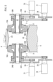
- the manufacturing apparatus includes a conveyor 5 (an example of a first conveying device), a cutter 1, an anvil roll 2, a turn drum D, a speed change roller 3 and a conveying roller 4 (an example of a second conveying device).
- a conveyor 5 an example of a first conveying device
- a cutter 1 an anvil roll 2, a turn drum D
- a speed change roller 3 an example of a second conveying device.
- the conveyor 5 conveys the continuous laminated body S at an introduction speed V1 while adsorbing a part of the continuous laminated body S continuous in the conveying direction Y (FIG. 1B) by the suction unit 50.
- the speed means the transport speed of the work (the object to be processed) and the peripheral speed of the surface of each roll or pad.
- the anvil roll 2 downstream of the conveyor 5 is rotating at a drum speed V2 greater than the introduction speed V1 of the conveyor 5.
- the anvil roll 2 sucks the front end portion S1 of the continuous laminated body S with the peripheral surface 2f while adsorbing the front end portion S1 of the continuous laminated body S with respect to the peripheral surface 2f.
- the conveyor 5 is conveyed at the introduction speed V1.
- the anvil roll 2 sucks the leading end S1 of the continuous laminated body S by the holding vacuum 2b and at the same time, has a constant speed larger than the introduction speed V1 at which the continuous laminated body S is supplied from the conveyor 5 to the anvil roll 2. It is rotating at drum speed V2.
- the leading end S1 of the continuous laminate S introduced into the anvil roll 2 at the introduction speed V1 is continuous with the continuous laminate and slips on the circumferential surface 2f of the anvil roll 2. Therefore, when the continuous laminated body S is introduced into the anvil roll 2, the speed at which the continuous laminated body S is transported on the anvil roll 2 is the introduction speed V1 of the conveyor 5.
- the cutter 1 cuts the tip portions S1 introduced onto the anvil roll 2 of the continuous laminate S continuous in the transport direction Y one after another at a predetermined interval in the transport direction Y to successively form a plurality of absorbent main bodies 20 one after another. Generate to That is, after cutting the leading end of the continuous laminate introduced onto the anvil roll 2 to generate the preceding absorbent main body 20, the leading end of the continuous laminate newly introduced onto the anvil roll 2 is cut The subsequent absorbent body 20 is produced.
- the anvil roll 2 carries out the continuous lamination by conveying the absorbent main body 20 (FIG. 1B) generated by cutting the tip portion S1 of the continuous laminated body S at the drum speed V2 along the circumferential surface 2f.
- the absorbent main body 20 is separated from the body S in the transport direction Y.
- the leading end portion S1 is released from the continuous laminated body S by cutting so that the same leading end portion S1 (absorbent main body 20) is conveyed at the drum speed V2 of the anvil roll 2,
- the distance to the tip S1 before cutting is increased.
- the distance between the continuous laminated body S conveyed on the anvil roll at the introduction speed V1 and the tip S1 after cutting conveyed at the drum speed V2 larger than the introduction speed V1 increases.
- the anvil roll 2 is provided with a holding vacuum 2b.
- the holding vacuum 2 b holds the tip portion S 1 of the continuous laminated body S before being cut by the separating cutter 1 on the anvil roll 2.
- the absorbent main body 20 obtained by cutting the tip end portion S1 with the cutter 1 is kept held by the anvil roll 2 until it is delivered to the holding pad P of the turn drum D.
- it is a well-known structure, it has a vacuum area for sucking the continuous laminate S or the absorbent main body 20 in a predetermined area of the anvil roll 2 by the holding vacuum 2b.
- the turn drum D downstream of the anvil roll 2 receives the separate absorbent main body 20 from the anvil roll 2.
- the drum speed V2 of the turn drum D and the drum speed V2 of the anvil roll 2 are set to the same speed.
- the turn drum D includes a plurality of holding pads P.
- the holding pad P receives the absorbent main body 20 from the anvil roll 2 and pivots around the normal L of the turn drum D to change the posture of the received absorbent main body 20.
- the turn drum D sequentially receives the respective absorbent main bodies 20 from the anvil roll 2 with a plurality of holding pads P. Thereafter, while the turn drum D transports the absorbent main body 20 at the constant drum speed V2, the holding pad P turns 90 ° around the normal line L of the turn drum D. As a result, the posture of the absorbent main body 20 along with the holding pad P is changed by 90 °.
- the absorbent main body 20 is passed from the turn drum D to the downstream speed change roller 4 after the posture change.
- the holding pad P may be provided with a suction device (not shown).
- the suction device sucks the absorbent main body 20 by vacuum from, for example, a large number of suction holes opened in the surface of the pad.
- the turn drum D is provided with a pivoting mechanism 6 for independently pivoting the holding pads P on the turn drum D, as is well known.
- the swing mechanism 6 may be configured by, for example, a cam groove 61 and a cam follower 62 formed on the peripheral surface of the fixed drum 60 of the turn drum D.
- Each of the holding pads P is pivotally supported on the rotating drum 63 around a normal line L.
- the rotating drum 63 is rotatably supported around the fixed drum 60 about an axis DL.
- the cam groove 61 is colored in gray.
- the transport roller 4 of FIG. 2 disposed downstream of the speed change roller 3 receiving the absorbent main body 20 from the turn drum D has a disposition speed V3 and transports the exterior material 21.
- the speed change roller 3 is disposed between the conveyance roller 4 and the turn drum D.
- the speed change roller 3 receives the absorbent main body 20 from the holding pad P of the turn drum D to the speed change pad 30 (30A, 30B) at the receiving position R1. Thereafter, the shift pads 30A and 30B arrange the absorbent main body 20 at the transfer position R2 on the exterior material 21 conveyed by the conveyance roller 4.
- the transmission roller 3 receives the absorbent main body 20 from the turn drum D at the receiving position R1 where the transmission pad 30 contacts the holding pad P via the absorbent main body 20. Thereafter, at the passing position R2 where the shift pad 30 contacts the transport roller 4 via the absorbent main body 20, the shift pad 30 is a wearable article transported by the transport roller 4 (an example of the transport device). It arrange
- the longitudinal direction of the sheathing material 21 is along the transport direction Y, and the transport direction Y is continuous with each other.
- the conveyance roller 4 may be a conveyance conveyor.
- the arrangement speed V3 of the conveyance roller 4 may be set to be smaller than the drum speed V2 of the turn drum D.
- the transmission roller 3 has, for example, two (plural) transmission pads 30 and a pair of servomotors 31 connected to the respective pads 30.
- the servomotor 31 performs the transfer position from the reception position R1. In the section up to R2, the speed of each pad 30 of the transmission roller 3 may be reduced from the drum speed V2 of the turn drum D to the arrangement speed V3 of the transport roller 4.
- the main body 20 is disposed from the pad 30 of the speed change roller 3 on the exterior material 21 conveyed by the conveyance roller 4. That is, at the receiving position R1, each pad 30 of the transmission roller 3 receives the absorbent main body 20 from the turn drum D at the drum speed V2. Thereafter, each pad 30 is decelerated to the arrangement speed V3 until it is rotated to the transfer position R2. Each pad 30 arranges the main body 20 on the exterior material 21 on the conveyance roller 4 at the arrangement speed V3 at the transfer position R2. After the placement, the respective pads 30 rotate to the receiving position R1 while increasing the speed to the drum speed V2.
- the transmission roller 3 of FIG. 4A is provided with a single long support shaft 32 in the axial direction.
- a pair of shift pads 30 rotate around the support shaft 32.
- First and second bearing portions 35 and 36 are supported at each end of the support shaft 32 via bearings 34 in each of the shift pads 30.
- the pair of shift pads 30 can rotate around the support shaft 32 without being constrained to each other.
- the shift pad 30 extending along the support shaft 32 is connected to the first bearing portion 35.
- the surface of the pad 30 in the longitudinal direction may be concave toward the support shaft 32. In this case, it will be easy to follow the shape of the arc-shaped holding pad P of the turn drum D and the like. Further, as shown in FIG. 4B, the side surface of the pad 30 may be, for example, an arc shape.
- the servomotors 31 are connected to the bearings 35 via gears 38, respectively. Therefore, each pad 30 is accelerated or decelerated as the rotational speed of the servomotor 31 changes.
- a control device 39 controls the rotation of both the servomotors 31, 31.
- the control device 39 includes a storage device for storing the relationship between the phase (rotational position) of the pad 30 with respect to the reference point (for example, the receiving position R1) and the rotational speed of the servomotor 31 and the peripheral speed of the pad 30.
- the storage device in addition to the standard size (M size) described later, the relationship is stored for each L size and / or XL size.
- the pair of pads 30, 30 periodically shift as the servomotors 31 (FIG. 4A) decelerate at least once per one rotation of the pad 30, and accelerate once. That is, the velocity of the pad 30 is the same as the drum velocity V2 of the turn drum D at the receiving position R1 (FIG. 2) where the pad 30 contacts the turn drum D and in the vicinity thereof. On the other hand, the velocity of the pad 30 is the same as the arrangement velocity V3 of the transport roller 4 at the transfer position R2 (FIG. 2) where the pad 30 contacts the transport roller 4 and its vicinity.
- the arrangement speed V3 is set to a speed lower than the drum speed V2.
- the pad 30 rotates while decelerating at a speed between the drum speed V2 and the arrangement speed V3. This reduces the distance between the leading absorbent body 20 and the trailing absorbent body 20, as is known.
- the pad 30 makes one revolution from the receiving position R1 to return to the receiving position R1
- the pad 30 has the same speed as the drum speed V2 of the turn drum D near the receiving position R1 and Thereafter, the speed is reduced to a speed smaller than the drum speed V2, and when entering a section near the transfer position R2, the speed is reduced to the same speed as the arrangement speed V3 of the transport roller 4.
- the pad 30 passes the section near the passing position R2; It is accelerated to a speed greater than the arrangement speed V3 of 4. Thereafter, when it enters a section near the receiving position R1, it further accelerates to the drum speed V2 of the turn drum D.
- the pad 30 accelerated to the drum speed V2 receives the absorbent main body 20 from the turn drum D, which is also rotating at the drum speed V2, at the receiving position R1. Note that the illustration of the absorbent main body 20 is omitted in FIGS. 4B to 4D.
- the present manufacturing method includes an introduction step, a slip step, a cutting step, a separation step, a first delivery step, a posture change step, a second delivery step, a speed change step, a transfer step, and a placement step described below.
- the continuous laminated body S which becomes the absorbent main body 20 continuously in the transport direction Y (FIG. 1B) is introduced from the conveyor 5 to the anvil roll 2 at an introduction speed V1 (V11).
- V1 introduction speed
- the front end portion S1 of the continuous laminated body S is adsorbed by the holding vacuum 2b on the circumferential surface 2f of the anvil roll 2 rotated at a drum speed V2 larger than the introduction speed V1.
- the continuous laminated body S is conveyed at the introduction speed V1 while causing the end portion S1 of the continuous laminated body S to slip on the circumferential surface 2f of the anvil roll 2.
- the front end portion S1 of the continuous laminated body S introduced at the introduction speed V1 on the anvil roll 2 is successively cut by the cutter 1 to obtain the absorbent main body 20 one after another.
- the absorbent main body 20 is transported at the drum speed V2 along the circumferential surface 2f of the anvil roll 2 to transfer the absorbent main body 20 from the continuous laminate S in the transporting direction.
- the leading end portion S1 of the cut continuous laminated body S is released from the continuous laminated body S by cutting, and conveyed at the drum speed V2 larger than the introduction speed V1. Therefore, the distance between the cut tip S1 (the absorbent main body 20) and the subsequent tip S1 of the continuous laminated body S before being conveyed at the introduction speed V1 is expanded.
- the separated absorbent main bodies 20 are sequentially transferred from the anvil roll 2 to the holding pads P of the turn drum D. That is, the absorbent main body 20 conveyed at the drum speed V2 in the anvil roll 2 is passed to the holding pad P of the turn drum D which also rotates at the drum speed V2.
- each holding pad P of the turn drum D that has received the absorbent main body 20 has a constant drum speed V2 around the axis line DL (FIG. 3B) of the turn drum D.
- the respective holding pads P turn around 90 ° around the normal L of the turn drum D on the turn drum D while rotating. By the turning, the postures of the respective absorbent main bodies 20 along with the respective holding pads P are changed.
- the drum speed is transferred from the holding pads P of the turn drum D to the speed change pads 30A and 30B of the speed change roller 3 in the absorptive main body 20 whose attitude is changed at the receiving position R1.
- the speed change roller 3 shifts from the drum speed V2 to the disposition speed V3 until the delivery position R1 reaches the delivery position R2. That is, after the speed change pad 30 of the speed change roller 3 receives the absorbent main body 20 at the drum speed V2 at the receiving position R1, the arrangement is slower than the drum speed V2 until reaching the transfer position R2. Reduce to speed V3.
- the transport device 4 transports the exterior material 21 at the arrangement speed V3 (V31).
- the absorbent main body 20 is placed one after another on the packaging material 21 transported by the transport device 4 at the transfer position R2. That is, the shift pads 30 of the transmission roller 3 that has been decelerated from the drum speed V2 to the arrangement speed V3 absorb the external material 21 conveyed at the arrangement speed V3 at the transfer position R2.
- the sex main bodies 20 are arranged one after another.
- the introduction speed V1 and the arrangement speed V3 are each set to a speed according to the size of the wearing article. Further, the introduction speed V1 may be larger than the arrangement speed V3. On the other hand, the drum speed V2 of the turn drum D is set to a constant speed regardless of the size.
- the drum speed V2 is set to a constant speed larger than the introduction speed V1 and the arrangement speed V3 regardless of the size of the worn article.
- L size for example, L size
- the introduction speed V1 is set to the high speed first introduction speed V11, and the arrangement speed V3 is set to the high speed first arrangement speed V31.
- the introduction speed V1 is set to the second introduction speed V12 lower than the first introduction speed V11.
- the arrangement speed V3 is set to a second arrangement speed V32 which is lower than the first arrangement speed V31.
- the drum speed V2 is set to a constant speed regardless of the size difference.
- the pitch (interval) P1 (FIG. 1B) of the absorbent main body 20 on the turn drum D adjacent to each other in the circumferential direction regardless of the size is also It remains constant.
- the length Ly (FIG. 1B) of the absorbent body 20 in the transport direction Y also decreases.
- the distance Dy (FIG. 6) between the rear end of the preceding absorbent body 20 of the second size wear article N2 and the front end of the subsequent absorbent body 20 corresponds to that of the first size wear article N1. It becomes larger than the distance Dy.
- the pitch P1 of the absorbent main body 20 on the turn drum D remains constant. Therefore, it is necessary to make small the pitch (interval) of the absorptive main body 20 arrange
- the distance Dx between the rear end of the preceding absorbent main body 20 and the front end of the subsequent absorbent main body 20 after posture change becomes smaller (the pitch becomes smaller).
- the second conveyance device 4 is set to the second arrangement speed V32.
- the second shift pad 30 receives the absorbent main body 20 at the receiving position R1 at the drum speed V2 and has a second arrangement speed lower than the first arrangement speed V31.
- the absorbent main body 20 is disposed on the sheathing material 21 at a velocity V32. Therefore, in the production of the second size wear article, the distance Dx between the absorbent main bodies is narrower than the distance Dx between the preceding and subsequent absorbent main bodies 20 in the production of the first size wear article. It will be arranged. This makes it possible to cope with size change.
- the introduction speed V1 is set to a third introduction speed V13, which is lower than the second introduction speed V12.
- the arrangement speed V3 is set to a third arrangement speed V33, which is lower than the second arrangement speed V32.
- the drum speed V2 is set to a constant speed regardless of the size.
- the pitch (interval) P1 of the absorbent main body 20 on the turn drum D also remains constant regardless of the size.
- the length Ly (FIG. 1B) of the absorbent main body 20 in the transport direction also decreases.
- the distance Dy between the trailing end of the leading absorbent body 20 and the leading end of the trailing absorbent body 20 is further increased.
- the pitch of the absorbent body 20 on the turn drum D remains constant. Therefore, it is necessary to further reduce the pitch (interval) of the absorbent main body 20 disposed on the exterior material 21 of FIG. 7. Therefore, in the case of the production of the third size wear article of FIG. 7, the deceleration of the shift pad 30 from the receiving position R1 to the delivery position R2 is larger than in the production of the second size wear article. The distance Dx between the rear end of the later leading absorbent body 20 and the front end of the following absorbent body 20 after posture change is further reduced (the pitch is further reduced). In manufacture of the wearing article of the third size, the second conveyance device 4 is set to the third arrangement speed V33.
- the shift pad 30 receives the absorbent main body 20 at the receiving position R1 at the drum speed V2 and a third arrangement having a speed smaller than the second arrangement speed V12.
- the absorbent main body 20 is disposed on the sheathing material 21 at a velocity V33. Therefore, in the production of the third size wear article, the distance Dx between the absorbent main bodies is narrower than the distance Dx between the preceding and subsequent absorbent main bodies 20 in the production of the second size wear article. Be placed.
- the speed change roller 3 holds a pair of first speed change pads 30A holding both longitudinal ends of the absorbent main body 20, and another longitudinal end of the absorbent main body 20. And a pair of second shift pads 30B. That is, one of the pair of first (second) shift pads 30A (30B) holds one end of the absorbent main body, and the other pad of the pair of shift pads is the same absorbent main body Hold the other end of the
- each shift pad 30A, 30B may be rotated by the servomotor 31 via the gear 38 and the timing belt T, respectively.
- the transmission pad 30B may be disposed around the support shaft 32, and the transmission pad 30A may be disposed around the transmission pad 30B.
- the diameters of the pulley portions of the speed change pads 30A and 30B may be the same.
- Each pad of the pair of shift pads 30A (30B) holding the both ends of the absorbent main body 20 rotates around the support shaft 32, and the above-mentioned exterior material 21 transported to the second transport device 4 is The absorbent body 20 is placed.
- Each pad may be provided with a suction device (not shown). The suction device sucks the end of the absorbent main body 20 by vacuum from, for example, a large number of suction holes opened on the surface of each pad.
- the present invention can be used for an apparatus for manufacturing an absorbent core of a disposable wearing article.
- Speed change pad 31 Servo motor 32: Support shaft 34: Bearing 35: First bearing portion 36: Second bearing portion 38: Gear 39: Control device 4: Second conveying device (conveying roller) 5: first conveying device (conveyor) 50: suction unit 6: turning mechanism 60: fixed drum 61: cam groove 62: cam follower 63: rotating drum D: turn drum Dy: distance Dx: distance P: holding pad R1: receiving position R2: delivery position V1: introduction speed V2: drum speed V3: arrangement speed S: continuous laminated body S1: tip L: Normal DL: Axis Y: Transport direction
Landscapes
- Health & Medical Sciences (AREA)
- Engineering & Computer Science (AREA)
- Life Sciences & Earth Sciences (AREA)
- Epidemiology (AREA)
- General Health & Medical Sciences (AREA)
- Biomedical Technology (AREA)
- Heart & Thoracic Surgery (AREA)
- Vascular Medicine (AREA)
- Veterinary Medicine (AREA)
- Animal Behavior & Ethology (AREA)
- Manufacturing & Machinery (AREA)
- Public Health (AREA)
- Mechanical Engineering (AREA)
- Forests & Forestry (AREA)
- Botany (AREA)
- Absorbent Articles And Supports Therefor (AREA)
- Details Of Cutting Devices (AREA)
Abstract
L'invention concerne, lors de la fabrication d'articles vestimentaires (N1) d'une première taille, le réglage de la vitesse d'introduction (V1) sur une première vitesse d'introduction (V11) élevée et le réglage de la vitesse d'agencement (V3) sur une première vitesse d'agencement (V31) élevée ; lors de la fabrication d'articles vestimentaires (N2) d'une seconde taille ayant une longueur dans la direction de transport plus courte que celle de la première taille, la vitesse d'introduction (V1) est réglée sur une seconde vitesse d'introduction (V12) inférieure à la première vitesse d'introduction (V11), la vitesse d'agencement (V3) est réglée à une seconde vitesse d'agencement (V32) inférieure à la première vitesse d'agencement (V31) et la vitesse de tambour (V2) est réglée à une vitesse constante, indépendamment de la taille.
Priority Applications (6)
| Application Number | Priority Date | Filing Date | Title |
|---|---|---|---|
| EP19740760.4A EP3741337B1 (fr) | 2018-01-16 | 2019-01-08 | Procédé de fabrication et dispositif de fabrication d'article vestimentaire jetable |
| KR1020207017736A KR102647220B1 (ko) | 2018-01-16 | 2019-01-08 | 일회용 착용 물품의 제조 방법 및 제조 장치 |
| CN201980007221.2A CN111587100B (zh) | 2018-01-16 | 2019-01-08 | 一次性穿着物品的制造方法及制造装置 |
| MX2020005721A MX2020005721A (es) | 2018-01-16 | 2019-01-08 | Metodo y aparato de fabricacion para articulo usable desechable. |
| US16/957,126 US11311425B2 (en) | 2018-01-16 | 2019-01-08 | Manufacturing method and manufacturing apparatus for disposable wearable article |
| JP2019566423A JP7311432B2 (ja) | 2018-01-16 | 2019-01-08 | 使い捨て着用物品の製造方法および製造装置 |
Applications Claiming Priority (2)
| Application Number | Priority Date | Filing Date | Title |
|---|---|---|---|
| JP2018004844 | 2018-01-16 | ||
| JP2018-004844 | 2018-01-16 |
Publications (1)
| Publication Number | Publication Date |
|---|---|
| WO2019142691A1 true WO2019142691A1 (fr) | 2019-07-25 |
Family
ID=67301785
Family Applications (1)
| Application Number | Title | Priority Date | Filing Date |
|---|---|---|---|
| PCT/JP2019/000180 Ceased WO2019142691A1 (fr) | 2018-01-16 | 2019-01-08 | Procédé de fabrication et dispositif de fabrication d'article vestimentaire jetable |
Country Status (7)
| Country | Link |
|---|---|
| US (1) | US11311425B2 (fr) |
| EP (1) | EP3741337B1 (fr) |
| JP (1) | JP7311432B2 (fr) |
| KR (1) | KR102647220B1 (fr) |
| CN (1) | CN111587100B (fr) |
| MX (1) | MX2020005721A (fr) |
| WO (1) | WO2019142691A1 (fr) |
Cited By (1)
| Publication number | Priority date | Publication date | Assignee | Title |
|---|---|---|---|---|
| WO2023218888A1 (fr) * | 2022-05-13 | 2023-11-16 | 株式会社瑞光 | Procédé et dispositif de fabrication d'un article portable jetable |
Families Citing this family (3)
| Publication number | Priority date | Publication date | Assignee | Title |
|---|---|---|---|---|
| DE102020104275A1 (de) * | 2020-02-18 | 2021-08-19 | Bicma Hygiene Technologie Gmbh | Drehvorrichtung für eine Fertigungsanlage für Hygieneprodukte |
| CN112026260A (zh) * | 2020-09-11 | 2020-12-04 | 福建省满利红包装彩印有限公司 | 一种耐高温彩印包装袋加工设备及其加工工艺 |
| EP4215321B1 (fr) * | 2022-01-25 | 2024-12-18 | The Procter & Gamble Company | Appareil et procédé de découpe d'un substrat |
Citations (7)
| Publication number | Priority date | Publication date | Assignee | Title |
|---|---|---|---|---|
| JP2003199790A (ja) * | 2001-11-02 | 2003-07-15 | Zuiko Corp | 使い捨て着用物品の製造方法 |
| WO2005075163A1 (fr) | 2004-02-05 | 2005-08-18 | Zuiko Corporation | Dispositif de traitement d'une bande et procede de traitement de bande |
| JP2007260875A (ja) | 2006-03-29 | 2007-10-11 | Kao Corp | シート切断方法及び装置 |
| JP2008035872A (ja) * | 2006-08-01 | 2008-02-21 | Zuiko Corp | 使い捨て着用物品の製造方法 |
| WO2013157533A1 (fr) * | 2012-04-19 | 2013-10-24 | 株式会社瑞光 | Procédé et dispositif de production d'article jetable pouvant être porté |
| JP2013255624A (ja) * | 2012-06-12 | 2013-12-26 | Zuiko Corp | 使い捨て着用物品の製造方法および製造装置 |
| WO2014006834A1 (fr) | 2012-07-06 | 2014-01-09 | 株式会社瑞光 | Procédé de transport, procédé de fabrication d'un article portable jetable, article jetable, et dispositif de transport |
Family Cites Families (4)
| Publication number | Priority date | Publication date | Assignee | Title |
|---|---|---|---|---|
| JP4094452B2 (ja) * | 2003-02-19 | 2008-06-04 | 株式会社瑞光 | 加工装置および加工方法 |
| JP2016536092A (ja) * | 2013-09-23 | 2016-11-24 | ザ プロクター アンド ギャンブル カンパニー | 吸収性物品上にサイドシームを作製するための装置及び方法 |
| US10391000B2 (en) * | 2015-05-28 | 2019-08-27 | Zuiko Corporation | Transport device and disposable wearable article production method using same |
| WO2017064763A1 (fr) * | 2015-10-14 | 2017-04-20 | ユニ・チャーム株式会社 | Procédé de transport et dispositif de transport de feuille découpée pour article absorbant |
-
2019
- 2019-01-08 US US16/957,126 patent/US11311425B2/en active Active
- 2019-01-08 JP JP2019566423A patent/JP7311432B2/ja active Active
- 2019-01-08 MX MX2020005721A patent/MX2020005721A/es unknown
- 2019-01-08 EP EP19740760.4A patent/EP3741337B1/fr active Active
- 2019-01-08 CN CN201980007221.2A patent/CN111587100B/zh active Active
- 2019-01-08 KR KR1020207017736A patent/KR102647220B1/ko active Active
- 2019-01-08 WO PCT/JP2019/000180 patent/WO2019142691A1/fr not_active Ceased
Patent Citations (7)
| Publication number | Priority date | Publication date | Assignee | Title |
|---|---|---|---|---|
| JP2003199790A (ja) * | 2001-11-02 | 2003-07-15 | Zuiko Corp | 使い捨て着用物品の製造方法 |
| WO2005075163A1 (fr) | 2004-02-05 | 2005-08-18 | Zuiko Corporation | Dispositif de traitement d'une bande et procede de traitement de bande |
| JP2007260875A (ja) | 2006-03-29 | 2007-10-11 | Kao Corp | シート切断方法及び装置 |
| JP2008035872A (ja) * | 2006-08-01 | 2008-02-21 | Zuiko Corp | 使い捨て着用物品の製造方法 |
| WO2013157533A1 (fr) * | 2012-04-19 | 2013-10-24 | 株式会社瑞光 | Procédé et dispositif de production d'article jetable pouvant être porté |
| JP2013255624A (ja) * | 2012-06-12 | 2013-12-26 | Zuiko Corp | 使い捨て着用物品の製造方法および製造装置 |
| WO2014006834A1 (fr) | 2012-07-06 | 2014-01-09 | 株式会社瑞光 | Procédé de transport, procédé de fabrication d'un article portable jetable, article jetable, et dispositif de transport |
Non-Patent Citations (1)
| Title |
|---|
| See also references of EP3741337A4 |
Cited By (3)
| Publication number | Priority date | Publication date | Assignee | Title |
|---|---|---|---|---|
| WO2023218888A1 (fr) * | 2022-05-13 | 2023-11-16 | 株式会社瑞光 | Procédé et dispositif de fabrication d'un article portable jetable |
| JPWO2023218888A1 (fr) * | 2022-05-13 | 2023-11-16 | ||
| EP4494619A4 (fr) * | 2022-05-13 | 2025-07-16 | Zuiko Corp | Procédé et dispositif de fabrication d'un article portable jetable |
Also Published As
| Publication number | Publication date |
|---|---|
| EP3741337C0 (fr) | 2025-03-05 |
| CN111587100A (zh) | 2020-08-25 |
| CN111587100B (zh) | 2022-03-18 |
| JP7311432B2 (ja) | 2023-07-19 |
| EP3741337A1 (fr) | 2020-11-25 |
| KR102647220B1 (ko) | 2024-03-14 |
| US11311425B2 (en) | 2022-04-26 |
| US20200345559A1 (en) | 2020-11-05 |
| EP3741337B1 (fr) | 2025-03-05 |
| MX2020005721A (es) | 2020-08-13 |
| JPWO2019142691A1 (ja) | 2021-01-28 |
| EP3741337A4 (fr) | 2021-12-15 |
| KR20200110309A (ko) | 2020-09-23 |
Similar Documents
| Publication | Publication Date | Title |
|---|---|---|
| WO2019142691A1 (fr) | Procédé de fabrication et dispositif de fabrication d'article vestimentaire jetable | |
| KR101614049B1 (ko) | 기저귀 반제품을 접기 위한 장치 및 방법 | |
| US8790232B2 (en) | Machine for making absorbent items | |
| JP4592201B2 (ja) | 搬送装置 | |
| JP6008599B2 (ja) | 使い捨て着用物品の製造方法 | |
| JPWO2001044086A1 (ja) | 搬送方法及び搬送装置 | |
| JP7216115B2 (ja) | 吸収性物品の製造装置および製造方法 | |
| WO2001044086A1 (fr) | Procede et dispositif de transport | |
| CN103781716B (zh) | 制造吸水性卫生用品的机器 | |
| JPWO2005085108A1 (ja) | ウエブ変速装置 | |
| JP5508034B2 (ja) | 切断装置 | |
| KR102461716B1 (ko) | 흡수성 물품의 제조장치 및 제조방법 | |
| EP2919733B1 (fr) | Procédé et machine de fabrication d'articles hygiéniques absorbants | |
| JP2008044796A (ja) | 搬送装置 | |
| JP2006230438A (ja) | 着用物品の製造方法および製造装置 | |
| WO2021171963A1 (fr) | Dispositif de transport de matériau en feuille et système de fabrication d'article à porter jetable équipé dudit dispositif de transport | |
| WO2022270233A1 (fr) | Procédé et dispositif pour la fabrication d'article à porter | |
| WO2023002819A1 (fr) | Procédé et dispositif pour la fabrication d'article à porter | |
| WO2017137865A1 (fr) | Procédé et machine de fabrication d'articles hygiéniques absorbants | |
| WO2023037938A1 (fr) | Dispositif et procédé de fabrication d'un article pouvant être porté jetable |
Legal Events
| Date | Code | Title | Description |
|---|---|---|---|
| 121 | Ep: the epo has been informed by wipo that ep was designated in this application |
Ref document number: 19740760 Country of ref document: EP Kind code of ref document: A1 |
|
| ENP | Entry into the national phase |
Ref document number: 2019566423 Country of ref document: JP Kind code of ref document: A |
|
| NENP | Non-entry into the national phase |
Ref country code: DE |
|
| ENP | Entry into the national phase |
Ref document number: 2019740760 Country of ref document: EP Effective date: 20200817 |