WO2019142841A1 - Câble à fibre optique - Google Patents
Câble à fibre optique Download PDFInfo
- Publication number
- WO2019142841A1 WO2019142841A1 PCT/JP2019/001173 JP2019001173W WO2019142841A1 WO 2019142841 A1 WO2019142841 A1 WO 2019142841A1 JP 2019001173 W JP2019001173 W JP 2019001173W WO 2019142841 A1 WO2019142841 A1 WO 2019142841A1
- Authority
- WO
- WIPO (PCT)
- Prior art keywords
- optical fiber
- slot
- core
- cable
- tube
- Prior art date
- Legal status (The legal status is an assumption and is not a legal conclusion. Google has not performed a legal analysis and makes no representation as to the accuracy of the status listed.)
- Ceased
Links
Images


Classifications
-
- G—PHYSICS
- G02—OPTICS
- G02B—OPTICAL ELEMENTS, SYSTEMS OR APPARATUS
- G02B6/00—Light guides; Structural details of arrangements comprising light guides and other optical elements, e.g. couplings
- G02B6/44—Mechanical structures for providing tensile strength and external protection for fibres, e.g. optical transmission cables
- G02B6/4401—Optical cables
- G02B6/4407—Optical cables with internal fluted support member
-
- G—PHYSICS
- G02—OPTICS
- G02B—OPTICAL ELEMENTS, SYSTEMS OR APPARATUS
- G02B6/00—Light guides; Structural details of arrangements comprising light guides and other optical elements, e.g. couplings
- G02B6/44—Mechanical structures for providing tensile strength and external protection for fibres, e.g. optical transmission cables
- G02B6/4401—Optical cables
- G02B6/4405—Optical cables with longitudinally spaced waveguide clamping
-
- G—PHYSICS
- G02—OPTICS
- G02B—OPTICAL ELEMENTS, SYSTEMS OR APPARATUS
- G02B6/00—Light guides; Structural details of arrangements comprising light guides and other optical elements, e.g. couplings
- G02B6/44—Mechanical structures for providing tensile strength and external protection for fibres, e.g. optical transmission cables
- G02B6/4401—Optical cables
- G02B6/4407—Optical cables with internal fluted support member
- G02B6/4409—Optical cables with internal fluted support member for ribbons
-
- G—PHYSICS
- G02—OPTICS
- G02B—OPTICAL ELEMENTS, SYSTEMS OR APPARATUS
- G02B6/00—Light guides; Structural details of arrangements comprising light guides and other optical elements, e.g. couplings
- G02B6/44—Mechanical structures for providing tensile strength and external protection for fibres, e.g. optical transmission cables
- G02B6/4401—Optical cables
- G02B6/4403—Optical cables with ribbon structure
- G02B6/4404—Multi-podded
Definitions
- the present disclosure relates to fiber optic cables.
- This application claims priority based on Japanese Patent Application No. 2018-006300 filed on Jan. 18, 2018, and incorporates the entire contents described in the aforementioned Japanese application.
- Patent Document 1 describes an optical fiber cable including an optical fiber ribbon in a pipe.
- Patent Document 2 describes an optical fiber unit in which a plurality of optical fiber cores are bundled.
- Patent Document 3 a slot core in which a slot groove for housing an optical fiber is formed on the outer peripheral surface along the cable longitudinal direction, and a press-winding tape wound around the entire outer peripheral surface of the slot core so as to cover the slot groove;
- a fiber optic cable is described having a press-winding tape and a sheath covering the slotted core.
- the optical fiber cable according to one aspect of the present disclosure is An optical fiber cable comprising: a plurality of ribs formed along the longitudinal direction of the cable; and a slot core having a slot groove for accommodating an optical fiber between the ribs. Between some or all of the optical fibers, a connecting portion in which adjacent optical fibers are connected and an unconnected portion in which adjacent optical fibers are not connected are intermittently interrupted.
- a subunit formed by bundling a plurality of intermittently coupled optical fiber ribbons A thin tube having a lower Young's modulus than the material forming the slot core, Have The subunit is housed in the slot groove, Among the subunits in the slot groove, at least the subunit located on the outer periphery of the slot groove is covered by the tube.
- a winding such as coarse winding or a water absorption tape is applied around the outer periphery of the slot groove.
- this winding is wound on the slot core under tension, the cable is deformed into a polygonal shape so that the space for the optical fiber to be inside the straight line connecting the rib apexes of the slots. For this reason, the space which can accommodate an optical fiber core line is restricted. This is a limitation in increasing the number of cores and increasing the density of the optical fiber cable.
- the present disclosure is directed to providing a multicore, high density fiber optic cable.
- the optical fiber cable according to one aspect of the present disclosure is (1) An optical fiber cable comprising: a plurality of ribs formed along the longitudinal direction of the cable; and a slot core having a slot groove for accommodating an optical fiber between the ribs, Between some or all of the optical fibers, a connecting portion in which adjacent optical fibers are connected and an unconnected portion in which adjacent optical fibers are not connected are intermittently interrupted.
- a subunit formed by bundling a plurality of intermittently coupled optical fiber ribbons A thin tube having a lower Young's modulus than the material forming the slot core, Have The subunit is housed in the slot groove, Among the subunits in the slot groove, at least the subunit located on the outer periphery of the slot groove is covered by the tube. According to the above configuration, since the sub-units located on the outer periphery of the slot groove are covered with the thin-skinned tube having a Young's modulus lower than that of the material forming the slot core, coarse winding or water absorption is performed on the outer periphery of the slot groove. It is not necessary to hold back the tape or the like. For this reason, since there is no deformation of the cable due to rough winding or press-winding, there is no restriction of the optical fiber accommodation space due to this deformation, and it is possible to provide a multi-core high density optical fiber cable.
- the number of optical fibers accommodated in one slot groove may be 288 or more. According to the above configuration, it is possible to provide a multi-core optical fiber cable in which the number of optical fibers accommodated in one slot groove is 288 or more.
- h be the length of the root portion of the rib defined by the line connecting the bottom portions of the slot grooves, and the distance between the root portion and the apex of the rib by a straight line be the rib height h
- h / t may be 4 or more and 8 or less. According to the above configuration, by making h / t 4 or more, the rib becomes thin, and more optical fibers can be accommodated in the slot groove. In addition, since h / t is 8 or less, the strength of the rib can be secured to some extent, and the rib is not easily deformed.
- At least the outermost layer portion of the slot core may be formed of an engineering plastic. According to the above configuration, since at least the outermost layer portion of the slot core is formed of an engineering plastic which is a relatively hard material, the strength of the slot core can be increased.
- the water absorption yarn may be provided in the tube. According to the above configuration, since the water absorbing yarn is contained in the tube, the tube can be provided with a waterproof function.
- the core density of the optical fiber housed in the optical fiber cable may be 5.0 cores / mm 2 or more. According to the above configuration, it is possible to provide a high-density optical fiber cable having a core density of 5.0 cores / mm 2 or more.
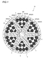
- FIG. 1 is a cross-sectional view perpendicular to the longitudinal direction of the optical fiber cable according to the first embodiment of the present disclosure.
- the optical fiber cable 1A of the first embodiment includes a slot core 4 having a plurality of (six in this example) ribs 2 and a slot groove 3 provided between the ribs 2 Slot type cable.
- the rib 2 and the slot groove 3 are formed, for example, in a spiral or SZ shape along the longitudinal direction (longitudinal direction) of the optical fiber cable 1A.
- subunits 20 formed by bundling a plurality of optical fiber ribbons 10 are accommodated along the longitudinal direction of the optical fiber cable 1A.
- seven sub-units 20 (20A to 20G) are accommodated in one slot groove 3, for example.
- 18 optical fiber ribbons 10 are bundled in one subunit.
- the eighteen optical fiber ribbons 10 constituting each of the subunits 20A to 20G are twisted together and assembled.
- Each of the subunits 20A to 20G may be wound with, for example, a bundle material (not shown) so that the twisted optical fiber ribbons 10 do not break apart.
- the bundle material may be a distinctive colored bundle material.
- the seven subunits 20 (20A to 20G) may be spirally wound with, for example, a roughly wound yarn (not shown) so as to form one assembly.
- the whole of the seven subunits 20A to 20G housed in each slot groove 3 is covered with a thin tube 30A on the outer periphery.
- the thickness of the tube 30A is about 0.3 mm.
- the tube 30A is made of, for example, a plastic resin such as low density polyethylene (PE) or polyvinyl chloride (PVC).
- the Young's modulus of the resin forming the tube 30A is lower than, for example, the Young's modulus of the material forming the slot core 4.
- the tube 30A can be easily elastically deformed. The material of the slot core 4 will be described later.
- an opening may be formed, for example, by interrupting a part in the circumferential direction, in order to facilitate removal of the internal subunits 20A to 20G.
- the opening is formed, for example, in a spiral shape along the longitudinal direction of the subunit 20.
- a water absorbing yarn 40 having a waterproof function may be provided in the tube 30A.
- the water absorbing yarn 40 is, for example, a linear member having an outer diameter of about 0.1 mm in a dry state, and is provided along the longitudinal direction of the optical fiber cable 1A.
- a jacket 5 is provided on the outer periphery of the slot core 4 so as to cover the slot groove 3.
- the jacket 5 is formed of, for example, a resin such as polyethylene (PE).
- PE polyethylene
- the jacket 5 is formed around the slot core 4 by extruding a resin.
- the jacket 5 is provided in direct contact with a tube 30A that covers the subunits 20A to 20G.
- a tension member 6 formed of a steel wire or the like is embedded along the longitudinal direction of the optical fiber cable 1A.
- the slot core 4 has a two-layer structure having a first layer portion 7 provided on the outer periphery of the tension member 6 and a second layer portion 8 (an example of the outermost layer portion) provided on the outer periphery of the first layer portion 7. It is formed.
- the first layer portion 7 is provided as an adhesive layer for bonding the tension member 6 and the second layer portion 8.
- the first layer portion 7 is formed of, for example, a resin having a relatively low Young's modulus, such as an ethylene-methacrylic acid copolymer.
- the second layer portion 8 is a layer forming a portion outside the first layer portion 7, and the rib 2 is also included in the second layer portion 8.
- the second layer portion 8 is formed of, for example, an engineering plastic having a relatively high Young's modulus, such as polybutylene terephthalate (PBT).
- PBT polybutylene terephthalate
- the number of ribs 2 constituting the slot core 4 be small, that is, the number of slot grooves 3 be small. Therefore, in the optical fiber cable 1A, the number of slot grooves 3 in the slot core 4 is set to six or less.
- the volume occupied by the ribs 2 in the slot core 4 be small, that is, the thickness (thickness) of each rib 2 be thin (thin). Therefore, in the optical fiber cable 1A, as shown in FIG. 1, the length of the root portion of the rib 2 defined by the line connecting the bottom portions of adjacent slot grooves 3 is t, and the apex of the rib 2 from the root portion When the distance h connecting the straight lines is a height h of the rib 2, h / t is set to 4 or more and 8 or less.
- the bottom of the slot groove 3 means the bottom point B closest to the center point X of the slot core 4 in the slot groove 3 having a round bottom as shown in FIG.
- the ribs 2 become thinner, and more optical fibers can be accommodated in the slot groove 3.
- the strength of the rib can be secured to some extent, and the rib is not easily deformed.
- the second layer portion 8 of the slot core 4 is formed of an engineering plastic having a high Young's modulus.
- FIG. 2 shows an example of the optical fiber ribbon cable 10 constituting the subunit 20.
- the optical fiber ribbons 10 are adjacent to each other at a connecting portion 12 in which adjacent optical fibers are connected with a plurality of optical fibers 11A to 11L being arranged in parallel.
- the optical fiber ribbon is an intermittent connection type optical fiber in which unconnected portions 13 where the optical fibers are not connected are intermittently provided in the longitudinal direction.
- FIG. 2 shows an intermittent connection type optical fiber ribbon in a state where the optical fibers 11A to 11L are opened in the arrangement direction.
- the location where the connection part 12 and the non-connection part 13 are intermittently provided may be between some optical fiber cores as shown in FIG. 2 or between all the optical fiber cores It may be.
- the non-connecting portion 13 is not provided between the optical fiber cores 11A and 11B, 11C and 11D, 11E and 11F, 11G and 11H, 11I and 11J, and 11K and 11L.
- connection portion 12 in the optical fiber ribbon 10 is formed by applying a connection resin 14 made of, for example, an ultraviolet curable resin, a thermosetting resin, or the like between the optical fibers.
- the connection resin 14 is intermittently applied between predetermined optical fiber cores, so that the connection part 12 and the non-connection part 13 are intermittently provided, and the optical fiber cores 11A to 11L are in parallel.
- the connecting resin 14 may be applied to only one side of the parallel surface formed by the parallel optical fiber cores 11A to 11L, or may be applied to both sides. Also, for example, after applying the tape resin to one side or all the both sides of the optical fiber ribbons 11A to 11L arranged in parallel, the optical fiber ribbons 10 are connected to all the optical fiber ribbons 11A to 11L.
- a part may be cut with a rotary blade or the like to form the non-connecting portion 13.
- the optical fibers 11A to 11L are composed of, for example, a glass fiber composed of a core and a clad, and a covering layer for covering the glass fiber.
- the coating layers of the optical fiber cores 11A to 11L are colored, for example, in different colors so that the optical fiber cores can be distinguished.
- the outer diameter of the optical fibers 11A to 11L is preferably 0.2 mm or less. If it is a small diameter fiber with an outer diameter of 0.2 mm or less, high density can be achieved.
- the number of optical fiber cores accommodated in one slot groove 3 is preferably 288 or more, and the core density of the optical fiber cores accommodated in the optical fiber cable 1A is 5. It is preferable that it is 0 core / mm 2 or more.
- an optical fiber tape of 12 cores is provided with six subunits 20 in each of which 18 optical fiber tapes 10 are collected in the slot groove 3.
- One subunit 20 in which twelve core wires 10 are gathered is accommodated.
- the total number of optical fiber cores is 1440 (12 ⁇ 18 ⁇ 6 + 12 ⁇ 12 ⁇ 1).
- the total number of optical fiber cores accommodated in the optical fiber cable 1A is 8640 (1440 ⁇ 6). Since the outer diameter of the optical fiber cable 1A is 37 mm, its cross-sectional area is 1075 mm 2 . Therefore, the core density of the optical fiber in the optical fiber cable 1A is 8.0 cores / mm 2 (8640/1075), and is 5.0 cores / mm 2 or more.
- the outer periphery of the slot core 104 is provided with a press winding 130 such as rough winding or a water absorption tape so as to cover the slot groove 103.
- the slot core 104 has the same structure as the slot core 4 of the first embodiment.
- the press-fit winding 130 is wound by applying tension to the outer periphery of the slot core 104, so that it has a polygonal shape connecting the apexes of the ribs 102. For this reason, the space 140 between the jacket 105 having a circular cross section and the holding winding 130 having a polygonal shape can not be used as a housing space for the optical fiber 110.
- the external shape of the slot type cable 100 becomes a polygonal shape without the space 140 of FIG. Therefore, in the slot type cable 100 of the comparative example, the space which can accommodate the optical fiber 110 in the slot groove 103 is inside the line connecting the apexes of the ribs 102 (the pressure winding 130). This is a limitation in increasing the number of optical fibers 110 and increasing the density.
- the entire subunits 20A to 20G accommodated in the slot groove 3 are covered with the thin tube 30A. Therefore, the sub-units 20A to 20G accommodated in the slot groove 3 and the optical fiber ribbons 10 constituting the sub-units 20A to 20G do not break apart and pop out of the slot groove 3, so the outer periphery of the slot groove 3 It is not necessary to apply a press wrap to Therefore, the restriction of the accommodation space of the slot groove 3 by applying the press-winding is eliminated, and the accommodation space of the slot groove 3 can be utilized effectively without waste. As a result, a large number of optical fiber ribbons 10 can be accommodated in the slot groove 3, and a multi-core high density optical fiber cable can be provided.
- the tube covering the subunits 20A to 20G corresponding to the shape of the accommodation space of the slot groove 3 30A is elastically deformable. Therefore, the storage space of the slot groove 3 can be utilized without waste.
- the second layer portion 8 which is the outermost layer portion of the slot core 4 is formed of an engineering plastic which is a relatively hard material, the strength of the slot core 4 can be increased. Therefore, the ratio h / t of the height h of the rib 2 to the length t of the root portion of the rib 2 can be set to 4 or more, and the rib 2 can be made thinner. Can be accommodated.
- the tube 30A can be provided with a waterproof function.
- Second Embodiment A fiber optic cable according to a second embodiment of the present disclosure will be described with reference to FIG.
- symbol is attached
- FIG. 3 is a cross-sectional view perpendicular to the longitudinal direction of the optical fiber cable 1B according to the second embodiment.
- the optical fiber cable 1B is the first point that the subunit 20 located on the outer peripheral portion of the slot groove 3 (position in contact with the jacket 5) is covered by a tube.
- the optical fiber of the first embodiment is the same as the embodiment but in that the entire subunits 20A to 20G are covered in that only the subunit 20 located on the outer peripheral part of the slot groove 3 is covered by the tube 30B. It differs from cable 1A.
- the subunits 20A to 20D located on the outer peripheral part of the slot groove 3 are covered with the tube 30B. Furthermore, in this example, among the subunits 20A to 20D located on the outer peripheral part of the slot groove 3, the subunits 20A and 20B are covered with one tube 30B, and the subunits 20C and 20D are covered with another tube 30B. There is. Since the subunits 20A to 20G accommodated in the slot groove 3 are not twisted together, the subunits 20A to 20D covered with the tube 30B must be always located (present) on the outer peripheral part of the slot groove 3 It will be.
- the number of subunits 20 covered with the tube 30B may be single or plural.
- each of the subunits 20A to 20D may be covered with the tube 30B, or four subunits 20A to 20D may be covered with one tube 30B. Also, it may be divided into one subunit 20 and three subunits 20 and covered with separate tubes 30B.
- the optical fiber cable 1B of the second embodiment at least the subunits 20A to 20D located on the outer peripheral portion of the slot groove 3 are covered with the thin tube 30B. Therefore, the optical fiber ribbons 10 constituting the sub-units 20A to 20D and the sub-units 20A to 20D accommodated in the outer peripheral portion of the slot groove 3 do not separate and pop out of the slot groove 3. Further, since the subunits 20A to 20D covered with the tube 30B are disposed on the outer peripheral part, the subunits 20E to 20G accommodated inside the slot groove 3 and the optical fiber ribbon 10 constituting the same are also provided. It does not pop out of the slot groove 3. Therefore, since the outer periphery of the slot groove 3 does not have to be wound around, the restriction of the accommodation space of the slot groove 3 is eliminated as in the first embodiment, and a multi-core high-density optical fiber cable is provided. Can.
- 1A, 1B optical fiber cable 2: rib 3: slot groove 4: slot core 5: jacket 7: first layer portion 8: second layer portion (an example of the outermost layer portion) 10: Optical fiber tape core 11A-11L: Optical fiber core 12: Connection part 13: Non connection part 20 (20A-20G): Sub unit 30A, 30B: Tube 40: Water absorption yarn
Landscapes
- Physics & Mathematics (AREA)
- General Physics & Mathematics (AREA)
- Optics & Photonics (AREA)
- Optical Fibers, Optical Fiber Cores, And Optical Fiber Bundles (AREA)
- Light Guides In General And Applications Therefor (AREA)
- Mechanical Coupling Of Light Guides (AREA)
Abstract
Cette invention concerne un câble à fibre optique ayant une pluralité de nervures formées le long de la direction longitudinale du câble, et ayant une âme fendue dans laquelle des rainures de fente pour recevoir des rubans de fibre optique sont formées entre les nervures, le câble à fibre optique comprenant : des sous-unités regroupant une pluralité de rubans de fibre optique de type à connexion intermittente, des parties connectées dans lesquelles des âmes de fibres optiques adjacentes sont connectées et des parties non connectées dans lesquelles âmes de fibres optiques adjacentes ne sont pas connectées, disposées de façon intermittente dans la direction longitudinale entre une partie ou la totalité des âmes de fibre optique dans les rubans de fibre optique de type à connexion intermittente ; et un tube de type chemise mince ayant un module de Young inférieur à celui d'un matériau utilisé pour former l'âme fendue. Les sous-unités sont logées dans les rainures de fente, et, parmi les sous-unités dans les rainures de fente, au moins les sous-unités positionnées dans la périphérie externe des rainures de fente étant recouvertes par le tube.
Priority Applications (3)
| Application Number | Priority Date | Filing Date | Title |
|---|---|---|---|
| EP19741726.4A EP3742212B1 (fr) | 2018-01-18 | 2019-01-17 | Câble à fibre optique |
| JP2019566491A JP7151727B2 (ja) | 2018-01-18 | 2019-01-17 | 光ファイバケーブル |
| US16/962,053 US10914906B2 (en) | 2018-01-18 | 2019-01-17 | Optical fiber cable |
Applications Claiming Priority (2)
| Application Number | Priority Date | Filing Date | Title |
|---|---|---|---|
| JP2018-006300 | 2018-01-18 | ||
| JP2018006300 | 2018-01-18 |
Publications (1)
| Publication Number | Publication Date |
|---|---|
| WO2019142841A1 true WO2019142841A1 (fr) | 2019-07-25 |
Family
ID=67302291
Family Applications (1)
| Application Number | Title | Priority Date | Filing Date |
|---|---|---|---|
| PCT/JP2019/001173 Ceased WO2019142841A1 (fr) | 2018-01-18 | 2019-01-17 | Câble à fibre optique |
Country Status (4)
| Country | Link |
|---|---|
| US (1) | US10914906B2 (fr) |
| EP (1) | EP3742212B1 (fr) |
| JP (1) | JP7151727B2 (fr) |
| WO (1) | WO2019142841A1 (fr) |
Cited By (6)
| Publication number | Priority date | Publication date | Assignee | Title |
|---|---|---|---|---|
| JPWO2022065485A1 (fr) * | 2020-09-28 | 2022-03-31 | ||
| US20220326467A1 (en) * | 2019-09-11 | 2022-10-13 | Sumitomo Electric Industries, Ltd. | Optical fiber unit and optical fiber cable |
| JPWO2023105748A1 (fr) * | 2021-12-10 | 2023-06-15 | ||
| WO2023113012A1 (fr) * | 2021-12-17 | 2023-06-22 | 住友電気工業株式会社 | Câble à fibres optiques |
| JP2023167346A (ja) * | 2022-05-11 | 2023-11-24 | 住友電気工業株式会社 | 光ケーブル用スロット及び光ケーブル |
| US20240353639A1 (en) * | 2021-12-10 | 2024-10-24 | Sumitomo Electric Industries, Ltd. | Optical fiber cable and method for manufacturing optical fiber cable |
Citations (10)
| Publication number | Priority date | Publication date | Assignee | Title |
|---|---|---|---|---|
| EP0996016A2 (fr) * | 1998-10-23 | 2000-04-26 | Bowthorpe Plc | Câble à fibres optiques |
| JP2003195129A (ja) * | 2001-12-25 | 2003-07-09 | Sumitomo Electric Ind Ltd | 光ファイバケーブル用スロット部材及び光ファイバケーブル |
| JP2010008923A (ja) | 2008-06-30 | 2010-01-14 | Nippon Telegr & Teleph Corp <Ntt> | 光ファイバケーブル |
| JP2014071441A (ja) | 2012-10-02 | 2014-04-21 | Fujikura Ltd | 光ファイバケーブル |
| JP2015099314A (ja) * | 2013-11-20 | 2015-05-28 | 株式会社フジクラ | スロット型光ファイバケーブル |
| JP2015099315A (ja) * | 2013-11-20 | 2015-05-28 | 株式会社フジクラ | スロット型光ファイバケーブル |
| JP2015517679A (ja) | 2012-05-02 | 2015-06-22 | エーエフエル・テレコミュニケーションズ・エルエルシー | リボン型光ファイバー構造体を有する円形で小径の光ケーブル |
| JP2017134267A (ja) * | 2016-01-28 | 2017-08-03 | 住友電気工業株式会社 | 光ファイバケーブル |
| JP2017223730A (ja) * | 2016-06-13 | 2017-12-21 | 住友電気工業株式会社 | 光ファイバケーブル |
| JP2018006300A (ja) | 2016-07-08 | 2018-01-11 | 日産自動車株式会社 | 燃料電池用金属セパレータ及びこれを用いた燃料電池 |
Family Cites Families (17)
| Publication number | Priority date | Publication date | Assignee | Title |
|---|---|---|---|---|
| US4767484A (en) * | 1986-02-20 | 1988-08-30 | The United States Of America As Represented By The Administrator Of The National Aeronautics And Space Adminstration | Method of attaching strain gauges to various materials |
| US4814133A (en) * | 1986-07-24 | 1989-03-21 | Ube-Nitto Kasei Co., Ltd. | Method of forming the spacer of an optical fiber cable |
| DE3811126A1 (de) * | 1988-03-31 | 1989-10-12 | Siemens Ag | Optisches kabel mit mehreren buendelelementen |
| FR2665266B1 (fr) * | 1990-07-27 | 1993-07-30 | Silec Liaisons Elec | Cable de telecommunication a fibres optiques. |
| DE4408548A1 (de) * | 1994-03-14 | 1995-12-07 | Siemens Ag | Optisches Übertragungselement sowie optisches Kabel |
| JPH08262294A (ja) * | 1995-03-17 | 1996-10-11 | Fujikura Ltd | スロット型光ファイバケーブル |
| US5649043A (en) * | 1995-07-25 | 1997-07-15 | Alcatel Na Cable Systems, Inc. | Optical fiber cable having truncated triangular profile tubes |
| EP1146373B1 (fr) * | 1999-06-03 | 2007-05-16 | Ube-Nitto Kasei Co. Ltd. | Separateur pour cable a fibres optiques, procede de fabrication correspondant et cable a fibres optiques utilisant ce separateur |
| WO2010001663A1 (fr) | 2008-06-30 | 2010-01-07 | 日本電信電話株式会社 | Câble à fibres optiques et bande à fibres optiques |
| JP2011008923A (ja) | 2009-06-23 | 2011-01-13 | Canon Anelva Corp | 電界放出型電子放出素子の製造方法と製造装置、及び画像表示装置の製造方法 |
| US8805143B2 (en) * | 2009-10-19 | 2014-08-12 | Draka Comteq, B.V. | Optical-fiber cable having high fiber count and high fiber density |
| WO2015052951A1 (fr) * | 2013-10-07 | 2015-04-16 | 株式会社フジクラ | Unité de fibre optique, procédé de branchement de fibre optique et câble à fibres optiques |
| JP2016020990A (ja) * | 2014-07-15 | 2016-02-04 | 住友電気工業株式会社 | 光ケーブル用のスロットロッド及び光ケーブル |
| JP6679875B2 (ja) * | 2015-10-14 | 2020-04-15 | 住友電気工業株式会社 | 光ファイバケーブル用のスロットロッドおよび光ファイバケーブル |
| JP6708009B2 (ja) * | 2016-06-21 | 2020-06-10 | 住友電気工業株式会社 | 光ケーブル |
| JP7052727B2 (ja) * | 2016-12-06 | 2022-04-12 | 住友電気工業株式会社 | 間欠連結型光ファイバテープ心線、その製造方法、光ファイバケーブルおよび光ファイバコード |
| US10983294B2 (en) * | 2018-02-27 | 2021-04-20 | Optical Cable Corporation | Deployable fiber optic cable with partially bonded ribbon fibers |
-
2019
- 2019-01-17 WO PCT/JP2019/001173 patent/WO2019142841A1/fr not_active Ceased
- 2019-01-17 US US16/962,053 patent/US10914906B2/en active Active
- 2019-01-17 EP EP19741726.4A patent/EP3742212B1/fr active Active
- 2019-01-17 JP JP2019566491A patent/JP7151727B2/ja active Active
Patent Citations (10)
| Publication number | Priority date | Publication date | Assignee | Title |
|---|---|---|---|---|
| EP0996016A2 (fr) * | 1998-10-23 | 2000-04-26 | Bowthorpe Plc | Câble à fibres optiques |
| JP2003195129A (ja) * | 2001-12-25 | 2003-07-09 | Sumitomo Electric Ind Ltd | 光ファイバケーブル用スロット部材及び光ファイバケーブル |
| JP2010008923A (ja) | 2008-06-30 | 2010-01-14 | Nippon Telegr & Teleph Corp <Ntt> | 光ファイバケーブル |
| JP2015517679A (ja) | 2012-05-02 | 2015-06-22 | エーエフエル・テレコミュニケーションズ・エルエルシー | リボン型光ファイバー構造体を有する円形で小径の光ケーブル |
| JP2014071441A (ja) | 2012-10-02 | 2014-04-21 | Fujikura Ltd | 光ファイバケーブル |
| JP2015099314A (ja) * | 2013-11-20 | 2015-05-28 | 株式会社フジクラ | スロット型光ファイバケーブル |
| JP2015099315A (ja) * | 2013-11-20 | 2015-05-28 | 株式会社フジクラ | スロット型光ファイバケーブル |
| JP2017134267A (ja) * | 2016-01-28 | 2017-08-03 | 住友電気工業株式会社 | 光ファイバケーブル |
| JP2017223730A (ja) * | 2016-06-13 | 2017-12-21 | 住友電気工業株式会社 | 光ファイバケーブル |
| JP2018006300A (ja) | 2016-07-08 | 2018-01-11 | 日産自動車株式会社 | 燃料電池用金属セパレータ及びこれを用いた燃料電池 |
Cited By (12)
| Publication number | Priority date | Publication date | Assignee | Title |
|---|---|---|---|---|
| US20220326467A1 (en) * | 2019-09-11 | 2022-10-13 | Sumitomo Electric Industries, Ltd. | Optical fiber unit and optical fiber cable |
| EP4030211A4 (fr) * | 2019-09-11 | 2022-10-26 | Sumitomo Electric Industries, Ltd. | Unité de fibre optique et câble à fibres optiques |
| US11892700B2 (en) | 2019-09-11 | 2024-02-06 | Sumitomo Electric Industries, Ltd. | Optical fiber unit and optical fiber cable |
| JPWO2022065485A1 (fr) * | 2020-09-28 | 2022-03-31 | ||
| WO2022065485A1 (fr) * | 2020-09-28 | 2022-03-31 | 住友電気工業株式会社 | Câble à fibres optiques et câble avec connecteur |
| JPWO2023105748A1 (fr) * | 2021-12-10 | 2023-06-15 | ||
| WO2023105748A1 (fr) * | 2021-12-10 | 2023-06-15 | 住友電気工業株式会社 | Câble à fibres optiques et système de connexion de câble à fibres optiques |
| US20240353639A1 (en) * | 2021-12-10 | 2024-10-24 | Sumitomo Electric Industries, Ltd. | Optical fiber cable and method for manufacturing optical fiber cable |
| JP7743874B2 (ja) | 2021-12-10 | 2025-09-25 | 住友電気工業株式会社 | 光ファイバケーブルおよび光ファイバケーブル接続システム |
| WO2023113012A1 (fr) * | 2021-12-17 | 2023-06-22 | 住友電気工業株式会社 | Câble à fibres optiques |
| JP2023167346A (ja) * | 2022-05-11 | 2023-11-24 | 住友電気工業株式会社 | 光ケーブル用スロット及び光ケーブル |
| JP7800293B2 (ja) | 2022-05-11 | 2026-01-16 | 住友電気工業株式会社 | 光ケーブル用スロット及び光ケーブル |
Also Published As
| Publication number | Publication date |
|---|---|
| JP7151727B2 (ja) | 2022-10-12 |
| US20200409005A1 (en) | 2020-12-31 |
| EP3742212B1 (fr) | 2023-08-16 |
| EP3742212A1 (fr) | 2020-11-25 |
| US10914906B2 (en) | 2021-02-09 |
| JPWO2019142841A1 (ja) | 2021-01-07 |
| EP3742212A4 (fr) | 2021-09-15 |
Similar Documents
| Publication | Publication Date | Title |
|---|---|---|
| JP7151727B2 (ja) | 光ファイバケーブル | |
| WO2017131117A1 (fr) | Câble à fibres optiques | |
| CN109642999B (zh) | 光纤缆线 | |
| JP6958361B2 (ja) | 光ファイバケーブル | |
| JP7192782B2 (ja) | 光ファイバユニットおよび光ファイバケーブル | |
| KR20080027328A (ko) | 광섬유 케이블 및 그 제조방법 | |
| JP7120248B2 (ja) | 光ファイバユニットおよび光ファイバケーブル | |
| US12510716B2 (en) | Optical fiber cable and cable with connector | |
| JP2011100115A (ja) | 光ファイバケーブル | |
| JP2020024257A (ja) | 光ファイバテープ心線、光ファイバケーブル、および光ファイバテープ心線の融着接続方法 | |
| JP7200947B2 (ja) | 光ファイバケーブルおよび光ファイバケーブルの製造方法 | |
| JP5158893B2 (ja) | 光ファイバユニット及び光ファイバケーブル | |
| US6529662B1 (en) | Optical fiber cable | |
| JP6459833B2 (ja) | 光ファイバケーブル | |
| WO2022065485A1 (fr) | Câble à fibres optiques et câble avec connecteur | |
| JP6413593B2 (ja) | 光ファイバケーブル | |
| JP2019056837A (ja) | 光ファイバケーブル | |
| JP2015018053A (ja) | 光ケーブル | |
| JP2016177138A (ja) | 光ケーブル | |
| JPH09197202A (ja) | 光ファイバケーブル | |
| WO2020246511A1 (fr) | Câble à fibre optique et procédé de fabrication de câble à fibre optique | |
| JP2022013026A (ja) | 光ケーブル | |
| JP2012088359A (ja) | 光ケーブル | |
| JP4624279B2 (ja) | 光ファイバケーブル | |
| JPH09197203A (ja) | 光ファイバケーブル |
Legal Events
| Date | Code | Title | Description |
|---|---|---|---|
| 121 | Ep: the epo has been informed by wipo that ep was designated in this application |
Ref document number: 19741726 Country of ref document: EP Kind code of ref document: A1 |
|
| ENP | Entry into the national phase |
Ref document number: 2019566491 Country of ref document: JP Kind code of ref document: A |
|
| NENP | Non-entry into the national phase |
Ref country code: DE |
|
| ENP | Entry into the national phase |
Ref document number: 2019741726 Country of ref document: EP Effective date: 20200818 |