WO2019146371A1 - 入力装置 - Google Patents
入力装置 Download PDFInfo
- Publication number
- WO2019146371A1 WO2019146371A1 PCT/JP2018/048207 JP2018048207W WO2019146371A1 WO 2019146371 A1 WO2019146371 A1 WO 2019146371A1 JP 2018048207 W JP2018048207 W JP 2018048207W WO 2019146371 A1 WO2019146371 A1 WO 2019146371A1
- Authority
- WO
- WIPO (PCT)
- Prior art keywords
- yoke
- coil
- torque
- magnetic
- brake
- Prior art date
- Legal status (The legal status is an assumption and is not a legal conclusion. Google has not performed a legal analysis and makes no representation as to the accuracy of the status listed.)
- Ceased
Links
Images





Classifications
-
- F—MECHANICAL ENGINEERING; LIGHTING; HEATING; WEAPONS; BLASTING
- F16—ENGINEERING ELEMENTS AND UNITS; GENERAL MEASURES FOR PRODUCING AND MAINTAINING EFFECTIVE FUNCTIONING OF MACHINES OR INSTALLATIONS; THERMAL INSULATION IN GENERAL
- F16D—COUPLINGS FOR TRANSMITTING ROTATION; CLUTCHES; BRAKES
- F16D63/00—Brakes not otherwise provided for; Brakes combining more than one of the types of groups F16D49/00 - F16D61/00
-
- F—MECHANICAL ENGINEERING; LIGHTING; HEATING; WEAPONS; BLASTING
- F16—ENGINEERING ELEMENTS AND UNITS; GENERAL MEASURES FOR PRODUCING AND MAINTAINING EFFECTIVE FUNCTIONING OF MACHINES OR INSTALLATIONS; THERMAL INSULATION IN GENERAL
- F16D—COUPLINGS FOR TRANSMITTING ROTATION; CLUTCHES; BRAKES
- F16D57/00—Liquid-resistance brakes; Brakes using the internal friction of fluids or fluid-like media, e.g. powders
- F16D57/002—Liquid-resistance brakes; Brakes using the internal friction of fluids or fluid-like media, e.g. powders comprising a medium with electrically or magnetically controlled internal friction, e.g. electrorheological fluid, magnetic powder
-
- F—MECHANICAL ENGINEERING; LIGHTING; HEATING; WEAPONS; BLASTING
- F16—ENGINEERING ELEMENTS AND UNITS; GENERAL MEASURES FOR PRODUCING AND MAINTAINING EFFECTIVE FUNCTIONING OF MACHINES OR INSTALLATIONS; THERMAL INSULATION IN GENERAL
- F16D—COUPLINGS FOR TRANSMITTING ROTATION; CLUTCHES; BRAKES
- F16D57/00—Liquid-resistance brakes; Brakes using the internal friction of fluids or fluid-like media, e.g. powders
- F16D57/007—Liquid-resistance brakes; Brakes using the internal friction of fluids or fluid-like media, e.g. powders with variable brake geometry, e.g. axially movable rotor or stator
-
- F—MECHANICAL ENGINEERING; LIGHTING; HEATING; WEAPONS; BLASTING
- F16—ENGINEERING ELEMENTS AND UNITS; GENERAL MEASURES FOR PRODUCING AND MAINTAINING EFFECTIVE FUNCTIONING OF MACHINES OR INSTALLATIONS; THERMAL INSULATION IN GENERAL
- F16F—SPRINGS; SHOCK-ABSORBERS; MEANS FOR DAMPING VIBRATION
- F16F9/00—Springs, vibration-dampers, shock-absorbers, or similarly-constructed movement-dampers using a fluid or the equivalent as damping medium
- F16F9/10—Springs, vibration-dampers, shock-absorbers, or similarly-constructed movement-dampers using a fluid or the equivalent as damping medium using liquid only; using a fluid of which the nature is immaterial
- F16F9/12—Devices with one or more rotary vanes turning in the fluid any throttling effect being immaterial, i.e. damping by viscous shear effect only
-
- F—MECHANICAL ENGINEERING; LIGHTING; HEATING; WEAPONS; BLASTING
- F16—ENGINEERING ELEMENTS AND UNITS; GENERAL MEASURES FOR PRODUCING AND MAINTAINING EFFECTIVE FUNCTIONING OF MACHINES OR INSTALLATIONS; THERMAL INSULATION IN GENERAL
- F16F—SPRINGS; SHOCK-ABSORBERS; MEANS FOR DAMPING VIBRATION
- F16F9/00—Springs, vibration-dampers, shock-absorbers, or similarly-constructed movement-dampers using a fluid or the equivalent as damping medium
- F16F9/32—Details
- F16F9/53—Means for adjusting damping characteristics by varying fluid viscosity, e.g. electromagnetically
-
- F—MECHANICAL ENGINEERING; LIGHTING; HEATING; WEAPONS; BLASTING
- F16—ENGINEERING ELEMENTS AND UNITS; GENERAL MEASURES FOR PRODUCING AND MAINTAINING EFFECTIVE FUNCTIONING OF MACHINES OR INSTALLATIONS; THERMAL INSULATION IN GENERAL
- F16F—SPRINGS; SHOCK-ABSORBERS; MEANS FOR DAMPING VIBRATION
- F16F9/00—Springs, vibration-dampers, shock-absorbers, or similarly-constructed movement-dampers using a fluid or the equivalent as damping medium
- F16F9/32—Details
- F16F9/53—Means for adjusting damping characteristics by varying fluid viscosity, e.g. electromagnetically
- F16F9/535—Magnetorheological [MR] fluid dampers
-
- G—PHYSICS
- G05—CONTROLLING; REGULATING
- G05G—CONTROL DEVICES OR SYSTEMS INSOFAR AS CHARACTERISED BY MECHANICAL FEATURES ONLY
- G05G1/00—Controlling members, e.g. knobs or handles; Assemblies or arrangements thereof; Indicating position of controlling members
- G05G1/08—Controlling members for hand actuation by rotary movement, e.g. hand wheels
- G05G1/10—Details, e.g. of discs, knobs, wheels or handles
-
- G—PHYSICS
- G05—CONTROLLING; REGULATING
- G05G—CONTROL DEVICES OR SYSTEMS INSOFAR AS CHARACTERISED BY MECHANICAL FEATURES ONLY
- G05G5/00—Means for preventing, limiting or returning the movements of parts of a control mechanism, e.g. locking controlling member
- G05G5/03—Means for enhancing the operator's awareness of arrival of the controlling member at a command or datum position; Providing feel, e.g. means for creating a counterforce
-
- H—ELECTRICITY
- H02—GENERATION; CONVERSION OR DISTRIBUTION OF ELECTRIC POWER
- H02K—DYNAMO-ELECTRIC MACHINES
- H02K21/00—Synchronous motors having permanent magnets; Synchronous generators having permanent magnets
- H02K21/12—Synchronous motors having permanent magnets; Synchronous generators having permanent magnets with stationary armatures and rotating magnets
- H02K21/14—Synchronous motors having permanent magnets; Synchronous generators having permanent magnets with stationary armatures and rotating magnets with magnets rotating within the armatures
-
- H—ELECTRICITY
- H02—GENERATION; CONVERSION OR DISTRIBUTION OF ELECTRIC POWER
- H02K—DYNAMO-ELECTRIC MACHINES
- H02K7/00—Arrangements for handling mechanical energy structurally associated with dynamo-electric machines, e.g. structural association with mechanical driving motors or auxiliary dynamo-electric machines
- H02K7/003—Couplings; Details of shafts
-
- H—ELECTRICITY
- H02—GENERATION; CONVERSION OR DISTRIBUTION OF ELECTRIC POWER
- H02K—DYNAMO-ELECTRIC MACHINES
- H02K7/00—Arrangements for handling mechanical energy structurally associated with dynamo-electric machines, e.g. structural association with mechanical driving motors or auxiliary dynamo-electric machines
- H02K7/10—Structural association with clutches, brakes, gears, pulleys or mechanical starters
- H02K7/102—Structural association with clutches, brakes, gears, pulleys or mechanical starters with friction brakes
-
- H—ELECTRICITY
- H02—GENERATION; CONVERSION OR DISTRIBUTION OF ELECTRIC POWER
- H02K—DYNAMO-ELECTRIC MACHINES
- H02K7/00—Arrangements for handling mechanical energy structurally associated with dynamo-electric machines, e.g. structural association with mechanical driving motors or auxiliary dynamo-electric machines
- H02K7/10—Structural association with clutches, brakes, gears, pulleys or mechanical starters
- H02K7/102—Structural association with clutches, brakes, gears, pulleys or mechanical starters with friction brakes
- H02K7/1021—Magnetically influenced friction brakes
- H02K7/1023—Magnetically influenced friction brakes using electromagnets
-
- F—MECHANICAL ENGINEERING; LIGHTING; HEATING; WEAPONS; BLASTING
- F16—ENGINEERING ELEMENTS AND UNITS; GENERAL MEASURES FOR PRODUCING AND MAINTAINING EFFECTIVE FUNCTIONING OF MACHINES OR INSTALLATIONS; THERMAL INSULATION IN GENERAL
- F16D—COUPLINGS FOR TRANSMITTING ROTATION; CLUTCHES; BRAKES
- F16D66/00—Arrangements for monitoring working conditions, e.g. wear, temperature
- F16D2066/003—Position, angle or speed
-
- G—PHYSICS
- G05—CONTROLLING; REGULATING
- G05G—CONTROL DEVICES OR SYSTEMS INSOFAR AS CHARACTERISED BY MECHANICAL FEATURES ONLY
- G05G1/00—Controlling members, e.g. knobs or handles; Assemblies or arrangements thereof; Indicating position of controlling members
- G05G1/08—Controlling members for hand actuation by rotary movement, e.g. hand wheels
-
- H—ELECTRICITY
- H02—GENERATION; CONVERSION OR DISTRIBUTION OF ELECTRIC POWER
- H02K—DYNAMO-ELECTRIC MACHINES
- H02K11/00—Structural association of dynamo-electric machines with electric components or with devices for shielding, monitoring or protection
- H02K11/20—Structural association of dynamo-electric machines with electric components or with devices for shielding, monitoring or protection for measuring, monitoring, testing, protecting or switching
- H02K11/24—Devices for sensing torque, or actuated thereby
-
- H—ELECTRICITY
- H02—GENERATION; CONVERSION OR DISTRIBUTION OF ELECTRIC POWER
- H02K—DYNAMO-ELECTRIC MACHINES
- H02K2201/00—Specific aspects not provided for in the other groups of this subclass relating to the magnetic circuits
- H02K2201/03—Machines characterised by aspects of the air-gap between rotor and stator
-
- H—ELECTRICITY
- H02—GENERATION; CONVERSION OR DISTRIBUTION OF ELECTRIC POWER
- H02K—DYNAMO-ELECTRIC MACHINES
- H02K2213/00—Specific aspects, not otherwise provided for and not covered by codes H02K2201/00 - H02K2211/00
- H02K2213/09—Machines characterised by the presence of elements which are subject to variation, e.g. adjustable bearings, reconfigurable windings, variable pitch ventilators
Definitions
- the present invention relates to an input device that can change the rotational resistance using a magnetorheological fluid.
- the operation feeling imparting type input device described in Patent Document 1 includes a rotary operation unit, an encoder for detecting the rotation state of the operation unit, an armature rotor that rotates with the operation unit, and the operation unit via the armature rotor. And an electric motor for applying a self-supporting rotational force to the operation unit through the rotation shaft, and a control unit for driving the electromagnetic brake and the electric motor.
- the control unit can drive the electromagnetic brake to suppress the consumption of power when applying a rotational resistance, and can drive the electric motor to rotate the operation unit in a self-supporting manner.
- the winding in the electromagnetic brake on the outside of the electric motor, it is aimed to shorten the body in the direction along the rotation axis as the whole device.
- an object of this invention is to provide the input device suitable for size reduction in the direction of the rotating shaft of a rotary body.
- the input device of the present invention is provided with a fixed portion, a rotating body supported so as to be rotatable around a rotating shaft, and a rotation detecting portion for detecting the rotation of the rotating body.
- the input device includes a brake applying unit that applies a braking force to the rotating body, and a torque applying unit that applies a driving torque of rotation around the rotation axis to the rotating body.
- the brake applying unit includes a rotating plate rotatably provided together with the rotating body, a magnetorheological fluid interposed in a gap between the fixed unit and the rotating plate, and a brake applying coil for applying a magnetic field to the magnetorheological fluid,
- the application unit has a stator and a rotor supported so as to be rotatable with respect to the stator.
- a magnet is applied to either one of the stator and the rotor, and at least two-phase torque is applied to the other.
- Koi A control unit for controlling the current supplied to the brake applying coil and the torque applying coil by a magnetic field induced by the torque applying coil, and providing a control unit for controlling the current applied to the brake applying coil and the torque applying coil; It is characterized in that it is arranged so as to surround the outer circumference of the.
- control unit can separately control the current supplied to the brake application coil and the current supplied to the torque application coil, and can simultaneously generate the braking force and the driving torque. . This makes it possible to give the operator various operating feels.
- the rotor is rotatably supported together with the rotating body, and is disposed on the outer periphery of the annular back yoke and the back yoke, and a plurality of the back yokes are arranged alternately with different polarities in the circumferential direction.
- the stator is disposed so as to surround the outer periphery in the radial direction of the rotor, and has a coil formed of a nonmagnetic coil as a torque applying coil, and a fixing member for fixing the coil. It is preferable to be disposed to face the permanent magnet.
- the core of the magnetic body has no convex pole and a coil having no convex pole is used, cogging torque is not generated even when the rotation operation is performed in a state where the coil is not energized. Therefore, it is possible to prevent the manipulation feeling from being deteriorated by the cogging torque. Furthermore, when the fixing member of the stator is made of a nonmagnetic material, not only cogging due to the strength of the magnetic attraction force but also rotation resistance due to the magnetic attraction force of the permanent magnet does not occur.
- the input device of the present invention eight torque applying coils are arranged, and an electric current is applied so that adjacent torque applying coils generate magnetic fields in opposite directions to each other, and the torque applying coils are adjacent as two A phases. It is preferable that current is simultaneously applied to one coil and two coils symmetrical with respect to the rotation axis, and current is simultaneously applied to the remaining four coils as B phase.
- the curvature of the torque applying portion can be suppressed to a low level, which facilitates manufacture.
- produces can increase the area which cross
- the brake applying unit includes a shaft that rotates with the rotary plate, and the shaft is preferably connected to the rotating body via a connecting member having a spring property.
- a connecting member having a spring property This makes it possible to cause a phase shift between the rotational operation of the shaft portion of the brake application unit and the rotational operation of the rotating body. For this reason, even when the shaft of the brake application portion is stopped in the end stop state, when a low torque is applied to the rotating body, the shaft is twisted with the rotation of the rotating body, so that the rotation
- the detection unit can detect the rotation of the rotating body, and when the end stop state is released based on the detection result, it is possible to give the operator an operation feeling with a small feeling of catching at that time.
- the torque applying coil and the brake applying coil are disposed such that the center lines are orthogonal to each other. Therefore, even if the torque applying coil and the brake applying coil are close to each other, the interference between the magnetic fields generated by each can be suppressed, and the magnetic field generated by the torque applying coil affects the magnetorheological fluid of the brake applying unit. It can be made smaller.
- miniaturization can be achieved in the direction of the rotation axis of the rotating body.
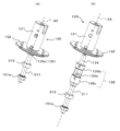
- (A), (b) is a perspective view showing composition of an input device concerning an embodiment of the present invention. It is a disassembled perspective view of the input device shown to FIG. 1 (a), (b). It is sectional drawing of the input device which concerns on embodiment of this invention containing the rotating shaft of a rotary body. It is a functional block diagram of an input device concerning an embodiment of the present invention.
- (A)-(d) is a top view which shows the relationship between the air core coil of a coil part, and the magnet of a magnet part in embodiment of this invention.
- (A) is the perspective view which looked at the brake application part from the upper side in embodiment of this invention
- (b) is the perspective view which looked at the brake application part from lower side.
- FIG. 11 is a cross-sectional view taken along the line IX-IX ′ of FIG. It is a partially enlarged view of FIG. (A) is a perspective view which shows the state in which the rotary body, the connection member, and the axial part were mutually connected in embodiment of this invention, (b) is the state which isolate
- FIG. It is a disassembled perspective view of a rotary body and a connection member in an embodiment of the present invention.
- FIGS. 1A and 1B are perspective views showing the configuration of an input device 110 according to an embodiment of the present invention.
- FIG. 2 is an exploded perspective view of the input device 110 shown in FIGS. 1 (a) and 1 (b).
- FIG. 3 is a cross-sectional view of the input device 110 including the rotation axis AX of the rotating body 130.
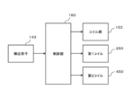
- FIG. 4 is a functional block diagram of the input device 110. As shown in FIG.
- the direction along the rotation axis AX which is the rotation center of the rotating body 130, is referred to as the vertical direction, and the direction orthogonal to the rotation axis AX is referred to as the radial direction.
- the vertical direction can be arbitrarily set in accordance with the attitude of the input device or the like.
- a state viewed along the direction of the rotation axis AX is referred to as a plan view, and a direction along the circumference of a circle centered on the rotation axis AX in a plan view is referred to as a circumferential direction.
- the input device 110 includes a fixing unit 120, a rotating body 130, a connection member 135, a rotation detecting unit 140, a torque applying unit 150, and a brake applying unit 210. As shown in FIGS. 1 (a) and 1 (b), they are assembled and used.
- the input device 110 further includes a control unit 160 shown in FIG.
- the fixing portion 120 is a plate made of a nonmagnetic material.
- an opening 121 penetrating vertically is provided at a central portion in a plan view.
- the shaft portion 311 of the brake application portion 210 extends outward through the opening 121 (see FIG. 1B).
- the torque applying unit 150 includes a base plate 151, a fixing member 152, a coil unit 153, a magnet unit 154, a back yoke 155, and a coil holder 156, and is substantially symmetrical with respect to the rotation axis AX. It is configured.
- the fixing member 152 made of a nonmagnetic material and the coil portion 153 fixed to the inner circumferential surface of the fixing member 152 constitute a stator.
- the magnet unit 154 disposed opposite to the inner peripheral surface of the coil unit 153 and the back yoke 155 fixed to the inner peripheral surface of the magnet unit 154 constitute a rotor. The rotor is supported to be rotatable with respect to the stator.
- the base plate 151 has a substantially disc shape, and is fixed on the fixing portion 120 so that the central axis thereof is positioned on the rotation axis AX. As shown in FIGS. 2 and 3, a cylindrical pretensioner 151 a is concentrically disposed at the center of the base plate 151. As shown in FIG. 3, the pretensioner 151 a is fixed by penetrating the fixing portion 120 and the base plate 151 up and down and supporting the shaft portion 310 inserted therein from the radial direction.
- the base plate 151 is provided with a positioning recess 151b as a coil holder for positioning and holding the lower portion of the air core coils 153a to 153h (described later) along the outer periphery thereof.
- the outer edge recessed part 151c dented below rather than the positioning recessed part 151b is provided in the outer side of the positioning recessed part 151b.
- the base plate 151 is configured approximately symmetrically with respect to the rotation axis AX.
- the lower part of the coil part 153 is inserted in the positioning recessed part 151b, and the coil part 153 is positioned by this.
- a plurality of conductive pins 122 are provided to penetrate the base plate 151 vertically.
- the pin 122 is exposed to the outside from the lower portion of the input device 110 through the opening 121 of the fixed portion 120, and the control portion 160 controls the coil portion 153 and the first coil 250 and the first coil 250 in the brake applying portion 210.
- a predetermined current is supplied to two coils 450.
- the lower portion of the cylindrical fixing member 152 is fitted to the outer edge recess 151 c of the base plate 151, whereby the fixing member 152 is positioned along the outer periphery of the base plate 151. 151 and the fixing unit 120 are fixed. Thereby, the fixing member 152 is configured substantially symmetrically with respect to the rotation axis AX.
- eight air core coils 153a, 153b, 153c, 153d, 153e, 153f, 153g, 153h as torque applying coils are provided on the inner peripheral surface of the fixing member 152. .
- the eight air core coils 153a to 153h constitute a coil portion 153.
- the eight air core coils 153a, 153b, 153c, 153d, 153e, 153f, 153g, and 153h are disposed along the circumferential direction with respect to the inner peripheral surface 152a (see FIG. 2) of the fixing member 152.
- the eight air core coils 153a to 153h are arranged at equal angular intervals on a circle centered on the rotation axis AX, and each of them is wound around a radial line extending from the rotation axis AX toward the circumference as a center line. It is Thus, the coil portion 153 is configured approximately symmetrically with respect to the rotation axis AX.
- a current controlled by the control unit 160 is applied to each of the air core coils 153a to 153h (see FIG. 4).
- the magnet unit 154 includes six magnets 154a, 154b, 154c, 154d, 154e, 154f.
- the magnets 154a to 154f are disposed inside the air core coils 153a to 153h so as to face the air core coils 153a to 153h of the coil portion 153 with a predetermined gap in the radial direction.
- the magnets 154a to 154f are arranged along the circumferential direction with respect to the outer peripheral surface 155a of the cylindrical back yoke 155.
- magnets 154a to 154f are arranged at equal angular intervals on a circle centered on the rotation axis AX, and the magnetic poles are arranged along the radial direction from the rotation axis AX toward the circumference.
- the arrangement of the magnetic poles is set so that adjacent magnetic poles are in opposite directions to each other.
- the magnet unit 154 and the back yoke 155 are respectively configured substantially symmetrically with respect to the rotation axis AX.
- FIGS. 5 (a) to 5 (d) only the outer magnetic pole is shown for simplification, and for example, in the magnet 154a, the outer side is the south pole and the inner side near the rotation axis AX is the north pole. .
- FIGS. 5 (a) to 5 (d) are plan views showing the relationship between the air-cored coils 153a to 153h of the coil portion 153 and the magnets 154a to 154f of the magnet portion 154.
- FIG. FIGS. 5 (a) to 5 (d) show positions where the magnets 154a to 154f are stabilized when the energization of the air core coils 153a to 153h is switched, that is, positions where the maximum torque is generated.
- the direction of the current in the vertical direction (direction along the rotation axis AX) when the current is applied to the air-cored coils 153a to 153h is shown. It means the upper side of the paper.
- the eight air core coils 153a to 153h have their upper and lower positions determined and held by the coil holder 156 and the base plate 151, respectively.
- the coil holder 156 has a ring shape, and is fixed along the upper end of the outer peripheral surface of the fixing member 152 so that the central axis is placed on the rotation axis AX.
- the coil holder 156 is configured substantially symmetrically with respect to the rotation axis AX.
- the base plate 151, the fixing member 152, the coil portion 153, the magnet portion 154, the back yoke 155, and the coil holder 156 are configured substantially symmetrically with respect to the rotation axis AX, torque is applied.
- the part 150 is configured substantially symmetrically with respect to the rotation axis AX as a whole.
- the application of current to the air core coils 153a to 153h is performed at two adjacent air core coils and at a position symmetrical with respect to the rotation axis AX with respect to these two air core coils. It is performed on a total of four coils (one set of coils) with two adjacent coils.
- a pair of adjacent two air-cored coils 153b and 153c and two air-cored coils 153f and 153g which are symmetrical with respect to the rotation axis AX A state in which current is applied is referred to as A phase
- another set of coils in which current is not applied in phase A that is, two adjacent air core coils A state in which current is applied to 153 h and 153 a and two air-cored coils 153 d and 153 e that are symmetrical with respect to the rotation axis AX with respect to them is referred to as a B phase.
- four coils forming a set are connected in series. That is, four air core coils 153b, 153c, 153f and 153g corresponding to the A phase are connected in series, and four air core coils 153h, 153a, 153d and 153e corresponding to the B phase are also connected in series.
- the energization of the air core coils 153a to 153h is controlled so as to switch the two phases of the A phase and the B phase each time the rotating body 130 rotates 120 degrees, and the drawing of FIG.
- the states shown in 5 (a) to (d) are switched three times every 120 degrees.
- the coil portion 153 fixed to the base plate 151, the fixing member 152, and the fixing portion 120 by applying a current to each of the air core coils 153a to 153h in the four patterns shown in FIGS. 5 (a) to 5 (d).
- the magnet unit 154 can be relatively rotated or rotated around the rotation axis AX, and the back yoke 155 to which the magnet unit 154 is fixed is also rotated or rotated.
- a rotating body 130 described below is concentrically fixed to the back yoke 155, and a driving torque for rotation or rotation is transmitted to the rotating body 130 as the magnet unit 154 rotates or turns.
- FIG. 6A is a perspective view of the brake applying unit 210 as viewed from above
- FIG. 6B is a perspective view of the brake applying unit 210 as viewed from below
- 7 and 8 are exploded perspective views of the brake applying unit 210 as viewed from the upper side.
- FIG. 7 is a perspective view of the upper portion 210A on the upper side up to the A portion
- FIG. 8 is a perspective view of the lower portion 210B on the lower side from the A portion.
- FIG. 9 is a cross-sectional view taken along the line IX-IX ′ of FIG. 6A and conceptually shows the magnetic field generated by the two coils 250 and 450.
- FIG. 10 is a partially enlarged view of FIG.
- a direction parallel to the central axis 211 is taken as a first direction D1 (FIG. 6, FIG. 9), and a radial direction orthogonal to the central axis 211 is taken as a second direction D2 (FIG. 6, FIG. 9) It is called.
- the state which looked at the lower side from the upper side along the central axis 211 may be called planar view.
- FIGS. 7 and 8 the display of some screws and the magnetorheological fluid is omitted.
- the brake applying unit 210 includes a holding unit 220 and a rotational operation unit 300, and is configured substantially symmetrically with respect to the central axis 211.
- the rotation operation unit 300 includes a shaft portion 310 and two magnetic disks 320 and 520 (rotating plates), and is integrally coupled so as to rotate in both directions around a central axis 211 (rotation axis). .
- torque application unit 150 is arranged to surround the outer circumference of brake application unit 210.
- the central axis 211 of the brake applying unit 210 is disposed on the rotation axis AX of the rotating body 130, and the bottom surface of the third yoke 490 of the brake applying unit 210 is fixed to the base plate 151.
- the first direction D1 is along the direction of the rotation axis AX
- the second direction D2 is orthogonal to the direction of the rotation axis AX.
- the rotational operation unit 300 is rotatably supported by the holding unit 220 via the two radial bearings 351 and 551 and the two pushers 352 and 552 (see FIGS. 7 and 8). Furthermore, as shown in FIG. 10, in the two gaps 280 and 480 provided in the brake application unit 210, the magnetorheological fluid 360 and 560 is filled and filled.
- the holding unit 220 is, in the upper portion 210A shown in FIG. 7, the first yoke 230, the second yoke 240, the first coil 250 as a brake applying coil, the sealing member 260, and the upper portion It includes the third yoke 290 as a case.
- the first yoke 230 is positioned on one side of the magnetic disk 320
- the second yoke 240 is positioned on the other side of the magnetic disk 320.
- first yoke 230, the second yoke 240, the first coil 250, the sealing member 260, and the third yoke 290 are configured approximately symmetrically with respect to the central axis 211 (rotation axis).
- the upper portion 210A of the holding portion 220 is configured substantially symmetrically with respect to the central axis 211 (rotation axis) as a whole.
- a lower portion 210B shown in FIG. 8 includes a first yoke 430, a second yoke 440, a second coil 450 as a brake applying coil, a sealing member 460, and a third yoke 490 as a lower case.
- the first yoke 430 is positioned on one side of the magnetic disk 520
- the second yoke 440 is positioned on the other side of the magnetic disk 520.
- the first yoke 430, the second yoke 440, the second coil 450, the sealing member 460, and the third yoke 490 are configured approximately symmetrically with respect to the central axis 211 (rotational axis).
- the lower portion 210B of the holding portion 220 is configured substantially symmetrically with respect to the central axis 211 (rotation axis) as a whole.
- the retaining portion 220 includes an annular member 270 that spans the upper portion 210A and the lower portion 210B.
- the first yoke 230, the second yoke 240, and the third yoke 290 are separately processed and formed, and in the lower portion 210B, the first yoke 430, the second yoke 440, and the second The three yokes 490 are separately processed and formed.
- any of these yokes may be combined and integrally formed.
- the first coil 250 of the upper portion 210A has an annular shape as shown in FIG.
- the first coil 250 is a coil including a conducting wire wound around the central axis 211.
- the second coil 450 of the lower portion 210B has an annular shape as shown in FIG.
- the second coil 450 is also a coil including a conducting wire wound around the central axis 211.
- Connecting members (not shown) are electrically connected to the two coils 250 and 450, respectively, and current is supplied from the control unit 160 through a path not shown. By supplying the current, a magnetic field is generated in each of the coils 250 and 450.
- the first yoke 230 of the upper portion 210A includes an inner yoke 231 as an inner peripheral member and an outer yoke 232 as an outer peripheral member.
- the inner yoke 231 and the outer yoke 232 are arranged concentrically about the central axis 211.
- the first yoke 430 of the lower portion 210B includes an inner yoke 431 as an inner peripheral side member and an outer yoke 432 as an outer peripheral side member.
- the inner yoke 431 and the outer yoke 432 are disposed concentrically about the central axis 211.
- the two first yokes 230 and 430 are configured substantially symmetrically with respect to the central axis 211 (rotational axis).
- the inner yoke 231 of the upper portion 210A is provided so as to extend along the radial direction so as to extend outward from the cylindrical portion 231a and the lower surface of the cylindrical portion 231a. And a bowl-shaped portion 231b (FIG. 10). Further, the outer diameter of the outer peripheral surface of the upper portion of the cylindrical portion 231a and the inner diameter of the inner peripheral surface of the cylindrical portion 231a are set to change according to the position in the vertical direction.
- the inner yoke 431 of the lower portion 210B is provided so as to extend along the radial direction so as to extend from the upper surface of the cylindrical portion 431a and the upper surface of the cylindrical portion 431a.
- an annular collar portion 431b (FIG. 10). The outer diameter of the outer peripheral surface of the lower portion of the cylindrical portion 431a and the inner diameter of the inner peripheral surface of the cylindrical portion 431a are set to change according to the position in the vertical direction.
- the outer yoke 232 of the upper portion 210A is provided to extend in the radial direction from the lower surface of the cylindrical portion 232a and the lower surface of the cylindrical portion 232a.
- the edge 232b of the As shown in FIG. 9 or 10 the inner peripheral surface of the cylindrical portion 232a of the outer yoke 232 is opposed to the outer peripheral surface of the cylindrical portion 231a of the inner yoke 231, and an annular first space 233 is formed therebetween. It is done. In the first space 233, a first coil 250 as a brake applying coil is accommodated.
- the first space 233 is closed,
- the inner yoke 231, the outer yoke 232, and the third yoke 290 form a magnetic path surrounding the first coil 250.
- the third yoke 290 is disposed such that the center thereof is located on the central axis 211, and is thus configured substantially symmetrically with respect to the central axis 211 (rotational axis).
- the outer yoke 432 of the lower portion 210B is provided so as to extend along the radial direction from the upper surface of the cylindrical portion 432a and the upper surface of the cylindrical portion 432a. And an annular edge 432b.
- the inner circumferential surface of the cylindrical portion 432a of the outer yoke 432 is opposed to the outer circumferential surface of the cylindrical portion 431a of the inner yoke 431, and an annular first space 433 is formed between them. It is done.
- a second coil 450 as a brake application coil is accommodated in the first space 433.
- a third disk-shaped third yoke 490 is disposed on the lower side of the inner yoke 431, and the first space 433 is closed by fixing the third yoke 490 to the inner yoke 431 and the outer yoke 432 using a screw 491.
- the inner yoke 431, the outer yoke 432 and the third yoke 490 form a magnetic path surrounding the second coil 450.
- the third yoke 490 is disposed so that the center thereof is located on the central axis 211, and is thus configured substantially symmetrically with respect to the central axis 211 (rotation axis).
- annular spaces 234 and 235 are also formed between the inner peripheral surface of the edge portion 232b of the outer yoke 232 of the upper portion 210A and the outer peripheral surface of the flange portion 231b of the inner yoke 231. There is.
- the second space 234 is continuous with the first space 233
- the third space 235 is continuous with the second space 234.
- the inner circumferential surface of the bowl-shaped portion 231b is inclined to the outside in the radial direction (direction D2 in FIG. 9) as it goes downward, and the first surface 231c; And a second surface 231d extending along the first direction (direction D1 in FIG. 10) from the lower end of the surface 231c.
- the inner peripheral surface of the edge portion 232b is a first surface 232c which is inclined so as to be directed radially inward toward the lower side, and a second surface extending along the first direction D1 from the lower end of the first surface 232c.
- a surface 232 d is a first surface 232c which is inclined so as to be directed radially inward toward the lower side, and a second surface extending along the first direction D1 from the lower end of the first surface 232c.
- the first surface 231c of the inner yoke 231 and the first surface 232c of the outer yoke 232 are provided at positions corresponding to each other, and form a second space 234 sandwiched therebetween.
- the second space 234 is a portion where the object is not disposed, and constitutes a magnetic gap in which the width in the radial direction becomes smaller toward the lower side.
- the magnetic gap has a tapered shape in which the width in the radial direction increases as it approaches the first coil 250, that is, as it goes up.
- the second surface 231 d and the second surface 232 d are provided at positions corresponding to each other in the first direction D1, and provided so as to face each other in parallel in the radial direction, and the third surface sandwiched between both A space 235 is formed.
- a sealing member 260 made of a nonmagnetic material is disposed in the third space 235, whereby a magnetic gap is formed by the second space 234 and the third space 235.
- the sealing member 260 has an annular shape, and is made of a nonmagnetic material such as a synthetic resin.
- the sealing member 260 is disposed, for example, by filling the material in a fluid state into the third space 235 and solidifying it. Alternatively, it is disposed by pressing a material which is formed in an annular shape in advance and has elasticity into the third space 235. Alternatively, the inelastic material may be processed into an annular shape and fixed by an adhesive.
- the sealing member 260 disposed in the third space 235 is configured substantially symmetrically with respect to the central axis 211 (rotational axis).
- the lower surface 231e of the inner yoke 231 and the lower surface 232e of the outer yoke 232 form an opposing surface facing the magnetic disk 320 (FIG. 9, FIG. 10).
- the opposing surface is divided into an inner side and an outer side by a magnetic gap formed by the second space 234 and the third space 235, the inner side corresponds to the lower surface 231e of the inner yoke 231, and the outer side to the lower surface 232e of the outer yoke 232. It corresponds.
- the magnetic gap is provided at a position where the area inside the magnetic gap and the area outside the magnetic gap are substantially the same on the facing surface.
- the area of the cross section orthogonal to the central axis 211 is substantially the same between the inner yoke 231 and the outer yoke 232. Thereby, the magnetic field up to the saturation magnetic flux density can realize an optimum structure.
- annular space 434, 435 is also formed between the inner peripheral surface of the edge 432b of the outer yoke 432 of the lower portion 210B and the outer peripheral surface of the flange portion 431b of the inner yoke 431. It is done.
- the second space 434 is continuous with the first space 433, and the third space 435 is continuous with the second space 434.
- the inner peripheral surface of the bowl-shaped portion 431b is a first surface 431c which is inclined to the outside in the radial direction toward the upper side, and the first surface from the upper end of the first surface 431c. And a second surface 431 d extending along the direction D1.
- the inner circumferential surface of the edge portion 432b is a first surface 432c inclined radially inward toward the upper side, and a second surface extending along the first direction D1 from the upper end of the first surface 432c. And 432 d.
- the first surface 431c of the inner yoke 431 and the first surface 432c of the outer yoke 432 are provided at positions corresponding to each other, and form a second space 434 sandwiched therebetween.
- the second space 434 is a portion where no object is disposed, and constitutes a magnetic gap in which the radial width decreases toward the upper side.
- the magnetic gap has a tapered shape in which the width in the radial direction increases as it approaches the second coil 450, that is, as it goes down.
- the second surface 431 d and the second surface 432 d are provided at mutually corresponding positions in the first direction D1, and provided so as to face each other in parallel in the radial direction, and the third surface sandwiched between both A space 435 is formed.
- a sealing member 460 made of a nonmagnetic material is disposed in the third space 435, whereby a magnetic gap is formed by the second space 434 and the third space 435.
- the sealing member 460 is made of the same configuration and material as the sealing member 260. Therefore, the sealing member 460 disposed in the third space 435 is configured approximately symmetrically with respect to the central axis 211 (rotational axis).
- the upper surface 431 e of the inner yoke 431 and the upper surface 432 e of the outer yoke 432 constitute an opposing surface facing the magnetic disk 520 (FIGS. 9 and 10).
- the opposite surface is divided into an inner side and an outer side by a magnetic gap formed by the second space 434 and the third space 435, the inner side corresponds to the upper surface 431 e of the inner yoke 431 and the outer side to the upper surface 432 e of the outer yoke 432. It corresponds.
- the magnetic gap is provided at a position where the area inside the magnetic gap and the area outside the magnetic gap are substantially the same on the facing surface.
- the area of the cross section orthogonal to the central axis 211 is substantially the same between the inner yoke 431 and the outer yoke 432.
- the width of the first space 233 of the upper portion 210A is set larger than the width of the second space 234 in the radial direction (the second direction D2). Furthermore, the central position 235 x in the radial direction of the third space 235 is set outside the central position 233 x in the radial direction of the first space 233. Similarly, the width of the first space 433 of the lower portion 210B is set larger than the width of the second space 434. Further, the central position of the third space 435 in the radial direction coincides with the central position 235x, and is set outside the central position 233x coincident with the central position in the radial direction of the first space 433.
- the first surface 231c of the inner yoke 231 and the first surface 232c of the outer yoke 232 have different inclination angles with respect to the first direction D1, and the inclination angle of the first surface 231c of the inner yoke 231 Is getting bigger. In other words, the inclination angle of the first surface 231c of the inner yoke 231 is smaller in the radial direction.
- the first surface 431c of the inner yoke 431 and the first surface 432c of the outer yoke 432 have different inclination angles with respect to the first direction D1
- the first surface 431c of the inner yoke 431 has a different inclination angle.
- the inclination angle is larger. That is, the inclination angle of the first surface 431c of the inner yoke 431 is smaller in the radial direction.
- the inner yoke 231 and the outer yoke 232 of the upper portion 210A are located outside the radial center of the entire first yoke 230 in the radial direction of the third space 235.
- the shape is set.
- the area of the lower surface 231e as an opposing surface in which the inner yoke 231 opposes the magnetic disk 320 and the area of the lower surface 232e as an opposing surface in which the outer yoke 232 opposes the magnetic disk 320 are substantially the same. It becomes the same. For this reason, the magnetic flux density is substantially the same between the inside and the outside of the magnetic gap.
- the inner yoke 431 and the outer yoke 432 are located outside the radial center of the entire first yoke 430, with the central position 235x coinciding with the radial center position of the third space 435.
- the shape is set.
- the area of the upper surface 431 e as an opposing surface in which the inner yoke 431 faces the magnetic disk 520 and the area of the upper surface 432 e as an opposing surface in which the outer yoke 432 opposes the magnetic disk 520 are substantially the same. It becomes the same. For this reason, the magnetic flux density is substantially the same between the inside and the outside of the magnetic gap.
- the second yoke 240 of the upper portion 210 ⁇ / b> A has a disk shape, and is disposed below the first yoke 230 so that the center of the disk is positioned on the central axis 211.
- the second yoke 240 has an upper surface 241 orthogonal to the vertical direction along the central axis 211.
- the second yoke 240 is provided with an annular hole portion 242 which vertically penetrates around the central axis 211.
- the second yoke 440 of the lower portion 210B has a disk shape, and is disposed above the first yoke 430 so that the center of the disk is positioned on the central axis 211. .
- the second yoke 440 has a bottom surface 441 orthogonal to the vertical direction along the central axis 211.
- the second yoke 440 is provided with an annular hole portion 442 which vertically penetrates around the central axis 211.
- the two second yokes 240 and 440 are configured substantially symmetrically with respect to the central axis 211 (rotational axis).
- the second yoke 240 and the second yoke 440 are disposed so as to overlap each other in the first direction D1 so that the second yoke 240 is on the upper side.
- the shaft portion 311 of the shaft portion 310 is inserted into the hole portion 442 of the second yoke 440.
- the shaft portion 311 is arranged to extend along the first direction D1, and has a flange portion 312 substantially at the center of the extending direction.
- the flange portion 312 has a bowl-like shape extending outward from the outer peripheral surface of the shaft portion 311, and the thickness in the first direction D1 is thicker than the thicknesses of the second yoke 240 and the second yoke 440 by a predetermined amount.
- the predetermined amount corresponds to the distance between the second yoke 240 and the magnetic disk 320 and the distance between the second yoke 440 and the magnetic disk 520.
- planar shape of the yokes 230, 240, 290, 430, 440, 490 may not necessarily be circular.
- the bottom surface 236 of the first yoke 230 and the bottom surface 261 of the sealing member 260 and the top surface 241 of the second yoke 240 are substantially parallel to each other.
- the magnetic disk 320 is disposed between the upper surface 241 and the magnetic disk 320.
- a gap 280 is formed between the magnetic disk 320 and the bottom surface 236 and the top surface 241.
- the top surface 436 of the first yoke 430 and the top surface 461 of the sealing member 460 and the bottom surface 441 of the second yoke 440 are substantially parallel to each other.
- Disc 520 is placed.
- a gap 480 is formed between the magnetic disk 520 and the top surface 436 and the bottom surface 441.
- An annular member 270 is disposed on the outside of the first yoke 230 and the second yoke 240 of the upper portion 210A and the first yoke 430 and the second yoke 440 of the lower portion 210B in the radial direction.
- the annular member 270 has an annular shape centering on the central axis 211, and is made of a nonmagnetic material such as a synthetic resin.
- the inner circumferential surface of the annular member 270 is shaped along the first yoke 230 and the second yoke 240 of the upper portion 210A, and the first yoke 430 and the second yoke 440 of the lower portion 210B. It is fixed to each.
- first yoke 230, the second yoke 240, the second yoke 440 of the lower portion 210B, and the first yoke 430 of the lower portion 210B are formed in the first direction D1 by the annular member 270 extending along the first direction D1. They are connected to each other in order. Then, in the radial direction, each of the gap 280 in the upper portion 210A and the gap 480 in the lower portion 210B is closed by the annular member 270.
- first yoke 230 and the second yoke 240 of the upper portion 210A, and the second yoke 440 and the first yoke 430 of the lower portion 210B are sequentially connected to one another by the annular member 270, and the holding portion 220 is integrally fixed.
- the annular member 270 may not be entirely formed of a nonmagnetic material, and the first yoke 230 and the second yoke 240 of the upper portion 210A and the first yoke 430 and the second yoke 440 of the lower portion 210B may be used. It may be a composite material having a nonmagnetic part that does not cause a magnetic short circuit. Even in this case, it is preferable that the gap 480 be closed by the nonmagnetic portion in the radial direction.
- the magnetic disk 320 is disposed to extend in the direction perpendicular to the central axis 211 in the gap 280 between the first yoke 230 and the second yoke 240. ing. Thus, the magnetic disk 320 is positioned to overlap the first coil 250 in the direction along the central axis 211.
- the magnetic disk 520 is disposed to extend in a direction perpendicular to the central axis 211 in the gap 480 between the first yoke 430 and the second yoke 440.
- the magnetic disk 520 is positioned to overlap the second coil 450 in the direction along the central axis 211.
- annular member 270 has a gap 281 with the outer peripheral surface of magnetic disk 320, and is disposed over the entire periphery so as to surround a gap 481 with the outer peripheral surface of magnetic disk 520. It is done.
- the inner yoke 231 and the outer yoke 232 of the first yoke 230 and the third yoke 290 are connected to each other, and the second yoke 240 is connected with the magnetic disk 320 interposed therebetween.
- a magnetic path (magnetic circuit) is formed to make the magnetic field generated by the one coil 250 a closed loop.
- the inner yoke 431 and the outer yoke 432 of the first yoke 430 and the third yoke 490 are connected to each other, and the second yoke 440 is connected to sandwich the magnetic disk 520, whereby the lower portion 210B is formed.
- a magnetic path (magnetic circuit) is formed in which the magnetic field generated by the second coil 450 is closed.
- the magnetic flux passes through the magnetic disk 320 in the gap 280 from the inner yoke 231 of the first yoke 230 to the second yoke 240 side along the direction of the central axis 211.
- the magnetic flux travels in a direction away from the central axis 211 in the second yoke 240, and further, radially outward of the second yoke 240, from the bottom to the top along the direction of the central axis 211, that is, from the second yoke 240 to the outer yoke Go to the 232 side.
- the magnetic flux travels from the outer yoke 232 to the inner yoke 231 and approaches the central axis 211, and corresponds to the inner side of the first coil 250. In the area, from top to bottom, it travels through the inner yoke 231 of the first yoke 230 and again through the magnetic disk 320 to the second yoke 240.
- the magnetic flux passes from the inner yoke 431 of the first yoke 430 to the second yoke 440 along the direction of the central axis 211, passing through the magnetic disk 520 in the gap 480.
- the magnetic flux travels in a direction away from the central axis 211 in the second yoke 440, and further, from the top to the bottom along the direction of the central axis 211, that is, from the second yoke 440 in the radial direction outside of the second yoke 440. Proceed to the outer yoke 432 side.
- the magnetic flux travels from the outer yoke 432 side to the inner yoke 431 and approaches the central axis 211, and corresponds to the inner side of the second coil 450.
- the inner yoke 431 of the first yoke 430 from the bottom to the top, and again through the magnetic disk 520 to the second yoke 440.
- a second space 234 and a third space 235 are provided as magnetic gaps at the first yoke 230 of the upper portion 210A.
- the magnetic gap is provided below the first coil 250 and between the first coil 250 and the gap 280 and the magnetic disk 320.
- the first coil 250 is disposed on the side of the first yoke 230 so as to be separated from the magnetic disk 320, and a magnetic gap is formed in a part between the first coil 250 and the magnetic disk 320.
- the magnetic flux of the magnetic field generated by the first coil 250 is restricted to travel in the first yoke 230 along the radial direction orthogonal to the central axis 211.
- the magnetic flux of the magnetic field generated by the first coil 250 is applied to the two inclined surfaces of the first surface 231c of the inner yoke 231 and the first surface 232c of the outer yoke 232. It can be directed along the magnetic disk 320.
- the magnetic flux passing through the inside of the inner yoke 231 reliably travels downward toward the second yoke 240, and the magnetic flux passing through the inside of the outer yoke 232 reliably travels upward, from the second yoke 240 to the third yoke. Proceed to 290.
- a second space 434 and a third space 435 are provided as magnetic gaps also at the first yoke 430 of the lower portion 210B.
- the magnetic gap is provided above the second coil 450 and between the second coil 450 and the gap 480 and the magnetic disk 520.
- the second coil 450 is disposed on the side of the first yoke 430 so as to be separated from the magnetic disk 520, and a magnetic gap is formed in a part between the second coil 450 and the magnetic disk 520.
- the magnetic flux of the magnetic field generated by the second coil 450 is restricted to travel in the first yoke 430 along the radial direction orthogonal to the central axis 211.
- the magnetic flux of the magnetic field generated by the second coil 450 is applied to the two inclined surfaces of the first surface 431c of the inner yoke 431 and the first surface 432c of the outer yoke 432. It can be directed along the magnetic disk 520.
- the magnetic flux passing through the inside of the inner yoke 431 reliably travels upward to the second yoke 440 side, and the magnetic flux passing through the inside of the outer yoke 432 reliably downwards from the second yoke 440 side to the third yoke Proceed to 490.
- the magnetic fields generated in the upper portion 210A and the lower portion 210B of the brake application unit 210 are generated by the coils 250 and 450 wound around the central axis 211 located on the rotation axis AX.
- the magnetic field generated in the torque applying unit 150 is generated by the air core coils 153a to 153h wound around a line in the radial direction orthogonal to the rotation axis AX. Therefore, since the center lines of the two coils 250 and 450 in the brake application unit 210 and the air core coils 153a to 153h in the torque application unit 150 are orthogonal to each other, the interference of the magnetic fields generated can be suppressed to a low level. .
- the shaft portion 310 is a rod-like member extending vertically along the central axis 211, and the flange portion 312 substantially at the center in the first direction D1. And a shaft portion 311 extending vertically from the flange portion 312.
- the rotational operation unit 300 is configured approximately symmetrically with respect to the central axis 211 (rotational axis).
- the brake applying portion as a whole is substantially symmetrical with respect to the central axis 211 (rotational axis) Configured
- the magnetic disk 320 of the upper portion 210A and the magnetic disk 520 of the lower portion 210B have a disk shape having a circular plane disposed to be orthogonal to the first direction D1, and a magnetic material It consists of The shapes of these magnetic disks 320 and 520 are identical to each other.
- a central hole 321 penetrating in the first direction D1 is provided at the center of the circular plane of the magnetic disk 320 in the upper portion 210A, and a plurality of magnetic disks 320 are vertically penetrated at a position surrounding the central hole 321.
- the through hole 322 is provided.
- the magnetic disk 320 is inserted into the through hole 322 along the first direction D1 by inserting the shaft of a screw (only a part of which is shown) into the flange 312 of the shaft 310, thereby the shaft 310 Fixed against
- a central hole 521 penetrating in the first direction D1 is provided at the center of the circular plane of the magnetic disk 520 in the lower portion 210B, and the magnetic disk 520 is vertically penetrated at a position surrounding the central hole 521.
- a plurality of through holes 522 are provided. The magnetic disk 520 is inserted into the through hole 522 along the first direction D 1, and the shaft of a screw (only a part of which is shown) is inserted into the flange 312 of the shaft 310 to make the shaft 310 Fixed against
- the inner diameter of the central hole 321 of the magnetic disk 320 in the upper portion 210A and the inner diameter of the central hole 521 of the magnetic disk 520 in the lower portion 210B are respectively the outer diameter of the shaft portion 311 of the shaft 310 It is substantially the same and smaller than the outer diameter of the flange portion 312. Further, as described above, the thickness in the first direction D1 of the flange portion 312 is thicker than the thicknesses of the second yoke 240 and the second yoke 440 by a predetermined amount.
- the flange portion 312 when the flange portion 312 is inserted through the hole portion 242 and the hole portion 442 in a state in which the second yoke 240 and the second yoke 440 are overlapped along the first direction D1, the flange portion 312 is a second yoke. It projects upward from the upper surface 241 of the 240 and abuts against the lower surface of the magnetic disk 320, and projects downward from the bottom surface 441 of the second yoke 440 and abuts against the upper surface of the magnetic disk 520.
- the height of the gap 280 between the magnetic disk 320 and the second yoke 240 is determined according to the amount of projection of the flange portion 312 from the second yoke 240, and the height of the gap 280 from the second yoke 440 is determined.
- the height of the gap 480 between the magnetic disk 520 and the second yoke 440 is determined.
- the shaft portion 311 is rotatably supported by the radial bearing 351, and the radial bearing 351 is the upper side of the first direction D1 by the pusher 352 (FIG. Is supported to be biased to the upper side).
- the pusher 352 is supported by an O-ring 353 arranged to be maintained in the vertical position between the outer peripheral surface of the shaft portion 311 and the inner peripheral surface of the inner yoke 231.
- the radial bearing 351 is supported at a predetermined position in the first direction D1 while maintaining close contact with the first yoke 230.
- the upper portion of the shaft portion 311 is exposed above the third yoke 290, and the exposed portion of the shaft portion 311 is provided with a joint recess 313 in which the joint convex portion 134a of the connecting shaft portion 134 is fitted.
- the shaft portion 310 has the shaft portion 311 rotatably supported by the radial bearing 551, and the radial bearing 551 is below the first direction D1 by the pusher 552. It is supported to be biased.
- the pusher 552 is supported by an O-ring 553 arranged to be maintained in the vertical position between the outer peripheral surface of the shaft portion 311 and the inner peripheral surface of the inner yoke 431.
- the radial bearing 551 is supported at a predetermined position in the first direction D1 while maintaining close contact with the first yoke 430.
- the lower portion of the shaft portion 311 is exposed below the third yoke 490 by a predetermined amount. This predetermined amount is an amount such that the shaft portion 311 is reliably supported by the radial bearing 551.
- the magnetic disk 320 of the upper portion 210A is provided with four slits 323a, 323b, 323c, and 323d penetrating in the first direction D1 (thickness direction). These slits are provided at equal angular intervals along the circumferential direction at the same distance from the center of the circular plane. Further, they are provided at positions corresponding to the third space 235 in the radial direction.
- the four slits 323a, 323b, 323c, and 323d function as magnetic gaps, so that the magnetic flux of the magnetic field radially extends in the four slits 323a, 323b, 323c, and 323d. It is restricted to pass.
- the magnetic flux passes downward from the inner yoke 231 of the first yoke 230 toward the second yoke 240 on the central axis 211 side (inner side) than the four slits 323a, 323b, 323c, and 323d. Outside the two slits 323a, 323b, 323c, 323d, the magnetic flux passes upward from the second yoke 240 toward the outer yoke 232 of the first yoke 230. Then, in the magnetic disk 320, the magnetic flux can be restricted from passing through the four slits in the radial direction.
- the magnetic field generated in the first coil 250 can be surely restricted from advancing in the radial direction in the first yoke 230 or the magnetic disk 320, and a stable magnetic circuit is secured.
- the magnetic disk 520 of the lower portion 210B is also provided with four slits 523a, 523b, 523c, and 523d penetrating in the first direction D1 (thickness direction). These slits are provided at equal angular intervals along the circumferential direction at the same distance from the center of the circular plane. Further, they are provided at positions corresponding to the third space 435 in the radial direction. Then, in the magnetic disk 520, the magnetic flux can be restricted from passing through the four slits in the radial direction. When the magnetic field shown in FIG.
- the four slits 523a, 523b, 523c, and 523d function as magnetic gaps, so that the magnetic flux of the magnetic field radially aligns the four slits 523a, 523b, 523c, and 523d. It is restricted to pass.
- the magnetic flux mainly passes upward from the inner yoke 431 of the first yoke 430 toward the second yoke 440 on the central axis 211 side (inner side) than the four slits 523a, 523b, 523c, and 523d. Outside the four slits 523a, 523b, 523c, 523d, the magnetic flux mainly passes downward from the second yoke 440 toward the outer yoke 232 of the first yoke 430.
- the magnetic field generated in the second coil 450 can be reliably restricted from advancing in the first yoke 430 or the magnetic disk 520 in the radial direction, and a stable magnetic circuit is secured.
- the magnetic disk 320 rotates relative to the first yoke 230 and the second yoke 240, and the magnetic disk 520 relative to the first yoke 430 and the second yoke 440.
- the distance in the first direction D 1 between the upper surface of the magnetic disk 320 and the bottom surface 236 of the first yoke 230 is kept substantially constant.
- the distance between the outer surface of the magnetic disk 320 and the inner surface of the annular member 270 in the second direction D2 is also substantially constant. Maintained.
- the distance in the first direction D 1 between the lower surface of the magnetic disk 520 and the upper surface 436 of the first yoke 430 is kept substantially constant, and the lower surface of the magnetic disk 520 and the second yoke 440 is maintained.
- the distance between the upper surface 241 and the first direction D1 is kept substantially constant, and the distance between the outer circumferential surface of the magnetic disk 520 and the inner circumferential surface of the annular member 270 in the second direction D2 is also kept substantially constant. Be done.
- the gap 280 around the magnetic disk 320 is filled with the magnetorheological fluid 360
- the gap 480 around the disk 520 is filled with the magnetorheological fluid 560.
- the magnetorheological fluid 360 exists in the gap 280 in which the first direction D1 is sandwiched between the upper surface of the magnetic disk 320 and the bottom surface 236 of the first yoke 230, and the magnetic disk
- the magnetorheological fluid 360 also exists in a gap in which the first direction D1 is sandwiched between the lower surface 320 and the upper surface 241 of the second yoke 240.
- the magnetorheological fluid 360 is also present in the gap 281 radially interposed between the outer circumferential surface of the magnetic disk 320 and the annular member 270.
- a gap 280 around the magnetic disk 320 is sealed by a sealing member 260, an annular member 270, a shaft portion 310, a flange portion 312, a first yoke 230, a second yoke 240 and the like.
- the magnetorheological fluid 360 is reliably held in the gap 280.
- the magnetorheological fluid 560 is present in the gap in which the first direction D 1 is sandwiched between the bottom surface of the magnetic disk 520 and the upper surface 436 of the first yoke 430 in the gap 480.
- the magnetorheological fluid 560 is also present in a gap in which the first direction D1 is sandwiched between the lower surface and the bottom surface 441 of the second yoke 440.
- the magnetorheological fluid 560 is also present in the gap 481 sandwiched between the outer peripheral surface of the magnetic disk 520 and the annular member 270 in the radial direction.
- a gap 480 around the magnetic disk 520 is sealed by a sealing member 460, an annular member 270, a shaft portion 310, a flange portion 312, a first yoke 430, a second yoke 440, and the like.
- the magnetorheological fluid 560 is reliably held in the gap 480.
- the magnetorheological fluid 360, 560 is a substance whose viscosity changes when a magnetic field is applied, and is, for example, a fluid in which particles (magnetic particles) made of a magnetic material are dispersed in a nonmagnetic liquid (solvent).
- magnetic particles contained in the magnetorheological fluid 360, 560 for example, iron-based particles containing carbon and ferrite particles are preferable.
- iron-based particles containing carbon for example, the carbon content is preferably 0.15% or more.
- the diameter of the magnetic particles is, for example, preferably 0.5 ⁇ m or more, and more preferably 1 ⁇ m or more.
- magnetorheological fluid 360, 560 it is desirable for the magnetorheological fluid 360, 560 to select the solvent and the magnetic particles so that the magnetic particles are less likely to precipitate by gravity. In addition, it is desirable that the magnetorheological fluid 360, 560 include a coupling material that prevents the precipitation of magnetic particles.
- a magnetic field as shown in FIG. 10 is generated as described above, and in the magnetic disk 320, the magnetic flux in only the first direction D1 passes, and the inside of the magnetic disk 320 In this case, the magnetic flux density along the radial direction does not occur or does not occur.
- the magnetic field generates magnetic lines of force along the radial direction in the second yoke 240, and magnetic lines of force in the first direction D ⁇ b> 1 occur outside the first coil 250.
- radial magnetic force lines are generated in the opposite direction to the magnetic force lines in the second yoke 240.
- the magnetic particles are dispersed in the solvent when no magnetic field is generated by the coils 250, 450. Therefore, when the operator rotates the rotating body 130 and the operation force is transmitted from the connection shaft portion 134 to the shaft portion 311, the rotational operation portion 300 does not receive a large resistance force with respect to the holding portion 220. And rotate relatively.
- the resistance torque remains on the shaft portion 310 according to the density of the residual magnetic flux.
- the magnetorheological fluid 360 and 560 when current is applied to the coils 250 and 450 to generate a magnetic field, the magnetorheological fluid 360 and 560 is provided with a magnetic field along the first direction D1.
- the magnetic particles dispersed in the magnetorheological fluid 360, 560 gather along the magnetic lines of force, and the magnetic particles aligned along the first direction D1 are magnetically coupled to each other.
- the resistance force (braking torque) by the connected magnetic particles is applied as the braking force. ).
- the operator can feel resistance compared to the case where no magnetic field is generated.
- the use of the magnetic disks 320, 520 radially outward from the shaft 310 makes it possible to arrange the magnetorheological fluid 360, 560 in a wider range as compared with the case of the shaft 310 alone. Furthermore, the magnitude of the resistance of the magnetorheological fluid 360, 560 is vertically sandwiched between the bottom surface 236 of the first yoke 230 or the top surface 241 of the second yoke 240 to which the magnetic field in the direction along the vertical direction is applied.
- the upper surface 436 of the first yoke 430 or the bottom surface 441 of the second yoke 440 is applied with the width of the arrangement range of the magnetorheological fluid 360 or the magnetic field in the vertical direction It is related to the width of the arrangement range of the magnetorheological fluid 560, respectively.
- the magnitude of the resistance by the magnetorheological fluid 360, 560 when the magnetic disks 320, 520 are rotated by the operation of the shaft portion 310 corresponds to the area of the magnetorheological fluid 360, 560 in the plane orthogonal to the rotation direction. Involved. Therefore, as the arrangement range of the magnetorheological fluid 360, 560 to which the magnetic field can be applied becomes wider, the control range of the resistance force (the braking torque) can be made wider.
- the first yoke 230 is constituted by the inner yoke 231 and the outer yoke 232 so as to form a magnetic gap in a part between the first coil 250 and the magnetic disk 320, without increasing the outer diameter.
- the area of the lower surface 231e of the inner yoke 231 through which magnetic flux passes and the area of the lower surface 232e of the outer yoke 232 are increased.
- the first yoke 430 is constituted by the inner yoke 431 and the outer yoke 432 so as to form a magnetic gap in a part between the second coil 450 and the magnetic disk 520, and the outer diameter is increased.
- the area of the upper surface 431 e of the inner yoke 431 through which magnetic flux passes and the area of the upper surface 432 e of the outer yoke 432 are increased. Furthermore, in a wide range of the magnetic disks 320 and 520, a magnetic flux whose main direction is the magnetic field component along the first direction D1 can be passed, and a resistance force (a braking torque Can be generated, and it is possible to obtain a large shear stress without increasing the size of the device.
- FIG. 11A is a perspective view showing a state in which the rotating body 130, the connection member 135, and the shaft portion 311 are connected to each other, and FIG. 11B shows the connection member 135 separated from the connection shaft portion 134 and the shaft portion 311. It is a perspective view which shows a state.
- FIG. 12 is an exploded perspective view of the rotating body 130 and the connecting member 135. As shown in FIG.
- the rotary body 130 is provided with a hollow cylindrical base 131 and a flange 132 which extends outward from the lower end of the base 131.
- the rotating body 130 is rotatable around a rotation axis AX which is a central axis of the rotating body 130.
- the rotating body 130 is provided with an internal space 133, and the internal space 133 is open at the flange 132 side (see FIG. 3).
- the internal space 133 is provided with a connecting shaft portion 134 extending along the rotation axis AX.
- a joint convex portion 134a which protrudes downward is provided at the lower end of the connecting shaft portion 134.
- the joint convex portion 134 a is inserted into a joint concave portion 313 provided at the upper end of the shaft portion 311 of the brake application unit 210 as shown in FIG. 3.
- the connecting shaft portion 134 and the shaft portion 311 are connected to each other and extend along the rotation axis AX.
- the resistance (braking torque) generated by the brake applying unit 210 is transmitted from the shaft portion 311 to the rotating body 130 through the connecting shaft portion 134.
- a connecting member 135 is fixed to the connecting shaft portion 134 and the shaft portion 311 which are connected to each other so as to cover from the outside (FIG. 3).
- the connection member 135 includes a hollow rod-like central spring portion 135a extending along the rotation axis AX, a first fixing portion 135b provided on the upper portion thereof, and a second fixing portion 135c provided on the lower portion thereof.
- the central spring portion 135a is made of a material having a spring property in the central axis direction.
- the first fixing portion 135b is fixed to the connecting shaft portion 134
- the second fixing portion 135c is fixed to the shaft portion 311
- the central spring portion 135a is disposed so as to cover the connecting shaft portion 134 and the shaft portion 311.
- an annular encoder disk 141 is provided on the bottom surface of the flange portion 132 of the rotating body 130 along the circumferential direction. Furthermore, on the bottom surface of the collar portion 132, an outer edge portion 132a along the circumferential direction of the collar portion 132 is provided outside the encoder disk 141.
- the rotor 130 is assembled such that the rotor of the torque applying portion 150 is integrated by fixing the outer edge portion 132 a of the flange portion 132 to the upper surface of the back yoke 155.
- the encoder disk 141 constitutes the rotation detection unit 140 together with the detection substrate 142 and the detection element 143.
- reflective portions and non-reflective portions are alternately formed along the circumferential direction.
- the encoder disk 141 rotates around the rotation axis AX together with the rotating body 130 when the rotating body 130 rotates around the rotation axis AX.
- the detection substrate 142 is fixed to the upper surface of the third yoke 290 of the brake application unit 210.
- the detection element 143 is provided on the detection substrate 142, and is provided at a position corresponding to the encoder disk 141 in the direction orthogonal to the rotation axis AX.
- the detection element 143 has a light emitting element and a light receiving element, and the light emitting element emits detection light to a predetermined range on the encoder disk 141.
- the light receiving element receives the reflected light from the reflection portion of the encoder disk 141, and based on the light reception result, the rotation angle of the encoder disk 141 and the rotating body 130 provided with the encoder disk 141 is detected.
- the detection result is output to the control unit 160 (FIG. 4).
- the control unit 160 controls the current controlled according to the detection result of the detection element 143 as the air core coils 153a to 153h (torque application coils) of the coil unit 153 and the two coils 250 and 450 of the brake application unit 210 (brake application Give each of the coils).
- the application of the current by the control unit 160 can be separately controlled by the torque applying coil and the brake applying coil.
- the current supplied to each of the air core coils 153a to 153h and each of the two coils 250 and 450 of the brake application unit 210 can be separately controlled.
- the control unit 160 can simultaneously generate the generation of the driving torque in the torque applying unit 150 and the generation of the braking force in the brake applying unit 210, or can generate them at separate timings. With such current control, the drive torque by the torque application coil and the brake force by the brake application unit can be generated at an arbitrary timing, so that it is possible to give the operator various operating feels. Become.
- the coil is fixed to the base plate 151, the fixing member 152, and the fixing portion 120.
- the magnet unit 154 can be rotated or rotated relative to the coil unit 153 around the rotation axis AX.
- the back yoke 155 to which the magnet unit 154 is fixed is also rotated or rotated, and the driving torque for rotation or rotation is transmitted to the rotating body 130 fixed to the back yoke 155.
- the direction of the driving torque is controlled by the direction of the applied current in the four patterns shown in FIGS. 5 (a) to 5 (d). If the directions of the current applied in the four patterns are all reversed, a drive torque in the reverse direction is generated, and the rotor 130 rotates or pivots in the reverse direction. Furthermore, by controlling the magnitude of the current supplied to each of the air core coils 153a to 153h by the control unit 160, a driving torque of any size can be applied to the rotating body 130. In addition, it is possible to suppress a change in drive torque due to the relative position of the air core coils 153a to 153h and the magnet. Thus, the operator who operates the rotating body 130 can be given a predetermined operation feeling.
- the convex core of the magnetic body facing the core of the magnetic body or the magnet is disposed as in a normal motor, a magnetic attraction force acts between the magnet and the magnetic body, and the coil is energized. Even at the time of rotation operation which is not performed, a cogging torque which is a magnetic circuit-like torque fluctuation is generated.
- the input device 110 of the present embodiment since the core of the magnetic body has no convex pole and uses an air-core coil without a convex pole, even when the coil is not energized, the rotation operation is performed. There is no cogging torque.
- the air core coils 153a to 153h are configured to be held by the nonmagnetic fixing member 152, the magnetic attraction force generated between the magnet and the magnetic body can be made zero. For this reason, it is possible to approximate to an ideal state required at the time of rotation operation in which the air core coils 153a to 153h are not energized, that is, so-called torque free.
- the combination of the number of the plurality of air core coils of the coil portion 153 and the number of magnets of the magnet portion 154 is not limited to the combination shown in the present embodiment.
- the plurality of air-cored coils may be, for example, a nonmagnetic core provided with a winding wound there, as long as it has the same magnetic circuit state.
- a braking force is applied to the rotating body 130 from the brake applying unit 210 through the connecting shaft unit 134.
- the brake application unit 210 will be described below.
- the first coil 250 and the second coil 450 are connected to the control unit 160, and the control unit 160 controls and applies the current supplied to each of the two coils 250 and 450. .
- current is simultaneously applied to each of the two coils 250 and 450 so that magnetic flux passes in a direction away from the central axis 211 in any of the two magnetic disks 320 and 520.
- the current applied to each of the two coils 250 and 450 may be the same or different.
- the magnetic particles are dispersed in the solvent when no magnetic field is generated by the coils 250, 450. Therefore, almost no braking force is applied to the connecting shaft portion 134 connected to the shaft portion 311. Therefore, the operator can rotate the rotating body 130 without receiving a large braking force from the brake applying unit 210.
- the brake force of a desired magnitude can be variably controlled freely, so that various operators can operate the rotary body 130. Operation can be given.
- the control unit 160 applies a predetermined current to the two coils 250 and 450 as brake application coils when the rotation angle detected by the detection element 143 reaches a predetermined angle set in advance. As a result, a strong braking force is applied from the shaft portion 311 to the rotating body 130 via the connecting shaft portion 134, and the operator of the rotating body 130 is given an operation feeling as if the virtual wall hit against the wall. (End stop state).
- the rotating shaft 130 is fixed to the connecting shaft portion 134 and the shaft portion 311 In the connection member 135, the central spring portion 135a is twisted.
- the rotation detection portion 140 can detect the rotation of the rotating body 130, and the end stop state is released based on the detection result. Also, it is possible to give the operator a feeling of operation with less feeling of catching.
- the torque applying unit 150 is disposed to surround the outer circumference of the brake applying unit 210, the size can be reduced in the direction of the rotation axis AX of the rotating body 130. Further, since the torque applying unit 150 and the brake applying unit 210 can be disposed close to each other, the size in the direction orthogonal to the rotation axis AX can be suppressed to a small size.
- the control unit 160 can separately control the current supplied to the two coils 250 and 450 as the brake application coil and the current supplied to the air core coils 153a to 153h as the torque application coil, and the braking force Since the drive torque can be generated at the same time, it is possible to give the operator various operating feels.
- the torque applying unit 150 includes a rotor rotatably supported together with the rotating body 130, and a stator disposed to surround the outer periphery in the radial direction of the rotor.
- the rotor has an annular back yoke 155, and magnets 154a to 154f disposed on the outer periphery of the back yoke 155 so as to alternately have different polarities in the circumferential direction.
- the stator has air core coils 153a to 153h formed of nonmagnetic windings as torque applying coils, and a fixing member 152 for fixing the air core coils 153a to 153h, and is opposed to the magnets 154a to 154f. It is arranged to be.
- the core of the magnetic body has no convex poles and uses air core coils 153a to 153h without convex poles, cogging torque is generated even when the air core coils 153a to 153h are not energized. I have not. Thus, the cogging torque can prevent the manipulation feeling from being deteriorated. Furthermore, since the fixing member 152 of the stator is made of a nonmagnetic material, not only cogging due to the strength of the magnetic attraction but also rotation resistance due to the magnetic attraction of the permanent magnet is not generated.
- Air cored coils 153a to 153h are disposed as torque application coils, and current is applied to adjacent air cored coils so as to generate magnetic fields in directions opposite to each other.
- current is simultaneously applied to two adjacent coils as A phase and to two coils located at symmetrical positions with respect to the rotation axis AX, and the remaining four coils are applied as B phase.
- current is applied.
- the curvature of the torque applying portion 150 can be suppressed to a low level, which facilitates manufacture.
- the drive torque can be increased by increasing the area in which the magnetic fluxes generated by the magnets 154a to 154f cross the air core coils 153a to 153h while suppressing the total length in the direction of the rotation axis AX.
- the connecting shaft portion 134 extending from the rotating body 130 and the shaft portion 311 extending from the brake applying portion 210 are connected to each other via the connecting member 135 having a spring property. This makes it possible to cause a phase shift between the rotation operation of the shaft portion 311 of the brake application unit 210 and the rotation operation of the rotary body 130. Therefore, the shaft unit of the brake application unit 210 in the end stop state Even when 311 is stopped, when a low torque is applied to the rotating body 130, the shaft portion 311 is twisted as the rotating body 130 rotates, so that the rotation detecting unit 140 rotates the rotating body 130. When the end stop state is released based on the detection result, it is possible to give the operator an operation feeling with little feeling of catching.
- the coil portion 153 as the torque applying coil and the two coils 250 and 450 as the brake applying coil are disposed such that the center lines are orthogonal to each other. For this reason, even if the torque application coil and the brake application coil are brought close to each other, the interference between the magnetic fields generated by each can be suppressed, and the magnetic field generated by the torque application coil is the magnetorheological fluid 360, 560 of the brake application unit 210. Can reduce the impact on Although the present invention has been described with reference to the above embodiment, the present invention is not limited to the above embodiment, and can be improved or changed within the scope of the improvement purpose or the spirit of the present invention.
- the input device according to the present invention is useful in that the height can be reduced in the direction of the rotation axis.
Landscapes
- Engineering & Computer Science (AREA)
- General Engineering & Computer Science (AREA)
- Mechanical Engineering (AREA)
- Physics & Mathematics (AREA)
- Power Engineering (AREA)
- Electromagnetism (AREA)
- General Physics & Mathematics (AREA)
- Automation & Control Theory (AREA)
- Braking Arrangements (AREA)
- Mechanical Control Devices (AREA)
Abstract
Description
これにより、操作者に対して多彩な操作感触を与えることが可能となる。
これにより、磁性体のコアに凸極がなく、また、凸極のないコイルを用いているため、コイルに通電していない状態での回転操作時にもコギングトルクが生じることがない。よって、コギングトルクによって操作感触が悪化することを防ぐことができる。さらに、ステータの固定部材を非磁性体で構成すれば、磁気吸引力の強弱によるコギングだけでなく、永久磁石の磁気吸引力による回転抵抗を生じない。
これにより、トルク付与部の湾曲率を小さく抑えることができるため、製造が容易となる。また、回転軸の方向の全長を抑えつつ、磁石が発生する磁束がトルク付与コイルを横切る面積を増やし、駆動トルクを増加させることができる。
これにより、ブレーキ付与部の軸部の回転動作と、回転体の回転動作との間で位相のずれを生じさせることが可能となる。このため、エンドストップ状態でブレーキ付与部の軸部が停止しているときであっても、回転体に対して低トルクをかけると、回転体の回転にともなって軸部がねじれることから、回転検出部が回転体の回転を検出することが可能となり、この検出結果に基づいてエンドストップ状態を解除すれば、そのときに操作者に対して引っかかり感の少ない操作感触を与えることができる。
これにより、トルク付与コイルとブレーキ付与コイルを近接しても、それぞれで生成される磁界同士の干渉を抑えることができ、トルク付与コイルが発生する磁界がブレーキ付与部の磁気粘性流体に与える影響を小さくすることができる。
図1(a)、(b)は、本発明の実施形態に係る入力装置110の構成を示す斜視図である。図2は、図1(a)、(b)に示す入力装置110の分解斜視図である。図3は、回転体130の回転軸AXを含む入力装置110の断面図である。図4は入力装置110の機能ブロック図である。以下の説明において、回転体130の回転中心となる回転軸AXに沿った方向を上下方向とし、回転軸AXに直交する方向を径方向と称する。なお、上下方向は、入力装置の姿勢等に応じて任意に設定できる。また、回転軸AXの方向に沿って見た状態を平面視と呼び、平面視において回転軸AXを中心とする円の円周に沿った方向を周方向と称する。
図2に示すように、固定部120は非磁性体からなる板材である。固定部120においては、平面視で中央部分に、上下に貫通する開口121が設けられている。この開口121を通じて、ブレーキ付与部210の軸部311が、外側へ延出する(図1(b)参照)。
図2に示すように、トルク付与部150は、ベース板151、固定部材152、コイル部153と、磁石部154と、バックヨーク155と、コイルホルダ156とを備え、回転軸AXに関して略対称に構成されている。非磁性材料からなる固定部材152と、固定部材152の内周面に固定されるコイル部153とはステータを構成する。コイル部153の内周面に沿って対向配置される磁石部154と、磁石部154の内周面に固定されるバックヨーク155とはロータを構成する。ロータは、ステータに対して回転可能となるように支持されている。
このような、空心コイルへの電流の印加及び磁界の発生の関係は、図5(b)、(c)、(d)も同様である。
図6(a)はブレーキ付与部210を上側から見た斜視図、(b)はブレーキ付与部210を下側から見た斜視図である。図7と図8は、ブレーキ付与部210を上側から見た分解斜視図である。図7はA部までの上側の上部210Aの斜視図、図8はA部から下側の下部210Bの斜視図である。図9は図6(a)のIX-IX’線に沿った断面図であり、2つのコイル250、450が発生した磁界を概念的に示している。図10は図9の一部拡大図である。以下の説明において、中心軸211と平行な方向を第1の方向D1(図6、図9)とし、中心軸211に直交する径方向を、第2の方向D2(図6、図9)と称する。また、中心軸211に沿って、上側から下側を見た状態を平面視ということがある。さらにまた、図7と図8においては、一部のネジや磁気粘性流体の表示を省略している。
保持部220は、図7に示す上部210Aにおいては、第1ヨーク230、第2ヨーク240、ブレーキ付与コイルとしての第1コイル250、封止部材260、及び、上部ケースとしての第3ヨーク290を含む。図7に示すように、第1の方向D1において、磁性ディスク320を挟む一方に第1ヨーク230が位置し、磁性ディスク320を挟む他方に第2ヨーク240が位置するように組み合わせられている。以下に述べるように、第1ヨーク230、第2ヨーク240、第1コイル250、封止部材260、及び、第3ヨーク290がそれぞれ中心軸211(回転軸)に関して略対称に構成されているため、保持部220の上部210Aは、全体として中心軸211(回転軸)に関して略対称に構成される。
図7と図9に示すように、シャフト部310は、中心軸211に沿って上下に延びる棒状材であり、第1の方向D1の略中央のフランジ部312と、フランジ部312から上下に延びる軸部311とを有する。これにより、回転動作部300は、中心軸211(回転軸)に関して略対称に構成される。上述のとおり、保持部220の上部210Aと下部210Bはともに中心軸211(回転軸)に関して略対称に構成されていることから、ブレーキ付与部は全体として中心軸211(回転軸)に関して略対称に構成される。
図11(a)は、回転体130、接続部材135、及び軸部311が互いに連結された状態を示す斜視図、(b)は接続部材135と連結軸部134及び軸部311とを分離した状態を示す斜視図である。図12は、回転体130と接続部材135の分解斜視図である。
図3に示すように、回転体130のつば部132の底面には、その周方向に沿って円環状のエンコーダディスク141が設けられている。さらに、つば部132の底面において、エンコーダディスク141の外側には、つば部132の周方向に沿った外縁部132aが設けられている。回転体130は、つば部132の外縁部132aをバックヨーク155の上面に固定することによって、トルク付与部150のロータを一体とするように組み付けられる。
制御部160は、検出素子143による検出結果に応じて制御した電流を、コイル部153の空心コイル153a~153h(トルク付与コイル)、及び、ブレーキ付与部210の2つのコイル250、450(ブレーキ付与コイル)のそれぞれに与える。制御部160による電流の印加は、トルク付与コイルとブレーキ付与コイルとで別々に制御可能である。さらに、空心コイル153a~153hのそれぞれ、及び、ブレーキ付与部210の2つのコイル250、450のそれぞれに与える電流も別々に制御可能である。また、制御部160は、トルク付与部150における駆動トルクの発生と、ブレーキ付与部210におけるブレーキ力の発生と、を同時に生成させることも、別個のタイミングで生成させることも可能である。このような電流制御により、トルク付与コイルによる駆動トルクと、ブレーキ付与部によるブレーキ力とを、任意のタイミングで生成することができるため、操作者に対して多彩な操作感触を与えることが可能となる。
以上の構成において、トルク付与部150を駆動すると、トルク付与コイルとしての空心コイル153a~153hで誘導される磁界によって、一体となった、磁石部154とバックヨーク155が回転軸AXを中心として回転又は回動し、バックヨーク155に固定された回転体130に対して、回転軸AXを中心とした駆動トルクが付与される。
これに対し、本実施形態の入力装置110では、磁性体のコアに凸極がなく、また、凸極のない空心コイルを用いているため、コイルに通電していない状態での回転操作時にもコギングトルクは生じない。
図4に示すように、第1コイル250と第2コイル450は制御部160に接続されており、制御部160は、2つのコイル250、450のそれぞれに与える電流を制御し、かつ、印加する。図9と図10に示す例では、2つの磁性ディスク320、520のいずれにおいても、中心軸211から遠ざかる方向に磁束が通るように、2つのコイル250、450のそれぞれに同時に電流を印加しているが、互いに異なる方向に磁束が通るように、又は、一方のコイルのみに電流を印加するように制御することもできる。また、2つのコイル250、450のそれぞれに印加する電流は同一であってもよいし、異なってもよい。
(1)トルク付与部150が、ブレーキ付与部210の外囲を囲むように配置されているため、回転体130の回転軸AXの方向において小型化を図ることができる。また、トルク付与部150とブレーキ付与部210を近接配置できるため、回転軸AXに直交する方向におけるサイズも小さく抑えることができる。
本発明について上記実施形態を参照しつつ説明したが、本発明は上記実施形態に限定されるものではなく、改良の目的又は本発明の思想の範囲内において改良又は変更が可能である。
120 固定部
121 開口
130 回転体
131 基部
132 つば部
133 内部空間
134 連結軸部
135 接続部材
135a 中央バネ部
135b 第1固定部
135c 第2固定部
140 回転検出部
141 エンコーダディスク
142 検出基板
143 検出素子
150 トルク付与部
151 ベース板
152 固定部材
153 コイル部(トルク付与コイル)
153a、153b、153c、153d、153e、153f、153g、153h
空心コイル(トルク付与コイル)
154 磁石部
154a、154b、154c、154d、154e、154f 磁石
155 バックヨーク
156 コイルホルダ
160 制御部
210 ブレーキ付与部
210A 上部
210B 下部
211 中心軸
220 保持部
230、430 第1ヨーク
231、431 内側ヨーク
232、432 外側ヨーク
233、433 第1空間
233x 中心位置
234、434 第2空間
235x 中心位置
235、435 第3空間
240、440 第2ヨーク
242、442 孔部
250 第1コイル(ブレーキ付与コイル)
260、460 封止部材
270 環状部材
280、480 隙間
281、481 間隙
290、490 第3ヨーク
300 回転動作部
310 シャフト部
311 軸部
312 フランジ部
313 接合凹部
320、520 磁性ディスク
360、560 磁気粘性流体
436 上面
441 底面
450 第2コイル(ブレーキ付与コイル)
AX 回転軸
D1 第1の方向
D2 第2の方向
Claims (6)
- 固定部と、
回転軸を中心として回転自在となるように支持された回転体と、
前記回転体の回転を検出する回転検出部とが設けられた入力装置であって、
前記回転体にブレーキ力を付与するブレーキ付与部と、
前記回転体に対して、前記回転軸を中心とした回転の駆動トルクを付与するトルク付与部とが設けられており、
前記ブレーキ付与部は、前記回転体とともに回転可能に設けられた回転板と、前記固定部と前記回転板との隙間に介在する磁気粘性流体と、前記磁気粘性流体に磁界を与えるブレーキ付与コイルとを有し、
前記トルク付与部は、ステータと、前記ステータに対して回転可能となるように支持されるロータとを有し、
前記トルク付与部では、前記ステータと前記ロータのいずれか一方に磁石が、他方に少なくとも2相のトルク付与コイルが設けられ、前記トルク付与コイルで誘導される磁界で、前記回転体に前記駆動トルクが付与され、
前記ブレーキ付与コイルと前記トルク付与コイルに与える電流を制御する制御部が設けられ、
前記トルク付与部は、前記ブレーキ付与部の外囲を囲むように配置されていることを特徴とする入力装置。 - 前記制御部は、前記ブレーキ付与コイルに与える電流と、前記トルク付与コイルに与える電流と、を別々に制御可能であって、前記ブレーキ力と前記駆動トルクを同時に生成可能である請求項1に記載の入力装置。
- 前記ロータは、前記回転体とともに回転可能に支持され、円環状のバックヨークと、前記バックヨークの外周に配置され、その円周方向に交互に極性が異なるように配置された複数の永久磁石とを有し、
前記ステータは、前記ロータの径方向外周を囲むように配置され、前記トルク付与コイルとしての、非磁性体の巻線からなるコイルと、このコイルを固定する固定部材とを有し、前記永久磁石と対向するように配置される請求項1又は請求項2に記載の入力装置。 - 前記トルク付与コイルは8個配置され、隣り合う前記トルク付与コイルは互いに反対の方向の磁界を発生するように電流が印加され、
前記トルク付与コイルは、A相として、隣り合う2つのコイルと、前記回転軸に関して対称な位置にある2つのコイルとに対して同時に電流が印加され、B相として、残りの4つのコイルに対して同時に電流が印加される請求項3に記載の入力装置。 - 前記ブレーキ付与部は、前記回転板とともに回転する軸部を備え、この軸部は、バネ性を有する接続部材を介して、前記回転体に連結されている請求項1から請求項4のいずれか1項に記載の入力装置。
- 前記トルク付与コイルと前記ブレーキ付与コイルは、中心線が互いに直交するように配置されている請求項1から請求項5のいずれか1項に記載の入力装置。
Priority Applications (5)
| Application Number | Priority Date | Filing Date | Title |
|---|---|---|---|
| JP2019567943A JP6792726B2 (ja) | 2018-01-24 | 2018-12-27 | 入力装置 |
| CN201880085693.5A CN111587410A (zh) | 2018-01-24 | 2018-12-27 | 输入装置 |
| EP18902431.8A EP3745233A4 (en) | 2018-01-24 | 2018-12-27 | INPUT DEVICE |
| KR1020207021430A KR20200100807A (ko) | 2018-01-24 | 2018-12-27 | 입력장치 |
| US16/916,211 US20200332846A1 (en) | 2018-01-24 | 2020-06-30 | Input device |
Applications Claiming Priority (2)
| Application Number | Priority Date | Filing Date | Title |
|---|---|---|---|
| JP2018-009610 | 2018-01-24 | ||
| JP2018009610 | 2018-01-24 |
Related Child Applications (1)
| Application Number | Title | Priority Date | Filing Date |
|---|---|---|---|
| US16/916,211 Continuation US20200332846A1 (en) | 2018-01-24 | 2020-06-30 | Input device |
Publications (1)
| Publication Number | Publication Date |
|---|---|
| WO2019146371A1 true WO2019146371A1 (ja) | 2019-08-01 |
Family
ID=67394885
Family Applications (1)
| Application Number | Title | Priority Date | Filing Date |
|---|---|---|---|
| PCT/JP2018/048207 Ceased WO2019146371A1 (ja) | 2018-01-24 | 2018-12-27 | 入力装置 |
Country Status (6)
| Country | Link |
|---|---|
| US (1) | US20200332846A1 (ja) |
| EP (1) | EP3745233A4 (ja) |
| JP (1) | JP6792726B2 (ja) |
| KR (1) | KR20200100807A (ja) |
| CN (1) | CN111587410A (ja) |
| WO (1) | WO2019146371A1 (ja) |
Cited By (2)
| Publication number | Priority date | Publication date | Assignee | Title |
|---|---|---|---|---|
| US20220403897A1 (en) * | 2019-10-31 | 2022-12-22 | Inventus Engineering Gmbh | Magnetorheological brake device, in particular an operating device |
| JP2023010011A (ja) * | 2021-07-08 | 2023-01-20 | シンフォニアテクノロジー株式会社 | 電磁ブレーキ |
Families Citing this family (2)
| Publication number | Priority date | Publication date | Assignee | Title |
|---|---|---|---|---|
| DE102020133248B4 (de) * | 2020-10-13 | 2022-05-05 | Inventus Engineering Gmbh | Haptische Bedieneinrichtung mit einer magnetorheologischen Bremseinrichtung, sowie Verfahren |
| DE202021004473U1 (de) * | 2020-12-12 | 2024-12-03 | Inventus Engineering Gmbh | Lenkeinrichtung mit einer magnetorheologischen Bremseinrichtung |
Citations (4)
| Publication number | Priority date | Publication date | Assignee | Title |
|---|---|---|---|---|
| JP2008281098A (ja) * | 2007-05-10 | 2008-11-20 | Oriental Motor Co Ltd | モータ用ブレーキ装置 |
| JP2010211270A (ja) | 2009-03-06 | 2010-09-24 | Alps Electric Co Ltd | 操作感触付与型入力装置 |
| JP2015008593A (ja) * | 2013-06-25 | 2015-01-15 | アルプス電気株式会社 | ロータリーアクチュエータ及びそれを用いた操作感触付与型入力装置 |
| WO2018003177A1 (ja) * | 2016-06-27 | 2018-01-04 | アルプス電気株式会社 | 操作装置及び該操作装置の制御方法 |
Family Cites Families (5)
| Publication number | Priority date | Publication date | Assignee | Title |
|---|---|---|---|---|
| FR2623587B1 (fr) * | 1987-11-23 | 1992-04-03 | Rockwell Cim | Dispositif motoreducteur d'entrainement d'une piece a controle d'effort de securite |
| JP2008072871A (ja) * | 2006-09-15 | 2008-03-27 | Nidec Sankyo Corp | コアレスモータ |
| CN102349218B (zh) * | 2009-03-11 | 2014-01-29 | 香港中文大学 | 多功能磁流变驱动机构 |
| JP2013027087A (ja) * | 2011-07-19 | 2013-02-04 | Seiko Epson Corp | 電気機械装置、ロボット及び移動体 |
| JPWO2017022160A1 (ja) * | 2015-08-04 | 2018-05-31 | パナソニックIpマネジメント株式会社 | 回転操作入力装置及びこれを用いたシフト操作装置 |
-
2018
- 2018-12-27 WO PCT/JP2018/048207 patent/WO2019146371A1/ja not_active Ceased
- 2018-12-27 CN CN201880085693.5A patent/CN111587410A/zh active Pending
- 2018-12-27 JP JP2019567943A patent/JP6792726B2/ja not_active Expired - Fee Related
- 2018-12-27 KR KR1020207021430A patent/KR20200100807A/ko not_active Withdrawn
- 2018-12-27 EP EP18902431.8A patent/EP3745233A4/en not_active Withdrawn
-
2020
- 2020-06-30 US US16/916,211 patent/US20200332846A1/en not_active Abandoned
Patent Citations (4)
| Publication number | Priority date | Publication date | Assignee | Title |
|---|---|---|---|---|
| JP2008281098A (ja) * | 2007-05-10 | 2008-11-20 | Oriental Motor Co Ltd | モータ用ブレーキ装置 |
| JP2010211270A (ja) | 2009-03-06 | 2010-09-24 | Alps Electric Co Ltd | 操作感触付与型入力装置 |
| JP2015008593A (ja) * | 2013-06-25 | 2015-01-15 | アルプス電気株式会社 | ロータリーアクチュエータ及びそれを用いた操作感触付与型入力装置 |
| WO2018003177A1 (ja) * | 2016-06-27 | 2018-01-04 | アルプス電気株式会社 | 操作装置及び該操作装置の制御方法 |
Non-Patent Citations (1)
| Title |
|---|
| See also references of EP3745233A4 |
Cited By (3)
| Publication number | Priority date | Publication date | Assignee | Title |
|---|---|---|---|---|
| US20220403897A1 (en) * | 2019-10-31 | 2022-12-22 | Inventus Engineering Gmbh | Magnetorheological brake device, in particular an operating device |
| JP2023010011A (ja) * | 2021-07-08 | 2023-01-20 | シンフォニアテクノロジー株式会社 | 電磁ブレーキ |
| JP7648901B2 (ja) | 2021-07-08 | 2025-03-19 | シンフォニアテクノロジー株式会社 | 電磁ブレーキ |
Also Published As
| Publication number | Publication date |
|---|---|
| CN111587410A (zh) | 2020-08-25 |
| US20200332846A1 (en) | 2020-10-22 |
| JPWO2019146371A1 (ja) | 2020-10-22 |
| EP3745233A1 (en) | 2020-12-02 |
| EP3745233A4 (en) | 2021-10-27 |
| JP6792726B2 (ja) | 2020-11-25 |
| KR20200100807A (ko) | 2020-08-26 |
Similar Documents
| Publication | Publication Date | Title |
|---|---|---|
| WO2019146371A1 (ja) | 入力装置 | |
| CN111512260B (zh) | 输入装置 | |
| JP2020205291A (ja) | トルク発生装置 | |
| US8907753B2 (en) | Rotary solenoid | |
| JPH044743A (ja) | ロータリアクチュエータ | |
| JP6258893B2 (ja) | ブレーキ装置 | |
| US8729994B2 (en) | Rotary solenoid | |
| JP2012151954A (ja) | リニアモータ | |
| EP3663603B1 (en) | Torque generating device | |
| CN111971483A (zh) | 转矩产生装置 | |
| JP7162777B1 (ja) | 回転電機、およびその回転電機を備えた航空機 | |
| JP5277586B2 (ja) | ブラシレスモータ | |
| WO2018078847A1 (ja) | ロータリソレノイド | |
| JP2018068018A (ja) | コアレス回転電気機械 | |
| JP2016144276A (ja) | 電磁アクチュエータ、羽根駆動装置、及びカメラ | |
| JP2012090513A (ja) | 球面ステッピングモータ | |
| JP5114650B2 (ja) | ロータリソレノイド | |
| JP2020204330A (ja) | トルク発生装置 | |
| KR900003895Y1 (ko) | 1상 통전되는 브러시리스 모터 | |
| JP2010182902A (ja) | ロータリソレノイド | |
| JP2009225508A (ja) | 球面アクチュエータ | |
| JP2001298923A (ja) | 小型モータ | |
| JP2003174765A (ja) | 直流トロイダルモーター | |
| JP2006280105A (ja) | 駆動装置 | |
| JP2004187414A (ja) | ハードディスクドライブ装置用の磁気ヘッド位置決め機構 |
Legal Events
| Date | Code | Title | Description |
|---|---|---|---|
| 121 | Ep: the epo has been informed by wipo that ep was designated in this application |
Ref document number: 18902431 Country of ref document: EP Kind code of ref document: A1 |
|
| ENP | Entry into the national phase |
Ref document number: 2019567943 Country of ref document: JP Kind code of ref document: A |
|
| ENP | Entry into the national phase |
Ref document number: 20207021430 Country of ref document: KR Kind code of ref document: A |
|
| NENP | Non-entry into the national phase |
Ref country code: DE |
|
| ENP | Entry into the national phase |
Ref document number: 2018902431 Country of ref document: EP Effective date: 20200824 |