WO2019146486A1 - Faisceau de fibres de renforcement et son procédé de fabrication, et faisceau de fibres coupées et matériau de moulage de résine renforcé par des fibres utilisant celui-ci - Google Patents
Faisceau de fibres de renforcement et son procédé de fabrication, et faisceau de fibres coupées et matériau de moulage de résine renforcé par des fibres utilisant celui-ci Download PDFInfo
- Publication number
- WO2019146486A1 WO2019146486A1 PCT/JP2019/001221 JP2019001221W WO2019146486A1 WO 2019146486 A1 WO2019146486 A1 WO 2019146486A1 JP 2019001221 W JP2019001221 W JP 2019001221W WO 2019146486 A1 WO2019146486 A1 WO 2019146486A1
- Authority
- WO
- WIPO (PCT)
- Prior art keywords
- fiber bundle
- reinforcing fiber
- bundle
- sizing agent
- reinforcing
- Prior art date
- Legal status (The legal status is an assumption and is not a legal conclusion. Google has not performed a legal analysis and makes no representation as to the accuracy of the status listed.)
- Ceased
Links
Images





Classifications
-
- D—TEXTILES; PAPER
- D06—TREATMENT OF TEXTILES OR THE LIKE; LAUNDERING; FLEXIBLE MATERIALS NOT OTHERWISE PROVIDED FOR
- D06M—TREATMENT, NOT PROVIDED FOR ELSEWHERE IN CLASS D06, OF FIBRES, THREADS, YARNS, FABRICS, FEATHERS OR FIBROUS GOODS MADE FROM SUCH MATERIALS
- D06M15/00—Treating fibres, threads, yarns, fabrics, or fibrous goods made from such materials, with macromolecular compounds; Such treatment combined with mechanical treatment
- D06M15/19—Treating fibres, threads, yarns, fabrics, or fibrous goods made from such materials, with macromolecular compounds; Such treatment combined with mechanical treatment with synthetic macromolecular compounds
- D06M15/37—Macromolecular compounds obtained otherwise than by reactions only involving carbon-to-carbon unsaturated bonds
- D06M15/39—Aldehyde resins; Ketone resins; Polyacetals
-
- D—TEXTILES; PAPER
- D06—TREATMENT OF TEXTILES OR THE LIKE; LAUNDERING; FLEXIBLE MATERIALS NOT OTHERWISE PROVIDED FOR
- D06M—TREATMENT, NOT PROVIDED FOR ELSEWHERE IN CLASS D06, OF FIBRES, THREADS, YARNS, FABRICS, FEATHERS OR FIBROUS GOODS MADE FROM SUCH MATERIALS
- D06M15/00—Treating fibres, threads, yarns, fabrics, or fibrous goods made from such materials, with macromolecular compounds; Such treatment combined with mechanical treatment
- D06M15/19—Treating fibres, threads, yarns, fabrics, or fibrous goods made from such materials, with macromolecular compounds; Such treatment combined with mechanical treatment with synthetic macromolecular compounds
- D06M15/37—Macromolecular compounds obtained otherwise than by reactions only involving carbon-to-carbon unsaturated bonds
- D06M15/55—Epoxy resins
-
- D—TEXTILES; PAPER
- D06—TREATMENT OF TEXTILES OR THE LIKE; LAUNDERING; FLEXIBLE MATERIALS NOT OTHERWISE PROVIDED FOR
- D06M—TREATMENT, NOT PROVIDED FOR ELSEWHERE IN CLASS D06, OF FIBRES, THREADS, YARNS, FABRICS, FEATHERS OR FIBROUS GOODS MADE FROM SUCH MATERIALS
- D06M15/00—Treating fibres, threads, yarns, fabrics, or fibrous goods made from such materials, with macromolecular compounds; Such treatment combined with mechanical treatment
- D06M15/19—Treating fibres, threads, yarns, fabrics, or fibrous goods made from such materials, with macromolecular compounds; Such treatment combined with mechanical treatment with synthetic macromolecular compounds
- D06M15/37—Macromolecular compounds obtained otherwise than by reactions only involving carbon-to-carbon unsaturated bonds
- D06M15/59—Polyamides; Polyimides
Definitions
- the present invention relates to a reinforced fiber bundle and a chopped fiber bundle which are excellent in productivity, flowability at the time of molding, and mechanical properties of a molded article, a method of producing the same, and a method of producing a fiber reinforced resin molding material using the same.
- a molding material comprising a bundle of discontinuous reinforcing fibers (for example, carbon fibers) (hereinafter also referred to as fiber bundle) and a matrix resin
- fiber bundle a molding material comprising a fiber bundle having a large number of single yarns is excellent in flowability during molding, but the mechanical properties of the molded article tend to be inferior.
- a fiber bundle adjusted to an arbitrary number of single yarns is used as a fiber bundle in a molding material for the purpose of coexistence of flowability at the time of molding and mechanical characteristics of a molded product.
- Patent Literatures 1 and 2 disclose a method of performing separation treatment using a multi-fiber bundle winding body in which a plurality of fiber bundles are previously wound. There is. However, since these methods are limited by the number of single yarns of the pre-processed fiber bundle, the adjustment range is limited and it is difficult to adjust to the desired number of single yarns.
- Patent Documents 3 to 6 disclose methods of longitudinally slitting a fiber bundle into a desired number of single yarns using a disk-shaped rotary blade. Although these methods can adjust the number of single yarns by changing the pitch of the rotary blade, the longitudinally slit fiber bundle has no convergence, so the yarn after the longitudinal slit is wound on a bobbin. And handling such as unrolling the fiber bundle from the wound bobbin tends to be difficult.
- the branched fiber bundle generated by the longitudinal slit may be wound around a guide roll, a feed roll, or the like, and the transport may not be easy.
- it is set as a molding material, since many single yarns are contained, there existed a problem of being inferior to fluidity.
- Patent Documents 7 and 8 propose reinforcing fibers coated with a polyamide-based sizing agent for the purpose of improving process stability and composite physical properties. Although the process stability and the physical properties of the composite are improved, there is a problem that the productivity is inferior because drying or modification takes time in the sizing agent application process.
- the present invention provides a reinforced fiber bundle and a chopped fiber bundle excellent in productivity and flowability in molding and mechanical characteristics of a molded product, a method for producing the same, and fiber reinforced resin molding using the same.
- the task is to provide materials.
- the present invention has the following composition.
- the fiber number per unit width is not less than 600 / mm and less than 1,600 / mm, and the drape value of the reinforcing fiber bundle is not less than 120 mm and not more than 240 mm, described in (1) Reinforcement fiber bundle.
- the reinforcing fiber bundle according to (1) or (2) which has a hardness of 39 g or more and 200 g or less.
- the reinforcing fiber bundle according to any one of (1) to (3) wherein the adhesion amount of the polyamide resin is 0.1% by weight or more and 5% by weight or less.
- the width after taking out from water is W2, and the width change ratio W2 / W1 is 0.5 or more and 1.1 when the width before immersion is W1.
- the reinforcing fiber bundle according to any one of (1) to (4) which is characterized by the following.
- the reinforced fiber bundle is immersed in water at 25 ° C.
- the reinforcing fiber bundle according to any one of the above is 110 mm or more and 240 mm or less (1) to (5)
- the reinforcing fiber bundle according to any one of the above is (7)
- a chopped fiber bundle characterized in that a width change ratio W4 / W3 when the width is W4 and the width before immersion is W3 is 0.6 or more and 1.1 or less.
- a fiber-reinforced resin molding material comprising the chopped fiber bundle according to (9) or (10) and a matrix resin.
- the water-soluble polyamide is imparted to the reinforcing fiber to which the first sizing agent including any of compounds having functional groups such as epoxy group, urethane group, amino group and carboxyl group or a mixture thereof is attached
- the manufacturing method of the reinforced fiber bundle characterized by doing.
- a sizing agent for the widening reinforcing fiber bundle The method for producing a reinforced fiber bundle according to (14), further comprising a sizing agent application step (II) of producing a reinforced fiber bundle by reacting with a crosslinking agent after applying.
- any of (14) to (18) The manufacturing method of the reinforced fiber bundle as described in. (20) The method for producing a reinforcing fiber bundle according to any one of (13) to (19), including the step of heat treating the reinforcing fiber to which a water-soluble polyamide is imparted. (21) The method for producing a reinforced fiber bundle according to (20), wherein the temperature of the heat treatment is 130 to 350 ° C. (22) The method for producing a reinforcing fiber bundle according to (20) or (21), wherein the heat treatment time is 0.33 to 15 minutes.
- the water-soluble polyamide is obtained by polymerizing a diamine having a tertiary amino group and / or an oxyethylene group in the main chain and a dicarboxylic acid, (13) The manufacturing method of the reinforced fiber bundle in any one of (23).
- a separation step (III) in which a separation means having a plurality of protrusions is pushed into the reinforcement fiber bundle to generate a separation treatment part while traveling the reinforcement fiber bundle along the longitudinal direction ,
- Re-piercing step (V) in which the separating means is extracted from the reinforcing fiber bundle, passed through the entanglement storage part including the entangled part, and then the separating means is reinserted into the reinforcing fiber bundle;
- Any one of (13) to (25) further including a fiber separation treatment step (VI) of alternately forming a fiber separation treated section divided into a plurality of bundles and an unsorted fiber treatment processed section.
- the manufacturing method of the reinforced fiber bundle as described in.
- (27) The reinforcement according to (26), wherein in the separation
- the method of manufacturing a reinforcing fiber bundle of the present invention it is possible to enhance the productivity of the divided fiber / shape-stabilized reinforcing fiber bundle.
- the obtained reinforcing fiber bundle is cut / dispersed to form a discontinuous fiber intermediate substrate, the flowability during molding and the mechanical properties of the molded article can be well-balancedly expressed.
- FIG. 1 It is a schematic plan view which shows an example of the separation fiber bundle which performed the separation process in the manufacturing method of the reinforced fiber bundle which concerns on this invention to the fiber bundle.
- An example which inserts a separating means in the fiber bundle to run is shown, (A) is a schematic plan view, (B) is a schematic side view.
- An example of the movement cycle which inserts the separating means which moves to a fiber bundle is shown, (A) is a schematic plan view, (B) is a schematic side view.
- a carbon fiber, glass fiber, an aramid fiber, and a metal fiber are preferable.
- carbon fiber is preferable.
- the carbon fiber is not particularly limited, but for example, carbon fibers of polyacrylonitrile (PAN), pitch, rayon and the like can be preferably used from the viewpoint of the improvement of the mechanical properties and the weight reduction effect of the fiber reinforced thermoplastic resin, These may be used alone or in combination of two or more.
- PAN-based carbon fibers are more preferable from the viewpoint of the balance between the strength and elastic modulus of the fiber-reinforced thermoplastic resin to be obtained.
- the single fiber diameter of the reinforcing fiber is preferably 0.5 ⁇ m or more, more preferably 2 ⁇ m or more, and still more preferably 4 ⁇ m or more. Moreover, 20 micrometers or less are preferable, as for the single fiber diameter of a reinforced fiber, 15 micrometers or less are more preferable, and 10 micrometers or less are more preferable.
- the strand strength of the reinforcing fiber is preferably 3.0 GPa or more, more preferably 4.0 GPa or more, and still more preferably 4.5 GPa or more. 200 GPa or more is preferable, as for the strand elasticity modulus of a reinforced fiber, 220 GPa or more is more preferable, and 240 GPa or more is more preferable. If the strand strength or elastic modulus of the reinforcing fiber is in this range, respectively, the mechanical properties of the molded article can be enhanced.
- the number of single yarns per unit width of the expanded reinforcing fiber bundle is preferably 600 yarns / mm or more, more preferably 700 yarns / mm or more, and still more preferably 800 yarns / mm or more. If it is less than 600 / mm, there is a concern that the flowability of the molding material may be poor.
- the number of single yarns per unit width of the reinforcing fiber bundle is preferably 1,600 / mm or less, more preferably 1,400 / mm or less, and even more preferably 1,200 / mm or less. If it exceeds 1,600 / mm, there is a concern that the mechanical properties of the molded article may be inferior.
- the method of deriving the number of single yarns per unit width of the reinforcing fiber bundle constituting the fiber reinforced resin molding material will be described later.
- the thickness of the widened reinforcing fiber bundle is preferably 0.01 mm or more, more preferably 0.03 mm or more, and still more preferably 0.05 mm or more. If it is less than 0.01 mm, there is a concern that the flowability of the molding material may be poor.
- the thickness of the reinforcing fiber bundle is preferably 0.2 mm or less, more preferably 0.18 mm or less, and still more preferably 0.16 mm or less. If it exceeds 0.2 mm, there is a concern that the mechanical properties of the molded article may be inferior.
- the sizing agent used in the present invention comprises a primary sizing agent and a secondary sizing agent.
- the primary sizing agent is first applied to the reinforcing fiber bundle, and then the secondary sizing agent is applied to the reinforcing fiber bundle.
- a water-soluble polyamide is preferably contained as a main component, and the water-soluble polyamide is polycondensed from a diamine having a tertiary amino group and / or an oxyethylene group in the main chain and a carboxylic acid.
- the polyamide resin is obtained by the following method: N, N'-bis (.gamma.-aminopropyl) piperazine having a piperazine ring, N-(.
- Alkyl diamines containing oxyethylene groups in the main chain of monomers, oxyethylene alkylamines and the like are useful.
- dicarboxylic acids include adipic acid and sebacic acid.
- the primary sizing agent any of compounds having functional groups such as epoxy group, urethane group, amino group, carboxyl group or the like in order to lower the heat treatment temperature or shorten the heat treatment time. What mixed is good.
- crosslinking agent it does not specifically limit as a kind of crosslinking agent, It is preferable that it is at least 1 sort (s) of resin chosen from a melamine resin, a urea resin, a phenol resin, and an epoxy resin.
- the lower limit of the weight ratio of the crosslinking agent to the sizing agent is preferably 0.02 or more, more preferably 0.03 or more, and still more preferably 0.04 or more.
- the upper limit of the weight ratio of the crosslinking agent to the sizing agent is preferably 1 or less, more preferably 0.8 or less, and still more preferably 0.6 or less. Within this range, it is possible to lower the heat treatment temperature or shorten the heat treatment time.
- the water-soluble polyamide of the present invention may be a copolymer.
- the copolymerization component include lactams such as ⁇ -pyrrolidone, ⁇ -piperidone, ⁇ -caprolactam, ⁇ -methyl- ⁇ -caprolactam, ⁇ -methyl- ⁇ -caprolactam, ⁇ -laurolactam, etc.
- lactams such as ⁇ -pyrrolidone, ⁇ -piperidone, ⁇ -caprolactam, ⁇ -methyl- ⁇ -caprolactam, ⁇ -methyl- ⁇ -caprolactam, ⁇ -laurolactam, etc.
- the copolymerization ratio is determined within a range that does not interfere with the physical property of water solubility.
- the polymer does not completely dissolve in water unless the proportion of copolymerization components having a lactam ring is within 30% by weight.
- the solubility is increased when the solution is made acidic using an organic and inorganic acid, and it becomes water soluble and can be used.
- organic acid include acetic acid, chloracetic acid, propionic acid, maleic acid, oxalic acid and fluoroacetic acid
- inorganic acid include common mineral acids such as hydrochloric acid, sulfuric acid and phosphoric acid.
- This water-soluble polyamide may be used as a primary sizing agent for reinforcing fiber bundles to which a sizing agent has not been applied, or as a secondary sizing agent to reinforcing fiber bundles to which a sizing agent has been applied beforehand.
- 5 weight% or less is preferable, as for the adhesion amount of all the sizing agents provided to the reinforcement fiber bundle, 4 weight% or less is more preferable, and 3 weight% or less is more preferable. If the adhesion amount of the sizing agent exceeds 5% by weight, the flexibility of the fiber bundle is lacking and the fiber bundle becomes too hard, and the bobbin may not be smoothly wound and unwound. In addition, single yarn breakage may occur at the time of cutting, which may result in failure to obtain an ideal chopped fiber bundle form. 0.1 weight% or more is preferable, as for the adhesion amount of a sizing agent, 0.3 weight% or more is more preferable, and 0.5 weight% or more is more preferable.
- the adhesion amount of the sizing agent is less than 0.1% by weight, the adhesion between the matrix and the reinforcing fibers tends to be reduced, and the mechanical properties of the molded article may be lowered, when trying to produce the molded article .
- the filament is broken and fluff is generated, the unwinding property from the bobbin may be reduced, and winding on the nip roller and the cutter blade may occur. The method for deriving the adhesion amount of the sizing agent will be described later.
- the sizing agent is preferably uniformly attached to the surface of the reinforcing fiber.
- these sizing agents are dissolved in water or alcohol, an aqueous acidic solution of 0.1% by weight or more, preferably in a concentration of 1% by weight to 20% by weight.
- the sizing agent processing solution concentration, temperature, yarn tension and the like so that the adhesion amount of the sizing agent active component to the fibers uniformly adheres within an appropriate range. Moreover, it is more preferable to vibrate the fiber bundle with ultrasonic waves at the time of applying the sizing agent.
- any method such as heat treatment, air drying, centrifugation and the like may be used, and among them, heat treatment is preferable from the viewpoint of cost.
- heat treatment for example, hot air, a hot plate, a roller, an infrared heater or the like can be used.
- the heat treatment conditions are also important, and are related to the handling and the adhesion to the matrix material. That is, the heat treatment temperature and time after applying the sizing agent to the fiber bundle should be adjusted according to the components of the sizing agent and the adhesion amount.
- the water-soluble polyamide it is preferable to carry out heat treatment after drying at room temperature to 180 ° C. to remove moisture, from the viewpoint of preventing heat deterioration.
- 130 degreeC or more is preferable and, as for the minimum of heat processing temperature, 200 degreeC or more is more preferable.
- 350 degrees C or less is preferable and, as for the upper limit of heat processing temperature, 280 degrees C or less is more preferable.
- the heat treatment temperature is a temperature at which the water-soluble polyamide self-crosslinks or loses water solubility by oxygen in air.
- the polyamide after this treatment may have an ester bond and / or a carbon-carbon double bond.
- the heat treatment makes the water-soluble polymer insoluble and loses the hygroscopicity, so that the filament-concentrated strand is not sticky, the post-processing workability is improved, and the adhesion to the matrix material is improved and the fiber is easy to handle.
- the heat treatment time is preferably 0.3 minutes or more. Moreover, 10 minutes or less are preferable, 6 minutes or less are more preferable, and 2 minutes or less are more preferable. Within this range, the line speed can be increased to improve productivity.
- the hardness of the fiber bundle can be further increased by performing the aging treatment in an atmosphere of 23 ⁇ 5 ° C. after the heat treatment.
- Sizing agents using this water-soluble polyamide resin are excellent in affinity with various matrix materials and can significantly improve the composite physical properties, but in particular, polyamide resins, polyimide resins, polyamideimide resins, and polyetheramideimide resins It has the effect of improving adhesion in resin.
- the water-soluble polyamide When used as a secondary sizing agent, it may be applied to the reinforcing fiber bundle to which the primary sizing agent is applied in the same manner as the above method, or may be applied in the process of producing the reinforcing fiber bundle.
- the sizing agent In the production of a specific reinforcing fiber bundle, to illustrate the application of the sizing agent at any time during the manufacturing process of the reinforcing fiber bundle, for example, the sizing agent is contained in a solvent (including a dispersion medium in the case of dispersion).
- a sizing agent is applied to a fiber bundle by preparing a dissolved (including dispersed) sizing agent treatment liquid and applying the sizing agent treatment liquid to a fiber bundle, followed by drying, evaporation and removal of a solvent. Generally done.
- 200 degreeC or more is preferable, as for the thermal decomposition start temperature of the sizing agent in this invention, 250 degreeC or more is more preferable, and 300 degreeC or more is more preferable.
- the method of deriving the thermal decomposition start temperature will be described later.
- the drape value D1 of the reinforcing fiber bundle after application of the sizing agent used in the present invention is preferably 120 mm or more, preferably 145 mm or more, and more preferably 170 mm or more.
- the drape value D1 is smaller than 120 mm, the filament is broken and fluff is generated, so that the unwinding property from the bobbin may be reduced and winding on the nip roller and the cutter blade may occur.
- the drape value D1 of the reinforcing fiber bundle after the sizing agent application is preferably 240 mm or less, preferably 230 mm or less, and more preferably 220 mm or less.
- the drape value measured by the same method as the above method is taken as the drape value D2.
- 110 mm or more is preferable, as for the minimum of drape value D2 (bundle hardness), 145 mm or more is more preferable, and 170 mm or more is more preferable.
- the upper limit of the drape value D1 (bundle hardness) is preferably 240 mm or less, more preferably 230 mm or less, and still more preferably 220 mm or less.
- the drape value D2 When the drape value D2 is smaller than 110 mm, the filament is broken and fluff is generated, which may cause the lowering of the unwinding property from the bobbin and the winding on the nip roller and the cutter blade.
- the drape value D2 exceeds 240 mm, the flexibility of the fiber bundle is lacking and the fiber bundle becomes too hard, and the bobbin may not be smoothly wound and unwound.
- single yarn breakage may occur at the time of cutting, which may result in the failure to obtain an ideal chopped fiber form.
- the bundle hardness of the reinforcing fiber bundle after application of the sizing agent used in the present invention is preferably 39 g or more, more preferably 70 g or more, and still more preferably 120 g or more. If the hardness is less than 39 g, the filament may be broken and fuzz may be generated to reduce the unwinding property from the bobbin and to cause winding on the nip roller and the cutter blade.
- the bundle hardness of the reinforcing fiber bundle constituting the fiber-reinforced thermoplastic resin molding material is preferably 200 g or less, more preferably 190 g or less, and still more preferably 180 g or less.
- the width before immersing the reinforcing fiber bundle after application of the sizing agent used in the present invention in water is W1
- the reinforcing fiber bundle is immersed in water at 25 ° C. for 5 minutes, then taken out and drained for 1 minute.
- the width change ratio W2 / W1 of the reinforcing fiber bundle is preferably 0.5 or more, more preferably 0.6 or more, and still more preferably 0.7 or more.
- the width change ratio W2 / W1 of the reinforcing fiber bundle is smaller than 0.5, the water-soluble physical property of the sizing agent attached to the reinforcing fiber bundle remains, so that the fiber is divided after being subjected to fiber separation treatment
- the fiber bundle may re-aggregate, which makes it difficult to maintain the form of the fiber bundle adjusted to the optimum number of single yarns. If the fiber bundle can not be maintained in the form of a fiber bundle adjusted to the optimum number of single yarns, the split fiber bundle is cut / dispersed to make the intermediate substrate of the optimum form in making the discontinuous fiber bundle an intermediate substrate And it becomes difficult to achieve well-balanced flowability during molding and mechanical properties of the molded article.
- the width change rate W2 / W1 is preferably 1.1 or less. If the width change ratio W2 / W1 exceeds 1.1, the flexibility of the fiber bundle is lacking and the fiber bundle becomes too hard, and the bobbin may not be smoothly wound and unwound. In addition, single yarn breakage may occur at the time of cutting, which may result in failure to obtain an ideal chopped fiber bundle form.
- the method of deriving the width change ratio W2 / W1 of the reinforcing fiber bundle will be described later.
- the separation fiber bundle is a reinforcing fiber in which a separation treatment section divided into a plurality of bundles and a non-division treatment section are alternately formed along a longitudinal direction of a fiber bundle consisting of a plurality of single yarns. It is a bundle, and a sizing agent is applied to the reinforcing fiber bundle.
- the unsplitted section may be continuous or discontinuous in the width direction of the split fiber bundle.
- the length of the division process area which adjoins one undivided process area may be the same, and may differ.
- FIG. 1 shows an example of a divided fiber bundle in which the fiber bundle in the present invention is subjected to separation treatment
- FIG. 2 shows an example of the divided treatment.
- the manufacturing method of the separation fiber bundle in the present invention will be described with reference to FIG.
- FIG. 2 is (A) a schematic plan view and (B) a schematic side view showing an example in which a separating means is pushed into a traveling fiber bundle.
- the fiber bundle traveling direction a (arrow) in the figure is the longitudinal direction of the fiber bundle 100, which indicates that the fiber bundle 100 is continuously supplied from a fiber bundle supply device (not shown).
- the separating means 200 has a projecting portion 210 having a projecting shape that easily penetrates into the fiber bundle 100, and inserts into the traveling fiber bundle 100, and the separating part 150 substantially parallel to the longitudinal direction of the fiber bundle 100. Generate Here, it is preferable that the separating means 200 pierce in the direction along the side surface of the fiber bundle 100.
- the side surface of the fiber bundle means a vertical surface at the end of the cross section (for example, the fiber bundle 100 shown in FIG. Corresponding to the side surface).
- the number of the provided protrusions 210 may be one or more than one per fiber dividing means 200.
- the frequency of wear of the protrusions 210 is reduced, which also makes it possible to reduce the frequency of replacement. Furthermore, it is also possible to use a plurality of separating means 200 simultaneously depending on the number of fiber bundles to be separated.
- the plurality of separating units 200 can be arranged in parallel, alternately, in a phase-shifted manner, or the like to arbitrarily arrange the plurality of protrusions 210.
- the fiber bundle 100 consisting of a plurality of single yarns is divided into a smaller number of divided fiber bundles by the separation means 200, the plurality of single yarns are not substantially aligned in the fiber bundle 100. Since there are many entangled parts at the single yarn level, there may be a case where the intertwining part 160 where the single yarn is entangled is formed in the vicinity of the contact part 211 during the separation processing.
- forming the entangled portion 160 means, for example, forming (moving) the intermingling of single yarns existing in advance in the separation processing section into the contact part 211 by the separation means 200, or separation
- forming (manufacturing) an assembly in which single yarns are newly entangled by means 200 may be mentioned.
- the sizing agent is applied to the surface of the reinforcing fibers, the reinforcing fibers are restrained from each other, and the generation of single yarn due to rubbing or the like at the time of the split treatment is significantly reduced. And the occurrence of the entangled portion 160 described above can be significantly reduced.
- the separation means 200 is removed from the fiber bundle 100.
- the separation processing section 110 subjected to the separation processing is generated, and at the same time, the entangled portion 160 generated as described above is accumulated in the end portion of the separation processing section 110, and the entangled portion 160 Is generated by the entanglement storage unit 120 that has accumulated.
- the fluff generated from the fiber bundle during the separation processing is generated as the fluff pool 140 in the vicinity of the entanglement accumulation unit 120 during the separation processing.
- the separation means 200 is pushed into the fiber bundle 100 again to generate the undivided treatment section 130, and the separation treatment section 110 and the undivided treatment section 130 are formed along the longitudinal direction of the fiber bundle 100.
- Split fiber bundles 180 alternately arranged are formed.
- the content of the unsplit processing section 130 is preferably 3% or more and 50% or less.
- the content rate of the undivided fiber treatment zone 130 is defined as the ratio of the total generation length of the undivided fiber treated zone 130 to the total length of the fiber bundle 100.
- the content rate of the undivided fiber processing section 130 is less than 3%, the divided fiber bundle 180 is cut / dispersed, and the fluidity when used for forming as an intermediate base of the discontinuous fiber bundle becomes poor, 50% If it exceeds, the mechanical properties of a molded article molded using it will be degraded.
- the length of the said division processing area 110 is 30 mm or more and 1500 mm or less, and the length of the said undivision processing area 130 is 1 mm or more and 150 mm or less Is preferred.
- the traveling speed of the fiber bundle 100 is preferably a stable speed with less fluctuation, and more preferably a constant speed.
- the separating means 200 is not particularly limited as long as the object of the present invention can be achieved, and it is preferable that the separating means 200 has a shape such as a metallic needle or a thin plate. It is preferable that the separating means 200 be provided with a plurality of separating means 200 in the width direction of the fiber bundle 100 to be subjected to the separating treatment, and the number of the separating means 200 is different from that of the fiber bundle 100 to be subjected to the separating treatment. It can select arbitrarily by composition single yarn number F (piece).
- the number of separating means 200 is preferably (F / 10,000-1) or more and (F / 50-1) or less in the width direction of the fiber bundle 100.
- the separating means 200 is pushed into the stationary fiber bundle 100 (arrow (1)) and then the separating means
- the separation processing unit 150 may be generated while traveling 200 along the fiber bundle 100 (arrow (2)), and then the separation means 200 may be removed (arrow (3)).
- FIG. 4 (A) the fiber bundle 100 which has been at rest is moved by a predetermined distance at the timings indicated by the arrows (3) and (4), and then the separating means 200 is moved to the original position. (The arrow (4)) may be returned, or, as shown in FIG. 4 (B), the fiber bundle 100 is not moved, and the movement is continued until the separating means 200 passes through the entanglement storage section 120 (arrow (4 )).
- the separation processing time during which the separation means 200 is inserted (arrow The time of the operation shown in (2) and the time (the time of the operation shown in arrows (3), (4), (1)) until extraction of the separating means 200 and pushing into the fiber bundle again are controlled.
- the moving direction of the separating means 200 is the repetition of (1) to (4) in the figure.
- the separation processing time during which the separation means is inserted (the time of operation shown by the arrow (2) or the arrow (6)) and the time until extraction of the separation means 200 and insertion into the fiber bundle again (arrow ( Preferably, 3), (4), (5) or the time of operation shown by arrows (3), (4), (1)) is controlled. Also in this case, the moving direction of the separating means 200 is the repetition of (1) to (4) in the figure.
- the separation processing section and the undivision processing section are alternately formed by the separation means 200, and the division processing section is divided into a ratio within a predetermined range with respect to the total length of the fiber bundle. Fiber bundles are produced.
- an undivided treated section of an arbitrary length is secured (for example, in FIG. It is also possible to resume separation processing from near the end of the separation processing section without processing the next separation processing unit 150 after securing the processing section 130.
- FIG. 4A in the case of performing separation processing while moving the fiber bundle 100 intermittently, after the separation means 200 performs separation processing (arrow (2)), the fibers By making the moving length of the bundle 100 shorter than the length of the separation processing immediately before, the position (arrow (1)) at which the separation means 200 is pushed in again overlaps the separation treatment section where the separation treatment was performed immediately before. be able to.
- FIG. 4 (B) in the case of performing separation processing while moving the separation means 200 itself, once the separation means 200 is removed (arrow (3)), the predetermined length is moved The separating means 200 can be pushed into the fiber bundle again (arrow (5)) without causing (arrow (4)).
- the width of the fiber bundle 100 is not because the single yarns are not substantially aligned in the fiber bundle. Even if the separating means 200 is pushed in again at the same position as the position where the separating process has already been performed or the position where the separating means 200 has been pulled out, the pushing-in position at the single yarn level tends to shift easily.
- the formed separation processing section can be present as a separate separation processing section without the divided state (void) being continuous.
- the length of the fiber separation treatment section (fiber separation distance 170) which performs fiber separation processing once depends on the single yarn entangled state of the fiber bundle to be subjected to the fiber separation processing, it is preferably 30 mm or more and less than 1,500 mm. If it is less than 30 mm, the effect of the fiber separation treatment is insufficient, and if it is 1,500 mm or more, there is a fear of yarn breakage or fuzzing depending on the reinforcing fiber bundle.
- separating means 200 when a plurality of separating means 200 are provided, it is possible to provide a plurality of divided treatment sections and undivided processing sections alternately formed substantially in parallel with the width direction of the fiber bundle. At this time, as described above, it is possible to arbitrarily arrange the plurality of projecting portions 210 by arranging the plurality of separating means 200 in parallel, alternately, shifting the phase, or the like.
- the plurality of protrusions 210 can also be controlled independently. Although the details will be described later, it is also preferable that the individual protrusions 210 be subjected to separation processing independently depending on the time required for the separation processing and the pressing force detected by the protrusions 210.
- the fiber bundle is unwound from a unwinding device (not shown) or the like, which unrolls the fiber bundle, disposed on the upstream side in the fiber bundle traveling direction.
- a unwinding direction of the fiber bundle it is conceivable to use a side-by-side method in which the fiber bundle is drawn out perpendicularly to the rotational axis of the bobbin or a longitudinal-out method in which it is drawn out in the same direction as the rotational axis of the bobbin Sideways method is preferable in consideration of
- the installation posture of the bobbin at the time of unwinding can be installed in any direction.
- the end face of the bobbin on the side other than the fixed surface of the creel rotary shaft is installed in a state where the end face of the creel is not pierced with the fixed direction.
- the fiber bundle slips off from the package (the bobbin in which the fiber bundle is wound on the bobbin) and is separated from the package, or the fiber bundle separated from the package is wound around the creel rotating shaft It is thought that it becomes difficult to unroll.
- the package is placed parallel to the rollers on two rollers arranged in parallel, and the package is rolled on the rollers arranged.
- the surface unrolling method of unrolling the fiber bundle is also applicable.
- adjustment of the number of single yarns after separation is possible by the method of widening the fiber bundle and the pitch of the plurality of separation means arranged in the width direction of the fiber bundle.
- the pitch of the separating means By reducing the pitch of the separating means and providing more separating means in the fiber bundle width direction, it is possible to separate into so-called fine bundles with a smaller number of single yarns.
- the term “widening” refers to a process of widening the width of the fiber bundle 100.
- the widening method is not particularly limited, and a vibration widening method of passing a vibrating roll, an air widening method of blowing compressed air, and the like are preferable.
- the punching and drawing of the separating means 200 is repeated to form the separating unit 150.
- the ratio of the fiber treatment section 130 can also be determined arbitrarily.
- the predetermined time interval may always be the same, but may be increased or shortened depending on the distance of progress of the separation processing, or according to the state of the fiber bundle at that time, for example, fiber bundle
- the predetermined time interval may be shortened, or the like, depending on the situation.
- the separating means 200 When the separating means 200 is pushed into the fiber bundle 100, the forming unit 200 continues to push the protrusion 210 as the separating process proceeds, so the separating means 200 receives a pressing force from the forming unit 160. .
- the plurality of single yarns are not substantially aligned in the fiber bundle 100, but there are many parts entangled at the single yarn level, and in the longitudinal direction of the fiber bundle 100, there are many entanglements. There may be few places. In the place where there is much single yarn interlacing, the rise in pressing force at the time of separation processing becomes faster, and conversely, in the place where there is little single yarn intermingling, the rise in pressing force becomes late. Therefore, the separating means 200 of the present invention is preferably provided with pressing force detecting means for detecting pressing force from the fiber bundle 100.
- the tension of the fiber bundle 100 may change before and after the separating means 200
- at least one tension detecting means for detecting the tension of the fiber bundle 100 may be provided in the vicinity of the separating means 200.
- a plurality of tension differences may be calculated.
- the means for detecting the pressing force, the tension, and the tension difference may be provided individually, or may be provided in combination.
- the tension detecting means for detecting the tension be disposed in the range separated from the separating means 200 by at least one of 10 to 1,000 mm at the front and the rear along the longitudinal direction of the fiber bundle 100.
- the upper limit value is preferably set in the range of 0.01 to 5 N / mm in the case of pressing force and tension, and the tension difference is set in the range of 0.01 to 0.8 N / mm.
- the upper limit may be varied within a range of ⁇ 10% depending on the state of the fiber bundle.
- the unit of pressing force, tension, and tension difference indicates the force acting on the width of the fiber bundle 100.
- the separating means 200 If it falls below the upper limit range of pressing force, tension and tension difference, the separating means 200 is pushed immediately to reach the pressing force, tension and tension difference to be taken out of the separating means 200, so the separating distance is sufficient As a result, the fiber separation processing section 110 becomes too short, and the fiber bundle subjected to the fiber separation processing to be obtained in the present invention can not be obtained.
- the cutting of the single yarn in the fiber bundle 100 increases before reaching the pressing force, tension, or tension difference which pulls out the separating means 200, It becomes easy to generate problems such as jumping out of the fiber bundle subjected to the separation treatment in the form of split ends, increase of fluffs to be generated, and the like.
- the splitted hair that has jumped out is wound around the roll being transported, and the fluff is deposited on the drive roll to cause slippage in the fiber bundle, which makes it easy to cause a transport failure.
- the separation is performed before applying a force enough to cut the fiber bundle 100 at the time of separation processing. Since the means 200 is removed, the fiber bundle 100 is not subjected to an excessive force, and continuous separation processing becomes possible.
- the fiber bundle processing section 110 is long, and the shape of the entanglement accumulation part 120 is stable in the longitudinal direction, while suppressing the occurrence of branch breakage and fuzz such as the fiber bundle 100 being partially cut.
- the pressing force is 0.04 to 2.0 N / mm
- the tension is 0.02 to 0.2 N / mm
- the tension difference is 0.05 to 0.5 N / mm. Is preferred.
- An imaging means for detecting the presence or absence of twisting of the fiber bundle 100 is provided in a range separated from the separating means 200 inserted into the fiber bundle 100 by at least one of 10 to 1,000 mm before and after the fiber bundle 100 in the longitudinal direction. Is also preferred.
- this imaging by predetermining the position of the twist and controlling so as not to push the separating means 200 into the twist, it is possible to prevent the piercing error.
- the twist approaches the inserted separating means 200 the narrowing of the fiber bundle 100 can be prevented by extracting the separating means 200, that is, not performing the separation process of the twist.
- the pushing error means that the separating means 200 is pushed into the twist and only the fiber bundle 100 is pushed in the pushing direction of the separating means 200, and the separating process is not performed.
- the width of the fiber bundle 100 changes, the number of separated single yarns also changes. In some cases, the separation process can not be performed for the number of single yarns.
- the fiber bundle 100 is cut at the single yarn level to generate many fluffs, so the shape of the entanglement storage portion 120 where the entangled portions 160 are accumulated becomes large. If a large entanglement accumulation portion 120 is left, it becomes easy to be caught by the fiber bundle 100 unwound from the roll.
- the traveling speed of the fiber bundle 100 may be changed in addition to the control so as not to push the dividing means 200 into the above-mentioned twist. Specifically, after the twisting is detected, the traveling speed of the fiber bundle 100 is increased until the twisting passes through the separating means 200 at the timing when the separating means 200 is removing from the fiber bundle 100. Can efficiently avoid twisting.
- the image processing unit may further include an image processing unit configured to calculate an image obtained by the imaging unit, and a pressing control unit configured to control the pressing force of the separating unit 200 based on the calculation result of the image processing unit.
- the image operation processing means detects twist
- the passability of the twist when the separating means passes the twist can be improved.
- FIG. 5 is an explanatory view showing an example of a movement cycle in which the rotary separating means is pushed.
- the rotating and separating means 220 has a rotating mechanism provided with a rotating shaft 240 orthogonal to the longitudinal direction of the fiber bundle 100, and a protrusion 210 is provided on the surface of the rotating shaft 240.
- the projecting portion 210 provided on the rotary separating means 220 is pushed into the fiber bundle 100, and the separating process starts .
- the rotary separation means 220 have a pressing force detection mechanism and a rotation stop position holding mechanism. By both mechanisms, the rotation stop position is held at the position of FIG. 5 (A) and separation is continued until a predetermined pressing force acts on the rotation separation means 220.
- a predetermined pressing force is exceeded, such as the entangled portion 160 being formed in the projecting portion 210, as shown in FIG. 5 (B)
- the rotating and separating means 220 starts to rotate.
- the protrusion 210 black circle mark
- the next protrusion 210 (white circle mark) penetrates the fiber bundle 100.
- FIG. 5 (A) to FIG. 5 (C) is shorter, the unsorted section becomes shorter, so if it is desired to increase the ratio of the section subjected to fiber bundle split, FIG. It is preferable to shorten the operation of FIG.
- a fiber bundle with a high proportion of fiber division means a fiber bundle with a long fiber division length in the fiber bundle, or a fiber with an increased frequency of generation between a part subjected to fiber division treatment and a part without fiber division treatment It is a bunch.
- the number of the projections 210 is preferably 3 to 12 and more preferably 4 to 8 at equal intervals on the outer edge of the disk.
- the rotational separation unit 220 is an imaging unit that detects twist. It is preferable to have. Specifically, when the imaging means normally detects a twist, the rotation separating means 220 intermittently repeats rotation and stop to perform the separation process, and when the twist is detected, the rotation amount is detected.
- the fiber bundle width can be stabilized by increasing the rotation speed of the fiber means 220 from normal and / or shortening the stop time. It is also possible to keep the stop time at zero, i.e. continuously rotating without stopping.
- the rotational separation means 220 may always be kept rotating. At that time, it is preferable to make either one of the traveling speed of the fiber bundle 100 and the rotational speed of the rotational separation means 220 relatively faster or slower. In the case of the same speed, the operation of piercing / extracting the protruding portion 210 into / from the fiber bundle 100 is performed, and although the separation processing section can be formed, the separation effect on the fiber bundle 100 is weak. It may not be done enough. Also, if either one of the speeds is relatively too fast or too slow, the number of contact between the fiber bundle 100 and the projecting portion 210 increases, which may cause breakage due to abrasion, resulting in poor continuous productivity. Sometimes.
- a reciprocation mechanism may be further provided, in which the separating means 200 and the rotary separating means 220 are pushed in and out by reciprocating movement of the separating means 200 and the rotary separating means 220.
- a reciprocating mechanism for reciprocating the separating means 200 and the rotational separating means 220 along the delivery direction of the fiber bundle 100.
- linear actuators such as pneumatic and electric cylinders and sliders can be used.
- the number of separation processing sections is at least the number of (F / 10,000-1) or more and (F / 50-1) or less in the area in the width direction. It is preferable to have Here, F is the total number of single yarns (pieces) constituting the fiber bundle to be subjected to the separation treatment.
- the number of splitting treatment sections cuts the split fiber bundle into a predetermined length and discontinuous fibers In forming the reinforced composite material, since the reinforcing fiber bundle end in the discontinuous fiber reinforced composite material is finely divided, the discontinuous fiber reinforced composite material having excellent mechanical properties can be obtained.
- the separation processing section is provided with periodicity or regularity in the longitudinal direction of the fiber bundle 100, a predetermined amount can be obtained if the separation fiber bundle is cut into a predetermined length in a later step.
- the number of fiber bundles can be easily controlled.
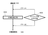
- FIG. 6 shows an example of the timing of the sizing agent application process in the process of manufacturing a reinforcing fiber bundle in the method of manufacturing a reinforcing fiber bundle according to the present invention.
- the sizing agent application process 400 is performed with the pattern A performed before the split treatment process 300.
- a pattern B to be performed after the fiber separation treatment process 300 is shown. Both timings of pattern A and pattern B are possible.
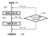
- FIG. 7 shows a timing example of the sizing agent application process 400 during the process of manufacturing the reinforcing fiber bundle in the method of manufacturing a reinforcing fiber bundle including the fiber bundle widening process 301 according to the present invention.
- the sizing agent applying step 400 is the fiber bundle widening step 301.
- a pattern C which is performed before the above, a pattern D which is performed between the fiber bundle widening step 301 and the separation processing step 300, and a pattern E which is performed after the separation processing step 300 are shown.
- the timing of the pattern D is most preferable from the viewpoint of achieving the optimum separation processing.
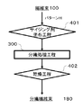
- FIG. 8 is the timing of the sizing agent application process including the sizing agent application process and the drying process in the manufacturing process of the reinforcing fiber bundle in the manufacturing method of the reinforcing fiber bundle which constitutes the fiber reinforced thermoplastic resin molding material according to the present invention.
- the sizing agent applying process 400 includes a sizing agent applying process 401 and a drying process 402.
- the sizing agent applying process 400 including the sizing agent applying process 401 and the drying process 402 is performed.
- a pattern F performed prior to the separation processing step 300 and a pattern G performed after the separation processing step 300 are shown in the process of forming the separation fiber bundle 180 through the processing step 300. There is. Either timing of pattern F or pattern G is possible.
- the pattern F is substantially the same as the pattern A in FIG. 6 and the pattern G is substantially the same as the pattern B in FIG.
- FIG. 9 is another manufacturing method of the reinforced fiber bundle which comprises the fiber reinforced thermoplastic resin molding material based on this invention WHEREIN:
- another sizing agent provision process including a sizing agent application process and a drying process
- the timing example of is shown.
- the sizing agent application process 401 and the drying process 402 in the sizing agent application process 400 are separated and performed at different timings.
- the sizing agent application step 401 is performed before the fiber separation treatment step 300, and the drying step 402 is performed after the fiber separation treatment step 300.
- FIG. 10 shows a timing example of a sizing agent application process including a sizing agent application process and a drying process in the method for producing a reinforced fiber bundle including the fiber bundle widening process according to the present invention, and the fiber bundle 100 is fiber bundle widening.
- the sizing agent applying step 401 of the sizing agent applying step is performed prior to the fiber bundle widening step 301,
- the drying step 402 a pattern I performed between the fiber bundle widening step 301 and the separation processing step 300 and a pattern J performed after the separation processing step 300 are shown.
- FIG. 11 shows another timing example of the sizing agent application process including the sizing agent application process and the drying process in the method for producing a reinforced fiber bundle including the fiber bundle widening process according to the present invention
- the fiber bundle 100 is a fiber
- the sizing agent application step 401 of the sizing agent application step comprises the fiber bundle widening step 301 and the splitting treatment step A pattern K is shown which is performed between 300 and 300, and the drying step 402 is performed after the separation processing step 300.
- the average bundle width of the chopped reinforcing fiber bundle constituting the fiber-reinforced thermoplastic resin molding material of the present invention is preferably 0.03 mm or more, more preferably 0.05 mm or more, and still more preferably 0.07 mm or more. If it is less than 0.03 mm, there is a concern that the flowability of the molding material may be poor. 3 mm or less is preferable, as for the average bundle
- the upper limit of the average number of fibers in the chopped reinforcing fiber bundle used in the present invention is preferably 4,000 or less, more preferably 3,000 or less, and still more preferably 2,000 or less. Within this range, the mechanical properties of the molded article can be enhanced.
- the lower limit of the number of fibers in the bundle is preferably 50 or more, more preferably 100 or more, and still more preferably 200 or more. Within this range, the flowability of the molding material can be enhanced. The method of deriving the average number of fibers will be described later.
- the width before immersing the chopped reinforcing fiber bundle after applying a sizing agent to water according to the present invention is W3 and the reinforcing fiber bundle is immersed in water at 25 ° C. for 5 minutes, then taken out and drained for 1 minute
- the width change ratio W4 / W3 of the reinforcing fiber bundle is preferably 0.6 or more, more preferably 0.7 or more, and still more preferably 0.8 or more.
- width change ratio W4 / W3 of the reinforcing fiber bundle is smaller than 0.6, the water-soluble physical properties of the sizing agent attached to the reinforcing fiber bundle remain, and the fiber bundle may reaggregate, Reaggregation makes it difficult to maintain the form of the fiber bundle adjusted to the optimum number of single yarns. If it can not be maintained in the form of a fiber bundle adjusted to the optimum number of single yarns, it can not be made an intermediate substrate of the optimum form, and it is possible to balance the flowability during molding and the mechanical properties of the molded article in a balanced manner. It will be difficult.
- the width change ratio W4 / W3 is preferably 1.1 or less.
- width change ratio W4 / W3 exceeds 1.1, the flexibility of the fiber bundle is lacking and the fiber bundle becomes too hard, and the bobbin may not be smoothly wound and unwound. In addition, single yarn breakage may occur at the time of cutting, which may result in failure to obtain an ideal chopped fiber bundle form.
- the method of deriving the width change ratio W4 / W3 of the reinforcing fiber bundle will be described later.
- the matrix thermoplastic resin to be impregnated into the bundle of chopped fiber bundles is not particularly limited.
- PBT polybutylene terephthalate
- PET polyethylene terephthalate
- PPS polypropylene
- PPS polyphenylene sulfide
- PEEK polyetheretherketone
- liquid crystal polymer polyvinyl chloride
- fluorine resin such as polytetrafluoroethylene, silicone, and the like.
- it is preferable to use a polyamide-based resin as the above-mentioned thermoplastic resin and it
- the thermoplastic polyamide resin used in the present invention can be obtained, for example, by polycondensation of nylon 6, nylon 11, nylon 12 or diamine and diamine with dicarboxylic acid obtained by ring-opening polymerization of cyclic lactam or polycondensation of ⁇ -aminocarboxylic acid.
- Copolymerized nylon such as 12 can be suitably used.
- nylon 6, 66, 610 is preferred in view of mechanical properties and cost.
- copper halide or derivatives thereof used in the present invention copper iodide, copper bromide, copper chloride, a complex salt of mercaptobenzimidazole and copper iodide, and the like can be mentioned. Among them, copper iodide and a complex salt of mercaptobenzimidazole and copper iodide can be suitably used.
- the addition amount of the copper halide or its derivative is preferably in the range of 0.001 to 5 parts by weight with respect to 100 parts by weight of the thermoplastic polyamide resin.
- the addition amount is less than 0.001 part, it is not possible to suppress resin decomposition, smoke and odor during preheating, and if it is 5 parts by weight or more, improvement of the improvement effect can not be observed. Furthermore, 0.002 to 1 part by weight is preferable because of the balance between the heat stabilization effect and the cost.
- the method for impregnating the bundle of chopped fiber bundles with the matrix resin is not particularly limited, and the method for impregnating the thermoplastic resin may be exemplified by a bundle of thermoplastic resin fibers.
- the thermoplastic resin fibers contained in the bundle-like aggregate may be used as it is as a matrix resin, or a bundle-like aggregate containing no thermoplastic resin fiber as a raw material, a fiber-reinforced thermoplastic resin molding material
- the matrix resin may be impregnated at any stage of production of.
- the matrix resin can be impregnated at any stage of producing a fiber-reinforced thermoplastic resin molding material.
- the resin constituting the thermoplastic resin fiber and the matrix resin may be the same resin or different resins.
- the resin constituting the thermoplastic resin fiber is different from the matrix resin, it is preferable that the two have compatibility or high affinity.
- impregnation of the bundle-like aggregate with the thermoplastic resin which is a matrix resin can be carried out using an impregnation press.
- the press is not particularly limited as long as it can realize the temperature and pressure necessary for the impregnation of the matrix resin, and a normal press having a flat platen which moves up and down, and a mechanism on which a pair of endless steel belts travel So-called double belt presses can be used.
- the matrix resin is formed into a sheet form such as a film, nonwoven fabric or woven fabric and then laminated with a discontinuous fiber mat, and the matrix resin can be melted and impregnated using the above-mentioned press or the like in that state.
- the particulate matrix resin may be dispersed on the bundle assembly to form a laminate, or the chopped fiber bundle may be dispersed at the same time as the dispersion and may be mixed inside the bundle assembly.
- the volume content of reinforcing fibers in the fiber-reinforced resin molding material is preferably 20% by volume or more of the total volume, more preferably 25% by volume or more, and still more preferably 30% by volume or more. If the volume content of reinforcing fibers is less than 20% by volume, the mechanical properties of the fiber-reinforced resin molding material also tend to decrease. On the other hand, the volume content of reinforcing fibers in the fiber-reinforced resin molding material is preferably 70% by volume or less, more preferably 65% by volume or less, and still more preferably 60% by volume or less. If the volume content of reinforcing fibers exceeds 70% by volume, the mechanical properties of the fiber-reinforced resin molding material are likely to be improved, but the moldability tends to be reduced.
- Reinforcing fiber bundle (1) Carbon fiber bundle ("PX35” manufactured by ZOLTEK, 50,000 single yarns, "13" (epoxy) sizing agent, sizing agent adhesion amount 1.5% by weight) was used.
- Reinforcing fiber bundle (2) A carbon fiber bundle ("PX35” manufactured by ZOLTEK, 50,000 single yarns, no sizing agent) was used.
- Reinforcing fiber bundle (3) A glass fiber bundle (240 TEX manufactured by Nitto Boshoku, 1,600 single yarns) was used.
- Resin Sheet (1) A sheet having a basis weight of 150 g / m 2 was produced using a polyamide masterbatch consisting of polyamide 6 resin ("Amilan” (registered trademark) CM 1001, manufactured by Toray Industries, Inc.).
- Resin sheet (2) 90% by mass of unmodified polypropylene resin (Prime Polymer Co., Ltd., “Prime PolyPro” (registered trademark) J106MG) and acid-modified polypropylene resin (Mitsui Chemical Co., Ltd., “Admar” Sheets were made using a polypropylene masterbatch consisting of 10% by weight (registered trademark) QE 800).
- Sizing agent (1) A water-soluble polyamide ("T-70" manufactured by Toray Industries, Inc.) was used.
- Sizing agent (2) A water-soluble polyamide ("A-90” manufactured by Toray Industries, Inc.) was used.
- Sizing agent (3) A water-soluble polyamide ("P-70” manufactured by Toray Industries, Inc.) was used.
- Sizing agent (4) A water-soluble polyamide ("P-95” manufactured by Toray Industries, Inc.) was used.
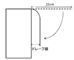
- the shortest distance between the tip of the reinforcing fiber bundle not fixed to the table and the side surface of the table was measured, and this was taken as the drape value D1.
- the measured reinforcing fiber bundle was immersed in water at 25 ° C. for 5 minutes, then taken out, and the water was removed.
- the reinforcing fiber bundle is dried at 80 ° C. under vacuum conditions for 24 hours, is absolutely dried, and is taken as a post-immersion treatment drape value D2 in the same manner as the above method.
- the hardness of the reinforcing fiber bundle was measured using HANDLE-O-Meter ("CAN-1 MCB" manufactured by Daiei Kagaku Seiki, Ltd.) according to JIS L-1096 E method (handle ohm method). .
- the reinforcing fiber bundle was opened and adjusted so that the length of the test piece used for hardness measurement was 10 cm, and the width was 1 mm with 1,700 to 550 filaments.
- the slit width was set to 20 mm.
- One reinforcing fiber bundle as a test piece was placed on the test table provided with the slit groove, and the resistance (g) generated when the test piece was pushed into the groove to a predetermined depth (8 mm) with a blade was measured. .
- the hardness of the reinforcing fiber bundle was obtained from the average value of three measurements.
- Wf weight content of reinforcing fibers in fiber-reinforced resin molding material
- the fiber-reinforced resin molding material was molded by a method described later to obtain a flat molded article of 500 ⁇ 400 mm.
- the flat plate longitudinal direction set to 0 °
- 16 pieces (total 32 pieces) of 100 ⁇ 25 ⁇ 2 mm test pieces are cut out from the obtained flat plate from 0 ° and 90 ° directions, respectively, according to JIS K 7074 (1988) .
- Bending strength was determined.
- the bending strength was determined to be A at 350 MPa or more and B at less than 350 MPa.
- resin sheet 2 in a state where two fiber reinforced resin molding materials of dimensions 150 mm ⁇ 150 mm ⁇ 2 mm are stacked, the temperature is raised to 120 ° C. after preheating so that the substrate center temperature (temperature between two sheets stacked) becomes 220 ° C. It was placed on a heated press platen and pressurized at 10 MPa for 30 seconds. The area A2 (mm 2 ) after this compression and the area A1 (mm 2 ) of the substrate before pressing were measured, and A2 / A1 ⁇ 100 was taken as the flow rate (%). The fluidity was determined to be less than 200% C, 200% or more and less than 300% B, and 300% or more A.
- the step of separating the reinforcing fiber bundle and the step passing property of continuously cutting and dispersing the divided reinforcing fiber bundle were determined as follows.
- C The reinforcing fiber bundle can not be separated. Alternatively, separation fibers can be used, but the separated reinforcing fiber bundle is wound eight times or more in ten times at the bobbin or cutter portion.
- Example 1 Unwind the reinforcing fiber bundle (1) at a constant speed of 10 m / min using a winder, pass it through a vibration widening roll oscillating in the axial direction at 10 Hz, apply a widening treatment, and then pass a 50 mm wide width regulating roll To obtain a reinforced fiber bundle expanded to 50 mm.
- the expanded reinforcing fiber bundle is continuously immersed in a resin treatment solution in which a secondary sizing agent (sizing agent (1)) is diluted with purified water, and then a 250 ° C. hot roller and a 250 ° C. drying oven (air) Under the atmosphere) and heat treatment for 1.5 minutes.
- a secondary sizing agent sizing agent (1)
- the sizing agent adhesion amount of the reinforcing fiber bundle was 0.1% by weight. In addition, this is the total adhesion amount which does not contain a primary sizing agent.
- An iron plate for separation processing equipped with a projecting shape with a thickness of 0.2 mm, a width of 3 mm, and a height of 20 mm with respect to the obtained reinforcing fiber bundle is parallel to the reinforcing fiber bundle width direction at 1 mm intervals.
- the set separation processing means was prepared. This separation processing means was intermittently pulled out and inserted into the reinforcing fiber bundle. At this time, the reinforcing fiber bundle traveling at a constant speed of 10 m / min was pierced with the separating treatment means for 3 seconds, the separating treatment means was removed in 0.2 seconds, and the process of piercing again was repeated. As shown in Table 1, the obtained fiber bundle width W3 was about 1 mm.
- the obtained reinforcing fiber bundle is continuously charged into a rotary cutter, cut at a fiber length of 25 mm, a cutting angle of 20 °, and dispersed so as to disperse uniformly, so that the fiber orientation is isotropic.
- a fiber non-woven fabric was obtained.
- the basis weight of the obtained discontinuous fiber non-woven fabric was 250 g / m 2 .
- Example 2 The evaluation was performed in the same manner as Example 1 except that the adhesion amount of the sizing agent (1) was 2% by weight. Table 1 shows the properties of the reinforced fiber bundle, process passability, mechanical properties, and flowability.
- Example 3 Unwind the reinforcing fiber bundle (1) at a constant speed of 10 m / min using a winder, pass it through a vibration widening roll that vibrates in the axial direction at 10 Hz, apply a widening process, and then pass a 30 mm wide width regulating roll To obtain a widened fiber bundle widened to 30 mm.
- Example 2 The evaluation was performed in the same manner as in Example 2 except that the widening width was set to 30 mm.
- Table 1 shows the properties of the reinforced fiber bundle, process passability, mechanical properties, and flowability.
- Example 4 Unwind the reinforcing fiber bundle (1) at a constant speed of 10 m / min using a winder, pass it through a vibration widening roll that vibrates in the axial direction at 10 Hz, apply a widening process, and then pass a 90 mm width regulating roll To obtain an expanded fiber bundle expanded to 85 mm.
- Example 2 The evaluation was performed in the same manner as in Example 2 except that the widening width was 85 mm.
- Table 1 shows the properties of the reinforced fiber bundle, process passability, mechanical properties, and flowability.
- Example 5 Evaluation was performed in the same manner as in Example 2 except that the heat treatment temperature and time of the secondary sizing agent were set to 350 ° C. and 16 minutes. Table 1 shows the properties of the reinforced fiber bundle, process passability, mechanical properties, and flowability.
- Example 6 Evaluation was performed in the same manner as in Example 2 except that the sizing agent (1) of the secondary sizing agent was changed to the sizing agent (2).
- Table 1 shows the properties of the reinforced fiber bundle, process passability, mechanical properties, and flowability.
- Example 7 Evaluation was performed in the same manner as in Example 2 except that the sizing agent (1) of the secondary sizing agent was changed to the sizing agent (3).
- Table 1 shows the properties of the reinforced fiber bundle, process passability, mechanical properties, and flowability.
- Example 8 Evaluation was performed in the same manner as in Example 2 except that the sizing agent (1) of the secondary sizing agent was changed to the sizing agent (4).
- Table 1 shows the properties of the reinforced fiber bundle, process passability, mechanical properties, and flowability.
- Example 1 The evaluation was performed in the same manner as in Example 1 except that the secondary sizing agent was not applied. Table 1 shows the properties of the reinforced fiber bundle, process passability, mechanical properties, and flowability.
- Example 9 The evaluation was performed in the same manner as in Example 2 except that the heat treatment temperature and time of the secondary sizing agent were set to 100 ° C. and 0.3 minutes. Table 1 shows the properties of the reinforced fiber bundle, process passability, mechanical properties, and flowability.
- Example 2 Evaluation was performed in the same manner as in Example 2 except that the reinforcing fiber bundle (1) was changed to the reinforcing fiber bundle (2).
- Table 1 shows the properties of the reinforced fiber bundle, process passability, mechanical properties, and flowability.
- the reinforcing fiber bundle (1) is unwound at a constant speed of 10 m / min using a winder, passed through a vibration widening roll oscillating in an axial direction at 10 Hz, subjected to a widening treatment, and then passed through a width regulating roll to 39 mm width A wide fiber bundle was obtained.
- a mother liquor in which the sizing agent (1) is dissolved in water is prepared and applied to a reinforcing fiber bundle (1) containing an epoxy sizing agent which is a crosslinking agent by a dipping method so as to obtain a coverage of 4.1% by weight. Drying was carried out with a hot roller at 250 ° C. for 0.5 minutes. As shown in Table 1, the fiber number per unit width of the reinforcing fiber bundle (1) was 1,290 fibers / mm, the bundle thickness was 0.07 mm, the drape value was 135 mm, and the bundle hardness was 78 g.
- separation processing means set in parallel at equal intervals of 1 mm were prepared. This separation processing means was intermittently pulled out and inserted from the widening fiber bundle to obtain a separation fiber bundle. At this time, the separation processing means pierces the separation processing means for 3 seconds against the widening fiber bundle traveling at a constant speed of 10 m / min to generate a separation processing section, and the separation processing means is removed in 0.2 seconds. The piercing operation was repeated to obtain a reinforced fiber bundle (1) having an average number of fibers in the bundle of 1,120 and an average bundle width of 0.6 mm.
- the fiber orientation isotropic by continuously inserting the obtained reinforcing fiber bundle (1) into a rotary cutter, cutting the fiber bundle to a fiber length of 15 mm, and dispersing it so as to be uniformly dispersed.
- a discontinuous fiber non-woven fabric was obtained.
- the basis weight of the obtained discontinuous fiber non-woven fabric was 0.25 kg / m 2 .
- the whole is sandwiched with a stainless steel plate, preheated at 270 ° C. for 90 seconds, and a pressure of 2.0 MPa is applied. While hot pressing at 240 ° C. for 180 seconds. Then, it was cooled to 50 ° C.
- the reinforcing fiber bundle (4) is unwound at a constant speed of 10 m / min using a winder, passed through a vibration widening roll oscillating in an axial direction at 10 Hz, subjected to a widening treatment, and then passed through a width regulating roll to a width of 32 mm. A wide fiber bundle was obtained.
- separation processing means set in parallel at equal intervals of 1 mm were prepared. This separation processing means was intermittently pulled out and inserted from the widening fiber bundle to obtain a separation fiber bundle. At this time, the separation processing means pierces the separation processing means for 3 seconds against the widening fiber bundle traveling at a constant speed of 10 m / min to generate a separation processing section, and the separation processing means is removed in 0.2 seconds. The piercing operation was repeated again to divide the expanded reinforcing fiber bundle (4) to obtain a reinforcing fiber bundle (4) having an average number of fibers in the bundle of 990 and an average bundle width of 0.6 mm.
- fiber orientation isotropic by continuously inserting the obtained reinforcing fiber bundle (4) into a rotary cutter, cutting the fiber bundle to a fiber length of 15 mm, and dispersing it so as to be uniformly dispersed.
- a discontinuous fiber non-woven fabric was obtained.
- the basis weight of the obtained discontinuous fiber non-woven fabric was 0.25 kg / m 2 .
- the whole is sandwiched with a stainless steel plate, preheated at 240 ° C. for 90 seconds, and a pressure of 2.0 MPa is applied. While hot pressing at 210 ° C. for 180 seconds. Then, it was cooled to 50 ° C.
- the reinforcing fiber bundle (4) is unwound at a constant speed of 10 m / min using a winder, passed through a vibration widening roll oscillating in an axial direction at 10 Hz, subjected to a widening treatment, and then passed through a width regulating roll to 34 mm width A wide fiber bundle was obtained.
- separation processing means set in parallel at equal intervals of 1 mm were prepared. This separation processing means was intermittently pulled out and inserted from the widening fiber bundle to obtain a separation fiber bundle. At this time, the separation processing means pierces the separation processing means for 3 seconds against the widening fiber bundle traveling at a constant speed of 10 m / min to generate a separation processing section, and the separation processing means is removed in 0.2 seconds. Repeat the piercing operation again to separate the widened reinforcing fiber bundle (4) and obtain a reinforcing fiber bundle (4) with an average number of fibers in the bundle of 1,030 and an average bundle width of 0.7 mm .
- fiber orientation isotropic by continuously inserting the obtained reinforcing fiber bundle (4) into a rotary cutter, cutting the fiber bundle to a fiber length of 15 mm, and dispersing it so as to be uniformly dispersed.
- a discontinuous fiber non-woven fabric was obtained.
- the basis weight of the obtained discontinuous fiber non-woven fabric was 0.25 kg / m 2 .
- the whole is sandwiched with a stainless steel plate, preheated at 270 ° C. for 90 seconds, and a pressure of 2.0 MPa is applied. While hot pressing at 240 ° C. for 180 seconds. Then, it was cooled to 50 ° C.
- the reinforcing fiber bundle (4) is unwound at a constant speed of 10 m / min using a winder, passed through a vibration widening roll oscillating in an axial direction at 10 Hz, subjected to a widening treatment, and then passed through a width regulating roll of 41 mm width A wide fiber bundle was obtained.
- the fiber number per unit width of the reinforcing fiber bundle (4) was 1,220 fibers / mm, the bundle thickness was 0.07 mm, the drape value was 233 mm, and the bundle hardness was 195 g.
- separation processing means set in parallel at equal intervals of 1 mm were prepared. This separation processing means was intermittently pulled out and inserted from the widening fiber bundle to obtain a separation fiber bundle. At this time, the separation processing means pierces the separation processing means for 3 seconds against the widening fiber bundle traveling at a constant speed of 10 m / min to generate a separation processing section, and the separation processing means is removed in 0.2 seconds. Repeat the piercing operation again to separate the widened reinforcing fiber bundle (4) and obtain a reinforcing fiber bundle (4) with an average number of fibers in the bundle of 1,880 and an average bundle width of 0.4 mm .
- fiber orientation isotropic by continuously inserting the obtained reinforcing fiber bundle (4) into a rotary cutter, cutting the fiber bundle to a fiber length of 15 mm, and dispersing it so as to be uniformly dispersed.
- a discontinuous fiber non-woven fabric was obtained.
- the basis weight of the obtained discontinuous fiber non-woven fabric was 0.25 kg / m 2 .
- the whole is sandwiched with a stainless steel plate, preheated at 270 ° C. for 90 seconds, and a pressure of 2.0 MPa is applied. While hot pressing at 240 ° C. for 180 seconds. Then, it was cooled to 50 ° C.
- the reinforcing fiber bundle (4) is unwound at a constant speed of 10 m / min using a winder, passed through a vibration widening roll oscillating in an axial direction at 10 Hz, subjected to a widening treatment, and then passed through a width regulating roll to 37 mm width A wide fiber bundle was obtained.
- the reinforcing fiber bundle (4) Adjusts the mother liquor dissolved in water so that the ratio of urea, which is a crosslinking agent, to the additional sizing agent (2) is 0.04, and so that the adhesion amount is 2.8% by weight, the reinforcing fiber bundle 4) and dried for 0.5 minutes with a hot roller at 250 ° C.
- the number of fibers per unit width of the reinforcing fiber bundle (4) was 1,350 fibers / mm
- the bundle thickness was 0.07 mm
- the drape value was 133 mm
- the bundle hardness was 78 g.
- separation processing means set in parallel at equal intervals of 1 mm were prepared. This separation processing means was intermittently pulled out and inserted from the widening fiber bundle to obtain a separation fiber bundle. At this time, the separation processing means pierces the separation processing means for 3 seconds against the widening fiber bundle traveling at a constant speed of 10 m / min to generate a separation processing section, and the separation processing means is removed in 0.2 seconds. Repeat the piercing operation again to separate the widened reinforcing fiber bundle (4) to obtain a reinforcing fiber bundle (4) having an average number of fibers in the bundle of 5,230 and an average bundle width of 3.4 mm. .
- fiber orientation isotropic by continuously inserting the obtained reinforcing fiber bundle (4) into a rotary cutter, cutting the fiber bundle to a fiber length of 15 mm, and dispersing it so as to be uniformly dispersed.
- a discontinuous fiber non-woven fabric was obtained.
- the basis weight of the obtained discontinuous fiber non-woven fabric was 0.25 kg / m 2 .
- the whole is sandwiched with a stainless steel plate, preheated at 270 ° C. for 90 seconds, and a pressure of 2.0 MPa is applied. While hot pressing at 240 ° C. for 180 seconds. Then, it was cooled to 50 ° C.
- Example 15 Unwind the reinforcing fiber bundle (3) at a constant speed of 10 m / min using a winder, pass it through a vibration widening roll that vibrates in the axial direction at 10 Hz, apply a widening treatment, and then pass a width regulating roll to 3 mm width A wide fiber bundle was obtained.
- separation processing means set in parallel at equal intervals of 1 mm were prepared. This separation processing means was intermittently pulled out and inserted from the widening fiber bundle to obtain a separation fiber bundle. At this time, the separation processing means pierces the separation processing means for 3 seconds against the widening fiber bundle traveling at a constant speed of 10 m / min to generate a separation processing section, and the separation processing means is removed in 0.2 seconds. The piercing operation was repeated to separate the widened reinforcing fiber bundle (3) to obtain a reinforcing fiber bundle (3) having an average number of fibers in the bundle of 410 and an average bundle width of 0.7 mm.
- fiber orientation isotropic by continuously inserting the obtained reinforcing fiber bundle (3) into a rotary cutter, cutting the fiber bundle to a fiber length of 15 mm, and dispersing it so as to be uniformly dispersed.
- a discontinuous fiber non-woven fabric was obtained.
- the basis weight of the obtained discontinuous fiber non-woven fabric was 0.25 kg / m 2 .
- the whole is sandwiched with a stainless steel plate, preheated at 240 ° C. for 90 seconds, and a pressure of 2.0 MPa is applied. While hot pressing at 210 ° C. for 180 seconds. Then, it was cooled to 50 ° C.
- the reinforcing fiber bundle (4) is unwound at a constant speed of 10 m / min using a winder, passed through a vibration widening roll oscillating in an axial direction at 10 Hz, subjected to a widening treatment, and then passed through a width regulating roll to 34 mm width A wide fiber bundle was obtained.
- separation processing means set in parallel at equal intervals of 1 mm were prepared. This separation processing means was intermittently pulled out and inserted from the widening fiber bundle to obtain a separation fiber bundle. At this time, the separation processing means pierces the separation processing means for 3 seconds against the widening fiber bundle traveling at a constant speed of 10 m / min to generate a separation processing section, and the separation processing means is removed in 0.2 seconds. The piercing operation was repeated to separate the widened reinforcing fiber bundle (4) to obtain a reinforcing fiber bundle (4) having an average number of fibers in the bundle of 930 and an average bundle width of 0.6 mm.
- fiber orientation isotropic by continuously inserting the obtained reinforcing fiber bundle (4) into a rotary cutter, cutting the fiber bundle to a fiber length of 15 mm, and dispersing it so as to be uniformly dispersed.
- a discontinuous fiber non-woven fabric was obtained.
- the basis weight of the obtained discontinuous fiber non-woven fabric was 0.25 kg / m 2 .
- the whole is sandwiched with a stainless steel plate, preheated at 270 ° C. for 90 seconds, and a pressure of 2.0 MPa is applied. While hot pressing at 240 ° C. for 180 seconds. Then, it was cooled to 50 ° C.
- Example 17 The reinforcing fiber bundle (4) is unwound using a winder at a constant speed of 10 m / min, passed through a vibration widening roll oscillating in an axial direction at 10 Hz, subjected to a widening treatment, and then passed through a width regulating roll to 28 mm width A wide fiber bundle was obtained.
- separation processing means set in parallel at equal intervals of 1 mm were prepared. This separation processing means was intermittently pulled out and inserted from the widening fiber bundle to obtain a separation fiber bundle. At this time, the separation processing means pierces the separation processing means for 3 seconds against the widening fiber bundle traveling at a constant speed of 10 m / min to generate a separation processing section, and the separation processing means is removed in 0.2 seconds. Repeat the piercing operation again to divide the widened reinforcing fiber bundle (4) to obtain a reinforcing fiber bundle (4) having an average number of fibers in the bundle of 1,540 and an average bundle width of 0.6 mm .
- fiber orientation isotropic by continuously inserting the obtained reinforcing fiber bundle (4) into a rotary cutter, cutting the fiber bundle to a fiber length of 15 mm, and dispersing it so as to be uniformly dispersed.
- a discontinuous fiber non-woven fabric was obtained.
- the basis weight of the obtained discontinuous fiber non-woven fabric was 0.25 kg / m 2 .
- the whole is sandwiched with a stainless steel plate, preheated at 270 ° C. for 90 seconds, and a pressure of 2.0 MPa is applied. While hot pressing at 240 ° C. for 180 seconds. Then, it was cooled to 50 ° C.
- Example 18 The reinforcing fiber bundle (4) is unwound at a constant speed of 10 m / min using a winder, passed through a vibration widening roll oscillating in an axial direction at 10 Hz, subjected to a widening treatment, and then passed through a width regulating roll to 13 mm width A wide fiber bundle was obtained.
- separation processing means set in parallel at equal intervals of 1 mm were prepared. This separation processing means was intermittently pulled out and inserted from the widening fiber bundle to obtain a separation fiber bundle. At this time, the separation processing means pierces the separation processing means for 3 seconds against the widening fiber bundle traveling at a constant speed of 10 m / min to generate a separation processing section, and the separation processing means is removed in 0.2 seconds. Repeat the piercing operation again to separate the widened reinforcing fiber bundle (4) and obtain a reinforcing fiber bundle (4) with an average number of fibers in the bundle of 1,120 and an average bundle width of 0.3 mm .
- fiber orientation isotropic by continuously inserting the obtained reinforcing fiber bundle (4) into a rotary cutter, cutting the fiber bundle to a fiber length of 15 mm, and dispersing it so as to be uniformly dispersed.
- a discontinuous fiber non-woven fabric was obtained.
- the basis weight of the obtained discontinuous fiber non-woven fabric was 0.25 kg / m 2 .
- the whole is sandwiched with a stainless steel plate, preheated at 240 ° C. for 90 seconds, and a pressure of 2.0 MPa is applied. While hot pressing at 210 ° C. for 180 seconds. Then, it was cooled to 50 ° C.
- the reinforcing fiber bundle (4) is unwound at a constant speed of 10 m / min using a winder, passed through a vibration widening roll oscillating in an axial direction at 10 Hz, subjected to a widening treatment, and then passed through a width regulating roll to a width of 11 mm. A wide fiber bundle was obtained.
- separation processing means set in parallel at equal intervals of 1 mm were prepared. This separation processing means was intermittently pulled out and inserted from the widening fiber bundle to obtain a separation fiber bundle. At this time, the separation processing means pierces the separation processing means for 3 seconds against the widening fiber bundle traveling at a constant speed of 10 m / min to generate a separation processing section, and the separation processing means is removed in 0.2 seconds. The piercing operation was repeated to separate the widened reinforcing fiber bundle (4) to obtain a reinforcing fiber bundle (4) having an average number of fibers in the bundle of 930 and an average bundle width of 0.6 mm.
- fiber orientation isotropic by continuously inserting the obtained reinforcing fiber bundle (4) into a rotary cutter, cutting the fiber bundle to a fiber length of 15 mm, and dispersing it so as to be uniformly dispersed.
- a discontinuous fiber non-woven fabric was obtained.
- the basis weight of the obtained discontinuous fiber non-woven fabric was 0.25 kg / m 2 .
- the whole is sandwiched with a stainless steel plate, preheated at 270 ° C. for 90 seconds, and a pressure of 2.0 MPa is applied. While hot pressing at 240 ° C. for 180 seconds. Then, it was cooled to 50 ° C.
- Example 20 The reinforcing fiber bundle (4) is unwound at a constant speed of 10 m / min using a winder, passed through a vibration widening roll oscillating in an axial direction at 10 Hz, subjected to a widening treatment, and then passed through a width regulating roll. A wide fiber bundle was obtained.
- separation processing means set in parallel at equal intervals of 1 mm were prepared. This separation processing means was intermittently pulled out and inserted from the widening fiber bundle to obtain a separation fiber bundle. At this time, the separation processing means pierces the separation processing means for 3 seconds against the widening fiber bundle traveling at a constant speed of 10 m / min to generate a separation processing section, and the separation processing means is removed in 0.2 seconds. Repeat the piercing operation again to separate the widened reinforcing fiber bundle (4) to obtain a reinforcing fiber bundle (4) having an average number of fibers in the bundle of 2,330 and an average bundle width of 0.7 mm. .
- fiber orientation isotropic by continuously inserting the obtained reinforcing fiber bundle (4) into a rotary cutter, cutting the fiber bundle to a fiber length of 15 mm, and dispersing it so as to be uniformly dispersed.
- a discontinuous fiber non-woven fabric was obtained.
- the basis weight of the obtained discontinuous fiber non-woven fabric was 0.25 kg / m 2 .
- the whole is sandwiched with a stainless steel plate, preheated at 270 ° C. for 90 seconds, and a pressure of 2.0 MPa is applied. While hot pressing at 240 ° C. for 180 seconds. Then, it was cooled to 50 ° C.
- Example 21 The reinforcing fiber bundle (4) is unwound using a winder at a constant speed of 10 m / min, passed through a vibration widening roll oscillating in an axial direction at 10 Hz, subjected to a widening treatment, and then passed through a width regulating roll to 33 mm width A wide fiber bundle was obtained.
- separation processing means set in parallel at equal intervals of 1 mm were prepared. This separation processing means was intermittently pulled out and inserted from the widening fiber bundle to obtain a separation fiber bundle. At this time, the separation processing means pierces the separation processing means for 3 seconds against the widening fiber bundle traveling at a constant speed of 10 m / min to generate a separation processing section, and the separation processing means is removed in 0.2 seconds. Repeat the piercing operation again to separate the widened reinforcing fiber bundle (4) and obtain a reinforcing fiber bundle (4) with an average number of fibers in the bundle of 2,110 and an average bundle width of 0.6 mm .
- fiber orientation isotropic by continuously inserting the obtained reinforcing fiber bundle (4) into a rotary cutter, cutting the fiber bundle to a fiber length of 15 mm, and dispersing it so as to be uniformly dispersed.
- a discontinuous fiber non-woven fabric was obtained.
- the basis weight of the obtained discontinuous fiber non-woven fabric was 0.25 kg / m 2 .
- the whole is sandwiched with a stainless steel plate, preheated at 270 ° C. for 90 seconds, and a pressure of 2.0 MPa is applied. While hot pressing at 240 ° C. for 180 seconds. Then, it was cooled to 50 ° C.
- the reinforcing fiber bundle (4) is unwound using a winder at a constant speed of 10 m / min, passed through a vibration widening roll oscillating in an axial direction at 10 Hz, subjected to a widening treatment, and then passed through a width regulating roll to 33 mm width A wide fiber bundle was obtained.
- separation processing means set in parallel at equal intervals of 1 mm were prepared. This separation processing means was intermittently pulled out and inserted from the widening fiber bundle to obtain a separation fiber bundle. At this time, the separation processing means pierces the separation processing means for 3 seconds against the widening fiber bundle traveling at a constant speed of 10 m / min to generate a separation processing section, and the separation processing means is removed in 0.2 seconds. Repeat the piercing operation again to divide the widened reinforcing fiber bundle (4) to obtain a reinforcing fiber bundle (4) with an average number of fibers in the bundle of 1,140 and an average bundle width of 0.7 mm. .
- fiber orientation isotropic by continuously inserting the obtained reinforcing fiber bundle (4) into a rotary cutter, cutting the fiber bundle to a fiber length of 15 mm, and dispersing it so as to be uniformly dispersed.
- a discontinuous fiber non-woven fabric was obtained.
- the basis weight of the obtained discontinuous fiber non-woven fabric was 0.25 kg / m 2 .
- the whole is sandwiched with a stainless steel plate, preheated at 270 ° C. for 90 seconds, and a pressure of 2.0 MPa is applied. While hot pressing at 240 ° C. for 180 seconds. Then, it was cooled to 50 ° C.
- the reinforcing fiber bundle (4) is unwound at a constant speed of 10 m / min using a winder, passed through a vibration widening roll oscillating in an axial direction at 10 Hz, subjected to a widening treatment, and then passed through a width regulating roll to 15 mm width A wide fiber bundle was obtained.
- separation processing means set in parallel at equal intervals of 1 mm were prepared. This separation processing means was intermittently pulled out and inserted from the widening fiber bundle to obtain a separation fiber bundle. At this time, the separation processing means pierces the separation processing means for 3 seconds against the widening fiber bundle traveling at a constant speed of 10 m / min to generate a separation processing section, and the separation processing means is removed in 0.2 seconds. Repeat the piercing operation again to divide the widened reinforcing fiber bundle (4) to obtain a reinforcing fiber bundle (4) having an average number of fibers in the bundle of 1,280 and an average bundle width of 0.7 mm. .
- fiber orientation isotropic by continuously inserting the obtained reinforcing fiber bundle (4) into a rotary cutter, cutting the fiber bundle to a fiber length of 15 mm, and dispersing it so as to be uniformly dispersed.
- a discontinuous fiber non-woven fabric was obtained.
- the basis weight of the obtained discontinuous fiber non-woven fabric was 0.25 kg / m 2 .
- the whole is sandwiched with a stainless steel plate, preheated at 270 ° C. for 90 seconds, and a pressure of 2.0 MPa is applied. While hot pressing at 240 ° C. for 180 seconds. Then, it was cooled to 50 ° C.
- Example 24 The reinforcing fiber bundle (4) is unwound at a constant speed of 10 m / min using a winder, passed through a vibration widening roll oscillating in an axial direction at 10 Hz, subjected to a widening treatment, and then passed through a width regulating roll to 34 mm width A wide fiber bundle was obtained.
- separation processing means set in parallel at equal intervals of 1 mm were prepared. This separation processing means was intermittently pulled out and inserted from the widening fiber bundle to obtain a separation fiber bundle. At this time, the separation processing means pierces the separation processing means for 3 seconds against the widening fiber bundle traveling at a constant speed of 10 m / min to generate a separation processing section, and the separation processing means is removed in 0.2 seconds. Repeat the piercing operation again to separate the widened reinforcing fiber bundle (4) and obtain a reinforcing fiber bundle (4) with an average number of fibers in the bundle of 1,180 and an average bundle width of 0.6 mm .
- fiber orientation isotropic by continuously inserting the obtained reinforcing fiber bundle (4) into a rotary cutter, cutting the fiber bundle to a fiber length of 15 mm, and dispersing it so as to be uniformly dispersed.
- a discontinuous fiber non-woven fabric was obtained.
- the basis weight of the obtained discontinuous fiber non-woven fabric was 0.25 kg / m 2 .
- the whole is sandwiched with a stainless steel plate, preheated at 270 ° C. for 90 seconds, and a pressure of 2.0 MPa is applied. While hot pressing at 240 ° C. for 180 seconds. Then, it was cooled to 50 ° C.
- the reinforcing fiber bundle (4) is unwound at a constant speed of 10 m / min using a winder, passed through a vibration widening roll oscillating in an axial direction at 10 Hz, subjected to a widening treatment, and then passed through a width regulating roll to 34 mm width A wide fiber bundle was obtained.
- separation processing means set in parallel at equal intervals of 1 mm were prepared. This separation processing means was intermittently pulled out and inserted from the widening fiber bundle to obtain a separation fiber bundle. At this time, the separation processing means pierces the separation processing means for 3 seconds against the widening fiber bundle traveling at a constant speed of 10 m / min to generate a separation processing section, and the separation processing means is removed in 0.2 seconds. Repeat the piercing operation again to separate the widened reinforcing fiber bundle (4) to obtain a reinforcing fiber bundle (4) with an average number of fibers in the bundle of 1,320 and an average bundle width of 0.02 mm. .
- fiber orientation isotropic by continuously inserting the obtained reinforcing fiber bundle (4) into a rotary cutter, cutting the fiber bundle to a fiber length of 15 mm, and dispersing it so as to be uniformly dispersed.
- a discontinuous fiber non-woven fabric was obtained.
- the basis weight of the obtained discontinuous fiber non-woven fabric was 0.25 kg / m 2 .
- the whole is sandwiched with a stainless steel plate, preheated at 270 ° C. for 90 seconds, and a pressure of 2.0 MPa is applied. While hot pressing at 240 ° C. for 180 seconds. Then, it was cooled to 50 ° C.
- the reinforcing fiber bundle (4) is unwound at a constant speed of 10 m / min using a winder, passed through a vibration widening roll oscillating in an axial direction at 10 Hz, subjected to a widening treatment, and then passed through a width regulating roll to 39 mm width A wide fiber bundle was obtained.
- a mother liquor in which the additional sizing agent (4) is dissolved in water is prepared, applied to the reinforcing fiber bundle (4) by the immersion method so as to obtain an adhesion amount of 2.7% by weight, 0. 2 by a hot roller at 250 ° C. Drying was performed for 5 minutes.
- the number of fibers per unit width of the reinforcing fiber bundle (4) was 1,270
- the bundle thickness was 0.07 mm
- the drape value was 112 mm
- the bundle hardness was 38 g.
- separation processing means set in parallel at equal intervals of 1 mm were prepared. This separation processing means was intermittently pulled out and inserted from the widening fiber bundle to obtain a separation fiber bundle. At this time, the separation processing means pierces the separation processing means for 3 seconds against the widening fiber bundle traveling at a constant speed of 10 m / min to generate a separation processing section, and the separation processing means is removed in 0.2 seconds. The piercing operation was repeated to separate the widened reinforcing fiber bundle (4) to obtain a reinforcing fiber bundle (4) having an average number of fibers in the bundle of 970 and an average bundle width of 0.6 mm.
- the fiber number per unit width of the reinforcing fiber bundle (1) was 1,230 fibers / mm
- the bundle thickness was 0.07 mm
- the drape value was 54 mm
- the bundle hardness was 27 g.
- a separation iron plate having a projecting shape with a thickness of 0.07 mm, a width of 3 mm and a height of 20 mm is provided in the width direction of the reinforcing fiber bundle
- separation processing means set in parallel at equal intervals of 1 mm were prepared. This separation processing means was intermittently pulled out and inserted from the widening fiber bundle to obtain a separation fiber bundle. At this time, the separation processing means pierces the separation processing means for 3 seconds against the widening fiber bundle traveling at a constant speed of 10 m / min to generate a separation processing section, and the separation processing means is removed in 0.2 seconds. The operation of piercing again was repeated, and the widened reinforcing fiber bundle (1) was separated to obtain a reinforcing fiber bundle (1) having an average number of fibers in the bundle of 930 and an average bundle width of 0.6 mm.
- the present invention can provide a reinforced fiber bundle and a chopped fiber bundle thereof which are excellent in productivity, flowability in molding, and mechanical characteristics of a molded article, a method of producing the same, and a fiber-reinforced resin molding material using the same.
- the reinforcing fiber bundle obtained by the manufacturing method of the present invention is a material of the discontinuous reinforcing fiber composite, and is mainly suitable for automobile interior and exterior, electric / electronic equipment housing, bicycle, aircraft interior material, transport box etc. Used.
Landscapes
- Chemical & Material Sciences (AREA)
- Chemical Kinetics & Catalysis (AREA)
- Engineering & Computer Science (AREA)
- Textile Engineering (AREA)
- Reinforced Plastic Materials (AREA)
- Treatments For Attaching Organic Compounds To Fibrous Goods (AREA)
Abstract
La présente invention concerne un faisceau de fibres de renforcement caractérisé en ce qu'un premier produit d'encollage comprenant n'importe quel composé ayant un groupe époxy, un groupe uréthane, un groupe amino, un groupe carboxyle, ou un autre groupe fonctionnel, ou un mélange de tels composés, et un second produit d'encollage comprenant une résine à base de polyamide sont collés sur les surfaces de fibres de renforcement. La présente invention concerne également un procédé de fabrication du faisceau de fibres de renforcement, et un faisceau de fibres coupées et un matériau de moulage de résine renforcé par des fibres où le faisceau de fibres de renforcement est utilisé. La présente invention concerne : un faisceau de fibres de renforcement ayant un excellent rendement de production ou une excellente fluidité de production pendant le moulage, et d'excellentes caractéristiques optiques dans un article moulé, et un faisceau de fibres coupées obtenu à partir du faisceau de fibres de renforcement ; un procédé de fabrication du faisceau de fibres de renforcement ; et un matériau de moulage de résine renforcé par des fibres dans lequel le faisceau de fibres de renforcement est utilisé.
Priority Applications (1)
| Application Number | Priority Date | Filing Date | Title |
|---|---|---|---|
| JP2019512692A JP7259740B2 (ja) | 2018-01-26 | 2019-01-17 | 強化繊維束およびその製造方法、ならびにそれを用いたチョップド繊維束および繊維強化樹脂成形材料 |
Applications Claiming Priority (4)
| Application Number | Priority Date | Filing Date | Title |
|---|---|---|---|
| JP2018-011451 | 2018-01-26 | ||
| JP2018011451 | 2018-01-26 | ||
| JP2018-011448 | 2018-01-26 | ||
| JP2018011448 | 2018-01-26 |
Publications (1)
| Publication Number | Publication Date |
|---|---|
| WO2019146486A1 true WO2019146486A1 (fr) | 2019-08-01 |
Family
ID=67394569
Family Applications (1)
| Application Number | Title | Priority Date | Filing Date |
|---|---|---|---|
| PCT/JP2019/001221 Ceased WO2019146486A1 (fr) | 2018-01-26 | 2019-01-17 | Faisceau de fibres de renforcement et son procédé de fabrication, et faisceau de fibres coupées et matériau de moulage de résine renforcé par des fibres utilisant celui-ci |
Country Status (2)
| Country | Link |
|---|---|
| JP (1) | JP7259740B2 (fr) |
| WO (1) | WO2019146486A1 (fr) |
Cited By (2)
| Publication number | Priority date | Publication date | Assignee | Title |
|---|---|---|---|---|
| CN115298006A (zh) * | 2020-03-18 | 2022-11-04 | 三菱化学株式会社 | Smc的制造方法 |
| CN115648664A (zh) * | 2022-10-25 | 2023-01-31 | 天津工业大学 | 一种碳纤维展宽定型复合处理方法 |
Citations (8)
| Publication number | Priority date | Publication date | Assignee | Title |
|---|---|---|---|---|
| JPH01292038A (ja) * | 1988-05-19 | 1989-11-24 | Toray Ind Inc | 開繊性の優れた無撚炭素繊維束、その製造法および製造装置 |
| JP2002138370A (ja) * | 2000-10-27 | 2002-05-14 | Toray Ind Inc | 炭素繊維チョップド糸及び繊維強化熱可塑性樹脂組成物 |
| JP2003105676A (ja) * | 2001-09-28 | 2003-04-09 | Toray Ind Inc | 炭素繊維、炭素繊維強化熱可塑性樹脂組成物、成形用材料および成形品 |
| JP2005526163A (ja) * | 2002-05-14 | 2005-09-02 | イー・アイ・デュポン・ドウ・ヌムール・アンド・カンパニー | 塗料用途のための架橋性ポリアミド組成物、かかる組成物を用いる方法およびかかる組成物から製造された物品 |
| WO2012081407A1 (fr) * | 2010-12-13 | 2012-06-21 | 東レ株式会社 | Préimprégné de fibres de carbone, son procédé de fabrication et matière composite renforcée par des fibres de carbone |
| JP2016194175A (ja) * | 2015-04-01 | 2016-11-17 | トヨタ自動車株式会社 | 樹脂コーティング炭素繊維およびその炭素繊維強化複合材 |
| WO2017221657A1 (fr) * | 2016-06-21 | 2017-12-28 | 東レ株式会社 | Faisceau de fibres partiellement séparées, procédé de production de faisceau de fibres partiellement séparées, matériau de moulage de résine renforcée par des fibres utilisant un faisceau de fibres partiellement séparées, et procédé de production d'un matériau de moulage de résine renforcée par des fibres utilisant un faisceau de fibres partiellement séparées |
| WO2018143067A1 (fr) * | 2017-02-02 | 2018-08-09 | 東レ株式会社 | Faisceau de fibres partiellement séparées et procédé de fabrication d'un tel faisceau de fibres partiellement séparées, faisceau de fibres coupées mettant en œuvre ledit faisceau de fibres partiellement séparées, et matériau de moulage en résine renforcé par des fibres |
-
2019
- 2019-01-17 WO PCT/JP2019/001221 patent/WO2019146486A1/fr not_active Ceased
- 2019-01-17 JP JP2019512692A patent/JP7259740B2/ja active Active
Patent Citations (8)
| Publication number | Priority date | Publication date | Assignee | Title |
|---|---|---|---|---|
| JPH01292038A (ja) * | 1988-05-19 | 1989-11-24 | Toray Ind Inc | 開繊性の優れた無撚炭素繊維束、その製造法および製造装置 |
| JP2002138370A (ja) * | 2000-10-27 | 2002-05-14 | Toray Ind Inc | 炭素繊維チョップド糸及び繊維強化熱可塑性樹脂組成物 |
| JP2003105676A (ja) * | 2001-09-28 | 2003-04-09 | Toray Ind Inc | 炭素繊維、炭素繊維強化熱可塑性樹脂組成物、成形用材料および成形品 |
| JP2005526163A (ja) * | 2002-05-14 | 2005-09-02 | イー・アイ・デュポン・ドウ・ヌムール・アンド・カンパニー | 塗料用途のための架橋性ポリアミド組成物、かかる組成物を用いる方法およびかかる組成物から製造された物品 |
| WO2012081407A1 (fr) * | 2010-12-13 | 2012-06-21 | 東レ株式会社 | Préimprégné de fibres de carbone, son procédé de fabrication et matière composite renforcée par des fibres de carbone |
| JP2016194175A (ja) * | 2015-04-01 | 2016-11-17 | トヨタ自動車株式会社 | 樹脂コーティング炭素繊維およびその炭素繊維強化複合材 |
| WO2017221657A1 (fr) * | 2016-06-21 | 2017-12-28 | 東レ株式会社 | Faisceau de fibres partiellement séparées, procédé de production de faisceau de fibres partiellement séparées, matériau de moulage de résine renforcée par des fibres utilisant un faisceau de fibres partiellement séparées, et procédé de production d'un matériau de moulage de résine renforcée par des fibres utilisant un faisceau de fibres partiellement séparées |
| WO2018143067A1 (fr) * | 2017-02-02 | 2018-08-09 | 東レ株式会社 | Faisceau de fibres partiellement séparées et procédé de fabrication d'un tel faisceau de fibres partiellement séparées, faisceau de fibres coupées mettant en œuvre ledit faisceau de fibres partiellement séparées, et matériau de moulage en résine renforcé par des fibres |
Cited By (2)
| Publication number | Priority date | Publication date | Assignee | Title |
|---|---|---|---|---|
| CN115298006A (zh) * | 2020-03-18 | 2022-11-04 | 三菱化学株式会社 | Smc的制造方法 |
| CN115648664A (zh) * | 2022-10-25 | 2023-01-31 | 天津工业大学 | 一种碳纤维展宽定型复合处理方法 |
Also Published As
| Publication number | Publication date |
|---|---|
| JPWO2019146486A1 (ja) | 2020-12-03 |
| JP7259740B2 (ja) | 2023-04-18 |
Similar Documents
| Publication | Publication Date | Title |
|---|---|---|
| JP6478180B2 (ja) | 部分分繊繊維束およびその製造方法、ならびにそれを用いたチョップド繊維束および繊維強化樹脂成形材料 | |
| US10569986B2 (en) | Partially separated fiber bundle, production method for partially separated fiber bundle, fiber-reinforced resin molding material using partially separated fiber bundle, and production method for fiber-reinforced resin molding material using partially separated fiber bundle | |
| CA3024095A1 (fr) | Faisceau de fibres partiellement separe, procede de production de faisceau de fibres partiellement separe, materiau de moulage en resine renforcee de fibres utilisant un faisceau de fibres partiellement separe, et procede de production d'un materiau de moulage en resine renforcee de fibres utilisant un faisceau de fibres partiellement separe | |
| US11162196B2 (en) | Partially separated fiber bundle, production method of partially separated fiber bundle, fiber-reinforced resin molding material using partially separated fiber bundle, and production method of fiber-reinforced resin molding material using partially separated fiber bundle | |
| US10907280B2 (en) | Production method for partially separated fiber bundle, partially separated fiber bundle, fiber-reinforced resin molding material using partially separated fiber bundle, and production method for fiber-reinforced resin molding material using partially separated fiber bundle | |
| WO2019146486A1 (fr) | Faisceau de fibres de renforcement et son procédé de fabrication, et faisceau de fibres coupées et matériau de moulage de résine renforcé par des fibres utilisant celui-ci | |
| JP7396046B2 (ja) | 部分分繊繊維束の製造方法 | |
| US11873376B2 (en) | Fiber-reinforced resin material and production method therefor | |
| CN111542655B (zh) | 增强纤维束 | |
| JP7363482B2 (ja) | 繊維強化樹脂成形材料及び成形品の製造方法 |
Legal Events
| Date | Code | Title | Description |
|---|---|---|---|
| ENP | Entry into the national phase |
Ref document number: 2019512692 Country of ref document: JP Kind code of ref document: A |
|
| 121 | Ep: the epo has been informed by wipo that ep was designated in this application |
Ref document number: 19743469 Country of ref document: EP Kind code of ref document: A1 |
|
| NENP | Non-entry into the national phase |
Ref country code: DE |
|
| 122 | Ep: pct application non-entry in european phase |
Ref document number: 19743469 Country of ref document: EP Kind code of ref document: A1 |