WO2019163301A1 - Dispositif de gestion, et système de stockage d'électricité - Google Patents
Dispositif de gestion, et système de stockage d'électricité Download PDFInfo
- Publication number
- WO2019163301A1 WO2019163301A1 PCT/JP2018/048558 JP2018048558W WO2019163301A1 WO 2019163301 A1 WO2019163301 A1 WO 2019163301A1 JP 2018048558 W JP2018048558 W JP 2018048558W WO 2019163301 A1 WO2019163301 A1 WO 2019163301A1
- Authority
- WO
- WIPO (PCT)
- Prior art keywords
- voltage
- cell
- cells
- ripple
- internal impedance
- Prior art date
- Legal status (The legal status is an assumption and is not a legal conclusion. Google has not performed a legal analysis and makes no representation as to the accuracy of the status listed.)
- Ceased
Links
Images


Classifications
-
- H—ELECTRICITY
- H02—GENERATION; CONVERSION OR DISTRIBUTION OF ELECTRIC POWER
- H02J—ELECTRIC POWER NETWORKS; CIRCUIT ARRANGEMENTS OR SYSTEMS FOR SUPPLYING OR DISTRIBUTING ELECTRIC POWER; SYSTEMS FOR STORING ELECTRIC ENERGY
- H02J7/00—Circuit arrangements for charging or discharging batteries or for supplying loads from batteries
- H02J7/60—Circuit arrangements for charging or discharging batteries or for supplying loads from batteries including safety or protection arrangements
- H02J7/62—Circuit arrangements for charging or discharging batteries or for supplying loads from batteries including safety or protection arrangements against overcurrent
-
- G—PHYSICS
- G01—MEASURING; TESTING
- G01R—MEASURING ELECTRIC VARIABLES; MEASURING MAGNETIC VARIABLES
- G01R31/00—Arrangements for testing electric properties; Arrangements for locating electric faults; Arrangements for electrical testing characterised by what is being tested not provided for elsewhere
- G01R31/36—Arrangements for testing, measuring or monitoring the electrical condition of accumulators or electric batteries, e.g. capacity or state of charge [SoC]
- G01R31/389—Measuring internal impedance, internal conductance or related variables
-
- G—PHYSICS
- G01—MEASURING; TESTING
- G01R—MEASURING ELECTRIC VARIABLES; MEASURING MAGNETIC VARIABLES
- G01R19/00—Arrangements for measuring currents or voltages or for indicating presence or sign thereof
- G01R19/165—Indicating that current or voltage is either above or below a predetermined value or within or outside a predetermined range of values
- G01R19/16533—Indicating that current or voltage is either above or below a predetermined value or within or outside a predetermined range of values characterised by the application
- G01R19/16538—Indicating that current or voltage is either above or below a predetermined value or within or outside a predetermined range of values characterised by the application in AC or DC supplies
- G01R19/16542—Indicating that current or voltage is either above or below a predetermined value or within or outside a predetermined range of values characterised by the application in AC or DC supplies for batteries
-
- G—PHYSICS
- G01—MEASURING; TESTING
- G01R—MEASURING ELECTRIC VARIABLES; MEASURING MAGNETIC VARIABLES
- G01R31/00—Arrangements for testing electric properties; Arrangements for locating electric faults; Arrangements for electrical testing characterised by what is being tested not provided for elsewhere
- G01R31/36—Arrangements for testing, measuring or monitoring the electrical condition of accumulators or electric batteries, e.g. capacity or state of charge [SoC]
- G01R31/382—Arrangements for monitoring battery or accumulator variables, e.g. SoC
- G01R31/3842—Arrangements for monitoring battery or accumulator variables, e.g. SoC combining voltage and current measurements
-
- G—PHYSICS
- G01—MEASURING; TESTING
- G01R—MEASURING ELECTRIC VARIABLES; MEASURING MAGNETIC VARIABLES
- G01R31/00—Arrangements for testing electric properties; Arrangements for locating electric faults; Arrangements for electrical testing characterised by what is being tested not provided for elsewhere
- G01R31/36—Arrangements for testing, measuring or monitoring the electrical condition of accumulators or electric batteries, e.g. capacity or state of charge [SoC]
- G01R31/396—Acquisition or processing of data for testing or for monitoring individual cells or groups of cells within a battery
-
- H—ELECTRICITY
- H01—ELECTRIC ELEMENTS
- H01M—PROCESSES OR MEANS, e.g. BATTERIES, FOR THE DIRECT CONVERSION OF CHEMICAL ENERGY INTO ELECTRICAL ENERGY
- H01M10/00—Secondary cells; Manufacture thereof
- H01M10/42—Methods or arrangements for servicing or maintenance of secondary cells or secondary half-cells
- H01M10/425—Structural combination with electronic components, e.g. electronic circuits integrated to the outside of the casing
- H01M10/4257—Smart batteries, e.g. electronic circuits inside the housing of the cells or batteries
-
- H—ELECTRICITY
- H01—ELECTRIC ELEMENTS
- H01M—PROCESSES OR MEANS, e.g. BATTERIES, FOR THE DIRECT CONVERSION OF CHEMICAL ENERGY INTO ELECTRICAL ENERGY
- H01M10/00—Secondary cells; Manufacture thereof
- H01M10/42—Methods or arrangements for servicing or maintenance of secondary cells or secondary half-cells
- H01M10/48—Accumulators combined with arrangements for measuring, testing or indicating the condition of cells, e.g. the level or density of the electrolyte
-
- H—ELECTRICITY
- H01—ELECTRIC ELEMENTS
- H01M—PROCESSES OR MEANS, e.g. BATTERIES, FOR THE DIRECT CONVERSION OF CHEMICAL ENERGY INTO ELECTRICAL ENERGY
- H01M10/00—Secondary cells; Manufacture thereof
- H01M10/42—Methods or arrangements for servicing or maintenance of secondary cells or secondary half-cells
- H01M10/48—Accumulators combined with arrangements for measuring, testing or indicating the condition of cells, e.g. the level or density of the electrolyte
- H01M10/482—Accumulators combined with arrangements for measuring, testing or indicating the condition of cells, e.g. the level or density of the electrolyte for several batteries or cells simultaneously or sequentially
-
- H—ELECTRICITY
- H01—ELECTRIC ELEMENTS
- H01M—PROCESSES OR MEANS, e.g. BATTERIES, FOR THE DIRECT CONVERSION OF CHEMICAL ENERGY INTO ELECTRICAL ENERGY
- H01M10/00—Secondary cells; Manufacture thereof
- H01M10/42—Methods or arrangements for servicing or maintenance of secondary cells or secondary half-cells
- H01M10/48—Accumulators combined with arrangements for measuring, testing or indicating the condition of cells, e.g. the level or density of the electrolyte
- H01M10/486—Accumulators combined with arrangements for measuring, testing or indicating the condition of cells, e.g. the level or density of the electrolyte for measuring temperature
-
- H—ELECTRICITY
- H02—GENERATION; CONVERSION OR DISTRIBUTION OF ELECTRIC POWER
- H02J—ELECTRIC POWER NETWORKS; CIRCUIT ARRANGEMENTS OR SYSTEMS FOR SUPPLYING OR DISTRIBUTING ELECTRIC POWER; SYSTEMS FOR STORING ELECTRIC ENERGY
- H02J7/00—Circuit arrangements for charging or discharging batteries or for supplying loads from batteries
- H02J7/02—Circuit arrangements for charging or discharging batteries or for supplying loads from batteries for charging batteries from AC mains by converters
-
- H—ELECTRICITY
- H02—GENERATION; CONVERSION OR DISTRIBUTION OF ELECTRIC POWER
- H02J—ELECTRIC POWER NETWORKS; CIRCUIT ARRANGEMENTS OR SYSTEMS FOR SUPPLYING OR DISTRIBUTING ELECTRIC POWER; SYSTEMS FOR STORING ELECTRIC ENERGY
- H02J7/00—Circuit arrangements for charging or discharging batteries or for supplying loads from batteries
- H02J7/80—Circuit arrangements for charging or discharging batteries or for supplying loads from batteries including monitoring or indicating arrangements
- H02J7/82—Control of state of charge [SOC]
-
- H—ELECTRICITY
- H02—GENERATION; CONVERSION OR DISTRIBUTION OF ELECTRIC POWER
- H02J—ELECTRIC POWER NETWORKS; CIRCUIT ARRANGEMENTS OR SYSTEMS FOR SUPPLYING OR DISTRIBUTING ELECTRIC POWER; SYSTEMS FOR STORING ELECTRIC ENERGY
- H02J7/00—Circuit arrangements for charging or discharging batteries or for supplying loads from batteries
- H02J7/80—Circuit arrangements for charging or discharging batteries or for supplying loads from batteries including monitoring or indicating arrangements
- H02J7/84—Control of state of health [SOH]
-
- B—PERFORMING OPERATIONS; TRANSPORTING
- B60—VEHICLES IN GENERAL
- B60L—PROPULSION OF ELECTRICALLY-PROPELLED VEHICLES; SUPPLYING ELECTRIC POWER FOR AUXILIARY EQUIPMENT OF ELECTRICALLY-PROPELLED VEHICLES; ELECTRODYNAMIC BRAKE SYSTEMS FOR VEHICLES IN GENERAL; MAGNETIC SUSPENSION OR LEVITATION FOR VEHICLES; MONITORING OPERATING VARIABLES OF ELECTRICALLY-PROPELLED VEHICLES; ELECTRIC SAFETY DEVICES FOR ELECTRICALLY-PROPELLED VEHICLES
- B60L3/00—Electric devices on electrically-propelled vehicles for safety purposes; Monitoring operating variables, e.g. speed, deceleration or energy consumption
-
- B—PERFORMING OPERATIONS; TRANSPORTING
- B60—VEHICLES IN GENERAL
- B60L—PROPULSION OF ELECTRICALLY-PROPELLED VEHICLES; SUPPLYING ELECTRIC POWER FOR AUXILIARY EQUIPMENT OF ELECTRICALLY-PROPELLED VEHICLES; ELECTRODYNAMIC BRAKE SYSTEMS FOR VEHICLES IN GENERAL; MAGNETIC SUSPENSION OR LEVITATION FOR VEHICLES; MONITORING OPERATING VARIABLES OF ELECTRICALLY-PROPELLED VEHICLES; ELECTRIC SAFETY DEVICES FOR ELECTRICALLY-PROPELLED VEHICLES
- B60L50/00—Electric propulsion with power supplied within the vehicle
- B60L50/40—Electric propulsion with power supplied within the vehicle using propulsion power supplied by capacitors
-
- B—PERFORMING OPERATIONS; TRANSPORTING
- B60—VEHICLES IN GENERAL
- B60L—PROPULSION OF ELECTRICALLY-PROPELLED VEHICLES; SUPPLYING ELECTRIC POWER FOR AUXILIARY EQUIPMENT OF ELECTRICALLY-PROPELLED VEHICLES; ELECTRODYNAMIC BRAKE SYSTEMS FOR VEHICLES IN GENERAL; MAGNETIC SUSPENSION OR LEVITATION FOR VEHICLES; MONITORING OPERATING VARIABLES OF ELECTRICALLY-PROPELLED VEHICLES; ELECTRIC SAFETY DEVICES FOR ELECTRICALLY-PROPELLED VEHICLES
- B60L50/00—Electric propulsion with power supplied within the vehicle
- B60L50/50—Electric propulsion with power supplied within the vehicle using propulsion power supplied by batteries or fuel cells
-
- B—PERFORMING OPERATIONS; TRANSPORTING
- B60—VEHICLES IN GENERAL
- B60L—PROPULSION OF ELECTRICALLY-PROPELLED VEHICLES; SUPPLYING ELECTRIC POWER FOR AUXILIARY EQUIPMENT OF ELECTRICALLY-PROPELLED VEHICLES; ELECTRODYNAMIC BRAKE SYSTEMS FOR VEHICLES IN GENERAL; MAGNETIC SUSPENSION OR LEVITATION FOR VEHICLES; MONITORING OPERATING VARIABLES OF ELECTRICALLY-PROPELLED VEHICLES; ELECTRIC SAFETY DEVICES FOR ELECTRICALLY-PROPELLED VEHICLES
- B60L53/00—Methods of charging batteries, specially adapted for electric vehicles; Charging stations or on-board charging equipment therefor; Exchange of energy storage elements in electric vehicles
-
- B—PERFORMING OPERATIONS; TRANSPORTING
- B60—VEHICLES IN GENERAL
- B60L—PROPULSION OF ELECTRICALLY-PROPELLED VEHICLES; SUPPLYING ELECTRIC POWER FOR AUXILIARY EQUIPMENT OF ELECTRICALLY-PROPELLED VEHICLES; ELECTRODYNAMIC BRAKE SYSTEMS FOR VEHICLES IN GENERAL; MAGNETIC SUSPENSION OR LEVITATION FOR VEHICLES; MONITORING OPERATING VARIABLES OF ELECTRICALLY-PROPELLED VEHICLES; ELECTRIC SAFETY DEVICES FOR ELECTRICALLY-PROPELLED VEHICLES
- B60L55/00—Arrangements for supplying energy stored within a vehicle to a power network, i.e. vehicle-to-grid [V2G] arrangements
-
- B—PERFORMING OPERATIONS; TRANSPORTING
- B60—VEHICLES IN GENERAL
- B60L—PROPULSION OF ELECTRICALLY-PROPELLED VEHICLES; SUPPLYING ELECTRIC POWER FOR AUXILIARY EQUIPMENT OF ELECTRICALLY-PROPELLED VEHICLES; ELECTRODYNAMIC BRAKE SYSTEMS FOR VEHICLES IN GENERAL; MAGNETIC SUSPENSION OR LEVITATION FOR VEHICLES; MONITORING OPERATING VARIABLES OF ELECTRICALLY-PROPELLED VEHICLES; ELECTRIC SAFETY DEVICES FOR ELECTRICALLY-PROPELLED VEHICLES
- B60L58/00—Methods or circuit arrangements for monitoring or controlling batteries or fuel cells, specially adapted for electric vehicles
-
- Y—GENERAL TAGGING OF NEW TECHNOLOGICAL DEVELOPMENTS; GENERAL TAGGING OF CROSS-SECTIONAL TECHNOLOGIES SPANNING OVER SEVERAL SECTIONS OF THE IPC; TECHNICAL SUBJECTS COVERED BY FORMER USPC CROSS-REFERENCE ART COLLECTIONS [XRACs] AND DIGESTS
- Y02—TECHNOLOGIES OR APPLICATIONS FOR MITIGATION OR ADAPTATION AGAINST CLIMATE CHANGE
- Y02E—REDUCTION OF GREENHOUSE GAS [GHG] EMISSIONS, RELATED TO ENERGY GENERATION, TRANSMISSION OR DISTRIBUTION
- Y02E60/00—Enabling technologies; Technologies with a potential or indirect contribution to GHG emissions mitigation
- Y02E60/10—Energy storage using batteries
-
- Y—GENERAL TAGGING OF NEW TECHNOLOGICAL DEVELOPMENTS; GENERAL TAGGING OF CROSS-SECTIONAL TECHNOLOGIES SPANNING OVER SEVERAL SECTIONS OF THE IPC; TECHNICAL SUBJECTS COVERED BY FORMER USPC CROSS-REFERENCE ART COLLECTIONS [XRACs] AND DIGESTS
- Y02—TECHNOLOGIES OR APPLICATIONS FOR MITIGATION OR ADAPTATION AGAINST CLIMATE CHANGE
- Y02T—CLIMATE CHANGE MITIGATION TECHNOLOGIES RELATED TO TRANSPORTATION
- Y02T10/00—Road transport of goods or passengers
- Y02T10/60—Other road transportation technologies with climate change mitigation effect
- Y02T10/70—Energy storage systems for electromobility, e.g. batteries
-
- Y—GENERAL TAGGING OF NEW TECHNOLOGICAL DEVELOPMENTS; GENERAL TAGGING OF CROSS-SECTIONAL TECHNOLOGIES SPANNING OVER SEVERAL SECTIONS OF THE IPC; TECHNICAL SUBJECTS COVERED BY FORMER USPC CROSS-REFERENCE ART COLLECTIONS [XRACs] AND DIGESTS
- Y02—TECHNOLOGIES OR APPLICATIONS FOR MITIGATION OR ADAPTATION AGAINST CLIMATE CHANGE
- Y02T—CLIMATE CHANGE MITIGATION TECHNOLOGIES RELATED TO TRANSPORTATION
- Y02T10/00—Road transport of goods or passengers
- Y02T10/60—Other road transportation technologies with climate change mitigation effect
- Y02T10/7072—Electromobility specific charging systems or methods for batteries, ultracapacitors, supercapacitors or double-layer capacitors
-
- Y—GENERAL TAGGING OF NEW TECHNOLOGICAL DEVELOPMENTS; GENERAL TAGGING OF CROSS-SECTIONAL TECHNOLOGIES SPANNING OVER SEVERAL SECTIONS OF THE IPC; TECHNICAL SUBJECTS COVERED BY FORMER USPC CROSS-REFERENCE ART COLLECTIONS [XRACs] AND DIGESTS
- Y02—TECHNOLOGIES OR APPLICATIONS FOR MITIGATION OR ADAPTATION AGAINST CLIMATE CHANGE
- Y02T—CLIMATE CHANGE MITIGATION TECHNOLOGIES RELATED TO TRANSPORTATION
- Y02T90/00—Enabling technologies or technologies with a potential or indirect contribution to GHG emissions mitigation
- Y02T90/10—Technologies relating to charging of electric vehicles
- Y02T90/14—Plug-in electric vehicles
Definitions
- the present invention relates to a management device and a power storage system that manage the states of a plurality of cells connected in series.
- Secondary batteries are used in various applications such as in-vehicle applications and stationary power storage applications (for example, backup, peak shift, FR (Frequency Regulation)).
- EV Electric (Vehicle)
- PHEV Plug-in Hybrid Electric Vehicle
- a voltage is measured for each cell, and it is monitored whether the cell voltage is within an allowable voltage range (see, for example, Patent Document 1).
- the cell voltage pulsates due to the influence of the ripple current, which may exceed the allowable voltage range of the cell.
- the cell voltage ripple is a minute voltage fluctuation
- a highly accurate voltage measurement circuit is required to monitor the cell voltage ripple with high accuracy. It is also necessary to sample the cell voltage at a sampling frequency that is twice or more the ripple frequency. To realize this, an expensive and large voltage measuring circuit (for example, an analog front end IC) is required. In particular, as the number of cells in series increases, the circuit scale increases and the system size and cost increase.
- the present invention has been made in view of such a situation, and an object of the present invention is to provide a technology capable of measuring ripples of respective voltages of a plurality of cells connected in series with an inexpensive and small circuit.
- a management device includes a cell voltage measurement unit that measures voltages of a plurality of cells connected in series, and a total voltage that measures a total voltage of the plurality of cells.
- a measurement unit ; and a control unit that manages internal impedances of the plurality of cells.
- the control unit detects the ripple of the total voltage measured by the total voltage measurement unit, and multiplies the detected ripple of the total voltage by the ratio of the internal impedance of each cell to the combined internal impedance of the plurality of cells.
- the ripple of the cell voltage is estimated, and it is determined whether or not the ripple of each cell voltage is within the allowable voltage range.
- the ripple of each voltage of a plurality of cells connected in series can be measured with an inexpensive and small circuit.
- FIGS. 3A to 3C are diagrams for explaining the influence of the ripple of the charging current flowing from the low-spec charger to the cell.
- FIGS. 4A and 4B are partial circuit diagrams illustrating a configuration example of the total voltage measurement unit. It is a flowchart for demonstrating the ripple measuring method of the electrical storage system which concerns on Embodiment 1 of this invention. It is a flowchart for demonstrating the ripple measuring method of the electrical storage system which concerns on Embodiment 2 of this invention.
- FIGS. 7A and 7B are partial circuit diagrams illustrating a configuration example according to the third embodiment.
- FIG. 1 is a diagram for explaining a power storage system 1 according to Embodiment 1 of the present invention.
- the example shown in FIG. 1 is an example in which the power storage system 1 according to the present embodiment is mounted on a vehicle as a driving battery for the vehicle.
- EV / PHEV that can be charged from a commercial power system (hereinafter simply referred to as system 5) is assumed.
- the power storage system 1 is connected to the motor 3 via the first relay SW1 and the inverter 2.
- the inverter 2 converts the DC power supplied from the power storage system 1 into AC power and supplies it to the motor 3 during power running.
- AC power supplied from the motor 3 is converted to DC power and supplied to the power storage system 1.
- the motor 3 is a three-phase AC motor, and rotates according to the AC power supplied from the inverter 2 during power running. At the time of regeneration, the rotational energy due to deceleration is converted into AC power and supplied to the inverter 2.
- 1st relay SW1 is inserted between the wiring which connects the electrical storage module 20 and the inverter 2 of the electrical storage system 1.
- FIG. When traveling, the management device 10 of the power storage system 1 controls the first relay SW1 to an on state (closed state), and electrically connects the power storage module 20 and the power system of the vehicle.
- the management device 10 controls the first relay SW1 to an off state (open state) as a general rule when the vehicle is not traveling, and electrically shuts off the power storage module 20 and the power system of the vehicle.
- switches such as semiconductor switches may be used instead of relays.
- the power storage system 1 includes a power storage module 20 and a management device 10.
- the power storage module 20 is formed by connecting a plurality of cells E1-Em in series.
- a lithium ion battery cell a nickel metal hydride battery cell, a lead battery cell, an electric double layer capacitor cell, a lithium ion capacitor cell, or the like can be used.
- a lithium ion battery cell nominal voltage: 3.6-3.7 V
- the number of cells E1-Em in series is determined according to the drive voltage of the motor 3.
- a shunt resistor Rs is connected in series with a plurality of cells E1-Em.
- the shunt resistor Rs functions as a current detection element.
- a Hall element may be used instead of the shunt resistor Rs.
- a temperature sensor T1 for detecting the temperature of the plurality of cells E1-Em is installed.
- a thermistor can be used as the temperature sensor T1.
- the management device 10 includes a total voltage measurement unit 11, a cell voltage measurement unit 12, a temperature measurement unit 13, a current measurement unit 14, a control unit 15, and a drive unit 16.
- the total voltage measuring unit 11 measures the voltage (total voltage) across the plurality of cells E1-Em connected in series. A configuration example of the total voltage measurement unit 11 will be described later.
- the cell voltage measurement unit 12 is connected to each node of a plurality of cells E1-Em connected in series by a plurality of voltage lines, and measures each voltage between two adjacent voltage lines, thereby allowing each cell E1- Measure Em voltage.
- the cell voltage measurement unit 12 transmits the measured voltage of each cell E1-Em to the control unit 15. Since the cell voltage measurement unit 12 has a higher voltage than the control unit 15, the cell voltage measurement unit 12 and the control unit 15 are connected by a communication line in an insulated state.
- the cell voltage measurement unit 12 can be configured by a general-purpose analog front-end IC or ASIC (Application Specific Integrated Circuit).
- the cell voltage measurement unit 12 includes a multiplexer and an A / D converter.
- the multiplexer outputs the voltage between two adjacent voltage lines to the A / D converter in order from the top.
- the A / D converter converts the analog voltage input from the multiplexer into a digital value.
- the large and expensive cell voltage measuring unit 12 is used, in addition to the multiplexer and the A / D converter, the number of differential amplifiers corresponding to the number of cells is included. Each differential amplifier amplifies the voltage between two adjacent voltage lines and outputs the amplified voltage to the multiplexer.
- the temperature measurement unit 13 includes a voltage dividing resistor and an A / D converter.
- the A / D converter converts the voltage divided by the temperature sensor T1 and the voltage dividing resistor into a digital value and outputs the digital value to the control unit 15.
- the controller 15 estimates the temperatures of the plurality of cells E1-Em based on the digital value.
- the current measuring unit 14 includes a differential amplifier and an A / D converter.
- the differential amplifier amplifies the voltage across the shunt resistor Rs and outputs it to the A / D converter.
- the A / D converter converts the voltage input from the differential amplifier into a digital value and outputs the digital value to the control unit 15.
- the control unit 15 estimates the current flowing through the plurality of cells E1-Em based on the digital value.
- the temperature measurement unit 13 and the current measurement unit 14 When an A / D converter is mounted in the control unit 15 and an analog input port is installed in the control unit 15, the temperature measurement unit 13 and the current measurement unit 14 output an analog voltage to the control unit 15.
- the digital value may be converted by an A / D converter in the control unit 15.
- the drive unit 16 generates a drive signal for opening and closing the first relay SW1 or the second relay SW2 based on the control signal from the control unit 15, and supplies the drive signal to the first relay SW1 or the second relay SW2.
- the control unit 15 is based on the total voltage, each voltage, current, and temperature of the plurality of cells E1-Em measured by the total voltage measurement unit 11, the cell voltage measurement unit 12, the temperature measurement unit 13, and the current measurement unit 14.
- the power storage module 20 is managed. For example, when an overvoltage, undervoltage, overcurrent, or temperature abnormality occurs in at least one of the plurality of cells E1-Em, the control unit 15 controls the drive unit 16 to turn on the first relay SW1 and / or the second relay SW2. Turn off and protect multiple cells E1-Em.
- the control unit 15 includes a calculation unit 15a and an internal impedance table 15b.
- the control unit 15 can be constituted by a microcomputer and a nonvolatile memory (for example, EEPROM, flash memory).
- the calculation unit 15a estimates the SOC (State Of Charge) and SOH (State Of Health) of each of the plurality of cells E1-Em.
- the SOC can be estimated by an OCV (Open Circuit Voltage) method or a current integration method.
- the OCV method is a method of estimating the SOC based on the OCV of each cell E1-Em measured by the cell voltage measuring unit 12 and the characteristic data of the SOC-OCV curve held in the nonvolatile memory.
- the current integrating method is a method of estimating the SOC based on the OCV at the start of charging / discharging of each cell E1-Em measured by the cell voltage measuring unit 12 and the integrated value of the current measured by the current measuring unit 14. is there.
- SOH is defined by the ratio of the current full charge capacity to the initial full charge capacity, and indicates that the lower the value (closer to 0%), the more the deterioration progresses.
- SOH may be obtained by capacity measurement by complete charge / discharge, or may be obtained by adding storage deterioration and cycle deterioration.
- Storage degradation can be estimated based on SOC, temperature, and storage degradation rate.
- Cycle degradation can be estimated based on the SOC range used, temperature, current rate, and cycle degradation rate.
- the storage deterioration rate and the cycle deterioration rate can be derived in advance by experiments or simulations.
- the SOC, temperature, SOC range, and current rate can be obtained by measurement.
- SOH can be estimated based on the correlation with the internal resistance of the cell.
- the internal resistance can be estimated by dividing a voltage drop generated when a predetermined current flows through the cell for a predetermined time by the current value.
- the internal resistance has a relationship that decreases as the temperature increases, and increases as the SOH decreases.
- Cell deterioration progresses as the number of charge / discharge cycles increases. Cell degradation also depends on individual differences and usage environment. Therefore, as the usage period becomes longer, the variation in the capacity of the plurality of cells E1-Em basically increases.
- the calculation unit 15a records the operation history including the voltage, current, temperature, SOC, and SOH of each cell E1-Em in the nonvolatile memory.
- An internal impedance table 15b is held in the nonvolatile memory.
- the internal impedance table 15b is a table describing a characteristic map of the internal impedance according to SOH, SOC, and temperature of the cell used in the power storage module 20.
- the characteristic map of the internal impedance can be derived based on experimental data measured while changing the conditions of SOH, SOC, and temperature, or simulation data calculated while changing these conditions.
- the present embodiment measures a ripple component corresponding to a frequency (100 Hz or 120 Hz in Japan) that is twice the commercial power frequency (50 Hz or 60 Hz in Japan) superimposed from the system 5.
- the characteristic map of the internal impedance is derived on the assumption that a voltage on which a ripple component having a frequency twice the commercial power supply frequency is superimposed is applied to the cell.
- a characteristic map of internal impedance for each frequency band may be derived in advance and described in the internal impedance table 15b.
- the power storage system 1 can be charged from the system 5 by being connected to the charger 4 installed outside the vehicle with the charging cable.
- the charger 4 is installed in a home, a card dealer, a service area, a commercial facility, a public facility, or the like.
- the charger 4 is connected to the system 5 and charges the power storage system 1 in the vehicle via a charging cable.
- the second relay SW2 is inserted between the wires connecting the power storage module 20 and the charger 4.
- the management device 10 controls the second relay SW2 to the on state (closed state) at the start of charging, and controls the second relay SW2 to the off state (open state) when the charging is completed.
- the management device 10 turns off the second relay SW2 when detecting an overvoltage, undervoltage, overcurrent, or temperature abnormality in at least one of the plurality of cells E1-Em, and turns off the plurality of cells.
- Protect E1-Em is inserted between the wires connecting the power storage module 20 and the charger 4.
- Charger 4 full-wave rectifies the AC power supplied from system 5 and smoothes it with a filter. Since it is difficult to remove all periodic components with a filter, a ripple component twice the commercial power supply frequency is superimposed on the output power of the charger 4.
- the high-spec charger removes ripple components from the output current including the high power factor converter called PFC (Power Factor Correction) circuit to suppress the harmonic current during charging, and the low frequency ripple of the PFC circuit, Since the DC / DC converter that controls the charging current is composed of two converters, the ripple of the output current of the charger is small.
- many low-spec chargers are configured to control the charging current with a PFC circuit. In that case, the ripple of the output current of the charger becomes large.
- FIG. 2 is a diagram illustrating an example of output waveforms of a charging current and a storage module voltage when charged with a low-spec charger.
- the example shown in FIG. 2 is an example of a state where the power storage module 20 is charged at a voltage of about 48 V, a charging current of about 23 A, and a charging power of about 1100 W.
- the pulsation of the charging current is increased. Since it is expected that such chargers will increase in the future, it is important to take measures against ripples on the power storage system 1 side.
- FIGS. 3A to 3C are diagrams for explaining the influence of the ripple of the charging current flowing from the low-spec charger to the cell.
- FIG. 3A is a diagram showing a simple equivalent circuit of the cell E1.
- the cell E1 is composed of a series circuit of an electromotive force E and an internal resistance Ri.
- FIG. 3B shows a waveform of the charging current i flowing through the cell E1 when charged from a low-spec charger.
- FIG.3 (c) is a figure which shows the voltage waveform of the cell E1 at the time of charging from a low specification charger.
- the voltage of the cell E1 also pulsates due to the influence.
- the ripple of the cell voltage is represented by a peak peak value that is a difference between the maximum voltage value and the minimum voltage value in a unit cycle. Note that the ripple of the cell voltage can be expressed by a maximum voltage value or a minimum voltage value with respect to a DC component in a unit cycle.
- the ripple of the cell voltage is a minute voltage fluctuation, a highly accurate voltage measurement circuit is required. It is also necessary to sample the cell voltage at a sampling frequency that is twice or more the ripple frequency. Therefore, it is conceivable to mount a high-spec cell voltage measurement unit 12.
- the high-spec cell voltage measurement unit 12 when the high-spec cell voltage measurement unit 12 is mounted, the cost increases and the circuit scale also increases. Especially in in-vehicle applications, the number of cells connected in series increases, so the system size and cost increase significantly. Therefore, in the present embodiment, a mechanism for estimating the ripple of each cell voltage from the ripple of the total voltage of the plurality of cells E1-Em is introduced.
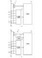
- FIGS. 4A to 4B are partial circuit diagrams showing a configuration example of the total voltage measuring unit 11.
- the total voltage measuring unit 11 includes a first voltage dividing resistor R1 and a second voltage dividing resistor R2 connected in series.
- the voltage divided by the first voltage dividing resistor R1 and the second voltage dividing resistor R2 is input to the analog input port of the control unit 15.
- An operational amplifier may be inserted between the voltage dividing circuit and the control unit 15.
- the control unit 15 samples the input voltage at a sampling frequency that is at least four times the commercial power supply frequency.
- the controller 15 detects the ripple of the total voltage by specifying the maximum voltage value and the minimum voltage value in the predetermined period.
- the predetermined period is set to a period corresponding to a frequency twice the commercial power supply frequency.
- the total voltage measuring unit 11 includes a first voltage dividing resistor R1 and a second voltage dividing resistor R2 connected in series, and a peak hold circuit 11a.
- a voltage divided by the first voltage dividing resistor R1 and the second voltage dividing resistor R2 is applied to the input terminal of the peak hold circuit 11a.
- the peak hold circuit 11a a general peak hold circuit using an operational amplifier, a diode, and a capacitor can be used.
- the peak hold circuit 11a can output the maximum voltage value or the minimum voltage value to the control unit 15 by resetting the capacitor every half cycle of the ripple cycle. In this configuration example, the control unit 15 can lower the sampling frequency.
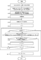
- FIG. 5 is a flowchart for explaining a ripple measuring method of power storage system 1 according to the first embodiment of the present invention.
- the control unit 15 of the management apparatus 10 specifies the SOC, temperature, and SOH of each cell E1-Em (S10).
- the control unit 15 specifies the internal impedance of each cell E1-Em with reference to the internal impedance table 15b based on the SOC, temperature, and SOH of each specified cell E1-Em (S11).
- the control unit 15 adds the internal impedances of the specified cells E1-Em, and calculates a combined internal impedance of the plurality of cells E1-Em connected in series (S12).
- the control unit 15 When charging of the power storage module 20 from the charger 4 is started (S13), the control unit 15 detects a ripple of the total voltage based on the voltage input from the total voltage measuring unit 11 (S14). The control unit 15 substitutes 1 as an initial value for the parameter n (S15).
- Control unit 15 monitors whether or not charging is completed (S16). When the charging is completed (Y in S16), the ripple measurement process is terminated. During charging (N in S16), the control unit 15 calculates the ripple of the nth cell voltage using the following (Equation 1) (S17).
- N ripple of nth cell voltage ripple of total voltage * (internal impedance / synthetic impedance of nth cell) (Equation 1)
- the control unit 15 determines whether or not the ripple of the nth cell voltage is within the allowable voltage range of the cell (S18). When the ripple of the nth cell voltage exceeds the allowable voltage range of the cell (N of S18) The control unit 15 opens the second relay SW2 (S111) and ends the ripple measurement process. When the ripple of the nth cell voltage is within the allowable voltage range of the cell (Y in S18), the control unit 15 increments the parameter n (S19). The control unit 15 compares the parameter n with the serial number m (S110). If the parameter n is equal to or smaller than the serial number m (N in S110), the process proceeds to step S16. When the parameter n exceeds the serial number m (Y in S110), the process proceeds to step S14.
- the ripple of each cell voltage is estimated by multiplying the ripple of the total voltage by the ratio of the internal impedance of each cell to the combined internal impedance of a plurality of cells.
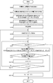
- FIG. 6 is a flowchart for explaining a ripple measuring method of power storage system 1 according to Embodiment 2 of the present invention.
- the control unit 15 of the management device 10 instructs the charger 4 to supply a constant current to the power storage module 20 for a predetermined period before starting charging from the charger 4 (S20).
- the control unit 15 can transmit the instruction to the charger 4 through communication using the communication line. Power line communication can also be used.
- the constant current value is preferably set to a small value.
- the control unit 15 detects the voltage change of each cell E1-Em before and after the supply of the constant current from the charger 4 (S21).
- the control unit 15 calculates the internal impedance of each cell E1-Em based on the constant current value supplied from the charger 4 and the voltage change value of each cell E1-Em (S22).
- the control unit 15 adds up the calculated internal impedances of the cells E1-Em to calculate a combined internal impedance of the plurality of cells E1-Em connected in series (S23).
- the processing from step S24 to step S212 is the same as the processing from step S13 to step S111 in the flowchart of FIG.
- the same effects as those of the first embodiment can be obtained. Furthermore, in the second embodiment, the internal impedance table 15b is unnecessary, so that development costs can be suppressed. Moreover, since the internal impedance of each cell E1-Em is measured based on the constant current from the charger 4 used for charging, high accuracy reflecting the ripple component superimposed from the charger 4 used for charging and the environmental conditions. Can be obtained.
- the ripple measurement method for the power storage system 1 according to Embodiment 3 of the present invention will be described.
- the total voltage of the plurality of cells E1-Em is measured, and the ripple of the cell voltage of one cell E1 is detected without detecting the ripple of the total voltage.
- the ratio of the internal impedance of one cell E1 and the internal impedance of each of the other cells E2-Em is multiplied by the ripple of the cell voltage of one cell E1, and the ripple of the cell voltage of each of the other cells E2-Em is obtained. presume.
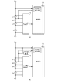
- FIGS. 7A to 7B are partial circuit diagrams showing a configuration example according to the third embodiment.
- the total voltage measuring unit 11 is omitted.
- the ripple detector 15c in the controller 15 detects a ripple of the cell voltage of one cell E1.
- the ripple of the total voltage of the plurality of cells E1-Em is detected by the ripple detector 15c in the controller 15.
- the structure which provides the ripple detection part 15c independently outside the control part 15 is also possible.
- the ripple of each cell voltage except one is changed to the ripple of the cell voltage of one cell, and the internal impedance of the one cell and the internal impedances of the other cells are It is estimated by multiplying by the ratio. As a result, only one measurement of the cell voltage ripple needs to be performed, and an increase in the system size and cost of the cell voltage measurement unit 12 can be suppressed.
- the above-described ripple measurement method can also be used in the stationary power storage system 1.
- the above ripple measurement method can also be used in the power storage system 1 for electronic devices such as notebook PCs and smartphones.
- a management device (10) characterized by estimating the ripple of each cell voltage by multiplying the ratio of the internal impedance of each cell (En) and determining whether the ripple of each cell voltage is within the allowable voltage range.
- the management device (10) according to any one of 1 to 4. According to this, the internal impedance of each cell (En) can be estimated with high accuracy.
- the controller (15) estimates an internal impedance of each cell (En) based on a voltage change of each cell (En) before and after a predetermined current is supplied to the plurality of cells (E1-Em).
- the management apparatus (10) according to any one of items 1 to 4, characterized in that: According to this, the internal impedance of each cell (En) can be estimated with high accuracy.
- the management device (10) according to any one of items 1 to 6, which manages the plurality of cells (E1-Em);
- a power storage system (1) comprising: According to this, it is possible to construct a power storage system (1) that can measure the ripple of each voltage of a plurality of cells (E1-Em) with an inexpensive and small-scale circuit.
Landscapes
- Engineering & Computer Science (AREA)
- Physics & Mathematics (AREA)
- General Physics & Mathematics (AREA)
- Power Engineering (AREA)
- Chemical Kinetics & Catalysis (AREA)
- Chemical & Material Sciences (AREA)
- Manufacturing & Machinery (AREA)
- Electrochemistry (AREA)
- General Chemical & Material Sciences (AREA)
- Microelectronics & Electronic Packaging (AREA)
- Secondary Cells (AREA)
- Charge And Discharge Circuits For Batteries Or The Like (AREA)
- Tests Of Electric Status Of Batteries (AREA)
Abstract
L'invention concerne une unité de mesure de tension de cellule (12) qui mesure les tensions aux bornes de chaque cellule d'une pluralité de cellules (E1 à Em) branchées en série. Une unité de mesure de tension totale (11) mesure la tension totale aux bornes de la pluralité de cellules (E1 à Em). Une unité de commande (15) gère l'impédance interne de chacune de la pluralité de cellules (E1 à Em). L'unité de commande (15) détecte une ondulation dans la tension totale mesurée par l'unité de mesure de tension totale (11), estime une ondulation dans chaque tension de cellule en multipliant l'ondulation détectée dans la tension totale par un rapport entre l'impédance interne de chaque cellule et une impédance interne composite de la pluralité de cellules (E1 à Em), et détermine si l'ondulation dans chaque tension de cellule se situe dans une plage de tension autorisée.
Priority Applications (3)
| Application Number | Priority Date | Filing Date | Title |
|---|---|---|---|
| CN201880088681.8A CN111684291B (zh) | 2018-02-23 | 2018-12-28 | 管理装置、蓄电系统 |
| US16/765,920 US11258113B2 (en) | 2018-02-23 | 2018-12-28 | Management device, and electricity storage system |
| JP2020502062A JP7149543B2 (ja) | 2018-02-23 | 2018-12-28 | 管理装置、蓄電システム |
Applications Claiming Priority (2)
| Application Number | Priority Date | Filing Date | Title |
|---|---|---|---|
| JP2018-031228 | 2018-02-23 | ||
| JP2018031228 | 2018-02-23 |
Publications (1)
| Publication Number | Publication Date |
|---|---|
| WO2019163301A1 true WO2019163301A1 (fr) | 2019-08-29 |
Family
ID=67686751
Family Applications (1)
| Application Number | Title | Priority Date | Filing Date |
|---|---|---|---|
| PCT/JP2018/048558 Ceased WO2019163301A1 (fr) | 2018-02-23 | 2018-12-28 | Dispositif de gestion, et système de stockage d'électricité |
Country Status (4)
| Country | Link |
|---|---|
| US (1) | US11258113B2 (fr) |
| JP (1) | JP7149543B2 (fr) |
| CN (1) | CN111684291B (fr) |
| WO (1) | WO2019163301A1 (fr) |
Cited By (4)
| Publication number | Priority date | Publication date | Assignee | Title |
|---|---|---|---|---|
| JP7311184B1 (ja) | 2022-03-07 | 2023-07-19 | Necプラットフォームズ株式会社 | 電池管理装置、電池管理方法、及びプログラム |
| JP2023116290A (ja) * | 2022-02-09 | 2023-08-22 | 河村電器産業株式会社 | 蓄電池の劣化診断システム |
| WO2023189370A1 (fr) * | 2022-03-28 | 2023-10-05 | ヌヴォトンテクノロジージャパン株式会社 | Dispositif de mesure |
| US12416678B2 (en) | 2022-07-22 | 2025-09-16 | Analog Devices International Unlimited Company | Distributed battery monitoring system |
Families Citing this family (6)
| Publication number | Priority date | Publication date | Assignee | Title |
|---|---|---|---|---|
| JP6791180B2 (ja) * | 2018-03-01 | 2020-11-25 | Tdk株式会社 | センサ |
| DE102019002309A1 (de) * | 2019-03-29 | 2019-11-14 | Daimler Ag | Verfahren zum Bestimmen einer elektrlschen Zellspannung elner Batteriezelle einer Traktionsbatterie eines Fahrzeugs sowie Vorrichtung |
| US11509145B2 (en) * | 2019-06-14 | 2022-11-22 | X-wave Innovations, Inc. | In-situ on-line and embedded battery impedance measurement device using active balancing circuits |
| US20230208169A1 (en) * | 2021-12-29 | 2023-06-29 | Auto Motive Power Inc. | Technique Using a Battery Charger and Battery Management System to Detect Cell Degradation and Pack Imminent Failures |
| US20230294524A1 (en) * | 2022-03-17 | 2023-09-21 | Transportation Ip Holdings, Llc | Energy management system |
| JP2026057927A (ja) | 2024-09-24 | 2026-04-03 | トヨタ自動車株式会社 | 二次電池の充電システム及び充電方法 |
Citations (6)
| Publication number | Priority date | Publication date | Assignee | Title |
|---|---|---|---|---|
| JPH0833222A (ja) * | 1994-07-08 | 1996-02-02 | Toshiba Corp | 二次電池の充電回路及びこれを用いた二次電池式クリーナ |
| JP2012235592A (ja) * | 2011-04-28 | 2012-11-29 | Toyota Motor Corp | 車両の充電制御装置および充電制御方法 |
| JP2013238405A (ja) * | 2012-05-11 | 2013-11-28 | Calsonic Kansei Corp | 組電池のセルの状態推定装置 |
| JP2014086351A (ja) * | 2012-10-25 | 2014-05-12 | Gs Yuasa Corp | 蓄電モジュールの監視装置 |
| JP2014110728A (ja) * | 2012-12-04 | 2014-06-12 | Toyota Motor Corp | 電池システムおよびそれを備える車両 |
| WO2015189983A1 (fr) * | 2014-06-13 | 2015-12-17 | 日産自動車株式会社 | Dispositif de commande de charge et procédé de commande de charge |
Family Cites Families (12)
| Publication number | Priority date | Publication date | Assignee | Title |
|---|---|---|---|---|
| JP3508551B2 (ja) | 1998-06-23 | 2004-03-22 | 株式会社日立製作所 | 蓄電器制御装置 |
| DE60335878D1 (de) * | 2002-04-23 | 2011-03-10 | Nanopower Solutions Inc | Rauschfilterschaltung |
| CN1240177C (zh) * | 2003-06-09 | 2006-02-01 | 清华大学 | 有直流源的支路阻抗解耦控制的有源电力滤波方法及系统 |
| CN1305195C (zh) * | 2003-06-09 | 2007-03-14 | 清华大学 | 逆变电容和支路电抗解耦控制的有源电力滤波方法及系统 |
| US7880577B1 (en) * | 2006-08-25 | 2011-02-01 | Lockheed Martin Corporation | Current doubler rectifier with current ripple cancellation |
| WO2009028837A1 (fr) * | 2007-08-29 | 2009-03-05 | Powertron Engineering Co., Ltd | Appareil de diagnostic de l'état de vieillissement d'un système de conversion de puissance et procédé associé |
| JP2014134488A (ja) * | 2013-01-11 | 2014-07-24 | Mitsubishi Electric Corp | 電池監視装置 |
| EP2988144B1 (fr) * | 2013-04-19 | 2018-03-07 | Hitachi Automotive Systems, Ltd. | Dispositif de surveillance de système de batterie |
| KR20150081731A (ko) * | 2014-01-06 | 2015-07-15 | 삼성에스디아이 주식회사 | 배터리 팩, 배터리 팩을 포함하는 에너지 저장 시스템, 배터리 팩의 작동 방법 |
| WO2016143012A1 (fr) * | 2015-03-06 | 2016-09-15 | 日産自動車株式会社 | Système d'ajustement de puissance et son procédé de commande |
| US10161978B2 (en) * | 2016-03-01 | 2018-12-25 | Texas Instruments Incorporated | Impedance analyzer using square wave stimuli |
| CN206712453U (zh) * | 2016-12-23 | 2017-12-05 | 深圳市深波电子有限公司 | 一种带火灾防护功能的浪涌智能防护装置 |
-
2018
- 2018-12-28 JP JP2020502062A patent/JP7149543B2/ja active Active
- 2018-12-28 US US16/765,920 patent/US11258113B2/en active Active
- 2018-12-28 CN CN201880088681.8A patent/CN111684291B/zh active Active
- 2018-12-28 WO PCT/JP2018/048558 patent/WO2019163301A1/fr not_active Ceased
Patent Citations (6)
| Publication number | Priority date | Publication date | Assignee | Title |
|---|---|---|---|---|
| JPH0833222A (ja) * | 1994-07-08 | 1996-02-02 | Toshiba Corp | 二次電池の充電回路及びこれを用いた二次電池式クリーナ |
| JP2012235592A (ja) * | 2011-04-28 | 2012-11-29 | Toyota Motor Corp | 車両の充電制御装置および充電制御方法 |
| JP2013238405A (ja) * | 2012-05-11 | 2013-11-28 | Calsonic Kansei Corp | 組電池のセルの状態推定装置 |
| JP2014086351A (ja) * | 2012-10-25 | 2014-05-12 | Gs Yuasa Corp | 蓄電モジュールの監視装置 |
| JP2014110728A (ja) * | 2012-12-04 | 2014-06-12 | Toyota Motor Corp | 電池システムおよびそれを備える車両 |
| WO2015189983A1 (fr) * | 2014-06-13 | 2015-12-17 | 日産自動車株式会社 | Dispositif de commande de charge et procédé de commande de charge |
Cited By (5)
| Publication number | Priority date | Publication date | Assignee | Title |
|---|---|---|---|---|
| JP2023116290A (ja) * | 2022-02-09 | 2023-08-22 | 河村電器産業株式会社 | 蓄電池の劣化診断システム |
| JP7311184B1 (ja) | 2022-03-07 | 2023-07-19 | Necプラットフォームズ株式会社 | 電池管理装置、電池管理方法、及びプログラム |
| JP2023129981A (ja) * | 2022-03-07 | 2023-09-20 | Necプラットフォームズ株式会社 | 電池管理装置、電池管理方法、及びプログラム |
| WO2023189370A1 (fr) * | 2022-03-28 | 2023-10-05 | ヌヴォトンテクノロジージャパン株式会社 | Dispositif de mesure |
| US12416678B2 (en) | 2022-07-22 | 2025-09-16 | Analog Devices International Unlimited Company | Distributed battery monitoring system |
Also Published As
| Publication number | Publication date |
|---|---|
| US11258113B2 (en) | 2022-02-22 |
| JP7149543B2 (ja) | 2022-10-07 |
| CN111684291A (zh) | 2020-09-18 |
| JPWO2019163301A1 (ja) | 2021-03-11 |
| CN111684291B (zh) | 2023-07-07 |
| US20200365951A1 (en) | 2020-11-19 |
Similar Documents
| Publication | Publication Date | Title |
|---|---|---|
| JP7149543B2 (ja) | 管理装置、蓄電システム | |
| KR102949540B1 (ko) | 배터리 관리 시스템, 배터리 팩, 전기 차량 및 배터리 관리 방법 | |
| JP7163313B2 (ja) | 管理装置、及び電源システム | |
| JP7182110B2 (ja) | 電池システム、電池管理装置 | |
| JP5687340B2 (ja) | 電池制御装置、電池システム | |
| US9231407B2 (en) | Battery system, method of controlling the same, and energy storage system including the battery system | |
| US11277011B2 (en) | Management device, power storage system | |
| US11158888B2 (en) | Management device and power storage system | |
| JP7573195B2 (ja) | 管理装置、及び電源システム | |
| US20150070024A1 (en) | Battery pack, apparatus including battery pack, and method of managing battery pack | |
| US20180292462A1 (en) | State of charge calculation apparatus for secondary battery and storage battery system | |
| CN114814627A (zh) | 电池诊断装置 | |
| JP7046750B2 (ja) | 電源システム、及び管理装置 | |
| WO2019171662A1 (fr) | Dispositif de gestion et système de stockage d'électricité | |
| JP2008011657A (ja) | 電源装置 | |
| CN110391473A (zh) | 用于对电能量存储单元充电的方法 | |
| KR102960850B1 (ko) | 배터리 관리 시스템, 배터리 팩, 전기 차량 및 배터리 관리 방법 | |
| JP7627252B2 (ja) | 蓄電池制御装置、及び蓄電システム | |
| JP7562598B2 (ja) | 蓄電池制御装置、蓄電システム、及び蓄電池制御方法 | |
| CN104104130B (zh) | 电压补偿的主动电池平衡 |
Legal Events
| Date | Code | Title | Description |
|---|---|---|---|
| 121 | Ep: the epo has been informed by wipo that ep was designated in this application |
Ref document number: 18907184 Country of ref document: EP Kind code of ref document: A1 |
|
| ENP | Entry into the national phase |
Ref document number: 2020502062 Country of ref document: JP Kind code of ref document: A |
|
| NENP | Non-entry into the national phase |
Ref country code: DE |
|
| 122 | Ep: pct application non-entry in european phase |
Ref document number: 18907184 Country of ref document: EP Kind code of ref document: A1 |