WO2019163539A1 - Connecteur - Google Patents
Connecteur Download PDFInfo
- Publication number
- WO2019163539A1 WO2019163539A1 PCT/JP2019/004484 JP2019004484W WO2019163539A1 WO 2019163539 A1 WO2019163539 A1 WO 2019163539A1 JP 2019004484 W JP2019004484 W JP 2019004484W WO 2019163539 A1 WO2019163539 A1 WO 2019163539A1
- Authority
- WO
- WIPO (PCT)
- Prior art keywords
- rotation axis
- main surface
- distance
- actuator
- cable
- Prior art date
- Legal status (The legal status is an assumption and is not a legal conclusion. Google has not performed a legal analysis and makes no representation as to the accuracy of the status listed.)
- Ceased
Links
Images




Classifications
-
- H—ELECTRICITY
- H01—ELECTRIC ELEMENTS
- H01R—ELECTRICALLY-CONDUCTIVE CONNECTIONS; STRUCTURAL ASSOCIATIONS OF A PLURALITY OF MUTUALLY-INSULATED ELECTRICAL CONNECTING ELEMENTS; COUPLING DEVICES; CURRENT COLLECTORS
- H01R12/00—Structural associations of a plurality of mutually-insulated electrical connecting elements, specially adapted for printed circuits, e.g. printed circuit boards [PCB], flat or ribbon cables, or like generally planar structures, e.g. terminal strips, terminal blocks; Coupling devices specially adapted for printed circuits, flat or ribbon cables, or like generally planar structures; Terminals specially adapted for contact with, or insertion into, printed circuits, flat or ribbon cables, or like generally planar structures
- H01R12/70—Coupling devices
- H01R12/82—Coupling devices connected with low or zero insertion force
- H01R12/85—Coupling devices connected with low or zero insertion force contact pressure producing means, contacts activated after insertion of printed circuits or like structures
- H01R12/88—Coupling devices connected with low or zero insertion force contact pressure producing means, contacts activated after insertion of printed circuits or like structures acting manually by rotating or pivoting connector housing parts
-
- H—ELECTRICITY
- H01—ELECTRIC ELEMENTS
- H01R—ELECTRICALLY-CONDUCTIVE CONNECTIONS; STRUCTURAL ASSOCIATIONS OF A PLURALITY OF MUTUALLY-INSULATED ELECTRICAL CONNECTING ELEMENTS; COUPLING DEVICES; CURRENT COLLECTORS
- H01R12/00—Structural associations of a plurality of mutually-insulated electrical connecting elements, specially adapted for printed circuits, e.g. printed circuit boards [PCB], flat or ribbon cables, or like generally planar structures, e.g. terminal strips, terminal blocks; Coupling devices specially adapted for printed circuits, flat or ribbon cables, or like generally planar structures; Terminals specially adapted for contact with, or insertion into, printed circuits, flat or ribbon cables, or like generally planar structures
- H01R12/70—Coupling devices
- H01R12/71—Coupling devices for rigid printing circuits or like structures
-
- H—ELECTRICITY
- H01—ELECTRIC ELEMENTS
- H01R—ELECTRICALLY-CONDUCTIVE CONNECTIONS; STRUCTURAL ASSOCIATIONS OF A PLURALITY OF MUTUALLY-INSULATED ELECTRICAL CONNECTING ELEMENTS; COUPLING DEVICES; CURRENT COLLECTORS
- H01R12/00—Structural associations of a plurality of mutually-insulated electrical connecting elements, specially adapted for printed circuits, e.g. printed circuit boards [PCB], flat or ribbon cables, or like generally planar structures, e.g. terminal strips, terminal blocks; Coupling devices specially adapted for printed circuits, flat or ribbon cables, or like generally planar structures; Terminals specially adapted for contact with, or insertion into, printed circuits, flat or ribbon cables, or like generally planar structures
- H01R12/70—Coupling devices
- H01R12/77—Coupling devices for flexible printed circuits, flat or ribbon cables or like structures
- H01R12/79—Coupling devices for flexible printed circuits, flat or ribbon cables or like structures connecting to rigid printed circuits or like structures
-
- H—ELECTRICITY
- H01—ELECTRIC ELEMENTS
- H01R—ELECTRICALLY-CONDUCTIVE CONNECTIONS; STRUCTURAL ASSOCIATIONS OF A PLURALITY OF MUTUALLY-INSULATED ELECTRICAL CONNECTING ELEMENTS; COUPLING DEVICES; CURRENT COLLECTORS
- H01R13/00—Details of coupling devices of the kinds covered by groups H01R12/70 or H01R24/00 - H01R33/00
- H01R13/62—Means for facilitating engagement or disengagement of coupling parts or for holding them in engagement
- H01R13/639—Additional means for holding or locking coupling parts together, after engagement, e.g. separate keylock, retainer strap
-
- H—ELECTRICITY
- H01—ELECTRIC ELEMENTS
- H01R—ELECTRICALLY-CONDUCTIVE CONNECTIONS; STRUCTURAL ASSOCIATIONS OF A PLURALITY OF MUTUALLY-INSULATED ELECTRICAL CONNECTING ELEMENTS; COUPLING DEVICES; CURRENT COLLECTORS
- H01R13/00—Details of coupling devices of the kinds covered by groups H01R12/70 or H01R24/00 - H01R33/00
- H01R13/64—Means for preventing incorrect coupling
-
- H—ELECTRICITY
- H01—ELECTRIC ELEMENTS
- H01R—ELECTRICALLY-CONDUCTIVE CONNECTIONS; STRUCTURAL ASSOCIATIONS OF A PLURALITY OF MUTUALLY-INSULATED ELECTRICAL CONNECTING ELEMENTS; COUPLING DEVICES; CURRENT COLLECTORS
- H01R13/00—Details of coupling devices of the kinds covered by groups H01R12/70 or H01R24/00 - H01R33/00
- H01R13/64—Means for preventing incorrect coupling
- H01R13/641—Means for preventing incorrect coupling by indicating incorrect coupling; by indicating correct or full engagement
Definitions
- the present invention relates to a connector.
- a connector is used to connect a flexible circuit board (Flexible Printed Circuit: FPC) or a flexible flat cable (Flexible Flat Cable: FFC) (hereinafter referred to as a cable) to the board.
- FPC Flexible Printed Circuit
- FFC Flexible Flat Cable
- Patent Document 1 describes an example of a connector.
- the cover member that can rotate with respect to the housing covers the ear portion of the cable, thereby preventing the cable from coming out of the housing.
- the connector which concerns on 1 aspect of embodiment electrically connects the insulator provided with the 1st main surface which is the surface which faces a cable, and the back surface which is a surface on the opposite side to the said 1st main surface, and the said cable and a board
- an actuator that can rotate around a rotation axis parallel to the substrate.
- the actuator includes a plate-like side wall that intersects the rotation axis.
- the side wall includes a base portion including a second main surface that is a surface facing the first main surface when the actuator is rotated in a direction approaching the cable, and a recognition portion protruding from the base portion. The distance from the rotation axis to the tip of the recognition unit in the direction orthogonal to the second main surface is larger than the distance from the rotation axis to the back surface.
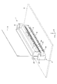
- FIG. 1 is a perspective view of a connector and a cable according to the embodiment.
- FIG. 2 is a perspective view of the connector according to the embodiment.
- FIG. 3 is a perspective view of the connector and cable of the embodiment.
- FIG. 4 is a perspective view of the connector according to the embodiment.
- FIG. 5 is a left side view of the connector and cable of the embodiment.
- FIG. 6 is a plan view of the connector and cable of the embodiment.
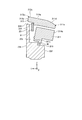
- 7 is a cross-sectional view taken along the line AA in FIG.
- FIG. 8 is a plan view of the side wall with the actuator properly closed.
- FIG. 9 is a plan view of the side wall with the actuator not properly closed.
- 10 is a cross-sectional view taken along the line BB of FIG.
- FIG. 11 is a perspective view of a modified connector.
- FIG. 12 is a cross-sectional view of a modified connector.
- FIG. 1 is a perspective view of a connector and a cable according to the embodiment.
- FIG. 2 is a perspective view of the connector according to the embodiment.
- FIG. 3 is a perspective view of the connector and cable of the embodiment.
- FIG. 4 is a perspective view of the connector according to the embodiment.
- the connector 1 of the embodiment is a device for connecting a cable 8 and a substrate 9.
- the connector 1 is fixed to the substrate 9.
- the cable 8 is a flexible circuit board (Flexible Printed Circuit: FPC) or a flexible flat cable (Flexible Flat Cable: FFC).
- the cable 8 is a flexible thin plate-like cable.
- the board 9 is a printed board and includes a plurality of electronic components.
- an XYZ orthogonal coordinate system is used.
- the Z axis is orthogonal to the substrate 9.
- the X axis is parallel to the longitudinal direction of the connector 1.
- the Y axis is orthogonal to both the X axis and the Z axis.
- the direction along the X axis is described as the X direction
- the direction along the Y axis is described as the Y direction
- the direction along the Z axis is described as the Z direction.
- a direction from the substrate 9 toward the connector 1 in the Z direction is defined as a + Z direction.
- a direction from the cable 8 toward an insulator 2 described later is defined as a + Y direction.
- the + X direction is the right direction when the + Y direction is viewed from the + Y direction.
- a plurality of contacts 4, an insulator 2, and an actuator 3 are provided.
- the plurality of contacts 4 are held by the insulator 2.
- the plurality of contacts 4 are arranged at a predetermined interval in the X direction.
- the contact 4 is fixed to the substrate 9.
- the contact 4 holds the cable 8.
- the contact 4 electrically connects the substrate 9 and the cable 8.
- FIG. 5 is a left side view of the connector and cable of the embodiment.
- FIG. 6 is a plan view of the connector and cable of the embodiment.
- 7 is a cross-sectional view taken along the line AA in FIG.
- the insulator 2 includes two end walls 21 and a rear wall 23.
- the end wall 21 has a plate shape orthogonal to the X axis.
- the rear wall 23 has a plate shape orthogonal to the Y axis.
- the two end walls 21 are connected by a rear wall 23.
- the rear wall 23 includes an upper surface 23a, a first main surface 23c, a back surface 23b, and a front surface 23f.
- the upper surface 23a is a surface that is orthogonal to the Z axis and faces the + Z direction.
- the first major surface 23c is a surface that is orthogonal to the Y axis and faces the -Y direction.
- the first main surface 23 c is a surface facing the cable 8.
- the back surface 23b is a surface that is orthogonal to the Y axis and faces the + Y direction.
- the back surface 23b is a surface opposite to the first main surface 23c.
- the front surface 23f is a surface that is orthogonal to the Y axis and faces the -Y direction.
- the front surface 23f is the surface farthest from the back surface 23b.
- the rear wall 23 includes two recesses 235.
- the recess 235 is a groove provided in the upper surface 23a.
- Actuator 3 is attached to insulator 2.
- the actuator 3 can rotate with respect to the insulator 2.
- the actuator 3 rotates around the rotation axis R shown in FIG.
- the rotation axis R is parallel to the X axis. That is, the rotation axis R is parallel to the substrate 9.
- the actuator 3 includes two side walls 31, a first plate 33, and a second plate 34.
- the side wall 31 has a plate shape orthogonal to the X axis.
- the first plate 33 has a plate shape orthogonal to the side wall 31.
- the second plate 34 has a plate shape orthogonal to the side wall 31 and the first plate 33.
- the two side walls 31 are connected by a first plate 33 and a second plate 34. The first plate 33 and the second plate 34 improve the strength of the actuator 3.
- the two side walls 31 When viewed from the Z direction, the two side walls 31 are arranged at positions displaced from the contacts 4. That is, the two side walls 31 do not overlap the contact 4 in plan view.
- the side wall 31 on the + X direction side is located in the + X direction with respect to the contact 4 located at the end on the + X direction side among the plurality of contacts 4.
- the side wall 31 on the ⁇ X direction side is located in the ⁇ X direction with respect to the contact 4 located at the end on the ⁇ X direction side among the plurality of contacts 4.
- the side wall 31 includes a base portion 311, a shaft 319, a recognition portion 313, and a convex portion 315.
- the base 311 includes an upper surface 311a, a second main surface 311c, a second end surface 311b, a curved surface 311d, and a second ridgeline 311e.
- the second main surface 311c is a surface that faces the first main surface 23c when the actuator 3 is rotated in a direction approaching the cable 8.
- the second end surface 311b is a surface located on the opposite side to the second main surface 311c.
- the second end surface 311b is parallel to the second main surface 311c.
- the curved surface 311d connects the second end surface 311b and the upper surface 311a. When viewed from the X direction, the curved surface 311d draws an arc centered on the rotation axis R.
- the second ridge line 311e is formed at a position where the curved surface 311d and the second end surface 311b intersect. That is, the second ridge line 311e is located at the end of the curved surface 311d and the end of the second end surface 311b.
- a state in which the second main surface 311c is parallel to the first main surface 23c is described as a first state.
- the state in which the second main surface 311c is orthogonal to the first main surface 23c is described as a second state.
- FIG. 2 and FIGS. 5 to 7 show the first state.
- the first state can also be said to be a state in which the actuator 3 is closed. 3 and 4 show the second state.
- the second state can also be said to be a state where the actuator 3 is opened.
- the cable 8 can be inserted between the insulator 2 and the actuator 3. After the cable 8 is inserted between the insulator 2 and the actuator 3, the actuator 3 is rotated in a direction approaching the cable 8.
- the actuator 3 rotates to a predetermined position, the actuator 3 is positioned by a lock mechanism provided in the insulator 2.
- the upper surface 311a of the base 311 is orthogonal to the Z axis and faces the + Z direction.
- the second main surface 311c of the base 311 is orthogonal to the Y axis and faces the + Y direction.
- the second main surface 311 c faces the ear portion 81 of the cable 8.
- the second end surface 311b of the base 311 is orthogonal to the Y axis and faces the ⁇ Y direction.
- the second ridge line 311e is located at the end of the side wall 31 in the ⁇ Y direction.
- the distance L5 is larger than the distance L6.
- the distance L5 is a distance from the rotation axis R to the second end surface 311b in a direction orthogonal to the second main surface 311c (Y direction in the first state shown in FIG. 7).
- the distance L6 is a distance from the rotation axis R to the front surface 23f.
- the shaft 319 projects from the base 311 in the X direction.
- the shaft 319 is attached to the end wall 21 of the insulator 2.
- the actuator 3 rotates around the shaft 319.
- the rotation axis R is a straight line passing through the center of a cross section obtained by cutting the shaft 319 along a plane orthogonal to the X axis.
- the recognition part 313 protrudes from the base 311 in a direction orthogonal to the second main surface 311c.
- the recognition unit 313 protrudes from the base 311 in the + Y direction.
- the recognition unit 313 is positioned in the + Y direction with respect to the first main surface 23 c of the insulator 2 and fits into the recess 235.
- the recognition unit 313 protrudes from the back surface 23b of the insulator 2 in the + Y direction.
- the recognition unit 313 includes an upper surface 313a, a first end surface 313b, and a first ridge line 313e.
- the upper surface 313a is a surface on the side opposite to the rear wall 23 of the insulator 2 and has a planar shape.
- the upper surface 313a is connected to the upper surface 311a of the base 311.
- the first end surface 313b is a surface farthest from the rotation axis R in a direction orthogonal to the second main surface 311c.
- the angle formed by the upper surface 313a and the first end surface 313b is 90 °.
- the first ridge line 313e is formed at a position where the upper surface 313a and the first end surface 313b intersect.
- the first ridge line 313e is located at the end of the upper surface 313a and the end of the first end surface 313b.
- the distance from the second end surface 311b to the first end surface 313b (the length in the Y direction of the side wall 31 in the first state) is larger than the length in the Y direction of the end wall 21 of the insulator 2.
- the distance from the second end surface 311b to the first end surface 313b is desirably as large as possible.
- the upper surface 313a is orthogonal to the Z axis and faces the + Z direction.
- the first end face 313b is orthogonal to the Y axis and faces the + Y direction.
- the first ridge line 313e is located at the end of the side wall 31 in the + Y direction.
- the distance L1 is larger than the distance L2.
- the distance L1 is a distance from the rotation axis R to the tip of the recognition unit 313 (first end surface 313b) in a direction orthogonal to the second main surface 311c (Y direction in the first state shown in FIG. 7).
- the distance L2 is a distance from the rotation axis R to the back surface 23b.
- the upper surface 313a of the recognition unit 313 is displaced in the Z direction with respect to the upper surface 23a of the insulator 2.
- the distance L3 is larger than the distance L4.
- the distance L3 is from the rotation axis R in the direction orthogonal to the rotation axis R and parallel to the second main surface 311c (Z direction in the first state shown in FIG. 7) to the tip of the recognition unit 313 (upper surface 313a).
- the distance L4 is a distance from the rotation axis R to the upper surface 23a of the rear wall 23 in a direction perpendicular to the rotation axis R and parallel to the back surface 23b (Z direction in the first state shown in FIG. 7).
- the convex portion 315 protrudes from the base portion 311 in a direction orthogonal to the second main surface 311 c.
- the convex portion 315 In the first state, the convex portion 315 is located in the ⁇ Y direction with respect to the first main surface 23 c of the insulator 2 and is located in the ⁇ Z direction with respect to the concave portion 235.
- the convex portion 315 faces the first main surface 23c with a gap.
- the convex portion 315 covers the + Z direction side of the ear portion 81 of the cable 8. Thereby, the cable 8 is prevented from coming off.
- the first plate 33 is a member extending from one side wall 31 to the other side wall 31.
- the first plate 33 has a plate shape orthogonal to the second main surface 311c.
- the first plate 33 In the first state, the first plate 33 has a plate shape orthogonal to the Z axis.
- the first plate 33 includes a notch 331.
- the notch 331 overlaps at least one of the contacts 4 in the Z direction in the first state. Thereby, it becomes possible to confirm the mounting state of the contact 4 from the Z direction.
- the second plate 34 is a member extending from one side wall 31 to the other side wall 31.
- the second plate 34 has a plate shape orthogonal to the first plate 33.
- the second plate 34 In the first state, has a plate shape orthogonal to the Y axis.
- the first plate 33 and the second plate 34 improve the strength of the actuator 3.
- FIG. 8 is a plan view of the side wall with the actuator properly closed.
- FIG. 9 is a plan view of the side wall with the actuator not properly closed.
- 10 is a cross-sectional view taken along the line BB of FIG. 1 and 5 to 8 show a state in which the actuator 3 is correctly closed.
- the state in which the actuator 3 is properly closed is a state in which the convex portion 315 of the side wall 31 is positioned in the + Z direction with respect to the ear portion 81 of the cable 8 as shown in FIG.
- the state where the actuator 3 is not properly closed is a state where the convex portion 315 rides on the ⁇ Y direction of the ear portion 81 as shown in FIG.
- the actuator 3 may not be properly closed due to interference between the actuator 3 and the ear 81 of the cable 8 or the like.
- the actuator 3 that is not properly closed needs to be detected by product inspection or the like. For this reason, it is desirable that the connector 1 can easily determine whether or not the actuator 3 is properly closed by inspection.
- the convex portion 315 of the side wall 31 is positioned in the + Z direction with respect to the ear portion 81 of the cable 8 as shown in FIG.
- the second main surface 311c is parallel to the first main surface 23c.
- the recognition unit 313 protrudes in the + Y direction from the back surface 23 b of the insulator 2.
- the convex portion 315 of the side wall 31 interferes with the ear portion 81 of the cable 8. That is, the convex portion 315 rides on the ear portion 81 in the ⁇ Y direction.
- the second main surface 311c is not parallel to the first main surface 23c.
- the recognition unit 313 does not protrude from the back surface 23 b of the insulator 2. Or even if the recognition part 313 protrudes in + Y direction rather than the back surface 23b, compared with the case of FIG. 8, the protrusion amount becomes small.
- the connector 1 is automatically inspected by an inspection device.
- the inspection device is, for example, an automatic optical inspection device (AOI).
- the inspection apparatus scans the connector 1 with the camera from the + Z direction side.
- the inspection device determines whether or not the cable 8 is correctly connected based on the position of the recognition unit 313. For example, the inspection apparatus detects the position of the first ridge line 313e of the recognition unit 313 with respect to a predetermined reference line S1, as shown in FIGS.
- the reference line S1 is a straight line that overlaps the back surface 23b of the insulator 2, for example.
- the inspection apparatus determines that the cable 8 is correctly connected.
- FIG. 9 when the first ridge line 313e is located on the ⁇ Y direction side of the reference line S1, the inspection apparatus determines that the cable 8 is not correctly connected.
- the reference line S1 is not necessarily a straight line that overlaps the back surface 23b.
- the position of the reference line S1 is not particularly limited.
- the inspection apparatus may detect the protrusion amount of the recognition unit 313 with respect to the reference line S1. The inspection apparatus may determine whether or not the cable 8 is correctly connected based on the area occupied by the recognition unit 313 in an arbitrary region A1 as illustrated in FIGS.
- the inspection device determines whether the cable 8 is correctly connected based on the position of the base 311. For example, the inspection apparatus detects the position of the second ridge line 311e of the base 311 with respect to a predetermined reference line S2, as shown in FIGS. As shown in FIG. 8, when the second ridge line 311e is located on the + Y direction side of the reference line S1, the inspection apparatus determines that the cable 8 is correctly connected. As shown in FIG. 9, when the second ridge line 311e is located on the ⁇ Y direction side of the reference line S2, the inspection apparatus determines that the cable 8 is not correctly connected.
- the inspection apparatus may detect the protruding amount of the base 311 with respect to the reference line S2.
- the inspection apparatus may determine whether or not the cable 8 is correctly connected based on the area occupied by the base 311 in an arbitrary region A2 as shown in FIGS.
- the insulator 2 does not necessarily have to include the recess 235. However, it is desirable that the insulator 2 includes the recess 235 in that the recognition unit 313 is less likely to be displaced in the X direction from a predetermined position. Since the recognition unit 313 is positioned by the recess 235, the determination accuracy of the inspection apparatus is improved.
- the second end surface 311b may not be parallel to the second main surface 311c.
- the angle which the 2nd end surface 311b makes with respect to the upper surface 311a should just be 90 degrees or less.
- the angle formed between the upper surface 313a and the first end surface 313b may not be 90 °, but may be 90 ° or less.
- the two side walls 31 may overlap the contact 4 in plan view. However, it is preferable that the two side walls 31 do not overlap with the contact 4 in plan view in that it is easy to check the mounting state of the contact 4.
- the connector 1 may include an elastic member that pushes the actuator 3 away from the insulator 2.
- the elastic member is, for example, a spring formed of metal.
- the connector 1 includes the insulator 2, the contact 4, and the actuator 3.
- the insulator 2 includes a first main surface 23c that is a surface facing the cable 8, and a back surface 23b that is a surface opposite to the first main surface 23c.
- the contact 4 electrically connects the cable 8 and the substrate 9.
- the actuator 3 can rotate around a rotation axis R parallel to the substrate 9.
- the actuator 3 includes a plate-like side wall 31 that intersects the rotation axis R.
- the side wall 31 includes a base 311 provided with a second main surface 311c that is a surface facing the first main surface 23c when the actuator 3 is rotated in a direction approaching the cable 8, and a recognition unit 313 protruding from the base 311. Is provided.
- a distance L1 from the rotation axis R to the tip (first end surface 313b) of the recognition unit 313 in a direction orthogonal to the second main surface 311c is larger than a distance L2 from the rotation axis R to the back surface 23b.
- the recognition unit 313 protrudes from the insulator 2 in a plan view.
- the recognition unit 313 does not protrude from the insulator 2 in a plan view, or the amount of protrusion of the recognition unit 313 is small. Therefore, according to the connector 1, it can be easily determined by inspection whether or not the actuator 3 is properly closed.
- a distance L3 from the rotation axis R to the tip (upper surface 313a) of the recognition unit 313 in a direction orthogonal to the rotation axis R and parallel to the second main surface 311c is orthogonal to the rotation axis R.
- the distance L4 from the rotation axis R to the upper surface 23a of the insulator 2 in a direction parallel to the rear surface 23b is different.
- a distance L3 from the rotation axis R to the tip (upper surface 313a) of the recognition unit 313 in a direction orthogonal to the rotation axis R and parallel to the second main surface 311c is orthogonal to the rotation axis R.
- the distance L4 is larger than the distance L4 from the rotation axis R to the upper surface 23a of the insulator 2 in the direction parallel to the rear surface 23b.
- the recognition unit 313 includes a first end surface 313b that is a surface farthest from the rotation axis R in a direction orthogonal to the second main surface 311c, and a first ridge line 313e that is positioned at the end of the first end surface 313b. And comprising. Thereby, the position of the front-end
- the recognition unit 313 includes a top surface 313a that is a surface opposite to the insulator 2 and is planar. Thereby, the reflection in the recognition part 313 of the light irradiated from an inspection apparatus tends to become uniform. For this reason, according to the connector 1, it becomes easier to check whether or not the actuator 3 is properly closed.
- the insulator 2 includes a front surface 23f that is the surface farthest from the back surface 23b.
- the base 311 includes a second end surface 311b which is a surface located on the opposite side of the rotation axis R from the second main surface 311c.
- a distance L5 from the rotation axis R to the second end surface 311b in a direction orthogonal to the second main surface 311c is larger than a distance L6 from the rotation axis R to the front surface 23f.
- the connector 1 includes an insulator 2, a contact 4, and an actuator 3.
- the insulator 2 includes a first main surface 23c that is a surface facing the cable 8, a back surface 23b that is a surface opposite to the first main surface 23c, and a front surface 23f that is a surface farthest from the back surface 23b.
- the contact 4 electrically connects the cable 8 and the substrate 9.
- the actuator 3 can rotate around a rotation axis R parallel to the substrate 9.
- the actuator 3 includes a plate-like side wall 31 that intersects the rotation axis R.
- the side wall 31 is opposite to the second main surface 311c with respect to the rotation axis R and the second main surface 311c, which is the surface facing the first main surface 23c when the actuator 3 is rotated in the direction approaching the cable 8. And a second end face 311b which is a surface located on the side.
- a distance L5 from the rotation axis R to the second end surface 311b in a direction orthogonal to the second main surface 311c is larger than a distance L6 from the rotation axis R to the front surface 23f.
- the base 311 protrudes from the insulator 2 in a plan view.
- the actuator 3 is not properly closed, the base 311 does not protrude from the insulator 2 in a plan view or the protruding amount of the recognition unit 313 becomes small. Therefore, according to the connector 1, it can be easily determined by inspection whether or not the actuator 3 is properly closed.
- the base 311 includes a second ridgeline 311e located at the end of the second end surface 311b. Thereby, the position of the front-end
- the base 311 includes a curved surface 311d connected to the second end surface 311b.
- the curved surface 311d draws an arc centered on the rotation axis R.
- the curved surface 311d is an arc centered on the rotation axis R, so that the position from the camera to the photographing target portion is constant even if the actuator 3 is tilted to some extent. For this reason, even if the focus position of the camera is constant, the captured image tends to be clear. Therefore, the inspection accuracy as to whether or not the actuator 3 is properly closed is improved.
- FIG. 11 is a perspective view of a modified connector.
- FIG. 12 is a cross-sectional view of a modified connector. Note that the same components as those described in the above-described embodiment are denoted by the same reference numerals, and redundant description is omitted.
- the actuator 3A of the connector 1A includes a side wall 31A having a shape different from that of the side wall 31 described above.
- the base 311A of the side wall 31A includes a curved surface 311dA.
- the curved surface 311dA connects the second end surface 311b and the upper surface 311a.
- the base 311A does not include the second ridge line 311e described above at the end of the curved surface 311dA. That is, the curved surface 311dA and the second end surface 311b are smoothly connected.
- the base 311A may not include the second ridge line 311e. Even in such a case, the base 311A can be used for checking whether the actuator 3 is properly closed.
Landscapes
- Details Of Connecting Devices For Male And Female Coupling (AREA)
- Coupling Device And Connection With Printed Circuit (AREA)
Abstract
L'invention concerne un connecteur comprenant : un isolant qui a une première surface principale qui fait face à un câble et une surface arrière qui est sur le côté opposé de la première surface principale ; un contact qui connecte électriquement le câble et un substrat l'un à l'autre ; et un actionneur qui est apte à tourner autour d'un axe de rotation qui est parallèle au substrat. L'actionneur comprend une paroi latérale en forme de plaque qui croise l'axe de rotation. La paroi latérale comprend : une partie de base qui a une seconde surface principale qui fait face à la première surface principale lorsque l'actionneur est tourné dans une direction s'approchant du câble ; et une partie de reconnaissance qui fait saillie à partir de la partie de base. La distance de l'axe de rotation à l'extrémité avant de la partie de reconnaissance est supérieure à la distance de l'axe de rotation à la surface arrière dans la direction qui est perpendiculaire à la seconde surface principale.
Priority Applications (4)
| Application Number | Priority Date | Filing Date | Title |
|---|---|---|---|
| KR1020207024522A KR102390861B1 (ko) | 2018-02-26 | 2019-02-07 | 커넥터 |
| US16/975,569 US11245211B2 (en) | 2018-02-26 | 2019-02-07 | Connector having an actuator |
| CN201980012860.8A CN111712972B (zh) | 2018-02-26 | 2019-02-07 | 连接器 |
| EP19757344.7A EP3761457B1 (fr) | 2018-02-26 | 2019-02-07 | Connecteur |
Applications Claiming Priority (2)
| Application Number | Priority Date | Filing Date | Title |
|---|---|---|---|
| JP2018-032234 | 2018-02-26 | ||
| JP2018032234A JP6552659B1 (ja) | 2018-02-26 | 2018-02-26 | コネクタ |
Publications (1)
| Publication Number | Publication Date |
|---|---|
| WO2019163539A1 true WO2019163539A1 (fr) | 2019-08-29 |
Family
ID=67473246
Family Applications (1)
| Application Number | Title | Priority Date | Filing Date |
|---|---|---|---|
| PCT/JP2019/004484 Ceased WO2019163539A1 (fr) | 2018-02-26 | 2019-02-07 | Connecteur |
Country Status (6)
| Country | Link |
|---|---|
| US (1) | US11245211B2 (fr) |
| EP (1) | EP3761457B1 (fr) |
| JP (1) | JP6552659B1 (fr) |
| KR (1) | KR102390861B1 (fr) |
| CN (1) | CN111712972B (fr) |
| WO (1) | WO2019163539A1 (fr) |
Citations (5)
| Publication number | Priority date | Publication date | Assignee | Title |
|---|---|---|---|---|
| JPH01315976A (ja) * | 1988-05-05 | 1989-12-20 | Amp Inc | 無挿入力電気コネクタ |
| US5795172A (en) * | 1996-12-18 | 1998-08-18 | Intel Corporation | Production printed circuit board (PCB) edge connector test connector |
| JP2005005210A (ja) * | 2003-06-13 | 2005-01-06 | Taiko Denki Co Ltd | 縦型コネクタ |
| JP2005135679A (ja) * | 2003-10-29 | 2005-05-26 | Taiko Denki Co Ltd | 扁平導体用コネクタ |
| JP2014026765A (ja) * | 2012-07-25 | 2014-02-06 | Molex Inc | コネクタ |
Family Cites Families (13)
| Publication number | Priority date | Publication date | Assignee | Title |
|---|---|---|---|---|
| US6790074B1 (en) * | 2003-03-14 | 2004-09-14 | P-Two Industries Inc. | Electrical power connector for flexible circuit board |
| TWM288981U (en) * | 2005-06-28 | 2006-03-21 | Compal Electronics Inc | Connector |
| JP4542525B2 (ja) * | 2005-07-07 | 2010-09-15 | 山一電機株式会社 | ケーブル用コネクタ |
| US20070054558A1 (en) * | 2005-09-03 | 2007-03-08 | Harlan Tod M | Connector with improved pulling portion |
| JP5020899B2 (ja) * | 2008-06-20 | 2012-09-05 | モレックス インコーポレイテド | 電気コネクタ |
| US7854625B1 (en) * | 2010-06-15 | 2010-12-21 | Cheng Uei Precision Industry Co., Ltd. | Connector for flexible printed circuit board |
| TW201324975A (zh) * | 2011-12-13 | 2013-06-16 | Aces Electronic Co Ltd | 電連接器 |
| JP2013178892A (ja) * | 2012-02-28 | 2013-09-09 | Kyocera Connector Products Corp | ケーブル用コネクタ |
| JP5571837B1 (ja) * | 2013-08-21 | 2014-08-13 | イリソ電子工業株式会社 | 電気コネクタ |
| US9680244B1 (en) * | 2014-09-09 | 2017-06-13 | Universal Lighting Technologies, Inc | Header apparatus for providing electrical connection to a printed circuit board, and daughter card and circuit assembly incorporating the header apparatus |
| JP6282565B2 (ja) * | 2014-09-22 | 2018-02-21 | 京セラ株式会社 | ケーブル用コネクタ |
| JP6336941B2 (ja) * | 2015-04-01 | 2018-06-06 | モレックス エルエルシー | コネクタ及びその製造方法 |
| JP6308197B2 (ja) * | 2015-11-10 | 2018-04-11 | 第一精工株式会社 | 電気コネクタ |
-
2018
- 2018-02-26 JP JP2018032234A patent/JP6552659B1/ja active Active
-
2019
- 2019-02-07 US US16/975,569 patent/US11245211B2/en active Active
- 2019-02-07 KR KR1020207024522A patent/KR102390861B1/ko active Active
- 2019-02-07 WO PCT/JP2019/004484 patent/WO2019163539A1/fr not_active Ceased
- 2019-02-07 CN CN201980012860.8A patent/CN111712972B/zh active Active
- 2019-02-07 EP EP19757344.7A patent/EP3761457B1/fr active Active
Patent Citations (5)
| Publication number | Priority date | Publication date | Assignee | Title |
|---|---|---|---|---|
| JPH01315976A (ja) * | 1988-05-05 | 1989-12-20 | Amp Inc | 無挿入力電気コネクタ |
| US5795172A (en) * | 1996-12-18 | 1998-08-18 | Intel Corporation | Production printed circuit board (PCB) edge connector test connector |
| JP2005005210A (ja) * | 2003-06-13 | 2005-01-06 | Taiko Denki Co Ltd | 縦型コネクタ |
| JP2005135679A (ja) * | 2003-10-29 | 2005-05-26 | Taiko Denki Co Ltd | 扁平導体用コネクタ |
| JP2014026765A (ja) * | 2012-07-25 | 2014-02-06 | Molex Inc | コネクタ |
Non-Patent Citations (1)
| Title |
|---|
| See also references of EP3761457A4 * |
Also Published As
| Publication number | Publication date |
|---|---|
| US11245211B2 (en) | 2022-02-08 |
| US20200403339A1 (en) | 2020-12-24 |
| CN111712972A (zh) | 2020-09-25 |
| KR102390861B1 (ko) | 2022-04-26 |
| JP2019149253A (ja) | 2019-09-05 |
| EP3761457B1 (fr) | 2024-01-03 |
| EP3761457A4 (fr) | 2021-11-24 |
| EP3761457A1 (fr) | 2021-01-06 |
| KR20200110434A (ko) | 2020-09-23 |
| CN111712972B (zh) | 2021-12-28 |
| JP6552659B1 (ja) | 2019-07-31 |
Similar Documents
| Publication | Publication Date | Title |
|---|---|---|
| US20100134615A1 (en) | Shape measurement apparatus and shape measurement method | |
| US20230180416A1 (en) | Sensor provided with plurality of circuit boards | |
| JP2006210205A (ja) | モジュール用ソケット | |
| US10806333B2 (en) | Three-dimensional wiring substrate and imaging unit | |
| CN115066875B (zh) | 包括印刷电路板的电子装置 | |
| JP6552659B1 (ja) | コネクタ | |
| EP3355420B1 (fr) | Structure de borne étanche à l'eau, module de dispositif électronique et utilisation du module de dispositif électronique | |
| US10608360B2 (en) | Circuit board-mounted electrical connector | |
| US20040246232A1 (en) | Optic mouse | |
| US7165991B2 (en) | Connector | |
| JP2012037336A (ja) | 検査装置 | |
| JP6949643B2 (ja) | 照明装置及び表示装置 | |
| KR102340537B1 (ko) | 멀티 카메라 모듈 | |
| JP2002270984A (ja) | カメラ内に配設されるフレキシブル基板の接続構造 | |
| JP2018097179A (ja) | 電子機器、及び撮像装置 | |
| US12603449B2 (en) | Connection structure and electronic substrate | |
| US20250147555A1 (en) | Electronic device and production method for electronic device | |
| US12566337B2 (en) | Optical unit with shake correction function | |
| KR20030071533A (ko) | 위치검출방법, 위치검출장치 및 프린트 기판의 위치결정방법 | |
| JP2021039830A (ja) | コネクタ | |
| JP2019153540A (ja) | コネクタ | |
| TWI584053B (zh) | Aperture devices and cameras | |
| JP2014048122A (ja) | 情報取得装置および物体検出装置 | |
| JP2009264784A (ja) | 測距センサ | |
| JP2004349297A (ja) | ジャック基板位置決め機構 |
Legal Events
| Date | Code | Title | Description |
|---|---|---|---|
| 121 | Ep: the epo has been informed by wipo that ep was designated in this application |
Ref document number: 19757344 Country of ref document: EP Kind code of ref document: A1 |
|
| ENP | Entry into the national phase |
Ref document number: 20207024522 Country of ref document: KR Kind code of ref document: A |
|
| NENP | Non-entry into the national phase |
Ref country code: DE |
|
| ENP | Entry into the national phase |
Ref document number: 2019757344 Country of ref document: EP Effective date: 20200928 |