WO2019167662A1 - Embrayage électromagnétique - Google Patents
Embrayage électromagnétique Download PDFInfo
- Publication number
- WO2019167662A1 WO2019167662A1 PCT/JP2019/005506 JP2019005506W WO2019167662A1 WO 2019167662 A1 WO2019167662 A1 WO 2019167662A1 JP 2019005506 W JP2019005506 W JP 2019005506W WO 2019167662 A1 WO2019167662 A1 WO 2019167662A1
- Authority
- WO
- WIPO (PCT)
- Prior art keywords
- slit
- long
- electromagnetic clutch
- short
- row
- Prior art date
- Legal status (The legal status is an assumption and is not a legal conclusion. Google has not performed a legal analysis and makes no representation as to the accuracy of the status listed.)
- Ceased
Links
Images




Classifications
-
- F—MECHANICAL ENGINEERING; LIGHTING; HEATING; WEAPONS; BLASTING
- F16—ENGINEERING ELEMENTS AND UNITS; GENERAL MEASURES FOR PRODUCING AND MAINTAINING EFFECTIVE FUNCTIONING OF MACHINES OR INSTALLATIONS; THERMAL INSULATION IN GENERAL
- F16D—COUPLINGS FOR TRANSMITTING ROTATION; CLUTCHES; BRAKES
- F16D27/00—Magnetically- or electrically- actuated clutches; Control or electric circuits therefor
- F16D27/10—Magnetically- or electrically- actuated clutches; Control or electric circuits therefor with an electromagnet not rotating with a clutching member, i.e. without collecting rings
- F16D27/108—Magnetically- or electrically- actuated clutches; Control or electric circuits therefor with an electromagnet not rotating with a clutching member, i.e. without collecting rings with axially movable clutching members
- F16D27/112—Magnetically- or electrically- actuated clutches; Control or electric circuits therefor with an electromagnet not rotating with a clutching member, i.e. without collecting rings with axially movable clutching members with flat friction surfaces, e.g. discs
Definitions
- the present invention relates to an electromagnetic clutch.
- a gas compressor of an air conditioning system (hereinafter referred to as an air conditioning system) mounted on a vehicle or the like operates by receiving power from a power source (such as an engine) of the vehicle.
- a power source such as an engine
- an electromagnetic clutch is used to connect and disconnect the power supply from the power source.
- the electromagnetic clutch includes a rotor, an electromagnetic coil, and an armature. The rotor always rotates under the power of the power source, and the armature is connected to the rotating shaft of the gas compressor.
- the electromagnetic coil is disposed inside a space formed in the rotor.
- the armature does not rotate because it is separated from the rotating rotor by a certain gap in the axial direction.
- the armature accommodates the electromagnetic coil by the magnetic force. It is sucked by the rotor and displaced or deformed in the axial direction.
- the friction surface of the armature (perpendicular to the axial direction) and the friction surface of the rotor (perpendicular to the axial direction) come into contact with each other, and the armature rotates integrally with the rotor by the friction force generated on both friction surfaces.
- the rotating shaft connected to the motor rotates.
- an elastic force of a spring member or the like acts on the armature, and when the electromagnetic coil is de-energized, there is no magnetic force for attracting the armature, and the armature is returned to a state separated from the rotor by this elastic force.
- the electromagnetic clutch is connected / disconnected to / from the power source depending on whether or not voltage is applied to the electromagnetic coil.
- noise may be generated.
- This squeaking noise is said to be affected by an arcuate slit formed in the rotor end plate on which the friction surface of the rotor is formed, extending in the axial direction and extending in the circumferential direction around the axis.
- production of a squeal is prevented is performed (for example, refer patent document 1).
- positioning of a slit there exist a thing which has eight bridge parts, a thing which has six bridge parts, a thing which has four bridge parts, etc., for example.
- the difference in rigidity in the rotation direction of the rotor affects the generation of squeal.
- the arrangement of the slits having eight bridge portions is likely to generate a squeal, and the squeal may be a problem even with the arrangement of slits having six bridge portions.
- the present invention has been made in view of the above circumstances, and an object thereof is to provide an electromagnetic clutch capable of preventing or suppressing the generation of squeal and suppressing magnetic flux leakage while ensuring strength.
- the present invention includes a rotor having an end plate in which an annular electromagnetic coil is accommodated and formed with a slit array extending along a circumference around the center of the annular ring, and the electromagnetic coil according to the magnetic force of the electromagnetic coil.
- An armature connected to an end plate, and the slit row is arranged so that a relatively long slit and a short slit are arranged in at least a part along the circumference, and the slit
- the row is an electromagnetic clutch arranged so as not to overlap at least partially with the slit row in a state where the end plate is rotated at an angle of 45 degrees around the center.
- the electromagnetic clutch according to the present invention it is possible to prevent or suppress the generation of squeal and to suppress magnetic flux leakage while ensuring the strength.
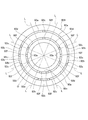
- FIG. 3 is a view corresponding to FIG. 2, illustrating a state in which the end plate illustrated in FIG. 2 is rotated by an angle of 45 ° around the axis.
- FIG. 3 is a side view corresponding to FIG. 2 showing an end plate of a modified example in which a slit row in which long slits are arranged at an angular interval of 120 [°] around the axis is formed.
- the radially outer slit row is arranged so that long slits and short slits are alternately arranged, and the radially inner slit row shows a modified end plate in which only slits of a certain length are arranged side by side.
- FIG. 3 is a side view corresponding to FIG. 2. It is a figure which shows the end plate of the example in which long slits were located in a part of the circumferential direction, and the outer side slit row
- column show the form which each has five slits.
- the ratio between the length of the long slit and the length of the short slit in the outer slit row is formed in different phase ranges from the long slit and the short slit in the outer slit row and the long slit and the short slit in the inner slit row.
- the ratio between the length of the long slit and the length of the short slit in the outer slit row is formed in different phase ranges from the long slit and the short slit in the outer slit row and the long slit and the short slit in the inner slit row.
- FIG. 1 is a cross-sectional view of an essential part showing a compressor 100 having an electromagnetic clutch 90 according to an embodiment of the present invention.
- the illustrated compressor 100 is, for example, a vane rotary type gas compressor.
- a compressor 100 shown in FIG. 1 is configured as a part of an air conditioning system (hereinafter simply referred to as an air conditioning system) that is mounted on a vehicle and performs cooling using the heat of vaporization of a cooling medium.
- An air conditioning system hereinafter simply referred to as an air conditioning system
- the compressor 100 compresses the refrigerant gas G (gas) as a gaseous cooling medium taken from the evaporator of the air conditioning system, and supplies the compressed refrigerant gas to the condenser of the air conditioning system.
- the condenser heat-exchanges the compressed refrigerant gas with ambient air or the like to dissipate heat from the refrigerant gas and liquefy it, and sends it to the expansion valve as a high-pressure liquid refrigerant.
- the high-pressure liquid refrigerant is reduced in pressure by the expansion valve and sent to the evaporator.
- the low-pressure liquid refrigerant absorbs heat from the surrounding air and vaporizes in the evaporator, and cools the air around the evaporator by heat exchange accompanying the vaporization of the refrigerant.
- the vaporized low-pressure refrigerant gas G returns to the compressor 100 and is compressed, and the above process is repeated thereafter.
- the compressor 100 sucks low-pressure refrigerant gas G into the interior, compresses the compressed gas into high pressure, and discharges it.
- the housing 10 that houses the compression mechanism 60 therein, and the compression mechanism 60 are driven.
- an electromagnetic clutch 90 for connecting and disconnecting power supply from an external power source.
- the housing 10 includes a case 11 whose one end is closed and a front head 12 which covers the opened end of the case 11.
- a space for accommodating the compression mechanism 60 is formed inside the housing 10 with the front head 12 covering the end of the case 11.
- the compression mechanism section 60 has a rotating shaft 51 lubricated with the refrigerating machine oil R. When the rotating shaft 51 rotates, the low-pressure refrigerant gas G is sucked into the interior, compressed to a high pressure, and discharged to the outside. To do.
- one end 51a of the rotating shaft 51 is exposed to the outside of the housing 10. Specifically, in the state shown in FIG. 2, the left end 51 a of the rotating shaft is exposed to the outside of the front head 12.
- the electromagnetic clutch 90 includes a pulley 91, a rotor 92, an electromagnetic coil 93, and an armature 94.
- the pulley 91 has a belt wound around an outer peripheral surface 91a in which a plurality of grooves having a V-shaped cross section along the circumferential direction are formed. This belt is supplied with power from an engine (an example of a power source) of a vehicle on which the compressor 100 is mounted.
- the rotor 92 is integrated with the pulley 91. Accordingly, when the pulley 91 is supplied with power from an engine or the like, the pulley 91 and the rotor 92 rotate around the axis O as a unit.
- the electromagnetic coil 93 is fixed to the front head 12 via a yoke, does not rotate around the axis O, generates a magnetic force when energized, and disappears when the energization is stopped.
- the armature 94 includes a hub 94b, an outer ring 94a, and a leaf spring 94c.
- the hub 94b is fastened to the end 51a of the rotating shaft 51 exposed from the front head 12 by a screw 70.
- the outer ring 94a is arranged so as to protrude outward in the radial direction from the hub 94b.
- the leaf spring 94c connects the hub 94b and the outer ring 94a so that the outer ring 94a can be displaced with respect to the hub 94b by elastic deformation of the leaf spring 94c along the direction in which the axis O extends. It has become.
- the outer ring 94a is disposed through a slight gap with the end plate 92A of the rotor 92.
- the electromagnetic coil 93 When the electromagnetic coil 93 generates a magnetic force by energizing the electromagnetic coil 93, the outer ring 94a is attracted by the magnetic force, The plate spring 94c is displaced to a position in contact with the end plate 92A in the direction of the axis O against the elastic force of the leaf spring 94c.
- the outer ring 94a of the armature 94 contacts the end plate 92A of the rotor 92, and the armature 94 rotates along with the rotating rotor 92 by the frictional force, and the rotating shaft 51 connected to the armature 94 is rotated. Rotate.
- the magnetic force generated by the electromagnetic coil 93 disappears, and the outer ring 94a that is in contact with the end plate 92A of the rotor 92 is moved by the elastic force of the leaf spring 94c to the end plate 92A.
- the armature 94 stops and the compression mechanism part 60 of the compressor 100 also stops.
- the armature 94 is connected to the end plate 92 ⁇ / b> A according to the magnetic force generated by the electromagnetic coil 93.
- the rotor 92 is fixed to the front head 12 via a radial bearing, and is rotatable around the rotation axis O.
- the rotor 92 is formed with an annular coil housing space 92B in which an annular electromagnetic coil 93 centered on the axis O is accommodated.
- the rotor 92 has an end plate 92 ⁇ / b> A having a friction surface with which the armature 94 comes into contact at an end portion in the axial direction on the side close to the armature 94 described later.
- the end plate 92A is formed in a range including a range corresponding to the coil housing space 92B in the radial direction around the axis O.
- FIG. 2 is a view of the end plate 92A of the rotor 92 of the compressor 100 shown in FIG. 1 as viewed from the armature 94 side in the axis O direction.
- 3 is a view corresponding to FIG. 2 and showing a state in which the end plate 92A shown in FIG. 2 is rotated around the axis O by an angle of 45 [°].
- the end plate 92A of the rotor 92 has an outer slit row SL1 extending from the axis O along the circumference of the radius r1 and the circumference of the radius r2 ( ⁇ r1).
- An inner slit row SL2 is formed.
- the slit row SL1 passes through the end plate 92A in the direction of the axis O, and has eight slits 92a, 92b, 92a, 92b, 92a, 92b arranged on the circumference of the radius r1 with the axis O as the center. , 92a, 92b.
- the slit 92a has an arc shape over an angle ⁇ 1 (45 [°] ⁇ 1 ⁇ 90 [°]) around the axis O
- the slit 92b has an angle ⁇ 2 (0 [°] ⁇ 2 ⁇ 45 [°] around the axis O. ) Extending in a circular arc shape.
- the slit 92a is a slit that is relatively long along the circumferential direction with respect to the slit 92b
- the slit 92b is a slit that is relatively short along the circumferential direction with respect to the slit 92a.
- the relatively short slit 92b is formed to have a circumferential length of one third or less of the relatively long slit 92a.
- the relatively long slits 92a and the relatively short slits 92b are arranged alternately along the entire circumference in the circumferential direction.
- a bridge 92c that does not penetrate in the direction of the axis O is formed between the relatively long slit 92a and the relatively short slit 92b.
- the four relatively long slits 92a constituting the slit row SL1 have the same length along the circumferential direction.
- the four relatively short slits 92b constituting the slit row SL1 have the same length along the circumferential direction, and the eight bridges 92c also have the same length along the circumferential direction. It is.
- the four relatively long slits 92a are rotationally symmetric at a multiple of an angle of 90 [°] around the axis O (the same as before rotation when rotated at an angle of 90 [°] around the axis O). It has become.
- the four relatively short slits 92b and the eight bridges 92c are rotationally symmetric at a multiple of an angle of 90 [°] around the axis O. Therefore, the entire slit row SL1 is rotationally symmetric at a multiple of an angle of 90 [°] around the axis O.
- the slit row SL2 also passes through the end plate 92A in the direction of the axis O, and has eight slits 92d, 92e, 92d, 92e, 92d, 92e, 92d, arranged on the circumference of the radius r2 with the axis O as the center. 92e.
- the slit 92d has an arc shape over an angle ⁇ 1 (45 [°] ⁇ 1 ⁇ 90 [°]) around the axis O, and the slit 92e has an angle ⁇ 2 (0 [°] ⁇ 2 ⁇ 45 [°] around the axis O. ) Extending in a circular arc shape.
- the slit 92d is a slit that is relatively long along the circumferential direction with respect to the slit 92e
- the slit 92e is a slit that is relatively short along the circumferential direction with respect to the slit 92d.
- the relatively long slits 92d and the relatively short slits 92e are arranged alternately in the circumferential direction.
- a bridge 92f that does not penetrate in the direction of the axis O is formed between the relatively long slit 92d and the relatively short slit 92e.
- the four relatively long slits 92d constituting the slit row SL2 have the same length along the circumferential direction.
- the four relatively short slits 92e constituting the slit row SL2 have the same length in the circumferential direction
- the eight bridges 92f have the same length in the circumferential direction. It is.
- the four relatively long slits 92d, the four relatively short slits 92e, and the eight bridges 92f are rotationally symmetric at multiples of an angle of 90 ° around the axis O. Therefore, the entire slit row SL2 is rotationally symmetric at a multiple of an angle of 90 [°] around the axis O.
- the long slit 92a of the slit row SL1 and the long slit 92d of the slit row SL2 are formed in the same phase range around the axis O.
- the short slit 92b of the slit row SL1 and the short slit 92e of the slit row SL2 are formed in the same phase range around the axis O
- the bridge 92c of the slit row SL1 and the bridge 92f of the slit row SL2 are They are formed in the same phase range around the center O.
- the ratio L2e / L2d between the length L2d along the length L2e and the length L2e along the circumference of the short slit 92e is a substantially equal ratio (L1b / L1a ⁇ L2e / L2d).
- the slit row SL1 is rotationally symmetric with a multiple of the angle 90 [°] around the axis O, but the angle 45 [°] around the axis O. (Or 135 [°]) is not rotationally symmetric. That is, the end plate 92A shown in FIG. 2 and the end plate 92A shown in FIG. 3 obtained by rotating the end plate 92A shown in FIG. 2 at an angle 45 [°] (or 135 [°]) around the axis O.
- the slit row SL1 does not overlap at least partially.
- the slit 92a of the slit row SL1 before rotating at an angle of 45 [°] and the slit 92a of the slit row SL1 after rotating at an angle of 45 [°] do not completely overlap, and the angle of 45 [°] rotates.
- the slits 92b of the slit row SL1 before the opening and the slits 92b of the slit row SL1 after the angle of 45 [°] do not completely overlap.
- the electromagnetic clutch 90 of the present embodiment has a direction of an angle 45 [°] around the axis O and a direction of an angle 135 [°], and a direction of an angle 0 [°] around the axis O and an angle 90 [°]. ],
- the strength differs due to the difference in rigidity.
- the rigidity (strength) in the direction of the angle 45 [°] around the axis O and the angle 135 [°] The inventors of the present application have found that the difference between the stiffness (strength) in the direction of the angle 0 [°] around the axis O and the direction of the angle 90 [°] has an influence on the so-called noise. did.
- the electromagnetic clutch 90 of the present embodiment has a direction of an angle 45 [°] around the axis O and a direction of an angle 135 [°], and an angle of 0 [°] around the axis O and an angle 90 [°]. Since the rigidity differs depending on the direction, it is possible to prevent or suppress the generation of noise when the electromagnetic clutch 90 is connected / disconnected when the electromagnetic clutch 90 is connected / disconnected.
- the slit row SL1 is arranged with the long slit 92a and the short slit 92b in at least a part in the circumferential direction in which the slit row SL1 extends, two short slits 92b are provided. It can be formed in a bridge 92c between the long slits 92a and 92a. Thereby, it is possible to prevent or suppress an increase in the circumferential length of the bridge 92c between the two long slits 92a and 92a.
- the electromagnetic clutch 90 of the present embodiment has a structure in which two short bridges 92c are formed on both sides of the short slit 92b due to the configuration in which the short slit 92b is formed in the long bridge. Therefore, since the two short bridges 92c are shorter in length than one long bridge when the short slit 92b is not formed, the electromagnetic clutch 90 of the present embodiment is configured to leak magnetic flux in the bridge. Can be reduced, and the attraction force can be prevented or suppressed from decreasing.
- the two bridges 92c formed on both sides of the short slit 92b are short in distance (corresponding to the length of the short slit 92b), and thus have a higher strength than those having a long distance. Therefore, the two pairs of bridges 92c function in the same manner as one long bridge formed between the long slits 92a in the entire slit row SL1, and the strength of the end plate 92A can be ensured.
- the slit row SL1 has long slits 92a and short slits 92b alternately arranged over the entire circumference, and the long slits 92a are arranged adjacent to each other. Further, since the short slits 92b are not arranged adjacent to each other, the end plate 92A does not become a portion having a different strength in the circumferential direction.
- the electromagnetic clutch which concerns on this invention is not limited to the thing by which the long slit 92a and the short slit 92b are alternately arrange
- FIG. 6 shows an end plate 92A in which the outer slit row SL1 and the inner slit row SL2 each have five slits 92a, 92a, 92a, 92a, 92b, and slits 92d, 92d, 92d, 92d, 92e. is there.
- the outer slit row SL1 and the inner slit row SL2 each have six slits 92a, 92a, 92b, 92a, 92a, 92b, and slits 92d, 92d, 92e, 92d, 92d, 92e. This is the end plate 92A.
- FIG. 8 shows that the outer slit row SL1 and the inner slit row SL2 have seven slits 92a, 92a, 92b, 92a, 92b, 92a, 92b, and slits 92d, 92d, 92e, 92d, 92e, 92d, 92e, respectively. It is the end plate 92A of the form which has.
- FIG. 9 shows that the outer slit row SL1 and the inner slit row SL2 have nine slits 92a, 92a, 92b, 92b, 92a, 92b, 92a, 92b, 92b, and slits 92d, 92d, 92e, 92e, 92d, respectively. , 92e, 92d, 92e, and 92e.
- FIG. 10 shows that the outer slit row SL1 and the inner slit row SL2 have ten slits 92a, 92b, 92a, 92b, 92b, 92a, 92b, 92a, 92b, 92b, and slits 92d, 92e, 92d, respectively.
- Each of the end plates 92A of the embodiment shown in FIGS. 6-10 has long slits 92a arranged in a part of the circumferential direction.
- the slits SL1 (or slit rows SL2) are long slits.
- 92a (or long slit 92e) and short slit 92b (or short slit 92e) are arranged in a part of the circumferential direction, they are not arranged alternately over the entire circumference.
- the end plate 92A configured in this manner virtually includes eight virtual dividing lines L that divide the end plate 92A into eight equiangularly spaced regions having an angle of 45 [°] around the center O. Is formed between two adjacent slits at at least one rotation angle position during the rotation of the angle 45 [°] around the center O.
- the equiangularly spaced regions including the center of the bridge 92c (or the bridge 92f) and the equiangularly spaced regions not including the bridge 92c (or the bridge 92f) are alternately arranged along the circumferential direction around the center O. At least one of the equiangularly spaced regions including the center of the bridge 92c (or the bridge 92f) includes the centers of two or more bridges 92c (92f).
- the end plate 92A configured in this way has a slit row SL1 (or slit row SL2), a long slit 92a (or long slit 92e) and a short slit 92b (or short slit 92e) all around the circumference.
- the two adjacent equiangularly spaced regions (two equiangularly spaced regions having an angle difference of 45 [degrees]) have a bridge 92c (or a bridge 92f)), although they are not alternately arranged. Therefore, since the region having relatively high rigidity and the bridge 92c (or the bridge 92f) are not provided, the region has relatively low rigidity.
- a difference in rigidity is formed by the difference in the direction of the angle 45 [degrees] around the center O, and the generation of a squeal when the electromagnetic clutch 90 is connected / disconnected can be prevented or suppressed.
- the difference in rigidity between the equiangular interval region in which two or more bridges 92c (or bridges 92f) are formed and the equiangular interval region in which no bridges 92c (or bridges 92f) are formed is further increased. be able to.
- the long slit 92a of the outer slit row SL1 and the long slit 92d of the inner slit row SL2 are in the same phase range around the center O.
- the short slit 92b of the outer slit row SL1 and the short slit 92e of the inner slit row SL2 are formed in the same phase range around the center O.
- the electromagnetic clutch 90 of the above-described embodiment those having a short slit 92b of the slit row SL1 that is one third or less of the circumferential length of the long slit 92a can sufficiently increase the difference in rigidity. it can.
- the electromagnetic clutch according to the present invention is not limited to one in which the short slit 92b is not more than one third of the circumferential length of the long slit 92a.
- the angle ⁇ 1 around the axis O of the relatively long slit 92a in the slit row SL1 (SL2) is 360 [°] / 2n, where n is the number of relatively long slits existing in the slit row SL1. And an angle of less than 360 [°] / n is preferable.
- the electromagnetic clutch 90 of the above-described embodiment when the long slits 92a of the slit row SL1 are arranged at the angular interval 90 [°] around the axis O, the number of the bridges 92c is reduced to eight. be able to.
- the electromagnetic clutch according to the present invention is not limited to the one in which the long slits 92a are arranged at an angular interval of 90 [°] around the axis O. Therefore, for example, as shown in FIG. 4, the long slits 92a of the slit row SL1 may be arranged at an angular interval of 120 [°] around the axis O, or as shown in FIG. It may be arranged with an interval of less than 90 [°].
- the slit rows SL1 and SL2 are formed on the circumferences of two concentric circles having different radii around the axis O, respectively. It is sufficient that two slit rows are formed, and at least one slit row thus formed may be configured as the slit row SL1 shown in the embodiment.
- the slit row SL2 on the inner side in the radial direction may be arranged such that only slits 92g having a certain length are arranged side by side.
- a long slit 92a and a short slit 92b are partially arranged side by side in the radially outer slit row SL1.
- the long slit 92a in the slit row SL1 formed in the end plate 92A and the long slit 92d in the slit row SL2 are formed in the same phase range around the axis O, and Since the short slits 92b in the slit row SL1 and the short slits 92e in the slit row SL2 are formed in the same phase range around the axis O, they are inclined (45 [°] direction and 135 [°] direction). A larger difference can be given between the rigidity and the rigidity in the vertical and horizontal directions (90 [°] direction and 0 [°] direction).
- the inner slit row SL2 is formed so that all the slits 92g have the same length along the circumference, and the outer slit row SL1 has a long slit 92a.
- the electromagnetic clutch according to the present invention may have a configuration opposite to this embodiment.
- the outer slit row SL1 has an end plate 92A in which all the slits 92a are formed to have the same length along the circumference, and the inner slit row SL2 is formed by a long slit 92d and a short slit 92e. It is a figure which shows the example of.
- the end plate 92A has an outer slit row SL1 and all the slits 92a are formed to have the same length along the circumference.
- the inner slit row SL2 may be formed by a long slit 92d and a short slit 92e. Also by the end plate 92A of the embodiment configured as described above, the same operational effects as those of the electromagnetic clutch 90 of the above-described embodiment can be exhibited.
- the long slit 92a in the outer slit row SL1 and the long slit 92d in the inner slit row SL2 are formed in the same phase range around the center O
- the short slit 92b in the outer slit row SL1 and the short slit 92e in the inner slit row SL2 are formed in the same phase range around the center O, but the electromagnetic clutch according to the present invention
- the long slit 92a and the short slit 92b in the slit row SL1 and the long slit 92d and the short slit 92e in the inner slit row SL2 do not have to be formed in the same phase range.
- the ratio L2e / L2d of the length L2d along the circumference of the length L2e and the length L2e along the circumference of the short slit 92e may be formed at different ratios.
- FIG. 12 and 13 show an example of an end plate 92A in which the long slit 92a and the short slit 92b in the outer slit row SL1 and the long slit 92d and the short slit 92e in the inner slit row SL2 are formed in different phase ranges.
- FIG. 12 and 13 show an example of an end plate 92A in which the long slit 92a and the short slit 92b in the outer slit row SL1 and the long slit 92d and the short slit 92e in the inner slit row SL2 are formed in different phase ranges.
- FIG. 12 and 13 show an example of an end plate 92A in which the long slit 92a and the short slit 92b in the outer slit row SL1 and the long slit 92d and the short slit 92e in the inner slit row SL2 are formed in different phase ranges.
- FIG. 12 and 13 show an example
- the end plate 92A shown in FIG. 12 has a ratio L1b between the length L1a along the circumference of the long slit 92a and the length L1b along the circumference of the short slit 92b in the outer slit row SL1.
- / L1a is formed at a larger ratio than the ratio L2e / L2d of the length L2d along the circumference of the long slit 92d and the length L2e along the circumference of the short slit 92e in the inner slit row SL2. Yes.
- the end plate 92A shown in FIG. 13 has a ratio L1b / L1a between the length L1a along the circumference of the long slit 92a and the length L1b along the circumference of the short slit 92b in the outer slit row SL1.
- the inner slit row SL2 is formed at a smaller ratio than the ratio L2e / L2d of the length L2d along the circumference of the long slit 92d and the length L2e along the circumference of the short slit 92e.
- the electromagnetic clutch according to another embodiment of the present invention has a length L1a along the circumference of the long slit 92a and a circumference of the short slit 92b in the outer slit row SL1.
- the same effects as the electromagnetic clutch 90 of the above-described embodiment can be exhibited.
- the short slits 92b and 92e for the slit row SL1 or the slit row SL2 having the weaker bridges 92c and 92f (the one having the greater stress).
- the outer slit row SL1 and the inner slit row SL1 and the inner slit row SL2 have a certain length (no difference in length) between the outer slit row SL1 and the inner slit row SL2.
- the slits of both slit rows of the slit row SL2 are composed of combinations of long slits 92a and 92d and short slits 92b and 92e, respectively, and the length ratio L1b of the long slit 92a and the short slit 92b of the outer slit row SL1
- the difference in rigidity is larger when / L1a is different from the length ratio L2e / L2d between the long slit 92d and the short slit 92e of the inner slit row SL2.
- the slits of both the outer slit row SL1 and the inner slit row SL2 are each composed of a combination of long slits 92a and 92d and short slits 92b and 92e, and the long slit 92a of the outer slit row SL1 is short.
- the length ratio L1b / L1a between the length 92a and the short slit 92b and the length ratio L2e / L2d between the long slit 92d and the short slit 92e in the inner slit row SL2 are more rigid. There is a big difference.
- the length ratio L1b / L1a between the long slit 92a and the short slit 92b in the outer slit row SL1 and the length ratio L2e / L2d between the long slit 92d and the short slit 92e in the inner slit row SL2 are:
- the slits of both the outer slit row SL1 and the inner slit row SL2 are formed by a combination of long slits 92a and 92d and short slits 92b and 92e, respectively, and the outer slit row.
- the length ratio L1b / L1a between the long slit 92a and the short slit 92b in SL1 and the length ratio L2e / L2d between the long slit 92d and the short slit 92e in the inner slit row SL2 are different in strength. Is expensive.
- the slits of both the outer slit row SL1 and the inner slit row SL2 are each composed of a combination of long slits 92a and 92d and short slits 92b and 92e, and the long slit 92a of the outer slit row SL1 is short.
- the length ratio L1b / L1a with the slit 92b and the length ratio L2e / L2d between the long slit 92d and the short slit 92e of the inner slit row SL2 are different from those of the inner slit row SL1 and the inner slit row SL1.
- the slit row SL2 and the slit row of one slit row having a certain length (no difference in length) have higher strength.
- the stress in the bridge 92f of the inner slit row SL2 and the stress in the bridge 92c of the outer slit row SL1 depend on the position in the axis O direction at the center in the width direction of the belt wound around the pulley 91. Different. That is, when the position of the center of the belt is far from the friction surface of the end plate 92A with the armature 94, the stress in the bridge 92f of the inner slit row SL2 increases, and the position of the center of the belt is the position of the end plate 92A. When approaching the friction surface with the armature 94, the stress at the bridge 92c of the outer slit row SL1 increases.
- the strength can be improved (high) by increasing the length ratio on the side of the bridge 92c, 92f where the stress is large.
- FIG. 14 is a diagram showing an example of an end plate 92A in which slit rows SL1, SL2, and SL3 are formed on the circumferences of three concentric circles having different radii from the axis (center) O, respectively.
- the end plate 92A has slit rows SL1, SL2, and SL3 formed on the circumferences of three concentric circles having different radii from the axis (center) O, respectively. It is sufficient that at least one slit row among the three slit rows SL1, SL2, and SL3 is configured as the slit row SL1 shown in the above-described embodiment.
- the end plate 92A shown in FIG. 14 has a third slit row SL3 formed further inside than the inner slit row SL2 in the end plate 92A shown in FIG. Also, a long slit 92h and a short slit 92i are formed, and a bridge 92j is formed between the slits 92h and 92i.
- the third slit row SL3 may be formed further outside the outer slit row SL1 in the end plate 92A shown in FIG. 2, or the outer slit row SL1 in the end plate 92A shown in FIG. And the inner slit row SL2. Further, the number of slit rows may be four or more.
- the electromagnetic clutch 90 of each embodiment described above is for the compressor 100 that is an example of a gas compressor, but the electromagnetic clutch according to the present invention is not limited to that for a gas compressor.
- the compressor 100 to which the electromagnetic clutch 90 of this embodiment is applied is a vane rotary type gas compressor, but the electromagnetic clutch according to the present invention is used for a gas compressor of a type other than the vane rotary type. It may be. Therefore, the electromagnetic clutch according to the present invention can also be applied to an electromagnetic clutch used in a swash plate type gas compressor other than the vane rotary type, a scroll type gas compressor, or the like.
Landscapes
- Engineering & Computer Science (AREA)
- General Engineering & Computer Science (AREA)
- Physics & Mathematics (AREA)
- Electromagnetism (AREA)
- Mechanical Engineering (AREA)
- Compressors, Vaccum Pumps And Other Relevant Systems (AREA)
Abstract
Afin d'empêcher ou de limiter des bruits de grincement et de limiter des fuites de flux magnétique tout en garantissant la résistance dans un embrayage électromagnétique, un embrayage électromagnétique (90) selon l'invention est muni d'un rotor (92) dans lequel est logée une bobine électromagnétique annulaire (93) et qui comprend une plaque (92A) d'extrémité dans laquelle est formée une rangée (SL1) de fentes s'étendant le long d'une circonférence autour d'un centre axial (O), et une armature (94) qui est reliée à la plaque (92A) d'extrémité et dissociée de celle-ci en fonction de la force magnétique de la bobine électromagnétique (93). La rangée (SL1) de fentes est disposée de telle façon que des fentes relativement longues (92a) et des fentes courtes (92b) soient alignées, et la rangée (SL1) de fentes est disposée de façon à ne pas se recouvrir dans au moins une partie avec une rangée (SL1) de fentes dans un état où la plaque (92A) d'extrémité a été tournée d'un angle de 45° autour du centre axial (O).
Applications Claiming Priority (4)
| Application Number | Priority Date | Filing Date | Title |
|---|---|---|---|
| JP2018-036164 | 2018-03-01 | ||
| JP2018036164 | 2018-03-01 | ||
| JP2019-004580 | 2019-01-15 | ||
| JP2019004580A JP7309265B2 (ja) | 2018-03-01 | 2019-01-15 | 電磁クラッチ |
Publications (1)
| Publication Number | Publication Date |
|---|---|
| WO2019167662A1 true WO2019167662A1 (fr) | 2019-09-06 |
Family
ID=67806134
Family Applications (1)
| Application Number | Title | Priority Date | Filing Date |
|---|---|---|---|
| PCT/JP2019/005506 Ceased WO2019167662A1 (fr) | 2018-03-01 | 2019-02-15 | Embrayage électromagnétique |
Country Status (1)
| Country | Link |
|---|---|
| WO (1) | WO2019167662A1 (fr) |
Citations (3)
| Publication number | Priority date | Publication date | Assignee | Title |
|---|---|---|---|---|
| JPS638430U (fr) * | 1986-07-02 | 1988-01-20 | ||
| JPH01158830U (fr) * | 1988-04-22 | 1989-11-02 | ||
| JPH06213255A (ja) * | 1984-02-17 | 1994-08-02 | Dana Corp | 電磁カップリング組立体 |
-
2019
- 2019-02-15 WO PCT/JP2019/005506 patent/WO2019167662A1/fr not_active Ceased
Patent Citations (3)
| Publication number | Priority date | Publication date | Assignee | Title |
|---|---|---|---|---|
| JPH06213255A (ja) * | 1984-02-17 | 1994-08-02 | Dana Corp | 電磁カップリング組立体 |
| JPS638430U (fr) * | 1986-07-02 | 1988-01-20 | ||
| JPH01158830U (fr) * | 1988-04-22 | 1989-11-02 |
Similar Documents
| Publication | Publication Date | Title |
|---|---|---|
| TWI512198B (zh) | 壓縮機及其馬達裝置 | |
| WO2015174344A1 (fr) | Compresseur d'alimentation électrique | |
| KR101915846B1 (ko) | 구름 베어링 및 그를 갖는 모터 | |
| WO2019188616A1 (fr) | Turbocompresseur et turbo-réfrigérateur le comprenant | |
| KR100203833B1 (ko) | 전자식 커플링 장치 | |
| US7311188B2 (en) | Electromagnetic clutch | |
| JP3567769B2 (ja) | 回転装置および電磁クラッチ | |
| JP7309265B2 (ja) | 電磁クラッチ | |
| WO2019167662A1 (fr) | Embrayage électromagnétique | |
| JP6042282B2 (ja) | 気体圧縮機 | |
| KR20180097125A (ko) | 전자클러치 및 이를 포함하는 압축기 | |
| JP2019124304A (ja) | 電磁クラッチ | |
| WO2019213202A1 (fr) | Unité de palier | |
| JP6373051B2 (ja) | 電磁クラッチ及び気体圧縮機 | |
| CN109690078B (zh) | 离合器及包括其的压缩机 | |
| JP2008095566A (ja) | 気体圧縮機 | |
| KR102170130B1 (ko) | 클러치 및 이를 포함하는 압축기 | |
| JP7615854B2 (ja) | 駆動伝達装置 | |
| WO2016189973A1 (fr) | Embrayage électromagnétique pour compresseur de gaz, et compresseur de gaz | |
| WO2025060071A1 (fr) | Réducteur d'harmoniques | |
| JP6569600B2 (ja) | クラッチおよびその製造方法 | |
| JP2017198304A (ja) | クラッチ | |
| JP6613109B2 (ja) | 回転抵抗装置 | |
| WO2018110168A1 (fr) | Dispositif de transmission de force motrice | |
| JP7681782B1 (ja) | 圧縮機及び空気調和機 |
Legal Events
| Date | Code | Title | Description |
|---|---|---|---|
| 121 | Ep: the epo has been informed by wipo that ep was designated in this application |
Ref document number: 19760552 Country of ref document: EP Kind code of ref document: A1 |
|
| NENP | Non-entry into the national phase |
Ref country code: DE |
|
| 122 | Ep: pct application non-entry in european phase |
Ref document number: 19760552 Country of ref document: EP Kind code of ref document: A1 |