WO2019176332A1 - Dispositif de capteur - Google Patents
Dispositif de capteur Download PDFInfo
- Publication number
- WO2019176332A1 WO2019176332A1 PCT/JP2019/002673 JP2019002673W WO2019176332A1 WO 2019176332 A1 WO2019176332 A1 WO 2019176332A1 JP 2019002673 W JP2019002673 W JP 2019002673W WO 2019176332 A1 WO2019176332 A1 WO 2019176332A1
- Authority
- WO
- WIPO (PCT)
- Prior art keywords
- offset
- temperature
- sensitivity
- current
- sensor device
- Prior art date
- Legal status (The legal status is an assumption and is not a legal conclusion. Google has not performed a legal analysis and makes no representation as to the accuracy of the status listed.)
- Ceased
Links
Images




Classifications
-
- G—PHYSICS
- G01—MEASURING; TESTING
- G01L—MEASURING FORCE, STRESS, TORQUE, WORK, MECHANICAL POWER, MECHANICAL EFFICIENCY, OR FLUID PRESSURE
- G01L9/00—Measuring steady of quasi-steady pressure of fluid or fluent solid material by electric or magnetic pressure-sensitive elements; Transmitting or indicating the displacement of mechanical pressure-sensitive elements, used to measure the steady or quasi-steady pressure of a fluid or fluent solid material, by electric or magnetic means
- G01L9/02—Measuring steady of quasi-steady pressure of fluid or fluent solid material by electric or magnetic pressure-sensitive elements; Transmitting or indicating the displacement of mechanical pressure-sensitive elements, used to measure the steady or quasi-steady pressure of a fluid or fluent solid material, by electric or magnetic means by making use of variations in ohmic resistance, e.g. of potentiometers, electric circuits therefor, e.g. bridges, amplifiers or signal conditioning
- G01L9/04—Measuring steady of quasi-steady pressure of fluid or fluent solid material by electric or magnetic pressure-sensitive elements; Transmitting or indicating the displacement of mechanical pressure-sensitive elements, used to measure the steady or quasi-steady pressure of a fluid or fluent solid material, by electric or magnetic means by making use of variations in ohmic resistance, e.g. of potentiometers, electric circuits therefor, e.g. bridges, amplifiers or signal conditioning of resistance-strain gauges
- G01L9/045—Measuring steady of quasi-steady pressure of fluid or fluent solid material by electric or magnetic pressure-sensitive elements; Transmitting or indicating the displacement of mechanical pressure-sensitive elements, used to measure the steady or quasi-steady pressure of a fluid or fluent solid material, by electric or magnetic means by making use of variations in ohmic resistance, e.g. of potentiometers, electric circuits therefor, e.g. bridges, amplifiers or signal conditioning of resistance-strain gauges with electric temperature compensating means
-
- G—PHYSICS
- G01—MEASURING; TESTING
- G01L—MEASURING FORCE, STRESS, TORQUE, WORK, MECHANICAL POWER, MECHANICAL EFFICIENCY, OR FLUID PRESSURE
- G01L9/00—Measuring steady of quasi-steady pressure of fluid or fluent solid material by electric or magnetic pressure-sensitive elements; Transmitting or indicating the displacement of mechanical pressure-sensitive elements, used to measure the steady or quasi-steady pressure of a fluid or fluent solid material, by electric or magnetic means
- G01L9/02—Measuring steady of quasi-steady pressure of fluid or fluent solid material by electric or magnetic pressure-sensitive elements; Transmitting or indicating the displacement of mechanical pressure-sensitive elements, used to measure the steady or quasi-steady pressure of a fluid or fluent solid material, by electric or magnetic means by making use of variations in ohmic resistance, e.g. of potentiometers, electric circuits therefor, e.g. bridges, amplifiers or signal conditioning
- G01L9/06—Measuring steady of quasi-steady pressure of fluid or fluent solid material by electric or magnetic pressure-sensitive elements; Transmitting or indicating the displacement of mechanical pressure-sensitive elements, used to measure the steady or quasi-steady pressure of a fluid or fluent solid material, by electric or magnetic means by making use of variations in ohmic resistance, e.g. of potentiometers, electric circuits therefor, e.g. bridges, amplifiers or signal conditioning of piezo-resistive devices
- G01L9/065—Measuring steady of quasi-steady pressure of fluid or fluent solid material by electric or magnetic pressure-sensitive elements; Transmitting or indicating the displacement of mechanical pressure-sensitive elements, used to measure the steady or quasi-steady pressure of a fluid or fluent solid material, by electric or magnetic means by making use of variations in ohmic resistance, e.g. of potentiometers, electric circuits therefor, e.g. bridges, amplifiers or signal conditioning of piezo-resistive devices with temperature compensating means
-
- G—PHYSICS
- G01—MEASURING; TESTING
- G01D—MEASURING NOT SPECIALLY ADAPTED FOR A SPECIFIC VARIABLE; ARRANGEMENTS FOR MEASURING TWO OR MORE VARIABLES NOT COVERED IN A SINGLE OTHER SUBCLASS; TARIFF METERING APPARATUS; MEASURING OR TESTING NOT OTHERWISE PROVIDED FOR
- G01D3/00—Indicating or recording apparatus with provision for the special purposes referred to in the subgroups
- G01D3/08—Indicating or recording apparatus with provision for the special purposes referred to in the subgroups with provision for safeguarding the apparatus, e.g. against abnormal operation, against breakdown
-
- G—PHYSICS
- G01—MEASURING; TESTING
- G01L—MEASURING FORCE, STRESS, TORQUE, WORK, MECHANICAL POWER, MECHANICAL EFFICIENCY, OR FLUID PRESSURE
- G01L1/00—Measuring force or stress, in general
- G01L1/20—Measuring force or stress, in general by measuring variations in ohmic resistance of solid materials or of electrically-conductive fluids; by making use of electrokinetic cells, i.e. liquid-containing cells wherein an electrical potential is produced or varied upon the application of stress
- G01L1/22—Measuring force or stress, in general by measuring variations in ohmic resistance of solid materials or of electrically-conductive fluids; by making use of electrokinetic cells, i.e. liquid-containing cells wherein an electrical potential is produced or varied upon the application of stress using resistance strain gauges
-
- G—PHYSICS
- G01—MEASURING; TESTING
- G01L—MEASURING FORCE, STRESS, TORQUE, WORK, MECHANICAL POWER, MECHANICAL EFFICIENCY, OR FLUID PRESSURE
- G01L19/00—Details of, or accessories for, apparatus for measuring steady or quasi-steady pressure of a fluent medium insofar as such details or accessories are not special to particular types of pressure gauges
- G01L19/04—Means for compensating for effects of changes of temperature, i.e. other than electric compensation
-
- G—PHYSICS
- G01—MEASURING; TESTING
- G01D—MEASURING NOT SPECIALLY ADAPTED FOR A SPECIFIC VARIABLE; ARRANGEMENTS FOR MEASURING TWO OR MORE VARIABLES NOT COVERED IN A SINGLE OTHER SUBCLASS; TARIFF METERING APPARATUS; MEASURING OR TESTING NOT OTHERWISE PROVIDED FOR
- G01D3/00—Indicating or recording apparatus with provision for the special purposes referred to in the subgroups
- G01D3/028—Indicating or recording apparatus with provision for the special purposes referred to in the subgroups mitigating undesired influences, e.g. temperature, pressure
- G01D3/036—Indicating or recording apparatus with provision for the special purposes referred to in the subgroups mitigating undesired influences, e.g. temperature, pressure on measuring arrangements themselves
- G01D3/0365—Indicating or recording apparatus with provision for the special purposes referred to in the subgroups mitigating undesired influences, e.g. temperature, pressure on measuring arrangements themselves the undesired influence being measured using a separate sensor, which produces an influence related signal
Definitions
- the present invention relates to a sensor device.
- Patent Document 1 Japanese Patent Application Laid-Open No. 2003-42870 Patent Document 2 Japanese Patent Application Laid-Open No. Hei 8-145715 Patent Document 3 Japanese Patent Application Laid-Open Publication No. 2006-84201 Patent Document 4 International Publication No. 2013/100156
- the sensor device may include a sense circuit that outputs a sense signal corresponding to the magnitude of the detected physical quantity.
- the sensor device may include an amplifier circuit that amplifies the sense signal.
- the sensor device may include a switching unit that switches at least one of the sensitivity of the sense circuit and the offset of the amplifier circuit to be discontinuous depending on whether or not the temperature measurement value exceeds a threshold value.
- the amplifier circuit may have an offset voltage input terminal for adjusting the offset.
- the switching unit may include an offset switching unit that switches a voltage supplied to the offset voltage input terminal.
- the offset switching unit may have a variable resistor connected between the offset voltage input terminal and the reference potential.
- the offset switching unit may include a comparator that compares the temperature measurement value and the threshold value.
- the offset switching unit may switch the resistance value of the variable resistor according to the comparison result by the comparator.
- the variable resistor may have a plurality of resistors connected in parallel between the offset voltage input terminal and the reference potential.
- the variable resistor may have a switch that cuts off a current flowing through any of the plurality of resistors.
- the offset switching unit may decrease the resistance value of the variable resistor when the temperature measurement value exceeds the threshold value, rather than when the temperature measurement value does not exceed the threshold value.
- the offset switching unit may reduce the voltage supplied to the offset voltage input terminal when the temperature measurement value exceeds the threshold value than when the temperature measurement value does not exceed the threshold value.
- the sensor device may include an offset setting unit that sets a reference voltage supplied to the offset voltage input terminal.
- the offset switching unit may change the voltage supplied to the offset voltage input terminal from the reference voltage depending on whether or not the temperature measurement value exceeds the threshold value.
- the offset setting unit may include a temperature special offset setting unit that sets a reference voltage according to a fixed setting parameter.
- the temperature special offset setting unit may continuously change the reference voltage according to the temperature measurement value.
- the sensitivity of the sense circuit may be adjustable according to the supplied current.
- the switching unit may include a sensitivity switching unit that switches a current supplied to the sense circuit.
- the sensitivity switching unit may have a current source connected to the sense circuit.
- the sensitivity switching unit may include a comparator that compares the temperature measurement value and the threshold value.
- the sensitivity switching unit may include a switch that cuts off a current flowing between the current source and the sense circuit according to a comparison result by the comparator.
- the sensitivity switching unit may reduce the current supplied to the sense circuit when the temperature measurement value exceeds the threshold value than when the temperature measurement value does not exceed the threshold value.
- the sensor device may include a sensitivity setting unit that sets a reference current supplied to the sense circuit.
- the sensitivity switching unit may change the current supplied to the sense circuit from the reference current depending on whether or not the temperature measurement value exceeds the threshold value.
- the sensitivity setting unit may include a temperature special sensitivity setting unit that sets a reference current according to a fixed setting parameter.
- the temperature characteristic sensitivity setting unit may continuously vary the reference current according to the temperature measurement value.
- the switching unit may switch at least one of the sensitivity and the offset stepwise depending on which of the plurality of threshold values the temperature measurement value exceeds.
- the sensor device may further include a temperature sensor that measures the temperature of the sense circuit as a temperature measurement value.
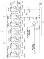
- the sensor apparatus which concerns on this embodiment is shown.
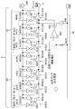
- An offset setting part and an offset switching part are shown.
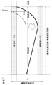
- a sensitivity setting part and a sensitivity switching part are shown.
- An example of the offset setting by an offset setting part is shown.
- An example of the sensitivity setting by a sensitivity setting part is shown.
- An example of sensitivity and offset switching by the switching unit is shown.
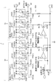
- the offset switching part which concerns on a modification is shown.
- An example of offset switching by the offset switching unit is shown.
- FIG. 1 shows a sensor device 1 according to this embodiment.
- the sensor device 1 detects the magnitude of the physical quantity and outputs an output signal.
- the sensor apparatus 1 detects the magnitude of the pressure as an example.
- the sensor device 1 switches the temperature characteristics when the temperature exceeds a threshold value (also referred to as a threshold temperature, which is 100 ° C. as an example).
- the sensor device 1 includes a sense circuit 2, an amplifier circuit 3, a temperature sensor 4, a storage unit 5, a sensitivity setting unit 6, an offset setting unit 7, and a switching unit 8.
- the sense circuit 2 outputs a sense signal corresponding to the magnitude of the detected physical quantity (in this embodiment, as an example, pressure).
- the sense circuit 2 includes a Wheatstone bridge 20 including four piezoresistors 21 to 24.
- the piezoresistors 21 to 24 may be disposed on a thin film diaphragm (not shown).
- the piezoresistors 21 to 24 may be disposed at equal intervals along the outer periphery of the circular diaphragm.
- the piezoresistors 21 to 24 may change their resistance values according to the deformation of the diaphragm and cause a potential difference in the output of the Wheatstone bridge 20.
- the sense circuit 2 may be adjustable in sensitivity in accordance with a supplied current (also referred to as a bridge current). In this embodiment, as an example, the sensitivity of the sense circuit 2 may increase as the bridge current increases.
- the sense circuit 2 may output a positive / negative sense signal indicating a potential difference corresponding to the detected pressure level to the amplifier circuit 3.
- the amplifier circuit 3 amplifies the sense signal.
- the amplifier circuit 3 may amplify the potential difference of the sense signal.
- the amplification factor by the amplifier circuit 3 may be a fixed value, for example, 300 times.
- the amplifier circuit 3 may have an offset voltage input terminal 30 for adjusting the offset, and may adjust the offset according to the input offset voltage. In this embodiment, as an example, the offset of the amplifier circuit 3 may increase as the offset voltage increases.
- the amplifier circuit 3 may output the amplified sense signal to the outside as an output signal.
- the temperature sensor 4 measures the temperature of the sense circuit 2 as a temperature measurement value.
- the temperature sensor 4 may supply the measurement result to the sensitivity setting unit 6, the offset setting unit 7, and the switching unit 8.
- the temperature sensor 4 may supply a current corresponding to the temperature measurement value.
- the storage unit 5 stores one or a plurality of setting parameters that determine the setting contents of the sensitivity setting unit 6 and / or the offset setting unit 7.
- the storage unit 5 may store at least one setting parameter for each of the sensitivity setting unit 6 and the offset setting unit 7.
- the storage unit 5 stores two setting parameters (m1) and (m2), which will be described later, in the sensitivity setting unit 6, and the two setting parameters (described later) in the offset setting unit 7.
- n1) and (n2) may be stored.
- the values of the setting parameters may be set in advance when the sensor device 1 is manufactured. Instead, the storage unit 5 may store a plurality of values for each setting parameter, and may be set by the user as to which value is used.
- the storage unit 5 may be an EPROM (Erasable Programmable Read Only Memory), but may be another storage device.
- the sensitivity setting unit 6 sets a reference current for the bridge current supplied to the sense circuit 2.
- the reference current is a current used as a reference.
- the reference current is supplied to the sense circuit 2 when a temperature measurement value is equal to or lower than a threshold temperature described later.
- the sensitivity setting unit 6 may include a reference sensitivity setting unit 60 and / or a temperature characteristic sensitivity setting unit 61 that sets a reference current.
- the sensitivity setting unit 6 includes both the reference sensitivity setting unit 60 and the temperature special sensitivity setting unit 61, the reference sensitivity setting unit 60 and the temperature special sensitivity setting unit 61 may cooperate to set the reference current.
- the reference sensitivity setting unit 60 sets a reference current according to a fixed setting parameter (m1).
- the setting parameter (m1) may be set so that an error between the pressure indicated by the output signal of the sensor device 1 and the actual pressure falls within an allowable range.
- the setting parameter (m1) may be set so that an error at a reference temperature (room temperature as an example) falls within an allowable range.
- the setting parameter (m1) may be supplied from the storage unit 5.
- the temperature characteristic sensitivity setting unit 61 sets a reference current according to a fixed setting parameter (m2), and continuously varies the reference current according to the temperature measurement value.
- the setting parameter (m2) may be set so that the temperature characteristics of the sensor device 1 are improved.
- the setting parameter (m2) may be set such that the error falls within an allowable range over a temperature range in which the sensor device 1 can be used.
- the setting parameter (m2) may be supplied from the storage unit 5.
- the offset setting unit 7 sets a reference voltage supplied to the offset voltage input terminal 30 of the amplifier circuit 3.
- the reference voltage is a voltage used as a reference.
- the reference voltage is supplied to the sense circuit 2 when a temperature measurement value is equal to or lower than a threshold temperature described later.
- the offset setting unit 7 may include a reference offset setting unit 70 and / or a temperature special offset setting unit 71 that sets a reference voltage.
- the offset setting unit 7 includes both the reference offset setting unit 70 and the temperature special offset setting unit 71, the reference offset setting unit 70 and the temperature special offset setting unit 71 may cooperate to set the reference voltage.
- the reference offset setting unit 70 sets a reference current according to a fixed setting parameter (n1).
- the setting parameter (n1) may be set so that an error between the pressure indicated by the output signal of the sensor device 1 and the actual pressure falls within an allowable range.
- the setting parameter (n1) may be set so that an error at a reference temperature (room temperature as an example) falls within an allowable range.
- the setting parameter (n1) may be supplied from the storage unit 5.
- the temperature special offset setting unit 71 sets the reference voltage according to the fixed setting parameter (n2), and continuously varies the reference voltage according to the temperature measurement value.
- the setting parameter (n2) may be set so that the temperature characteristics of the sensor device 1 are improved.
- the setting parameter (n2) may be set such that the error falls within an allowable range over a temperature range in which the sensor device 1 can be used.
- the setting parameter (m2) may be supplied from the storage unit 5.
- the switching unit 8 switches at least one of the sensitivity of the sense circuit 2 and the offset of the amplifier circuit 3 discontinuously depending on whether or not the temperature measurement value exceeds the threshold temperature. Switching to discontinuous may be switching so that sensitivity and offset change discontinuously with respect to temperature change.
- the threshold temperature may be set in advance when the sensor device 1 is manufactured, or may be set by the user.
- the threshold temperature may be stored in the storage unit 5.
- the switching unit 8 may include a sensitivity switching unit 80 and an offset switching unit 81.
- Sensitivity switching unit 80 switches the bridge current supplied to the sense circuit 2.
- the sensitivity switching unit 80 may change the bridge current from the reference current according to whether the temperature measurement value exceeds the threshold temperature.
- the offset switching unit 81 switches the voltage supplied to the offset voltage input terminal 30.
- the offset switching unit 81 may change the voltage supplied to the offset voltage input terminal 30 from the reference voltage depending on whether the temperature measurement value exceeds the threshold temperature.
- At least one of the sensitivity of the sense circuit 2 and the offset of the amplifier circuit 3 is switched discontinuously depending on whether the temperature measurement value exceeds the threshold temperature. Therefore, since the temperature characteristic of the sensor device 1 can be switched with the threshold temperature as a boundary, an output error due to the temperature characteristic can be reduced.
- the sensitivity switching unit 80 switches the bridge current of the sense circuit 2
- the sensitivity of the sense circuit 2 is switched according to whether or not the temperature measurement value exceeds the threshold temperature. Therefore, the temperature characteristic of the sensor device 1 can be switched reliably with the threshold temperature as a boundary.
- the offset switching unit 81 switches the offset voltage of the offset voltage input terminal 30, the offset of the amplifier circuit 3 is switched according to whether or not the temperature measurement value exceeds the threshold temperature. Therefore, the temperature characteristic of the sensor device 1 can be switched reliably with the threshold temperature as a boundary.
- the sensitivity setting unit 6 sets the reference current of the bridge current, the sensitivity can be set to cancel the characteristic variation. Further, since the temperature characteristic sensitivity setting unit 61 continuously changes the reference current according to the temperature measurement value, the temperature characteristic of the sensitivity can be switched by each of the temperature characteristic sensitivity setting unit 61 and the sensitivity switching unit 80. . Therefore, output errors due to temperature characteristics can be further reduced.
- the offset setting unit 7 sets the reference voltage of the offset voltage, the offset can be set to cancel the characteristic variation. Further, since the temperature special offset setting unit 71 continuously varies the reference voltage according to the temperature measurement value, the temperature characteristic of the offset can be switched by the temperature special offset setting unit 71 and the offset switching unit 81, respectively. . Therefore, output errors due to temperature characteristics can be further reduced.
- FIG. 2 shows the offset setting unit 7 and the offset switching unit 81.
- the reference offset setting unit 70 and the temperature special offset setting unit 71 of the offset setting unit 7 set a reference voltage of the offset voltage supplied to the offset voltage input terminal 30, and the offset switching unit 81 The offset voltage is changed from the reference voltage depending on whether the measured value exceeds the threshold temperature T1.
- the reference offset setting unit 70 includes a power source 700 and a plurality of current supply units 701 connected in parallel between the power source 700 and the offset voltage input terminal 30 (four current supply units 701 (0) to 701 (0) to 701 as an example in this embodiment). 701 (3)) and a resistor Rc connected between the offset voltage input terminal 30 and the reference potential (ground potential in this embodiment), and a voltage corresponding to the current supplied from the current supply unit 701 Generated by the resistor Rc and supplied to the offset voltage input terminal 30.
- the power supply 700 outputs a positive voltage so that the current supplied from the current supply unit 701 flows to the offset voltage input terminal 30 and thus to the ground side.
- the four current supply units 701 (0) to 701 (3) may output currents according to the value of the setting parameter (n1) supplied from the storage unit 5.
- the four current supply units 701 (0) to 701 (3) output a current n1 ⁇ Ic obtained by multiplying the setting parameter (n1) indicated by a value from 0 to 15 by the current Ic.
- the current Ic may be a constant current regardless of the temperature change.
- the IC may be a current that increases the offset voltage by 5 mV.
- Each of the current supply units 701 (0) to 701 (3) includes a current source 7010 (0) to 7010 (3) connected between the power source 700 and the offset voltage input terminal 30, and a current source 7010 (0) to Switches 7011 (0) to 7011 (3) for individually cutting off currents flowing from 7010 (3) may be provided.
- Current sources 7010 (0) to 7010 (3) output currents of 1 ⁇ Ic, 2 ⁇ Ic, 4 ⁇ Ic, and 8 ⁇ Ic.
- the switches 7011 (0) to 7011 (3) open and close according to the value of the setting parameter (n1).
- the switches 7011 (0) to 7011 (3) are respectively associated with the 0th bit to the 3rd bit of the setting parameter (n1) represented by a 4-digit binary number, and the value of the corresponding bit is 0. When it is, it is open, and when it is 1, it is closed.
- the switches 7011 (0) to 7011 (3) may be MOSFETs.
- a buffer circuit 7012 may be provided at the gates of the switches 7011 (0) to 7011 (3).
- the temperature-special offset setting unit 71 includes a plurality of current supply units 711 (three current supply units 711 (0) to 711 (2 as an example in the present embodiment) connected in parallel between the power source 700 and the offset voltage input terminal 30. )), And a voltage corresponding to the current supplied from the current supply unit 711 is generated by the resistor Rc and supplied to the offset voltage input terminal 30.
- the three current supply units 711 (0) to 711 (2) may output a current corresponding to the value of the setting parameter (n2) supplied from the storage unit 5.
- the three current supply units 711 (0) to 711 (2) output a current n2 ⁇ It obtained by multiplying the setting parameter (n2) indicated by a value from 0 to 7 by the current It.
- the current It may be a current that fluctuates with a change in temperature, and fluctuates linearly according to a change in temperature measurement value, for example.
- the temperature special offset setting unit 71 continuously varies the reference voltage according to the temperature measurement value.
- Each of the current supply units 711 (0) to 711 (2) includes a current source 7110 (0) to 7110 (2) connected between the power source 700 and the offset voltage input terminal 30, and a current source 7110 (0) to Switches 7111 (0) to 7111 (2) that individually block currents flowing from 7110 (2).
- the current sources 7110 (0) to 7110 (2) can change the output current linearly according to the temperature measurement value, and output currents of 1 ⁇ It, 2 ⁇ It, and 4 ⁇ It.
- the switches 7111 (0) to 7111 (2) open and close according to the value of the setting parameter (n2).
- the switches 7111 (0) to 7111 (2) are respectively associated with the 0th bit to the 2nd bit of the setting parameter (n2) represented by a 3-digit binary number, and the value of the corresponding bit is 0. When it is, it is open, and when it is 1, it is closed.
- the switches 7111 (0) to 7111 (2) may be MOSFETs.
- a buffer circuit 7112 may be provided at the gates of the switches 7111 (0) to 7111 (2).
- the offset switching unit 81 includes a variable resistor 810 connected between the offset voltage input terminal 30 and the ground, and a comparator 811 that compares the temperature measurement value and the threshold temperature T1.
- the variable resistor 810 includes a plurality of resistors R (two resistors Rc and R1 as an example in this embodiment) connected in parallel between the offset voltage input terminal 30 and the ground, and one of the resistors R (this embodiment). Then, a switch 8100 for cutting off a current flowing through the resistor R1) is provided.
- the resistance value of the variable resistor 810 is Rc when the switch 8100 is open, and (Rc / R1) / (Rc + R1) when the switch 8100 is closed.
- the resistance value (Rc / R1) / (Rc + R1) may be smaller than the resistance value Rc.
- the resistor R has a common configuration in the reference offset setting unit 70 and the offset switching unit 81, but may be provided individually for each.
- the switch 8100 may be opened / closed according to an output signal from the comparator 811. Thereby, the resistance value of the variable resistor 810 is switched according to the comparison result of the comparator 811.
- the switch 8100 may be a MO
- the comparator 811 may compare a voltage corresponding to the temperature measurement value with a voltage corresponding to the threshold temperature T1 (also referred to as a threshold voltage). For example, a voltage corresponding to the threshold temperature T1 may be input to the non-inverting input terminal of the comparator 811. A voltage corresponding to the output current of the temperature sensor 4 (for example, a voltage generated by a resistor 8110 connected between the inverting input terminal and the ground) may be input to the inverting input terminal of the comparator 811. Thereby, when the measured temperature value exceeds the threshold temperature T1, the switch 8100 is closed, and when the measured temperature value does not exceed the threshold temperature T1, the switch 8100 is opened. As a result, when the measured temperature value exceeds the threshold temperature T1, the resistance value of the variable resistor 810 becomes smaller than when the measured temperature value does not exceed the threshold temperature T1, and the offset voltage supplied to the offset voltage input terminal 30 becomes smaller. The offset becomes lower.
- the offset switching unit 81 when the temperature measurement value exceeds the threshold temperature T1, the resistance value of the variable resistor 810, and thus the offset voltage can be reduced to switch the temperature characteristic of the offset.
- FIG. 3 shows the sensitivity setting unit 6 and the sensitivity switching unit 80.
- the reference sensitivity setting unit 60 and the temperature characteristic sensitivity setting unit 61 of the sensitivity setting unit 6 set the reference current of the bridge current of the sense circuit 2, and the sensitivity switching unit 80 has a temperature measurement value of the threshold temperature.
- the bridge current is changed from the reference current according to whether or not T1 is exceeded.
- the reference sensitivity setting unit 60 includes a power supply 600 and a plurality of current supply units 601 connected in parallel between the power supply 600 and the sense circuit 2 (four current supply units 601 (0) to 601 (in this embodiment as an example). 3)), and supplies the current supplied from the current supply unit 601 to the sense circuit 2.
- the power supply 600 outputs a positive voltage so that the current supplied from the current supply unit 601 flows to the sense circuit 2 side.
- the four current supply units 601 (0) to 601 (3) may output currents according to the value of the setting parameter (m1) supplied from the storage unit 5.
- the four current supply units 601 (0) to 601 (3) output a current m1 ⁇ Ic obtained by multiplying the setting parameter (m1) indicated by a value from 0 to 15 by the current Ic.
- the current Ic in the reference sensitivity setting unit 60 may be the same as or different from the current Ic in the reference offset setting unit 70.
- Each of the current supply units 601 (0) to 601 (3) includes a current source 6010 (0) to 6010 (3) connected between the power supply 600 and the sense circuit 2, and a current source 6010 (0) to 6010 ( 3) switches 6011 (0) to 6011 (3) that individually cut off the currents flowing from 3).
- Current sources 6010 (0) to 6010 (3) output currents of 1 ⁇ Ic, 2 ⁇ Ic, 4 ⁇ Ic, and 8 ⁇ Ic.
- the switches 6011 (0) to 6011 (3) open and close according to the value of the setting parameter (m1).
- the switches 6011 (0) to 6011 (3) are respectively associated with the 0th bit to the 3rd bit of the setting parameter (m1) represented by a 4-digit binary number, and the value of the corresponding bit is 0. When it is, it is open, and when it is 1, it is closed.
- the switches 6011 (0) to 6011 (3) may be MOSFETs.
- a buffer circuit 6012 may be provided at the gates of the switches 6011 (0) to 6011 (3).
- the temperature characteristic sensitivity setting unit 61 includes a plurality of current supply units 611 (three current supply units 611 (0) to 611 (2) as an example in the present embodiment) connected in parallel between the power source 600 and the sense circuit 2. The current supplied from the current supply unit 611 is supplied to the sense circuit 2.
- the three current supply units 611 (0) to 611 (2) may output a current corresponding to the value of the setting parameter (m2) supplied from the storage unit 5.
- the three current supply units 611 (0) to 611 (2) output a current m2 ⁇ It obtained by multiplying the setting parameter (m2) indicated by a value from 0 to 7 by the current It.
- the temperature characteristic sensitivity setting unit 61 continuously varies the reference current according to the temperature measurement value.
- the current It in the temperature characteristic sensitivity setting unit 61 may be the same as or different from the current It in the temperature characteristic offset setting unit 71.
- Each of the current supply units 611 (0) to 611 (2) includes a current source 6110 (0) to 6110 (2) connected between the power supply 600 and the sense circuit 2, and a current source 6110 (0) to 6110 ( 2) switches 6111 (0) to 6111 (2) that individually cut off the currents flowing from 2).
- the current sources 6110 (0) to 6110 (2) can change the output current linearly according to the temperature measurement value, and output currents of 1 ⁇ It, 2 ⁇ It, and 4 ⁇ It.
- the switches 6111 (0) to 6111 (2) open and close according to the value of the setting parameter (m2).
- the switches 6111 (0) to 6111 (2) are respectively associated with the 0th bit to the 2nd bit of the setting parameter (m2) represented by a 3-digit binary number, and the value of the corresponding bit is 0. When it is, it is open, and when it is 1, it is closed.
- the switches 6111 (0) to 6111 (2) may be MOSFETs.
- a buffer circuit 6112 may be provided at the gates of the switches 6111 (0) to 6111 (2).
- the sensitivity switching unit 80 includes a current source 800 connected to the sense circuit 2, a switch 801 that cuts off a current flowing between the current source 800 and the sense circuit 2, and a comparator 802 that compares the measured temperature value and the threshold temperature T1.
- the current source 800 may be capable of linearly changing the output current according to the temperature measurement value, and may flow any current of 1 ⁇ It, 2 ⁇ It, 3 ⁇ It, 4 ⁇ It, for example.
- the current source 800 may be a sink type and may be connected between the sense circuit 2 and the ground.
- the switch 8000 may be provided between the sense circuit 2 and the current source 800 and may be opened / closed according to an output signal from the comparator 802. Thereby, the current source 800 is connected to the sense circuit 2 according to the comparison result of the comparator 802, and the bridge current is switched.
- the current source 800 is a sink type. Therefore, when the switch 8000 is closed, the bridge current may be reduced by the amount of current drawn into the current source 800 as compared to the open case.
- Switch 8000 may be a MOSFET.
- the comparator 802 may compare the voltage according to the temperature measurement value with the voltage according to the threshold temperature T1. For example, a threshold voltage corresponding to the threshold temperature T1 may be input to the non-inverting input terminal of the comparator 802. A voltage corresponding to the output current of the temperature sensor 4 (for example, a voltage generated by a resistor 8020 connected between the inverting input terminal and the ground) may be input to the inverting input terminal of the comparator 802. Thereby, when the temperature measurement value exceeds the threshold temperature T1, the switch 8000 is closed, and when the temperature measurement value does not exceed the threshold temperature T1, the switch 8000 is opened.
- the comparator 802 may have a configuration common to the sensitivity switching unit 80 and the offset switching unit 81.
- the bridge current of the sense circuit 2 can be reduced to switch the temperature characteristic of the sensitivity of the sense circuit 2.
- FIG. 4 shows an example of offset setting by the offset setting unit 7.
- the horizontal axis indicates the temperature
- the vertical axis indicates the error in the output signal due to the temperature characteristics.
- the operating temperature range is a temperature range in which the sensor device 1 can be used, and is a temperature range in which the measurement error should be within the upper and lower limits of the standard. As an example, the operating temperature range may be 5 to 150 ° C.
- the offset setting unit 7 sets the reference voltage of the offset voltage according to the fixed setting parameters (n1) and (n2) stored in the storage unit 5.
- the setting parameters (n1) and (n2) are not appropriately set, such as when the sensor device 1 is in the middle of manufacturing, the error of the output signal is as shown in the broken line graph as an example. Although it becomes approximately 0 in the normal temperature region, it becomes non-linearly large due to an increase in leakage current in the high temperature region and can exceed the upper limit of the specification at the temperature T11.
- the setting parameters (n1) and (n2) are appropriately set in order to adjust the offset, as shown in the solid line graph as an example, the error is shifted to the lower limit side of the standard. The error falls within the upper limit of the standard and the lower limit of the standard over the entire area. However, as indicated by shading in the figure, the margin for the upper and lower standard limits of the error is small.
- FIG. 5 shows an example of sensitivity setting by the sensitivity setting unit 6.
- the horizontal axis indicates the temperature
- the vertical axis indicates the error in the output signal due to the temperature characteristics.
- the sensitivity setting unit 6 sets the reference current of the bridge current according to the fixed setting parameters (m1) and (m2) stored in the storage unit 5.
- the setting parameters (m1) and (m2) are not appropriately set, such as when the sensor device 1 is in the middle of manufacturing, the error of the output signal is in the normal temperature range as shown in the broken line graph as an example. Although it becomes approximately 0, it becomes non-linearly large due to an increase in leakage current in the high temperature region, and can exceed the upper limit of the specification at temperature T21.
- the setting parameters (m1) and (m2) are appropriately set to adjust the sensitivity, as shown in the solid line graph as an example, the inclination of the temperature characteristic of the error changes, resulting in the operating temperature. The error falls between the upper and lower specification limits over the entire range. However, as indicated by shading in the figure, the margin for the upper and lower standard limits of the error is small.
- FIG. 6 shows an example of sensitivity and offset switching by the switching unit 8.
- the horizontal axis indicates the temperature
- the vertical axis indicates the error in the output signal due to the temperature characteristics.
- the switching unit 8 switches the sensitivity of the sense circuit 2 to be discontinuous by changing the bridge current from the reference current when the measured temperature value exceeds the threshold temperature T1, and the offset voltage is changed to the reference voltage.
- the offset of the amplifier circuit 3 is switched discontinuously.
- the temperature characteristic of the sensor device 1 is switched with the threshold temperature T1 as a boundary.
- the error value range over the entire operating temperature range is narrower than in FIGS. Becomes larger.
- FIG. 7 shows an offset switching unit 82 according to a modification.
- the switching unit 8 may include an offset switching unit 82 instead of the offset switching unit 81 in the above embodiment.
- the offset switching unit 82 includes a variable resistor 820 connected between the offset voltage input terminal 30 and the ground, a temperature measurement value, and a plurality of threshold temperatures (two threshold temperatures T1, T2 as an example in this modification). Comparators 821 and 822 for comparison are included.
- the threshold temperatures T1 and T2 may satisfy T1 ⁇ T2, the threshold temperature T1 may be 100 ° C., and the threshold temperature T2 may be 120 ° C.
- the variable resistor 820 includes a plurality of resistors R (three resistors Rc, R1, R2 as an example in the present modification) connected in parallel between the offset voltage input terminal 30 and the ground, and one of the resistors R (this In the modified example, switches 8200 and 8201 for cutting off the current flowing through the resistors R1 and R2) are provided.
- the resistance value of the variable resistor 820 is Rc when the switches 8200 and 8201 are open, and is (Rc ⁇ R1) / (Rc + R1) when the switch 8200 is closed, and the switches 8200 and 8201 are closed.
- the resistance value (Rc ⁇ R1 ⁇ R2) / (R1 ⁇ R2 + Rc ⁇ R2 + Rc ⁇ R1) may be smaller than the resistance value (Rc / R1) / (Rc + R1).
- the switch 8200 may be opened / closed according to an output signal from the comparator 821, and the switch 8201 may be opened / closed according to an output signal from the comparator 822. As a result, the resistance value of the variable resistor 820 is switched stepwise in accordance with the comparison result of the comparators 821 and 822.
- the switches 8200 and 8201 may be MOSFETs.
- Each of the comparators 821 and 822 may compare a voltage corresponding to the temperature measurement value and a voltage corresponding to the threshold temperature T1 or T2. As a result, when the temperature measurement value does not exceed either of the threshold temperatures T1 and T2, the switches 8200 and 8201 are opened, and when the temperature measurement value exceeds the threshold temperature T1, the switch 8200 is closed and the temperature measurement value is When the threshold temperature T2 is exceeded, the switches 8200 and 8201 are closed. As a result, the voltage supplied to the offset voltage input terminal 30 decreases stepwise and the offset is switched stepwise depending on which of the two threshold temperatures T1 and T2 the temperature measurement value exceeds.
- the offset switching unit 82 that switches the offset stepwise is described as being provided in the switching unit 8, but in addition to / in place, the sensitivity switching unit 80 that switches the sensitivity stepwise is switched.
- the unit 8 may be provided. Similar to the offset switching unit 82, the sensitivity switching unit 80 may switch the sensitivity stepwise in accordance with which of the plurality of threshold temperatures the temperature measurement value exceeds.
- FIG. 8 shows an example of offset switching by the offset switching unit 82.
- the horizontal axis indicates the temperature
- the vertical axis indicates the error in the output signal due to the temperature characteristics.
- the offset switching unit 8 discontinuously offsets the offset of the amplifier circuit 3 by changing the offset voltage stepwise from the reference voltage when the measured temperature value exceeds the threshold temperatures T1 and T2. Switch automatically.
- the temperature characteristics of the sensor device 1 are switched with the threshold temperatures T1 and T2 as a boundary.
- the error range over the entire operating temperature range is further narrowed compared to FIG. Becomes even bigger.
- the sensitivity switching unit 80 and the offset switching unit 81 have been described as using the same threshold temperature T1, separate threshold temperatures may be used.
- the sensitivity switching unit 80 has been described as having the sink type current source 800 connected between the sense circuit 2 and the ground, but the source type current source connected between the power source 600 and the sense circuit 2 is used. You may have.
- the switch 801 of the sensitivity switching unit 80 may be closed when the temperature measurement value does not exceed the threshold temperature, and may be open when the temperature exceeds the threshold temperature. Accordingly, as in the above-described embodiment, when the temperature measurement value exceeds the threshold temperature, the bridge current is smaller than when the temperature measurement value does not exceed the threshold temperature, and the sensitivity of the sense circuit 2 is reduced.
- the sensor device 1 has been described as including the temperature sensor 4, the storage unit 5, the sensitivity setting unit 6, and the offset setting unit 7, any of these may be omitted.
- the temperature of the sense circuit 2 may be acquired from an external temperature sensor.
- the opening / closing of the switches of the sensitivity setting unit 6 and / or the offset setting unit 7 may be set by default.
- the switching unit 8 has been described as switching the sensitivity and / or offset when the temperature measurement value exceeds the threshold temperature, but may be switched when the temperature falls below the threshold temperature (for example, 0 ° C.).
- the sense circuit 2 has been described as detecting the magnitude of pressure as a physical quantity, other physical quantities such as acceleration may be detected.
Landscapes
- Physics & Mathematics (AREA)
- General Physics & Mathematics (AREA)
- Amplifiers (AREA)
- Indication And Recording Devices For Special Purposes And Tariff Metering Devices (AREA)
- Measuring Fluid Pressure (AREA)
Abstract
Il existe une demande pour une réduction supplémentaire des erreurs de sortie provenant de caractéristiques de température. L'invention concerne un dispositif de capteur comprenant un circuit de détection pour délivrer en sortie un signal de détection qui correspond à l'amplitude d'une quantité physique détectée, un circuit d'amplification pour amplifier le signal de détection, et une unité de commutation pour commuter de manière discontinue la sensibilité du circuit de détection et/ou le décalage du circuit d'amplification selon qu'une valeur de mesure de température dépasse ou non une valeur seuil.
Priority Applications (3)
| Application Number | Priority Date | Filing Date | Title |
|---|---|---|---|
| JP2020505645A JP6856170B2 (ja) | 2018-03-14 | 2019-01-28 | センサ装置 |
| CN201980004057.XA CN111094925B (zh) | 2018-03-14 | 2019-01-28 | 传感器装置 |
| US16/794,231 US11422049B2 (en) | 2018-03-14 | 2020-02-19 | Sensor device configured to reduce output errors due to temperature characteristics |
Applications Claiming Priority (2)
| Application Number | Priority Date | Filing Date | Title |
|---|---|---|---|
| JP2018-046995 | 2018-03-14 | ||
| JP2018046995 | 2018-03-14 |
Related Child Applications (1)
| Application Number | Title | Priority Date | Filing Date |
|---|---|---|---|
| US16/794,231 Continuation US11422049B2 (en) | 2018-03-14 | 2020-02-19 | Sensor device configured to reduce output errors due to temperature characteristics |
Publications (1)
| Publication Number | Publication Date |
|---|---|
| WO2019176332A1 true WO2019176332A1 (fr) | 2019-09-19 |
Family
ID=67906606
Family Applications (1)
| Application Number | Title | Priority Date | Filing Date |
|---|---|---|---|
| PCT/JP2019/002673 Ceased WO2019176332A1 (fr) | 2018-03-14 | 2019-01-28 | Dispositif de capteur |
Country Status (4)
| Country | Link |
|---|---|
| US (1) | US11422049B2 (fr) |
| JP (1) | JP6856170B2 (fr) |
| CN (1) | CN111094925B (fr) |
| WO (1) | WO2019176332A1 (fr) |
Families Citing this family (4)
| Publication number | Priority date | Publication date | Assignee | Title |
|---|---|---|---|---|
| US11735902B2 (en) | 2020-03-24 | 2023-08-22 | Analog Devices International Unlimited Company | Bipolar junction transistor heater circuit |
| WO2022056850A1 (fr) * | 2020-09-18 | 2022-03-24 | 深圳纽迪瑞科技开发有限公司 | Capteur de température et de pression et dispositif électronique |
| US12451880B2 (en) * | 2021-02-25 | 2025-10-21 | Panasonic Intellectual Property Management Co., Ltd. | On-state voltage measurement circuit |
| JP7550699B2 (ja) * | 2021-03-31 | 2024-09-13 | 本田技研工業株式会社 | 触覚センサ、感度切替回路、および感度切替方法 |
Citations (5)
| Publication number | Priority date | Publication date | Assignee | Title |
|---|---|---|---|---|
| US5197334A (en) * | 1991-06-04 | 1993-03-30 | Schlumberger Industries, Inc. | Programmable compensation of bridge circuit thermal response |
| JPH05256716A (ja) * | 1992-03-13 | 1993-10-05 | Mitsubishi Electric Corp | 半導体装置 |
| JPH08145715A (ja) * | 1994-11-25 | 1996-06-07 | Matsushita Electric Works Ltd | センサの温度補正回路 |
| JP2000214030A (ja) * | 1999-01-26 | 2000-08-04 | Matsushita Electric Works Ltd | 圧力センサ回路 |
| JP2012002742A (ja) * | 2010-06-18 | 2012-01-05 | Yamatake Corp | 物理量センサ |
Family Cites Families (19)
| Publication number | Priority date | Publication date | Assignee | Title |
|---|---|---|---|---|
| GB1591620A (en) * | 1976-12-21 | 1981-06-24 | Nat Res Dev | Signal-conditioning circuits |
| DE3503489A1 (de) * | 1985-01-30 | 1986-07-31 | Siemens AG, 1000 Berlin und 8000 München | Schaltungsanordnung zur kompensation der temperaturabhaengigkeit von empfindlichkeit und nullpunkt eines piezoresistiven drucksensors |
| GB8705192D0 (en) * | 1987-03-05 | 1987-04-08 | Secr Defence | Transducer signal conditioner |
| US5343755A (en) * | 1993-05-05 | 1994-09-06 | Rosemount Inc. | Strain gage sensor with integral temperature signal |
| JP3419274B2 (ja) * | 1997-10-03 | 2003-06-23 | 富士電機株式会社 | センサ出力補償回路 |
| JP2002148131A (ja) * | 2000-11-10 | 2002-05-22 | Denso Corp | 物理量検出装置 |
| JP2003042870A (ja) | 2001-08-02 | 2003-02-13 | Denso Corp | センサ用温度特性補正回路装置及びセンサの温度特性補正方法 |
| JP4059056B2 (ja) * | 2002-10-18 | 2008-03-12 | 株式会社デンソー | センサ装置およびセンサ装置の出力特性切換方法 |
| US6870236B2 (en) * | 2003-05-20 | 2005-03-22 | Honeywell International, Inc. | Integrated resistor network for multi-functional use in constant current or constant voltage operation of a pressure sensor |
| US7073389B2 (en) * | 2003-10-02 | 2006-07-11 | Kulite Semiconductor Products, Inc. | Shunt calibration for electronic pressure switches |
| JP4107235B2 (ja) * | 2003-12-25 | 2008-06-25 | 株式会社デンソー | 力学量センサ構造 |
| JP4244895B2 (ja) | 2004-09-14 | 2009-03-25 | 株式会社デンソー | 物理量センサおよびその製造方法 |
| JP2007278725A (ja) * | 2006-04-03 | 2007-10-25 | Denso Corp | 物理量センサ |
| CN201491346U (zh) * | 2009-09-01 | 2010-05-26 | 福建科维光电科技有限公司 | Led灯温度补偿电路 |
| US9147443B2 (en) * | 2011-05-20 | 2015-09-29 | The Regents Of The University Of Michigan | Low power reference current generator with tunable temperature sensitivity |
| DE112012005548B4 (de) | 2011-12-28 | 2024-03-21 | Fuji Electric Co., Ltd. | Ausgangswertkorrekturverfahren für eine Sensorvorrichtung für eine physikalische Grösse, Ausgangskorrekturverfahren für einen Sensor für eine physikalische Grösse, Sensorvorrichtung für eine physikalische Grösse und Ausgangswertkorrekturvorrichtung für einen Sensor für eine physikalische Grösse |
| JP5900536B2 (ja) | 2013-09-30 | 2016-04-06 | 株式会社デンソー | センサ信号検出装置 |
| CN105306056B (zh) * | 2014-07-28 | 2019-04-23 | 北京自动化控制设备研究所 | 一种电流频率转换电路的标度因数温度补偿方法 |
| US9593994B2 (en) * | 2014-10-16 | 2017-03-14 | DunAn Sensing, LLC | Compensated pressure sensors |
-
2019
- 2019-01-28 WO PCT/JP2019/002673 patent/WO2019176332A1/fr not_active Ceased
- 2019-01-28 JP JP2020505645A patent/JP6856170B2/ja not_active Expired - Fee Related
- 2019-01-28 CN CN201980004057.XA patent/CN111094925B/zh not_active Expired - Fee Related
-
2020
- 2020-02-19 US US16/794,231 patent/US11422049B2/en active Active
Patent Citations (5)
| Publication number | Priority date | Publication date | Assignee | Title |
|---|---|---|---|---|
| US5197334A (en) * | 1991-06-04 | 1993-03-30 | Schlumberger Industries, Inc. | Programmable compensation of bridge circuit thermal response |
| JPH05256716A (ja) * | 1992-03-13 | 1993-10-05 | Mitsubishi Electric Corp | 半導体装置 |
| JPH08145715A (ja) * | 1994-11-25 | 1996-06-07 | Matsushita Electric Works Ltd | センサの温度補正回路 |
| JP2000214030A (ja) * | 1999-01-26 | 2000-08-04 | Matsushita Electric Works Ltd | 圧力センサ回路 |
| JP2012002742A (ja) * | 2010-06-18 | 2012-01-05 | Yamatake Corp | 物理量センサ |
Also Published As
| Publication number | Publication date |
|---|---|
| US11422049B2 (en) | 2022-08-23 |
| CN111094925A (zh) | 2020-05-01 |
| JP6856170B2 (ja) | 2021-04-07 |
| JPWO2019176332A1 (ja) | 2020-10-01 |
| CN111094925B (zh) | 2023-02-17 |
| US20200182725A1 (en) | 2020-06-11 |
Similar Documents
| Publication | Publication Date | Title |
|---|---|---|
| US11422049B2 (en) | Sensor device configured to reduce output errors due to temperature characteristics | |
| US20110247390A1 (en) | Method and mass flow controller for enhanced operating range | |
| US10247625B2 (en) | Apparatus for correcting of temperature measurement signal | |
| EP2302344A2 (fr) | Appareil de mesure de la température et son procédé | |
| JP4736508B2 (ja) | 物理量検出方法及びセンサ装置 | |
| US12334915B2 (en) | High side current detection circuit, overcurrent protection circuit, calibration method and electronic devices | |
| AU2014202006B2 (en) | Flow sensor with improved linear output | |
| US20200326244A1 (en) | Temperature sensor evaluation method | |
| TWI567406B (zh) | Magnetic sensor | |
| US8618839B2 (en) | Utilizing a sense amplifier to select a suitable circuit | |
| US20160349132A1 (en) | Physical quantity detector | |
| CN105466460B (zh) | 生物传感器的电路温度漂移补偿系统及方法 | |
| JP6341119B2 (ja) | センサ駆動装置 | |
| JPH11118617A (ja) | 温度調節器 | |
| CN109269655B (zh) | 温度感测电路及其校正方法 | |
| KR101971245B1 (ko) | Led 모듈 검사용 전류 제어 장치 | |
| KR101683460B1 (ko) | 미세온도 판단을 위한 이중화 온도 감지회로 | |
| TWI813369B (zh) | 電路裝置 | |
| US7345536B2 (en) | Amplifier circuit and control method thereof | |
| US10591332B2 (en) | Airflow meter | |
| JP2004045295A (ja) | センサ回路 | |
| JP2021167741A (ja) | 信号処理回路および荷重検出装置 | |
| KR101889780B1 (ko) | 미세온도 판단을 위한 이중화 온도 감지회로 | |
| JP3888196B2 (ja) | センサの出力特性調整方法 | |
| GB2606834A (en) | Sensor apparatus |
Legal Events
| Date | Code | Title | Description |
|---|---|---|---|
| 121 | Ep: the epo has been informed by wipo that ep was designated in this application |
Ref document number: 19767974 Country of ref document: EP Kind code of ref document: A1 |
|
| ENP | Entry into the national phase |
Ref document number: 2020505645 Country of ref document: JP Kind code of ref document: A |
|
| NENP | Non-entry into the national phase |
Ref country code: DE |
|
| 122 | Ep: pct application non-entry in european phase |
Ref document number: 19767974 Country of ref document: EP Kind code of ref document: A1 |