WO2019181355A1 - 物品移載装置 - Google Patents
物品移載装置 Download PDFInfo
- Publication number
- WO2019181355A1 WO2019181355A1 PCT/JP2019/006633 JP2019006633W WO2019181355A1 WO 2019181355 A1 WO2019181355 A1 WO 2019181355A1 JP 2019006633 W JP2019006633 W JP 2019006633W WO 2019181355 A1 WO2019181355 A1 WO 2019181355A1
- Authority
- WO
- WIPO (PCT)
- Prior art keywords
- gripping
- article
- unit
- robot hand
- food
- Prior art date
- Legal status (The legal status is an assumption and is not a legal conclusion. Google has not performed a legal analysis and makes no representation as to the accuracy of the status listed.)
- Ceased
Links
Images
Classifications
-
- B—PERFORMING OPERATIONS; TRANSPORTING
- B25—HAND TOOLS; PORTABLE POWER-DRIVEN TOOLS; MANIPULATORS
- B25J—MANIPULATORS; CHAMBERS PROVIDED WITH MANIPULATION DEVICES
- B25J13/00—Controls for manipulators
- B25J13/02—Hand grip control means
-
- B—PERFORMING OPERATIONS; TRANSPORTING
- B25—HAND TOOLS; PORTABLE POWER-DRIVEN TOOLS; MANIPULATORS
- B25J—MANIPULATORS; CHAMBERS PROVIDED WITH MANIPULATION DEVICES
- B25J9/00—Program-controlled manipulators
- B25J9/16—Program controls
- B25J9/1612—Program controls characterised by the hand, wrist, grip control
-
- B—PERFORMING OPERATIONS; TRANSPORTING
- B25—HAND TOOLS; PORTABLE POWER-DRIVEN TOOLS; MANIPULATORS
- B25J—MANIPULATORS; CHAMBERS PROVIDED WITH MANIPULATION DEVICES
- B25J11/00—Manipulators not otherwise provided for
- B25J11/0045—Manipulators used in the food industry
-
- B—PERFORMING OPERATIONS; TRANSPORTING
- B25—HAND TOOLS; PORTABLE POWER-DRIVEN TOOLS; MANIPULATORS
- B25J—MANIPULATORS; CHAMBERS PROVIDED WITH MANIPULATION DEVICES
- B25J15/00—Gripping heads and other end effectors
- B25J15/08—Gripping heads and other end effectors having finger members
- B25J15/10—Gripping heads and other end effectors having finger members with three or more finger members
-
- B—PERFORMING OPERATIONS; TRANSPORTING
- B65—CONVEYING; PACKING; STORING; HANDLING THIN OR FILAMENTARY MATERIAL
- B65G—TRANSPORT OR STORAGE DEVICES, e.g. CONVEYORS FOR LOADING OR TIPPING, SHOP CONVEYOR SYSTEMS OR PNEUMATIC TUBE CONVEYORS
- B65G47/00—Article or material-handling devices associated with conveyors; Methods employing such devices
- B65G47/74—Feeding, transfer, or discharging devices of particular kinds or types
- B65G47/90—Devices for picking-up and depositing articles or materials
- B65G47/905—Control arrangements
-
- B—PERFORMING OPERATIONS; TRANSPORTING
- B25—HAND TOOLS; PORTABLE POWER-DRIVEN TOOLS; MANIPULATORS
- B25J—MANIPULATORS; CHAMBERS PROVIDED WITH MANIPULATION DEVICES
- B25J9/00—Program-controlled manipulators
- B25J9/16—Program controls
- B25J9/1679—Program controls characterised by the tasks executed
-
- G—PHYSICS
- G05—CONTROLLING; REGULATING
- G05B—CONTROL OR REGULATING SYSTEMS IN GENERAL; FUNCTIONAL ELEMENTS OF SUCH SYSTEMS; MONITORING OR TESTING ARRANGEMENTS FOR SUCH SYSTEMS OR ELEMENTS
- G05B2219/00—Program-control systems
- G05B2219/30—Nc systems
- G05B2219/39—Robotics, robotics to robotics hand
- G05B2219/39514—Stability of grasped objects
-
- G—PHYSICS
- G05—CONTROLLING; REGULATING
- G05B—CONTROL OR REGULATING SYSTEMS IN GENERAL; FUNCTIONAL ELEMENTS OF SUCH SYSTEMS; MONITORING OR TESTING ARRANGEMENTS FOR SUCH SYSTEMS OR ELEMENTS
- G05B2219/00—Program-control systems
- G05B2219/30—Nc systems
- G05B2219/45—Nc applications
- G05B2219/45111—Meal, food assistance
Definitions
- This disclosure relates to an article transfer device.
- an object of the present disclosure is to provide an article transfer device that can stably hold an article.
- An article transfer device includes a gripping unit that grips an article, a robot hand that transfers an article gripped by the gripping part to a transfer destination, and a gripping unit in an article region where a plurality of articles are arranged
- a control unit for controlling the operation of the robot hand so as to grip a predetermined amount of articles and to transfer the gripped articles to the transfer destination.
- the gripping part is once closed and then opened and closed once or more times, the gripping part is closed and a predetermined amount of articles are gripped. Control the movement of the robot hand.
- This article transfer device performs the opening / closing operation of the gripping part one or more times in a state where the gripping part is inserted into the article region where a plurality of articles are arranged, and then closes the gripping part to grip the article. That is, the article transfer device once gathers a predetermined amount of articles to be grasped by opening and closing operations of the grasping unit, and then grasps the gathered articles. Thus, since the articles in a gathered state are held by the holding unit, the article transfer device can stably hold the articles by the holding unit.
- the control unit in the position of the gripping part when the gripping part is inserted into the article region, after closing the gripping part, opening the gripping part, and then closing the gripping part again, You may control operation
- the article transfer device gathers or holds the articles to be gripped by contacting a predetermined amount of articles to be gripped from a direction different from the previous time when the gripping unit is closed. it can. In this way, since the articles are gathered or gripped by the gripping portions from different directions, the article transfer device can gather the articles further and grip them more stably.
- the control unit includes a gripping unit around an axis along the insertion direction of the gripping unit when the gripping unit is closed at the position of the gripping unit when the gripping unit is inserted into the article region.
- the robot hand may be controlled so as to rotate at a predetermined second angle.
- the article transfer device rotates the gripping part in a state where a part of the plurality of articles is gripped, so that the article gripped by the gripping part and the surrounding articles (excluding gripping objects). Article).
- the article transfer device can stably hold a predetermined amount of articles to be gripped.
- the control unit holds the grip when the gripping part is inserted into the article area when the gripping part is opened after the gripping part is once closed after the gripping part is inserted into the article area.
- the operation of the robot hand may be controlled to be smaller than the opening amount of the part. In this case, the article transfer device can shorten the time for opening the gripping portion, and can quickly grip the article.
- the control unit inserts the gripping part into the article region, performs an opening / closing operation of opening the gripping part after closing the gripping part once, and then closing the gripping part to set a predetermined amount.
- the article transfer device can sequentially transfer a predetermined amount of articles from a plurality of articles in the article area to the transfer destination.
- the article can be stably gripped.
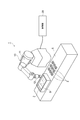
- FIG. 1 is a diagram illustrating a schematic configuration of an article transfer device according to an embodiment.
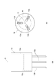
- Fig.2 (a) is a side view of a holding part.
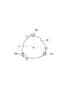
- FIG. 2B is a view of the grip portion as viewed from below.
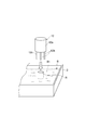
- FIG. 3 is a diagram illustrating a state in which the grip portion is inserted into the food group.
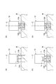
- Fig.4 (a) is a figure which shows a mode that the holding member was inserted in the foodstuff group.
- FIG. 4B is a diagram illustrating a state where the gripping member is once closed in the preliminary operation.
- FIG. 4C is a diagram illustrating a state in which the gripping member is opened in the preliminary operation.
- FIG. 4D is a diagram illustrating a state where the gripping member is closed in the gripping operation.
- FIG. 5 is a diagram illustrating a state in which the position where the food is gripped is changed by rotating the gripping portion.
- a food group B that is an aggregate of a plurality of food materials (articles) B ⁇ b> 1 (see FIG. 3) is contained (arranged) in the tray 2.
- the article transfer device 1 takes out a predetermined amount of food B1 from the tray 2 and transfers it to a container 3 such as a lunch box case.
- the article transfer device 1 includes a robot hand 10 and a control unit 20.
- the robot hand 10 is provided in the vicinity of the tray 2 and the container 3 placed on the work table 5.
- a plurality of containers 3 are arranged on the work table 5.
- the tray 2 and the container 3 are box bodies each having an upper opening.
- the robot hand 10 takes out the target gripping amount (predetermined amount) of the food B1 from the tray 2 and sequentially transfers it to the plurality of containers 3.
- the robot hand 10 includes an arm part 11 and a grip part 12.
- the grip portion 12 is attached to the tip portion of the arm portion 11.
- the arm part 11 has a plurality of joints.
- the arm part 11 can move the grip part 12 to a desired position by turning and bending the joint.
- the operation of the arm unit 11 is controlled by the control unit 20.
- the arm unit 11 operates based on a control signal output from the control unit 20.
- the gripping part 12 grips a part of the food B1 from the food group B.
- the gripping portion 12 includes a main body portion 12a, three gripping members 12b, and a drive portion 12c, as shown in FIGS. 2 (a) and 2 (b).
- the main body 12a is a housing having a central axis C.
- the main body 12a has, for example, a cylindrical outer shape.
- the main body 12a is made of metal, for example.
- the main body portion 12 a is attached to the distal end portion of the arm portion 11.
- the gripping member 12b is a rod-shaped member.
- the holding member 12b is made of, for example, resin, metal, or the like.
- the gripping member 12b is attached to the main body 12a so as to protrude downward from the main body 12a.
- the three gripping members 12b are respectively arranged on virtual circles centered on the central axis C.
- the three gripping members 12b are arranged at equal intervals (120 ° intervals) in the circumferential direction of the virtual circle.
- the gripping member 12b is movably provided on the main body 12a. Specifically, the grip member 12b moves by being driven by the drive unit 12c.
- the drive unit 12c moves the grip member 12b in a direction approaching the center axis C and a direction away from the center axis C.
- the drive unit 12c moves the three gripping members 12b in synchronization. As a result, the three gripping members 12b move in directions toward and away from each other.
- the drive unit 12c includes, for example, a motor and a link mechanism.
- the operation of the drive unit 12 c is controlled by the control unit 20.
- the drive unit 12 c operates based on a control signal output from the control unit 20.
- the gripping member 12 b of the gripping part 12 is inserted into the food group B by the arm part 11 moving the gripping part 12 from above to below along the vertical direction. That is, the insertion direction of the grip portion 12 into the food material group B coincides with the vertical direction.
- the inclination of the arm part 11 is adjusted so that the extending direction of the central axis C coincides with the vertical direction.
- the driving unit 12c moves the three gripping members 12b in a direction approaching each other, the gripping unit 12 is located inside the inscribed circle R (see FIG. 2B) inscribed in the three gripping members 12b. The foodstuff B1 located in is held.
- the gripping amount of the food B1 gripped by the gripping part 12 (the mass of the gripped food B1) is the insertion depth of the gripping member 12b inserted into the food group B and 3 when the gripping member 12b is plugged into the food group B. It is determined by the opening amount of the two gripping members 12b.
- the grip portion 12 can grip a larger amount of the food B1 as the insertion depth of the grip member 12b into the food group B is deeper.
- the gripping part 12 can grip a larger amount of the food B1 as the opening amount of the three gripping members 12b is larger.
- the robot hand 10 inserts the grip member 12b of the grip portion 12 into the food group B in the tray 2, and grips a part of the food material B1 from the food group B. Subsequently, the robot hand 10 moves the grip portion 12 to above the transfer destination container 3 by operating the arm portion 11. The robot hand 10 can transfer the gripped food B1 to the transfer destination container 3 by releasing the food B1 from the grip portion 12.
- the control unit 20 controls the operation of the robot hand 10.
- the control unit 20 may be housed in the robot hand 10 or provided outside the robot hand 10.
- the control unit 20 is an electronic control unit having a CPU (Central Processing Unit), a ROM (Read Only Memory), a RAM (Random Access Memory), and the like.
- the control unit 20 controls the operation of the robot hand 10 by outputting a control signal to the robot hand 10.
- control unit 20 inserts the gripping member 12b into the food group B (the article region on which the food B1 is placed) in the tray 2, grips a predetermined amount of the food B1, and holds the gripped food
- the operation of the robot hand 10 is controlled so that B1 is transferred to the transfer destination container 3.
- the control unit 20 determines the insertion depth and the opening amount when the gripping member 12b is inserted into the food group B so that a predetermined amount of the food B1 is gripped by the gripping part 12. Control.
- the controller 20 opens and closes the gripping member 12b after temporarily closing the three gripping members 12b at the position of the gripping portion 12 (main body portion 12a) when the gripping member 12b is inserted into the food group B. Is executed once or more. Then, after the opening / closing operation of the gripping member 12b, the control unit 20 controls the operation of the robot hand 10 so as to close the gripping member 12b and grip a predetermined amount of food B1.
- control unit 20 determines the insertion depth and the opening amount when the gripping member 12b is inserted into the food group B so that a predetermined amount of the food B1 can be gripped.
- the control unit 20 controls the operation of the gripping unit 12 so that the determined opening amount of the gripping member 12b is obtained.
- the control unit 20 controls the operation of the robot hand 10 so that the gripping member 12 b is inserted into the food group B to the determined insertion depth.
- the control unit 20 controls the operation of the gripping unit 12 so as to temporarily close the three gripping members 12b, as shown in FIG. As a result, a predetermined amount of food B1 positioned inside the three gripping members 12b is separated from the surrounding food B1 and collected. And the control part 20 controls operation
- the control unit 20 opens the gripping member 12b after the gripping member 12b is once closed after the gripping member 12b is inserted into the food group B, and the opening amount when the gripping member 12b is inserted into the food group B.
- the operation of the grip portion 12 is controlled so as to be smaller than the opening amount of the grip member 12b. That is, when the gripping member 12b is inserted into the food group B as shown in FIG. 4 (a), the control unit 20 opens the gripping member 12b when the gripping member 12b is opened again as shown in FIG.
- the operation of the grip portion 12 is controlled so as to be smaller than the opening amount of the grip member 12b.
- the length L (opening amount) from the central axis C to the gripping member 12b is shorter than the length L shown in FIG.
- the control unit 20 once closed the three gripping members 12b as shown in FIGS. 4 (b) and 4 (c) at the position of the gripping portion 12 when the gripping member 12b is inserted into the food group B.
- the holding part 12 is caused to perform an opening / closing operation to open the holding member 12b later one or more times.
- the opening / closing operation of opening the gripping member 12b after temporarily closing the gripping member 12b as shown in FIGS. 4B and 4C is referred to as “preliminary operation”.
- the control unit 20 causes the gripping unit 12 to perform the preliminary operation shown in FIGS. 4B and 4C once or more. That is, the grip part 12 gathers the foodstuff B1 by preliminary operation.
- the control unit 20 controls the gripping unit 12 to close the gripping member 12b and grip the food B1, as shown in FIG. 4 (d). Thereafter, the control unit 20 controls the operation of the robot hand 10 so that the gripped food B1 is transferred to the transfer destination container 3.
- FIG. 4D an operation of closing the gripping member 12b and gripping the food B1 in order to transfer the food B1 to the transfer destination is referred to as a “gripping operation”.
- the control unit 20 once closes the gripping member 12b, opens the gripping member 12b, and then closes the gripping member 12b again.
- the operation of the robot hand 10 is controlled so that the grip portion 12 rotates around a central axis C (around the axis along the insertion direction of the grip portion 12) by a predetermined first angle. That is, as illustrated in FIG. 5, the control unit 20 rotates the grip unit 12 by the first angle to change the position at which the grip member 12 b grips the food B 1 when the grip member 12 b is closed.
- the control unit 20 rotates the grip unit 12 by the first angle each time the grip member 12b is closed during the preliminary operation. It may be rotated one by one. Further, the control unit 20 may rotate the grip unit 12 by a first angle after the grip member 12b is closed in the preliminary operation and before the grip member 12b is closed in the grip operation.
- control unit 20 determines the gripping portion 12 around the central axis C when the gripping member 12b is closed at the position of the gripping portion 12 when the gripping member 12b is inserted into the food group B.
- the operation of the robot hand 10 is controlled to rotate by the second angle. That is, the control unit 20 rotates the entire gripping unit 12 by the second angle with the gripping member 12b closed.
- control unit 20 may rotate the grip unit 12 by a second angle when the grip member 12b is closed in the preliminary operation. Further, as shown in FIG. 4D, the control unit 20 may rotate the gripping part 12 by a second angle when the gripping member 12b is closed in the gripping operation.
- the second angle may be the same angle as the first angle described above, or may be a different angle.
- the control unit 20 controls the operation of the robot hand 10 so as to repeatedly execute the series of operations described with reference to FIGS. 4A to 4D, and sequentially transfers the food B1 to the plurality of containers 3. To do. That is, the control unit 20 inserts the gripping member 12b into the food group B, performs the opening / closing operation (preliminary operation) that opens the gripping member 12b after closing the gripping member 12b once, and then closes the gripping member 12b. The operation of the robot hand 10 is controlled so that a series of operations for gripping a predetermined amount of the food B1 is continuously performed a plurality of times.
- the article transfer device 1 performs the opening / closing operation (preliminary operation) of the gripping member 12b at least once in a state where the gripping member 12b is inserted into the food group B, and then closes the gripping member 12b.
- the food material B1 is gripped. That is, the article transfer apparatus 1 once gathers together a predetermined amount of food B1 to be grasped by opening and closing operations of the gripping member 12b, and then grips the gathered food B1.
- the article transfer device 1 can stably hold the food B1 by the holding unit 12.
- the article transfer device 1 rotates the gripping portion 12 around the central axis C by the first angle until the gripping member 12b is closed and then the gripping member 12b is opened and then the gripping member 12b is closed again.
- the article transfer device 1 gathers or holds the food B1 by bringing the gripping member 12b into contact with a predetermined amount of the food B1 to be gripped from a different direction from the previous closing time. it can.
- the article transfer apparatus 1 can gather the food B1 further and grip it more stably.
- the article transfer device 1 rotates the grip portion 12 around the central axis C by a second angle with the grip member 12b closed. As described above, the article transfer device 1 rotates the gripping portion 12 in a state where a part of the food B1 of the food group B is gripped, and thereby the food B1 gripped by the gripping member 12b and the surrounding food B1. (Food B1 that is not to be grasped) can be separated. As a result, the article transfer device 1 can stably hold a predetermined amount of the food B1 to be held.
- the controller 20 holds the grip when the gripping member 12b is inserted into the food group B when the gripping member 12b is opened after the gripping member 12b is once closed after the gripping member 12b is closed.
- the operation of the grip portion 12 is controlled so as to be smaller than the opening amount of the member 12b. In this case, the article transfer device 1 can shorten the time for opening the gripping member 12b, and can quickly grip the food B1.
- the article transfer device 1 inserts the gripping member 12b into the food group B, performs the preliminary operation of the gripping member 12b at least once, and then closes the gripping member 12b to grip and transfer a predetermined amount of the food B1.
- a series of operations to be transferred to the loading destination is continuously executed a plurality of times.
- the article transfer device 1 can sequentially transfer a predetermined amount of the food B1 from the food group B to the plurality of containers 3 at the transfer destination.
- this indication is not limited to the above-mentioned embodiment.
- the grip portion 12 has the three grip members 12b has been described.
- the holding part 12 should just have at least 2 holding member.
- any configuration may be used.
- the article transfer device 1 grips the food B1 in the tray 2 and transfers it to the container 3.
- the article transfer device 1 can transfer various articles other than the food B1 as a transfer target.
- the article transfer apparatus 1 is not limited to transferring the food B1 from the tray 2 to the container 3, and may be used for various applications.
- the robot hand 10 is not limited to the configuration in which the grip portion 12 is moved both in the horizontal direction and in the vertical direction.
- the arm part 11 of the robot hand 10 may be configured to move the grip part 12 only in the vertical direction and rotate the grip part 12 around an axis along the vertical direction.
- the article transfer device 1 includes a transport device that alternately transports the tray 2 containing the food group B and the empty container 3 to a position below the grip portion 12.
- the robot hand 10 lowers the gripping part 12 toward the tray 2 conveyed below the gripping part 12, grips the food B1, and raises the gripping part 12.
- the robot hand 10 can transfer the food B1 by lowering the gripping part 12 toward the empty container 3 conveyed below the gripping part 12 and dropping the food B1 into the container 3.
- the force (torque of the drive part 12c) at the time of holding the foodstuff B1 by closing the holding member 12b may be preset in the holding part 12.
- the gripping unit 12 moves the gripping member 12b to a position where the gripping member 12b can be closed with a preset force. That is, depending on the gripping state of the food B1, the gripping part 12 may stop the operation of closing the gripping member 12b before the gripping member 12b reaches the target closing position. Thereby, when the holding part 12 closes the holding member 12b and holds the food B1, the damage to the food B1 can be suppressed.
- An article transfer device that can stably hold an article can be provided.
- SYMBOLS 1 Article transfer apparatus, 3 ... Container (transfer destination), 10 ... Robot hand, 12 ... Gripping part, 20 ... Control part, B1 ... Foodstuff (article).
Landscapes
- Engineering & Computer Science (AREA)
- Mechanical Engineering (AREA)
- Robotics (AREA)
- Health & Medical Sciences (AREA)
- General Health & Medical Sciences (AREA)
- Orthopedic Medicine & Surgery (AREA)
- Life Sciences & Earth Sciences (AREA)
- Food Science & Technology (AREA)
- Manipulator (AREA)
- Specific Conveyance Elements (AREA)
Abstract
物品移載装置は、把持部が把持した物品を移載するロボットハンドと、物品が配置される物品領域に把持部を差し込んで物品を把持し、把持した物品を移載先に移載するようにロボットハンドの動作を制御する制御部とを備える。制御部は、把持部を一旦閉じた後に把持部を開く開閉動作を1回以上実行した後に、把持部を閉じて予め定められた量の物品を把持するようにロボットハンドの動作を制御する。
Description
本開示は、物品移載装置に関する。
コンテナに収容された食品等の物品をロボットハンドによって把持し、把持した部分の物品を他の容器等に移載する物品移載装置がある。このような物品移載装置に用いられるロボットハンドが、例えば特許文献1に記載されている。
このような物品移載装置では、物品の種類によってはロボットハンドによって物品を安定して把持することができず、物品の移載中に物品の一部が脱落してしまうことが考えられる。
そこで、本開示は、物品を安定して把持可能な物品移載装置を提供することを目的とする。
本開示に係る物品移載装置は、物品を把持する把持部を有し、把持部が把持した物品を移載先に移載するロボットハンドと、複数の物品が配置される物品領域に把持部を差し込んで予め定められた量の物品を把持し、把持した物品を移載先に移載するようにロボットハンドの動作を制御する制御部と、を備え、制御部は、把持部が物品領域に差し込まれたときの把持部の位置において、把持部を一旦閉じた後に把持部を開く開閉動作を1回以上実行した後に、把持部を閉じて予め定められた量の物品を把持するようにロボットハンドの動作を制御する。
この物品移載装置は、複数の物品が配置された物品領域に把持部が差し込まれた状態で、把持部の開閉動作を一回以上行い、その後に把持部を閉じて物品を把持する。すなわち、物品移載装置は、把持部の開閉動作によって把持対象とする予め定められた量の物品を一旦寄せ集めた後、寄せ集めた物品を把持する。このように、寄せ集められた状態の物品を把持部によって把持するため、物品移載装置は、把持部によって物品を安定して把持できる。
物品移載装置において、制御部は、把持部が物品領域に差し込まれたときの把持部の位置において、把持部を一旦閉じた後に把持部を開きその後に再び把持部を閉じるまでの間に、把持部の差し込み方向に沿った軸周りに把持部が予め定められた第1角度回転するようにロボットハンドの動作を制御してもよい。この場合、物品移載装置は、把持対象となる予め定められた量の物品に対し、前回把持部を閉じたときとは異なる向きから当接することによって、把持対象となる物品を寄せ集める又は把持できる。このように、異なる向きから把持部によって物品を寄せ集める又は把持するため、物品移載装置は、物品をより一層寄せ集めてさらに安定して把持できる。
物品移載装置において、制御部は、把持部が物品領域に差し込まれたときの把持部の位置において、把持部が閉じた状態のときに、把持部の差し込み方向に沿った軸周りに把持部が予め定められた第2角度回転するようにロボットハンドの動作を制御してもよい。この場合、物品移載装置は、複数の物品のうちの一部の物品が把持された状態で把持部を回転させることで、把持部によって把持された物品とその周囲の物品(把持対象外の物品)とを分離させることができる。これにより、物品移載装置は、把持対象となる予め定められた量の物品を安定して把持できる。
物品移載装置において、制御部は、把持部が前記物品領域に差し込まれた状態で把持部を一旦閉じた後に把持部を開くときの開き量が、物品領域に把持部が差し込まれるときの把持部の開き量よりも小さくなるようにロボットハンドの動作を制御してもよい。この場合、物品移載装置は、把持部を開く動作のための時間を短縮でき、物品を素早く把持できる。
物品移載装置において、制御部は、把持部を物品領域に差し込み、把持部を一旦閉じた後に把持部を開く開閉動作を1回以上実行した後に、把持部を閉じて予め定められた量の物品を把持して移載先に移載する一連の動作を、複数回連続して実行するようにロボットハンドの動作を制御してもよい。この場合、物品移載装置は、物品領域内の複数の物品から予め定められた量の物品を、移載先に順次移載できる。
本開示の物品移載装置によれば、物品を安定して把持できる。
以下、本開示の実施形態について図面を参照しながら説明する。なお、図面の説明において同一の要素には同一の符号を付し、重複する説明を省略する。「上」及び「下」の語は、鉛直方向の「上方」及び「下方」にそれぞれ対応する。
図1に示されるように、トレー2内には、複数の食材(物品)B1(図3参照)の集合体である食材群Bが収容(配置)される。物品移載装置1は、トレー2内から予め定められた量の食材B1を取り出し、弁当ケース等の容器3に移載する。具体的には、物品移載装置1は、ロボットハンド10、及び制御部20を備える。
ロボットハンド10は、作業台5に載置されたトレー2及び容器3の近傍に設けられる。作業台5上には、複数の容器3が配置される。トレー2及び容器3は、それぞれ上部が開口する箱体である。ロボットハンド10は、トレー2から目標把持量(予め定められた量)の食材B1を取り出し、複数の容器3に順次移載する。ロボットハンド10は、アーム部11、及び把持部12を備える。
把持部12は、アーム部11の先端部に取り付けられる。アーム部11は、複数の関節を有している。アーム部11は、旋回及び関節を屈曲させることにより、把持部12を所望の位置に移動させることができる。アーム部11の動作は、制御部20により制御される。アーム部11は、制御部20から出力される制御信号に基づいて動作する。
把持部12は、食材群Bから、食材B1の一部を把持する。本実施形態において、把持部12は、図2(a)及び図2(b)に示されるように、本体部12a、3つの把持部材12b、及び駆動部12cを備える。本体部12aは、中心軸Cを有する筐体である。本体部12aは、例えば、円柱状の外形を呈する。本体部12aは、例えば、金属で形成される。本体部12aは、アーム部11の先端部に取り付けられる。
把持部材12bは、棒状の部材である。把持部材12bは、例えば、樹脂、金属等で形成される。把持部材12bは、本体部12aから下方へ突出するように、本体部12aに取り付けられる。3つの把持部材12bは、中心軸Cを中心とする仮想円上にそれぞれ配置される。3つの把持部材12bは、当該仮想円の周方向において、等間隔(120°間隔)で配置される。
また、把持部材12bは、移動可能に本体部12aに設けられる。具体的には、把持部材12bは、駆動部12cによって駆動されることにより移動する。駆動部12cは、把持部材12bを、中心軸Cに近づく方向及び中心軸Cから離れる方向に移動させる。駆動部12cは、3つの把持部材12bを同期して移動させる。これにより、3つの把持部材12bは、互いに近づく方向及び互いに離れる方向に移動する。駆動部12cは、例えば、モータ及びリンク機構を含んで構成される。駆動部12cの動作は、制御部20により制御される。駆動部12cは、制御部20から出力される制御信号に基づいて動作する。
図3に示されるように、アーム部11が把持部12を鉛直方向に沿って上方から下方に向かって移動させることよって、把持部12の把持部材12bが食材群Bに差し込まれる。つまり、把持部12の食材群Bへの差し込み方向は、鉛直方向と一致している。なお、把持部12は、食材群Bに差し込まれるときに、中心軸Cの延在方向が鉛直方向と一致するようにアーム部11によって傾きが調整される。続いて、駆動部12cが3つの把持部材12bを互いに近づく方向に移動させることにより、把持部12は、3つの把持部材12bに内接する内接円R(図2(b)参照)よりも内側に位置する食材B1を把持する。
把持部12によって把持される食材B1の把持量(把持された食材B1の質量)は、食材群Bに差し込まれる把持部材12bの差し込み深さと、把持部材12bが食材群Bに差し込まれるときの3つの把持部材12bの開き量とによって定まる。把持部12は、食材群Bへの把持部材12bの差し込み深さが深いほど、多くの量の食材B1を把持できる。把持部12は、3つの把持部材12bの開き量が大きいほど、多くの量の食材B1を把持できる。
ロボットハンド10は、トレー2内の食材群Bに把持部12の把持部材12bを差し込んで、食材群Bから食材B1の一部を把持する。続いて、ロボットハンド10は、アーム部11を動作させることによって、移載先の容器3の上方へ把持部12を移動させる。そして、ロボットハンド10は、把持部12から食材B1を解放することで、把持した食材B1を移載先の容器3に移載することができる。
制御部20は、ロボットハンド10の動作を制御する。制御部20は、ロボットハンド10内に収容されてもよく、ロボットハンド10の外部に設けられてもよい。制御部20は、CPU(Central Processing Unit)、ROM(Read Only Memory)、RAM(Random Access Memory)等を有する電子制御ユニットである。制御部20は、制御信号をロボットハンド10に出力することによって、ロボットハンド10の動作を制御する。
具体的には、制御部20は、トレー2内の食材群B(食材B1が載置される物品領域)に把持部材12bを差し込んで予め定められた量の食材B1を把持し、把持した食材B1を移載先の容器3に移載するようにロボットハンド10の動作を制御する。このとき、制御部20は、上述したように、予め定められた量の食材B1が把持部12によって把持されるように、把持部材12bを食材群Bに差し込むときの差し込み深さ及び開き量を制御する。
ここで、制御部20は、把持部材12bが食材群Bに差し込まれたときの把持部12(本体部12a)の位置において、3つの把持部材12bを一旦閉じた後に把持部材12bを開く開閉動作を1回以上実行する。そして、制御部20は、把持部材12bの開閉動作の後に、把持部材12bを閉じて予め定められた量の食材B1を把持するようにロボットハンド10の動作を制御する。
より詳細には、制御部20は、予め定められた量の食材B1が把持できるように、把持部材12bを食材群Bに差し込むときの差し込み深さ及び開き量を決定する。制御部20は、決定した把持部材12bの開き量となるように把持部12の動作を制御する。続いて、制御部20は、図4(a)に示されるように、決定した差し込み深さまで把持部材12bが食材群Bに差し込まれるようにロボットハンド10の動作を制御する。
把持部材12bが食材群Bに差し込まれた後、制御部20は、図4(b)に示されるように、3つの把持部材12bを一旦閉じるように把持部12の動作を制御する。これにより、3つの把持部材12bの内側に位置する予め定められた量の食材B1が、周囲の食材B1から切り離されて寄せ集められる。そして、制御部20は、図4(c)に示されるように、再度、把持部材12bが開くように把持部12の動作を制御する。
なお、制御部20は、把持部材12bが食材群Bに差し込まれた状態で把持部材12bを一旦閉じた後に把持部材12bを開くときの開き量が、食材群Bに把持部材12bが差し込まれるときの把持部材12bの開き量よりも小さくなるように把持部12の動作を制御する。すなわち、制御部20は、図4(c)に示されるように把持部材12bを再度開くときの開き量が、図4(a)に示されるように把持部材12bが食材群Bに差し込まれるときの把持部材12bの開き量よりも小さくなるように、把持部12の動作を制御する。図4(c)では、中心軸Cから把持部材12bまでの長さL(開き量)が、図4(a)に示される長さLよりも短くなっている。
制御部20は、把持部材12bが食材群Bに差し込まれたときの把持部12の位置において、図4(b)及び図4(c)に示されるように3つの把持部材12bを一旦閉じた後に把持部材12bを開く開閉動作を、1回以上把持部12に実行させる。以下、図4(b)及び図4(c)に示されるように把持部材12bを一旦閉じた後に把持部材12bを開く開閉動作を、「予備動作」と称する。制御部20は、図4(b)及び図4(c)に示される予備動作を、1回以上把持部12に実行させる。つまり、把持部12は、予備動作によって食材B1を寄せ集める。
把持部材12bの予備動作の後、制御部20は、図4(d)に示されるように、把持部材12bを閉じて食材B1を把持するように把持部12を制御する。その後、制御部20は、把持した食材B1を移載先の容器3へ移載するようにロボットハンド10の動作を制御する。以下、図4(d)に示されるように、食材B1を移載先に移載するために把持部材12bを閉じて食材B1を把持する動作を「把持動作」と称する。
ここで、制御部20は、把持部材12bが食材群Bに差し込まれたときの把持部12の位置において、把持部材12bを一旦閉じた後に把持部材12bを開きその後に再び把持部材12bを閉じるまでの間に、中心軸C周り(把持部12の差し込み方向に沿った軸周り)に把持部12が予め定められた第1角度回転するようにロボットハンド10の動作を制御する。すなわち、制御部20は、図5に示されるように、把持部12を第1角度回転させることで、把持部材12bを閉じたときに把持部材12bが食材B1を把持する位置を変化させる。
なお、制御部20は、図4(b)及び図4(c)に示される予備動作を複数回実行させる場合、予備動作中において把持部材12bを閉じる毎に、把持部12を第1角度回転ずつ回転させてもよい。また、制御部20は、予備動作において把持部材12bを閉じた後、把持動作において把持部材12bを閉じるまでの間に、把持部12を第1角度回転させてもよい。
また、制御部20は、把持部材12bが食材群Bに差し込まれたときの把持部12の位置において、把持部材12bが閉じた状態のときに、中心軸C周りに把持部12が予め定められた第2角度回転するようにロボットハンド10の動作を制御する。つまり、制御部20は、把持部材12bが閉じた状態で把持部12全体を第2角度回転させる。
なお、制御部20は、図4(b)に示されるように、予備動作において把持部材12bが閉じた状態のときに、把持部12を第2角度回転させてもよい。また、制御部20は、図4(d)に示されるように、把持動作において把持部材12bが閉じた状態のときに、把持部12を第2角度回転させてもよい。なお、この第2角度は、上述した第1角度と同じ角度であってもよく、異なる角度であってもよい。
制御部20は、図4(a)~図4(d)を用いて説明した一連の動作を繰り返し実行するようにロボットハンド10の動作を制御し、複数の容器3に食材B1を順次移載する。すなわち、制御部20は、把持部材12bを食材群Bに差し込み、把持部材12bを一旦閉じた後に把持部材12bを開く開閉動作(予備動作)を1回以上実行した後に、把持部材12bを閉じて予め定められた量の食材B1を把持する一連の動作を、複数回連続して実行するようにロボットハンド10の動作を制御する。
以上のように、物品移載装置1は、食材群Bに把持部材12bが差し込まれた状態で、把持部材12bの開閉動作(予備動作)を一回以上行い、その後に把持部材12bを閉じて食材B1を把持する。すなわち、物品移載装置1は、把持部材12bの開閉動作によって把持対象とする予め定められた量の食材B1を一旦寄せ集めた後、寄せ集めた食材B1を把持する。このように、寄せ集められた状態の食材B1を把持部材12bによって把持するため、物品移載装置1は、把持部12によって食材B1を安定して把持できる。
物品移載装置1は、把持部材12bを一旦閉じた後に把持部材12bを開き、その後に再び把持部材12bを閉じるまでの間に、把持部12を中心軸C周りに第1角度回転させる。この場合、物品移載装置1は、把持対象となる予め定められた量の食材B1に対し、把持部材12bを前回閉じたときとは異なる向きから当接することによって、食材B1を寄せ集める又は把持できる。このように、異なる向きから把持部材12bによって食材B1を寄せ集める又は把持するため、物品移載装置1は、食材B1をより一層寄せ集めてさらに安定して把持できる。
物品移載装置1は、把持部材12bが閉じた状態で、把持部12を中心軸C周りに第2角度回転させる。このように、物品移載装置1は、食材群Bの一部の食材B1が把持された状態で把持部12を回転させることで、把持部材12bによって把持された食材B1とその周囲の食材B1(把持対象外の食材B1)とを分離させることができる。これにより、物品移載装置1は、把持対象となる予め定められた量の食材B1を安定して把持できる。
制御部20は、把持部材12bが食材群Bに差し込まれた状態で把持部材12bを一旦閉じた後に把持部材12bを開くときの開き量が、食材群Bに把持部材12bが差し込まれるときの把持部材12bの開き量よりも小さくなるように把持部12の動作を制御する。この場合、物品移載装置1は、把持部材12bを開く動作のための時間を短縮でき、食材B1を素早く把持できる。
物品移載装置1は、把持部材12bを食材群Bに差し込み、把持部材12bの予備動作を1回以上実行した後に、把持部材12bを閉じて予め定められた量の食材B1を把持して移載先に移載する一連の動作を、複数回連続して実行する。この場合、物品移載装置1は、食材群Bから予め定められた量の食材B1を、移載先の複数の容器3に順次移載できる。
以上、本開示の実施形態について説明したが、本開示は、上記実施形態に限定されるものではない。例えば、上記実施形態では、把持部12が3つの把持部材12bを有する形態を一例に説明した。しかし、把持部12は、少なくとも2つの把持部材を有していればよい。把持部12は、食材B1を把持する構成であれば、如何なる構成であってもよい。
上記の実施形態において物品移載装置1は、トレー2内の食材B1を把持して容器3に移載した。しかしながら、物品移載装置1は、移載対象として食材B1以外の種々の物品を移載できる。また、物品移載装置1は、トレー2から容器3へ食材B1を移載することに限定されず、種々の用途に用いられてもよい。
また、ロボットハンド10は、把持部12を水平方向及び鉛直方向の両方に移動させる構成に限定されない。例えば、ロボットハンド10のアーム部11は、把持部12を鉛直方向にのみ移動させ、かつ把持部12を鉛直方向に沿った軸周りに回転させる構成であってもよい。この場合、物品移載装置1は、食材群Bが収容されたトレー2と空の容器3とを、把持部12の下方の位置に交互に搬送する搬送装置を備える。ロボットハンド10は、把持部12の下方に搬送されたトレー2に向けて把持部12を降下させて食材B1を把持し、把持部12を上昇させる。そして、ロボットハンド10は、把持部12の下方に搬送された空の容器3に向けて把持部12を降下させて、容器3内に食材B1を投下することにより、食材B1を移載できる。
また、把持部12には、把持部材12bを閉じて食材B1を把持するときの力(駆動部12cのトルク)が予め設定されていてもよい。この場合、把持部12は、予め設定された力で把持部材12bを閉じることができる位置まで把持部材12bを移動させる。すなわち、把持部12は、食材B1の把持状態によっては、目標閉じ位置に把持部材12bが到達する前に把持部材12bを閉じる動作を停止してもよい。これにより、把持部12は、把持部材12bを閉じて食材B1を把持するときに、食材B1の損傷を抑制できる。
物品を安定して把持可能な物品移載装置が提供され得る。
1…物品移載装置、3…容器(移載先)、10…ロボットハンド、12…把持部、20…制御部、B1…食材(物品)。
Claims (5)
- 物品を把持する把持部を有し、前記把持部が把持した前記物品を移載先に移載するロボットハンドと、
複数の前記物品が配置される物品領域に前記把持部を差し込んで予め定められた量の前記物品を把持し、把持した前記物品を前記移載先に移載するように前記ロボットハンドの動作を制御する制御部と、
を備え、
前記制御部は、前記把持部が前記物品領域に差し込まれたときの前記把持部の位置において、前記把持部を一旦閉じた後に前記把持部を開く開閉動作を1回以上実行した後に、前記把持部を閉じて予め定められた量の前記物品を把持するように前記ロボットハンドの動作を制御する、物品移載装置。 - 前記制御部は、前記把持部が前記物品領域に差し込まれたときの前記把持部の位置において、前記把持部を一旦閉じた後に前記把持部を開きその後に再び前記把持部を閉じるまでの間に、前記把持部の差し込み方向に沿った軸周りに前記把持部が予め定められた第1角度回転するように前記ロボットハンドの動作を制御する、請求項1に記載の物品移載装置。
- 前記制御部は、前記把持部が前記物品領域に差し込まれたときの前記把持部の位置において、前記把持部が閉じた状態のときに、前記把持部の差し込み方向に沿った軸周りに前記把持部が予め定められた第2角度回転するように前記ロボットハンドの動作を制御する、請求項1又は2に記載の物品移載装置。
- 前記制御部は、前記把持部が前記物品領域に差し込まれた状態で前記把持部を一旦閉じた後に前記把持部を開くときの開き量が、前記物品領域に前記把持部が差し込まれるときの前記把持部の開き量よりも小さくなるように前記ロボットハンドの動作を制御する、請求項1~3のいずれか一項に記載の物品移載装置。
- 前記制御部は、前記把持部を前記物品領域に差し込み、前記把持部を一旦閉じた後に前記把持部を開く開閉動作を1回以上実行した後に、前記把持部を閉じて予め定められた量の前記物品を把持して前記移載先に移載する一連の動作を、複数回連続して実行するように前記ロボットハンドの動作を制御する、請求項1~4のいずれか一項に記載の物品移載装置。
Priority Applications (3)
| Application Number | Priority Date | Filing Date | Title |
|---|---|---|---|
| US16/980,877 US11819998B2 (en) | 2018-03-20 | 2019-02-21 | Article transfer device |
| CN201980019691.0A CN111867790B (zh) | 2018-03-20 | 2019-02-21 | 物品移动载置装置 |
| EP19770272.3A EP3769918B1 (en) | 2018-03-20 | 2019-02-21 | Article transfer device |
Applications Claiming Priority (2)
| Application Number | Priority Date | Filing Date | Title |
|---|---|---|---|
| JP2018-052424 | 2018-03-20 | ||
| JP2018052424A JP7146233B2 (ja) | 2018-03-20 | 2018-03-20 | 物品移載装置 |
Publications (1)
| Publication Number | Publication Date |
|---|---|
| WO2019181355A1 true WO2019181355A1 (ja) | 2019-09-26 |
Family
ID=67987668
Family Applications (1)
| Application Number | Title | Priority Date | Filing Date |
|---|---|---|---|
| PCT/JP2019/006633 Ceased WO2019181355A1 (ja) | 2018-03-20 | 2019-02-21 | 物品移載装置 |
Country Status (5)
| Country | Link |
|---|---|
| US (1) | US11819998B2 (ja) |
| EP (1) | EP3769918B1 (ja) |
| JP (1) | JP7146233B2 (ja) |
| CN (1) | CN111867790B (ja) |
| WO (1) | WO2019181355A1 (ja) |
Families Citing this family (7)
| Publication number | Priority date | Publication date | Assignee | Title |
|---|---|---|---|---|
| IT201900015419A1 (it) * | 2019-09-03 | 2021-03-03 | Gd Spa | Metodo e sistema di alimentazione di gruppi di prodotti ad una unità di lavorazione |
| JP7341550B1 (ja) | 2022-03-25 | 2023-09-11 | コネクテッドロボティクス株式会社 | 把持システム |
| US12318941B2 (en) * | 2022-09-28 | 2025-06-03 | International Business Machines Corporation | Material movement track to assist robotic arm |
| JP7364283B1 (ja) | 2022-09-29 | 2023-10-18 | コネクテッドロボティクス株式会社 | 把持システム、及び制御装置 |
| JP7364282B1 (ja) | 2022-09-29 | 2023-10-18 | コネクテッドロボティクス株式会社 | 把持システム、及び制御装置 |
| JP7442229B1 (ja) | 2023-01-13 | 2024-03-04 | コネクテッドロボティクス株式会社 | 把持システム、把持方法、制御装置、及びプログラム |
| JP7809394B1 (ja) * | 2025-02-12 | 2026-02-02 | コネクテッドロボティクス株式会社 | 制御システム、及び制御プログラム |
Citations (9)
| Publication number | Priority date | Publication date | Assignee | Title |
|---|---|---|---|---|
| JPH0326445A (ja) * | 1989-06-20 | 1991-02-05 | Daikin Ind Ltd | ワークの回転割出し方法およびその装置 |
| JPH11332486A (ja) * | 1998-05-22 | 1999-12-07 | Chiba & Associates:Kk | ご飯成形装置 |
| CN2602608Y (zh) * | 2003-01-23 | 2004-02-11 | 李成蛟 | 食品定量分割器 |
| US20070119125A1 (en) * | 2005-11-30 | 2007-05-31 | Sverre Stenbom | Method for packaging food products, and an arrangement for use in such a method |
| JP2013086186A (ja) * | 2011-10-13 | 2013-05-13 | Seiko Epson Corp | 把持装置及びロボット |
| JP2014042965A (ja) * | 2012-08-27 | 2014-03-13 | Honda Motor Co Ltd | ワーク移送方法およびワーク移送システム |
| JP2015085439A (ja) * | 2013-10-31 | 2015-05-07 | セイコーエプソン株式会社 | 把持装置、ロボット、及び、把持方法 |
| JP2016183451A (ja) * | 2015-03-25 | 2016-10-20 | コベルコ建機株式会社 | 作業機械 |
| JP2017047481A (ja) | 2015-08-31 | 2017-03-09 | 国立大学法人東京工業大学 | ロボットハンド |
Family Cites Families (7)
| Publication number | Priority date | Publication date | Assignee | Title |
|---|---|---|---|---|
| JPH06197718A (ja) | 1992-12-28 | 1994-07-19 | Nippon Bearing Kk | 麺茄で上げ盛り付け装置 |
| JPH077888U (ja) | 1993-07-07 | 1995-02-03 | 高野ベアリング株式会社 | 加工食材の把持装置 |
| EP2604383A1 (de) * | 2011-12-12 | 2013-06-19 | Klingelnberg AG | Vorrichtung und Verfahren zum Überführen von in Werkteilgebinden bereitgestellten Werkteilen mittels eines Roboters zu einer Bearbeitungsmaschine |
| JP5929271B2 (ja) * | 2012-02-07 | 2016-06-01 | セイコーエプソン株式会社 | ロボットハンドおよびロボット |
| US9156170B2 (en) * | 2013-03-05 | 2015-10-13 | Seiko Epson Corporation | Robot hand, robot, and holding method of holding object to be pinched by robot |
| JP6270595B2 (ja) | 2014-04-01 | 2018-01-31 | 鈴鹿エンヂニヤリング株式会社 | ベールゴムの吊り揚げ搬送方法及びその装置 |
| JP6256702B2 (ja) * | 2014-12-25 | 2018-01-10 | 株式会社ダイフク | 物品搬送用容器昇降搬送装置 |
-
2018
- 2018-03-20 JP JP2018052424A patent/JP7146233B2/ja active Active
-
2019
- 2019-02-21 EP EP19770272.3A patent/EP3769918B1/en active Active
- 2019-02-21 WO PCT/JP2019/006633 patent/WO2019181355A1/ja not_active Ceased
- 2019-02-21 US US16/980,877 patent/US11819998B2/en active Active
- 2019-02-21 CN CN201980019691.0A patent/CN111867790B/zh active Active
Patent Citations (9)
| Publication number | Priority date | Publication date | Assignee | Title |
|---|---|---|---|---|
| JPH0326445A (ja) * | 1989-06-20 | 1991-02-05 | Daikin Ind Ltd | ワークの回転割出し方法およびその装置 |
| JPH11332486A (ja) * | 1998-05-22 | 1999-12-07 | Chiba & Associates:Kk | ご飯成形装置 |
| CN2602608Y (zh) * | 2003-01-23 | 2004-02-11 | 李成蛟 | 食品定量分割器 |
| US20070119125A1 (en) * | 2005-11-30 | 2007-05-31 | Sverre Stenbom | Method for packaging food products, and an arrangement for use in such a method |
| JP2013086186A (ja) * | 2011-10-13 | 2013-05-13 | Seiko Epson Corp | 把持装置及びロボット |
| JP2014042965A (ja) * | 2012-08-27 | 2014-03-13 | Honda Motor Co Ltd | ワーク移送方法およびワーク移送システム |
| JP2015085439A (ja) * | 2013-10-31 | 2015-05-07 | セイコーエプソン株式会社 | 把持装置、ロボット、及び、把持方法 |
| JP2016183451A (ja) * | 2015-03-25 | 2016-10-20 | コベルコ建機株式会社 | 作業機械 |
| JP2017047481A (ja) | 2015-08-31 | 2017-03-09 | 国立大学法人東京工業大学 | ロボットハンド |
Non-Patent Citations (1)
| Title |
|---|
| See also references of EP3769918A4 |
Also Published As
| Publication number | Publication date |
|---|---|
| EP3769918A1 (en) | 2021-01-27 |
| CN111867790A (zh) | 2020-10-30 |
| JP2019162695A (ja) | 2019-09-26 |
| EP3769918B1 (en) | 2024-09-11 |
| EP3769918A4 (en) | 2022-01-05 |
| US20210016451A1 (en) | 2021-01-21 |
| JP7146233B2 (ja) | 2022-10-04 |
| US11819998B2 (en) | 2023-11-21 |
| EP3769918C0 (en) | 2024-09-11 |
| CN111867790B (zh) | 2023-12-01 |
Similar Documents
| Publication | Publication Date | Title |
|---|---|---|
| WO2019181355A1 (ja) | 物品移載装置 | |
| US11559903B2 (en) | Robotic toolset and gripper | |
| JP5929854B2 (ja) | ロボットシステムおよび被加工物の製造方法 | |
| US12070852B2 (en) | End effector and robot having the same | |
| WO2018186290A1 (ja) | ロボット及びその動作方法 | |
| CN109070350A (zh) | 借助机器人操纵器将物体接合到物体容纳部中的方法 | |
| JP2019162695A5 (ja) | ||
| US20220371205A1 (en) | End effector, robot, system and method for handling objects in an isolator | |
| JP2012056052A (ja) | ハンド及びロボット | |
| WO2019206924A1 (en) | Method for inserting objects into a common object receptacle | |
| JP6137641B2 (ja) | ワークピッキング装置 | |
| JP2001310285A (ja) | チューブ搬送装置 | |
| WO2020149210A1 (ja) | ロボットハンド及びそれを備えるロボット | |
| JP6314431B2 (ja) | ロボットシステム、制御装置、ロボット、及び駆動方法 | |
| JP5933481B2 (ja) | ワークチャック装置 | |
| JP6831739B2 (ja) | 蓋閉じ装置及び蓋閉じ方法 | |
| WO2019206923A1 (en) | Method for inserting objects in a common receiving device | |
| WO2021186806A1 (ja) | ワーク移載方法およびワーク移載システム | |
| JP2011104754A (ja) | チャッキング装置 | |
| Vagaš et al. | Design of Robotized Workplace for Verification of Selected Types of Algorithms and Methods for Randomly Oriented Objects | |
| JP2006334674A (ja) | ロボットハンド、これを用いたロボットおよびその制御方法 | |
| Semjon et al. | Proposal end-effectors for robotic workplaces with SCARA robot | |
| Marek et al. | Design of Robotized Workplace for Verification of Selected Types of Algorithms and Methods for Randomly Oriented Objects |
Legal Events
| Date | Code | Title | Description |
|---|---|---|---|
| 121 | Ep: the epo has been informed by wipo that ep was designated in this application |
Ref document number: 19770272 Country of ref document: EP Kind code of ref document: A1 |
|
| NENP | Non-entry into the national phase |
Ref country code: DE |
|
| ENP | Entry into the national phase |
Ref document number: 2019770272 Country of ref document: EP Effective date: 20201020 |