WO2019181902A1 - Repiqueuse de riz - Google Patents
Repiqueuse de riz Download PDFInfo
- Publication number
- WO2019181902A1 WO2019181902A1 PCT/JP2019/011329 JP2019011329W WO2019181902A1 WO 2019181902 A1 WO2019181902 A1 WO 2019181902A1 JP 2019011329 W JP2019011329 W JP 2019011329W WO 2019181902 A1 WO2019181902 A1 WO 2019181902A1
- Authority
- WO
- WIPO (PCT)
- Prior art keywords
- positioning
- unit
- frame
- positioning unit
- rice transplanter
- Prior art date
- Legal status (The legal status is an assumption and is not a legal conclusion. Google has not performed a legal analysis and makes no representation as to the accuracy of the status listed.)
- Ceased
Links
Images









Classifications
-
- A—HUMAN NECESSITIES
- A01—AGRICULTURE; FORESTRY; ANIMAL HUSBANDRY; HUNTING; TRAPPING; FISHING
- A01C—PLANTING; SOWING; FERTILISING
- A01C11/00—Transplanting machines
- A01C11/02—Transplanting machines for seedlings
Definitions
- the present invention relates to a rice transplanter.
- the measurement unit for acquiring position information is used above the upper end portion of the preliminary seedling frame, and the measurement unit is turned upside down with respect to the usage state.
- a rice transplanter that can be changed to a retracted state located below.
- a sun visor may be installed to make the work space of the rice transplanter comfortable.
- the measurement unit needs to be positioned higher than the sun visor in the usage state from the property of acquiring the positioning information from the satellite, and the usage state and the storage state can be changed. No serious consideration has been made.
- the present invention has an object to provide a rice transplanter that can change a positioning unit between a use state and a storage state even when a member is mounted behind the positioning unit.
- the rice transplanter of the present invention has a traveling body, A seedling planting device disposed behind the aircraft, Left and right spare seedling tables capable of placing spare seedlings for replenishing the seedling planting device; Left and right support frames respectively extending upward from the left and right preliminary seedling stands, A unit frame coupled to the left and right support frames; A positioning unit supported by the unit frame to obtain position information of the aircraft, The positioning unit is rotated forward with respect to the horizontal axis about a rotation axis in a use state positioned above the upper end of the support frame and a retracted state positioned below the upper end of the support frame. It can be moved and changed.
- the positioning unit is changed to a use state and a storage state while avoiding these members. Can do.
- the unit frame is connected to the left and right support frames so as to be rotatable about the rotation shaft,
- the unit frame may include a restricting portion that restricts rotation of the positioning unit toward the rear side of the machine body.
- This configuration can prevent an erroneous operation of rotating the positioning unit backward.
- a bonnet that covers the engine of the airframe and is configured to be openable and closable
- the positioning unit and the bonnet may overlap in plan view and the bonnet may be opened and closed.
- the bonnet can be opened and closed even when the positioning unit is in the retracted state.
- the support frame supports a front portion of a sun visor
- the unit frame may be connected to a middle portion of the left and right support frames so as to be rotatable about the rotation shaft.
- the positioning unit can be changed between the use state and the storage state while avoiding the sun visor.
- the positioning unit when the storage state is the first storage state, the positioning unit can be changed to a second storage state located between the first storage state and the use state, It is preferable that the positioning unit can be fixed in the second storage state.
- the first storage state is a state where the rice transplanter is not used
- the second storage state is a state where the rice transplanter that does not require the positioning unit is operated, and the position of the positioning unit is appropriately changed according to the work. Is possible.
- the visibility from the operator sitting on the control seat can be improved as compared with the first storage state.
- the positioning unit includes a positioning device, and a case portion that houses the positioning device therein, It is preferable that the case portion includes a drain hole, and the opening of the drain hole does not face upward when the positioning unit is in use.
- This configuration makes it difficult for rain to enter the case portion from the drain hole when the positioning unit is in use.
- the opening of the drain hole is directed downward in either the first storage state or the second storage state of the positioning unit.
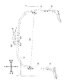
- FIG. 3 is an enlarged view of a region B in FIG. 2.
- FIG. 1 is a left side view of a rice transplanter 1 according to the present embodiment.
- the left side in the traveling direction (left direction in FIG. 1) of the traveling machine body 2 is simply referred to as the left side
- the right side in the traveling direction is simply referred to as the right side.
- the rice transplanter 1 includes a traveling machine body 2, a pair of left and right front wheels 3 and 3 and a pair of left and right rear wheels 4 and 4 that support the traveling machine body 2, and an engine 5 mounted on the front portion of the traveling machine body 2. Yes. Power from the engine 5 is transmitted to the rear transmission case 6 to drive the front wheels 3, 3 and the rear wheels 4, 4, so that the traveling machine body 2 travels forward and backward.
- a front axle case 7 projects from the left and right sides of the transmission case 6, and a front wheel 3 is attached to a front axle that extends outward from the front axle case 7 to the left and right.
- a cylindrical frame 8 protrudes behind the transmission case 6, a rear axle case 9 is fixed to the rear end side of the cylindrical frame 8, and the rear wheel 4 is attached to a rear axle that extends outward from the rear axle case 9 to the left and right. It has been.
- an operator boarding work step (vehicle body cover) 10 is provided on the upper surface side of the front and center portions of the traveling machine body 2.
- a bonnet 11 is disposed above the front part of the work step 10, and the engine 5 is installed inside the bonnet 11.
- the bonnet 11 covers the engine 5 and can be opened and closed.
- a steering handle 13 and a traveling main transmission lever 14 are provided in the driving operation unit 12 on the upper surface side of the rear portion of the bonnet 11.
- a control seat 16 is disposed behind the hood 11 via a seat frame 15.
- a handrail may be provided in the space between the control seat 16 and the steering handle 13. The handrail has a U-shape when viewed from the front, and both ends are fixed to the left and right floors of the bonnet 11. The height of the handrail is lower than the steering handle 13.
- a link frame 17 is erected at the rear end of the traveling machine body 2.
- a seedling planting device 21 is connected to the link frame 17 via an elevating link mechanism 20 including a lower link 18 and a top link 19 so as to be elevable.
- the cylinder base end side of the hydraulic lift cylinder 22 is supported on the rear upper surface of the cylindrical frame 8 so as to be vertically rotatable.
- the rod tip side of the lifting cylinder 22 is connected to the lower link 18.
- the operator gets on the work step 10 from the boarding / alighting step 23 on the side of the work step 10, and drives the seedling planting device 21 to plant seedlings in the field while moving in the field by driving operation. Perform work (rice planting work).
- the seedling planting device 21 includes a planting input case 24 to which power is transmitted from the engine 5 via the mission case 6, and four sets of eight strips connected to the planting input case 24 (in two strips).
- a set) of planting transmission cases 25 a seedling planting mechanism 26 provided on the rear end side of each planting transmission case 25, a seedling mounting base 27 for eight-row planting, and a lower surface side of each planting transmission case 25 And the float 28 for uniforming the surface.
- the seedling planting mechanism 26 is provided with a rotary case 30 having two planting claws 29 for one line. Two rotary cases 30 are arranged in the planting transmission case 25. By one rotation of the rotary case 30, the two planting claws 29 cut out and hold one seedling each and plant it on the field leveled by the float 28.
- a spare seedling stand 31 on which a spare seedling for supplying to the seedling planting device 21 can be placed is provided on the left and right sides of the bonnet 11.
- four spare seedling stands 31 are provided on the left and right.
- two spare seedling frames 32 that support the preliminary seedling stand 31 are provided on the left and right sides of the bonnet 11 at intervals in the front-rear direction.
- a connection frame 33 that is connected to the upper ends of two preliminary seedling frames 32 arranged in the front-rear direction is provided on the upper portion of the preliminary seedling frame 32.
- the connecting frame 33 is substantially L-shaped in a side view, and a support frame 34 extending upward is connected to the upper end of the connecting frame 33.
- a unit frame 35 is rotatably connected to the upper portions of the left and right support frames 34.
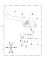
- FIG. 2 is a perspective view of the periphery of the unit frame 35 as viewed from the right rear.
- the unit frame 35 is substantially U-shaped when viewed from the front, and both ends of the unit frame 35 are rotatably connected to the support frame 34.
- a positioning unit 36 is fixed to the unit frame 35.
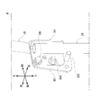
- FIG. 3A is an exploded perspective view of a region A of the support frame 34 and the unit frame 35 shown in FIG.
- a support plate 341 is provided at the upper end of the support frame 34.
- the support plate 341 has an L shape in plan view, and is fixed to the outer peripheral surface of the support frame 34 by welding.
- the support surface 341a on the inner side in the left-right direction of the support plate 341 is formed with three through holes, a first fixing hole 342, a positioning hole 343, and a rotation hole 344 from the top.
- the first fixing hole 342 is a hole for fixing the unit frame 35 to the support plate 341 with a bolt 345.
- the positioning hole 343 is a hole into which a positioning pin 353 (described later) provided in the unit frame 35 is inserted.
- the rotation hole 344 is a hole into which a rotation pin 354 (described later) provided in the unit frame 35 is inserted.
- a rotating plate 351 is provided at the lower end of the unit frame 35.
- the rotating plate 351 is fixed to the outer peripheral surface of the unit frame 35 by welding so as to face the support plate 341.
- a second fixing hole 352 is formed in the rotating plate 351.
- the unit frame 35 can be fixed to the support frame 34 by inserting bolts 345 into the first fixing holes 342 of the support plate 341 and the second fixing holes 352 of the rotating plate 351 and fastening them with nuts.
- the rotation plate 351 is provided with an L-shaped positioning pin 353.
- the tip of the positioning pin 353 is configured to protrude from the rotation plate 351 and be inserted into the positioning hole 343 of the support plate 341 (however, the tip of the positioning pin 353 is not visible in FIG. 3A).
- the positioning pin 353 is urged in a direction toward the support plate 341 (left direction in FIG. 3A), and the tip of the positioning pin 353 is pulled out of the positioning hole 343 by pulling the positioning pin 353 against the urging force. Can do.
- the rotation plate 351 is formed with a rotation pin 354 that protrudes toward the support plate 341.
- the rotation pin 354 is inserted into the rotation hole 344 of the support plate 341 and functions as a rotation axis. That is, the rotation plate 351 rotates with respect to the support plate 341 around the rotation pin 354.
- the unit frame 35 can be rotated with respect to the support frame 34 around the rotation shaft 35a in the left-right direction shown in FIG. 2, and the use state shown in FIG. 1 and the storage state shown in FIG. The state can be changed.
- the positioning unit 36 is located above the upper end of the support frame 34 in the use state, and is located below the upper end of the support frame 34 in the stored state. In the storage state shown in FIG. 4, the positioning unit 36 and the bonnet 11 overlap in a plan view, and the bonnet 11 can be opened and closed.
- the bolt 345 When rotating the rotation plate 351 from the state shown in FIG. 2, the bolt 345 is removed, and then the positioning pin 353 is pulled rightward to be removed from the positioning hole 343.
- the rotation plate 351 when the rotation plate 351 is fixed to the support plate 341, it can be fixed with the bolts 345 after positioning with the positioning pins 353 and the positioning holes 343, so that it can be fixed easily and safely. it can.
- the rotating pin 354 is formed with a male screw so that the nut is loosened when rotating, and the nut is completely tightened when fixed.
- FIG. 3B is an enlarged view of a region B of the support frame 34 and the unit frame 35 shown in FIG. Since the right rotation part has substantially the same structure as the left rotation part described above, only different parts will be described.
- a stopper pin 355 (corresponding to a restricting portion) is formed on the right rotation plate 351 instead of the positioning pin 353.
- the stopper pin 355 protrudes in the direction toward the support frame 34 (the right direction in FIG. 3B), and the unit frame 35 in use rotates to the rear side of the traveling machine body 2 by contacting the rear portion of the support frame 34. To regulate. Further, the stopper pin 355 abuts on the rear portion of the support plate 341, thereby restricting the unit frame 35 in the retracted state from rotating to the rear side of the traveling machine body 2.
- a positioning unit 36 is provided at the center in the left-right direction of the unit frame 35.
- the positioning unit 36 includes a positioning antenna, a position information receiver, an inertial measurement device (IMU), and the like.
- the positioning antenna receives a signal from a positioning satellite constituting a positioning system such as a satellite positioning system (GNSS).
- GNSS satellite positioning system
- the positioning antenna is attached to the upper surface of the positioning unit 36.
- the positioning signal received by the positioning antenna is input to the position information receiver, and the position information receiver processes the input positioning signal to obtain positioning information.
- the inertial measurement device is a unit that can specify the posture (roll angle, pitch angle, yaw angle) of the traveling machine body 2.
- the satellite positioning information of the rice transplanter 1 is corrected by correction information from a reference station installed at a predetermined reference point, and the current position of the rice transplanter 1 is obtained.
- the positioning method can be applied.
- various positioning methods such as D-GPS positioning (differential GPS positioning) and RTK positioning (real-time kinematic positioning) can be applied.
- RTK positioning is applied.
- a water intrusion prevention plate 360 is provided at the bottom of the positioning unit 36.
- the water intrusion prevention plate 360 is a plate member that is bent so as to protrude downward.
- the bent part 360 a of the water intrusion prevention plate 360 is located on the front side of the center of the positioning unit 36 in the front-rear direction. Thereby, it is difficult for water droplets dripping from the water intrusion prevention plate 360 to hit the tablet 37 described later.
- the water intrusion prevention plate 360 prevents water from entering from the drain hole provided in the bottom surface of the positioning unit 36.
- FIG. 5 is a perspective view of the periphery of the driving operation unit 12.
- a tablet 37 having a touch panel is provided on the right side of the driving operation unit 12.
- the tablet 37 can display the position information acquired by the positioning unit 36.
- the tablet 37 is used for displaying a travel route or instructing automatic travel when the rice transplanter 1 automatically travels along a set route, for example.
- the tablet 37 is supported by a tablet stay 38 as shown in FIG.
- the tablet stay 38 has a folding structure including a base end portion 38 a fixed to the preliminary seedling frame 32 and a tip end portion 38 b that rotates in the horizontal direction with respect to the base end portion 38 a.
- the tip end portion 38 b supports the tablet 37.
- the base end portion 38a of the tablet stay 38 is disposed between the front and rear spare seedling frames 32.
- a storage box 39 is provided on the upper surface of the base end portion 38 a of the tablet stay 38.
- the storage box 39 is disposed between the front and rear spare seedling frames 32 and between the upper and lower spare seedling stands 31.
- the bottom surface of the storage box 39 is fixed to the top surface of the base end portion 38a of the tablet stay 38 at the center in the left-right direction.
- the storage box 39 is waterproof and stores electronic devices such as communication devices.
- a hole (not shown) for drawing in a harness for connecting an electronic device is provided on the bottom surface of the storage box 39.
- the hole is provided with waterproof rubber.
- the base end 38 a is provided with a stopper 381 for preventing the tablet 37 from interfering with the storage box 39 when the tablet stay 38 is folded.
- the tip of the stopper 381 comes into contact with the back surface of the tip portion 38b.
- a holder 382 is provided at the tip of the tip portion 38b to sandwich and fix the tablet 37 from above and below.
- the holder 382 includes a holder lower part 382a fixed to the tip end part 38b and a holder upper part 382b biased toward the holder lower part 382a.
- the tablet 37 placed on the holder lower part 382a is sandwiched and fixed by the holder upper part 382b.
- a lateral slip prevention plate 382c for preventing the tablet 37 from laterally slipping is provided. Since the lateral slip prevention plate 382c is provided in the holder lower portion 382a, the terminal of the tablet 37 fixed to the holder 382 can be easily accessed. Further, the holder upper portion 382b may be provided with a sun visor for tablets in order to improve visibility. The holder lower portion 382a may be provided with a wireless charging function capable of charging the tablet 37.
- the vehicle position information is stored in the inertial measurement device (IMU) in the positioning unit 36.
- IMU inertial measurement device
- the IMU reset switch is preferably provided in the hood 11.
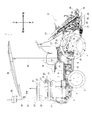
- FIG. 7 is a left side view of the rice transplanter 1 on which the sun visor 40 is mounted.
- the sun visor 40 is supported by a first sun visor frame 41 and a second sun visor frame 42.
- the first sun visor frame 41 supports the front part of the sun visor 40
- the second sun visor frame 42 supports the rear part of the sun visor 40.
- the unit frame 35 is rotatably connected to the middle part of the left and right first sun visor frames 41. That is, the positioning unit 36 and the unit frame 35 are moved in the left-right direction between a use state positioned above the upper end of the first sun visor frame 41 and a storage state positioned below the upper end of the first sun visor frame 41. Therefore, the positioning unit 36 and the unit frame 35 do not collide with the sun visor 40.
- the rice transplanter 1 includes a sun visor 40, a first sun visor frame 41 (corresponding to the support frame of the present invention) that supports the sun visor 40, and a middle portion of the first sun visor frame 41. And a positioning unit 36 that is supported by the unit frame 35 and obtains position information of the airframe, and the positioning unit 36 is located above the front end of the sun visor 40. In a use state located forward in the direction and in a retracted state below the use state and below the front end of the sun visor 40. It can be changed.
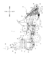
- FIG. 8 is a plan view of the rice transplanter 1 according to the second embodiment.
- the tablet 37 is disposed so as to overlap the sun visor 40 in plan view. This is effective in preventing the tablet 37 from rain, and further improves visibility by suppressing sunlight reflection.
- the tablet 37 is arranged on the front side of the straight line L connecting the rear end in the left-right direction of the preliminary seedling stand 31 and the outer end of the control seat 16. Thereby, when the seedling in the preliminary seedling stand 31 is replenished to the seedling placing stand 27, the tablet 37 does not get in the way. Furthermore, even in the state where the tablet stay 38 is folded and the tablet 37 is stored in front of the preliminary seedling table 31, the passage in front of the preliminary seedling table 31 has a width that allows passage. The same applies to the first embodiment and the third embodiment described later.
- ⁇ Third Embodiment> 9 and 10 show a form in which one spare seedling frame 32, 32 is provided on each of the left and right sides of the bonnet 11, and eight spare seedling stands 31 are provided on each spare seedling frame 32.
- FIG. The preliminary seedling stand 31 is configured to be rotatable about the preliminary seedling frame 32.
- the support member 43 that supports the unit frame 35 is provided.
- the support member 43 is erected from the floor on the right side of the bonnet 11. By providing the support member 43, the unit frame 35 is reinforced, and the vibration isolation effect of the positioning unit 36 is obtained.
- the arrangement of the support member 43 is not limited to the above-described configuration, and may be an arrangement standing from the floor on the left side of the bonnet 11.
- the tablet 37 is fixed to a holder 382 provided on the support member 43.
- the support member 43 can also be used as a route for electrical wiring connected to the positioning unit 36 and the tablet 37.
- the support member 43 can also be used as a handrail.
- the support frame 34 and the first sun visor frame 41 are connected to the connection frame 33, but the support frame 34 and the first sun visor frame 41 are integrated with the connection frame 33. Also good. Further, as in the third embodiment, the support frame 34 may be directly connected to the preliminary seedling frame 32 without the connection frame 33 interposed therebetween.
- FIG. 11 is a perspective view of the periphery of the unit frame 35 according to the fourth embodiment as viewed from the right rear.
- the unit frame 35 is substantially U-shaped when viewed from the front, and both ends of the unit frame 35 are rotatably connected to the support frame 34.
- a positioning unit 36 is fixed to the unit frame 35.
- the positioning unit 36 of the fourth embodiment has a first storage state and a second storage state as storage states.
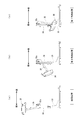
- the positioning unit 36 has a use state shown in FIG. 12A, a first storage state shown in FIG. 12C, and a first storage state shown in FIG. 12B located between the first storage state and the use state.
- the state can be changed between two storage states.
- the first storage state is rotated by 160 ° from the use state
- the second storage state is rotated by 115 ° from the use state.
- the positioning unit 36 is positioned above the upper end of the support frame 34 in the use state, and is positioned below the upper end of the support frame 34 in the first storage state and the second storage state.
- the positioning unit 36 is configured to be fixed in the second storage state.
- the first storage state is a state in which the rice transplanter 1 is not used
- the second storage state is a state in which the rice transplanter 1 that does not require the positioning unit 36 is operated, and the position of the positioning unit 36 is appropriately set according to the work. It becomes possible to change to.
- the visibility from the operator sitting on the control seat 16 can be improved as compared with the first storage state.
- FIG. 13A is an exploded perspective view of a C region of the support frame 34 and the unit frame 35 shown in FIG.
- a support plate 341 is provided at the upper end of the support frame 34.
- the support plate 341 has an L shape in plan view, and is fixed to the outer peripheral surface of the support frame 34 by welding.
- the first fixing hole 342 is a hole for fixing the unit frame 35 to the support plate 341 with a bolt 345.
- the first positioning hole 343a, the second positioning hole 343b, and the third positioning hole 343c are holes into which positioning pins 353 (described later) provided in the unit frame 35 are inserted.
- the rotation hole 344 is a hole into which a rotation pin 354 (described later) provided in the unit frame 35 is inserted.
- a rotating plate 351 is provided at the lower end of the unit frame 35.
- the rotating plate 351 is fixed to the outer peripheral surface of the unit frame 35 by welding so as to face the support plate 341.
- the rotation plate 351 is formed with a second fixing hole 352a, a third fixing hole 352b, and a fourth fixing hole 352c.
- a bolt 345 is inserted into the first fixing hole 342 of the support plate 341 and the second fixing hole 352a, the third fixing hole 352b, or the fourth fixing hole 352c of the rotating plate 351, and fastened with a nut.
- the unit frame 35 can be fixed to the support frame 34.
- the unit frame 35 is fixed to the support frame 34 using the second fixing holes 352a.
- the unit frame 35 In the first retracted state of the positioning unit 36, the unit frame 35 is fixed to the support frame 34 using the third fixing hole 352b. In the second storage state of the positioning unit 36, the unit frame 35 is fixed to the support frame 34 using the fourth fixing holes 352c.
- the rotation plate 351 is provided with an L-shaped positioning pin 353.
- the tip of the positioning pin 353 is configured to protrude from the rotation plate 351 and be inserted into the first positioning hole 343a, the second positioning hole 343b, or the third positioning hole 343c of the support plate 341 (however, FIG. In 13A, the tip of the positioning pin 353 is not visible).
- the positioning pin 353 is inserted into the first positioning hole 343a.
- the positioning pin 353 In the second storage state of the positioning unit 36, the positioning pin 353 is inserted into the second positioning hole 343b. In the first retracted state of the positioning unit 36, the positioning pin 353 is inserted into the third positioning hole 343c.
- the positioning pin 353 is urged in a direction toward the support plate 341 (left direction in FIG. 13A), and the positioning pin 353 is pulled against the urging force so that the tip of the positioning pin 353 is moved to the first positioning hole 343a, It can be extracted from the second positioning hole 343b or the third positioning hole 343c.
- the rotation plate 351 is formed with a rotation pin 354 that protrudes toward the support plate 341.
- the rotation pin 354 is inserted into the rotation hole 344 of the support plate 341 and functions as a rotation axis. That is, the rotation plate 351 rotates with respect to the support plate 341 around the rotation pin 354.
- the unit frame 35 can be rotated with respect to the support frame 34 about the rotation shaft 35a in the left-right direction shown in FIG. 11, and the use state shown in FIG.
- the state can be changed between two storage states.
- the positioning unit 36 is positioned above the upper end of the support frame 34 in the use state, and is positioned below the upper end of the support frame 34 in the first storage state and the second storage state. In the first retracted state, the positioning unit 36 and the bonnet 11 overlap in a plan view, and the bonnet 11 can be opened and closed.
- the bolt 345 When rotating the rotating plate 351 from the state shown in FIG. 11, the bolt 345 is removed, and then the positioning pin 353 is pulled rightward and pulled out from the first positioning hole 343a.
- the positioning pin 353 is positioned with the first positioning hole 343a, the second positioning hole 343b, or the third positioning hole 343c, and then the bolt 345 is used. Since it can be fixed, it can be fixed safely and easily.
- the rotating pin 354 is formed with a male screw so that the nut is loosened when rotating, and the nut is completely tightened when fixed.
- FIG. 13B is an enlarged view of the D region of the support frame 34 and the unit frame 35 shown in FIG. Since the right rotation part has substantially the same structure as the left rotation part described above, only different parts will be described.
- a stopper pin 355 (corresponding to a restricting portion) is formed on the right rotation plate 351 instead of the positioning pin 353.
- the stopper pin 355 protrudes in the direction toward the support frame 34 (the right direction in FIG. 13B), and the unit frame 35 in use rotates to the rear side of the traveling machine body 2 by contacting the rear portion of the support frame 34. To regulate. Further, the stopper pin 355 abuts against the rear portion of the support plate 341, thereby restricting the unit frame 35 in the first retracted state from rotating to the rear side of the traveling machine body 2.
- a positioning unit 36 is provided at the center in the left-right direction of the unit frame 35.
- the positioning unit 36 includes a positioning antenna, a position information receiver, an inertial measurement device (IMU), and the like.
- the positioning antenna receives a signal from a positioning satellite constituting a positioning system such as a satellite positioning system (GNSS).
- GNSS satellite positioning system
- the positioning signal received by the positioning antenna is input to the position information receiver, and the position information receiver processes the input positioning signal to obtain positioning information.
- the inertial measurement device is a unit that can specify the posture (roll angle, pitch angle, yaw angle) of the traveling machine body 2.
- the satellite positioning information of the rice transplanter 1 (mobile station) is corrected by correction information from a reference station installed at a predetermined reference point, and the current position of the rice transplanter 1 is obtained.
- the positioning method can be applied.
- various positioning methods such as D-GPS positioning (differential GPS positioning) and RTK positioning (real-time kinematic positioning) can be applied.
- D-GPS positioning is applied.
- FIG. 14 is a perspective view of the positioning unit 36
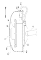
- FIG. 15 is a cross-sectional view of the positioning unit 36, partly cut at the center in the left-right direction.
- the positioning unit 36 includes a positioning device 361 and a case portion 362 that houses the positioning device 361 therein.
- the positioning device 361 can perform D-GPS positioning.
- the positioning device 361 and the case portion 362 are fastened by bolts from the lower surface of the flat base seat 363.
- the base seat 363 is fixed to the unit frame 35.
- the case part 362 has a box shape with an open bottom.
- the lower outer edge of the case portion 362 covers the periphery of the base seat 363.
- a notch 362c is formed in the lower part of the rear wall of the case portion 362, and a grommet 364 is fitted in the notch 362c.
- Grommet 364 supports harness 361a extending from positioning device 361 to the outside of case portion 362.
- a drain hole 362a is formed on the upper surface of the front portion of the case portion 362 in the used state.
- a concave portion 362b extending in the front-rear direction is provided on the upper surface of the case portion 362.
- the recess 362b is configured so that the rear side is deeper than the front side, and the drain hole 362a is formed in the rear wall of the recess 362b.
- the opening of the drain hole 362a faces forward and does not face upward. This makes it difficult for rain to enter the case portion 362 from the drain hole 362a when the positioning unit 36 is in use.
- a drain hole 363a is formed in the front portion of the base seat 363. Thereby, rain can be discharged from the drainage hole 363a even when rain enters the case portion 362 from the drainage hole 362a in the use state.
Landscapes
- Life Sciences & Earth Sciences (AREA)
- Soil Sciences (AREA)
- Environmental Sciences (AREA)
- Engineering & Computer Science (AREA)
- Transplanting Machines (AREA)
- Guiding Agricultural Machines (AREA)
- Mechanical Engineering (AREA)
- Chemical & Material Sciences (AREA)
- Combustion & Propulsion (AREA)
- Transportation (AREA)
Abstract
L'invention concerne une repiqueuse de riz 1 qui comprend : un corps de déplacement 2 ; un dispositif de plantation de semis 21 disposé derrière le corps de déplacement 2 ; des tables de semis supplémentaire gauche et droite 31 sur lesquelles un semis supplémentaire à fournir au dispositif de plantation de semis 21 peut être monté ; des cadres de support gauche et droit 34 s'étendant respectivement vers le haut à partir des tables de semis supplémentaire gauche et droite 31 ; un cadre unitaire 35 relié aux cadres de support gauche et droit 34 ; et une unité de télémétrie 36 qui est supportée sur le cadre unitaire 35 et acquiert des informations de position du corps de déplacement 2. L'unité de télémétrie 36 peut pivoter vers l'avant du corps autour d'un axe de pivotement gauche-droite 35a et peut ainsi commuter à un état d'utilisation, qui est positionné plus haut que l'extrémité supérieure des cadres de support 34, et un état rétracté qui est être positionné plus bas que l'extrémité supérieure des cadres de support 34.
Priority Applications (3)
| Application Number | Priority Date | Filing Date | Title |
|---|---|---|---|
| KR1020257013732A KR20250060947A (ko) | 2018-03-23 | 2019-03-19 | 이앙기 |
| KR1020207007792A KR20200132832A (ko) | 2018-03-23 | 2019-03-19 | 이앙기 |
| CN201980019677.0A CN111867353A (zh) | 2018-03-23 | 2019-03-19 | 插秧机 |
Applications Claiming Priority (4)
| Application Number | Priority Date | Filing Date | Title |
|---|---|---|---|
| JP2018-056172 | 2018-03-23 | ||
| JP2018056172 | 2018-03-23 | ||
| JP2019-035813 | 2019-02-28 | ||
| JP2019035813A JP7193379B2 (ja) | 2018-03-23 | 2019-02-28 | 田植機 |
Publications (1)
| Publication Number | Publication Date |
|---|---|
| WO2019181902A1 true WO2019181902A1 (fr) | 2019-09-26 |
Family
ID=67987659
Family Applications (1)
| Application Number | Title | Priority Date | Filing Date |
|---|---|---|---|
| PCT/JP2019/011329 Ceased WO2019181902A1 (fr) | 2018-03-23 | 2019-03-19 | Repiqueuse de riz |
Country Status (3)
| Country | Link |
|---|---|
| JP (1) | JP7510484B2 (fr) |
| KR (1) | KR20250060947A (fr) |
| WO (1) | WO2019181902A1 (fr) |
Families Citing this family (1)
| Publication number | Priority date | Publication date | Assignee | Title |
|---|---|---|---|---|
| WO2025142755A1 (fr) * | 2023-12-26 | 2025-07-03 | 株式会社クボタ | Repiqueuse |
Citations (7)
| Publication number | Priority date | Publication date | Assignee | Title |
|---|---|---|---|---|
| JPH0361818U (fr) * | 1989-10-17 | 1991-06-18 | ||
| JP2556588Y2 (ja) * | 1992-05-06 | 1997-12-03 | 石川島芝浦機械株式会社 | トラクターの安全フレーム装置 |
| JP2006071599A (ja) * | 2004-09-06 | 2006-03-16 | Mitsubishi Electric Engineering Co Ltd | 車両位置管理システム及び車両位置管理用車載装置 |
| WO2007054997A1 (fr) * | 2005-11-11 | 2007-05-18 | Universita Degli Studi Di Milano | Appareil de pose automatique d’elements discrets sur une surface cible et procede l’utilisant |
| JP2008092818A (ja) * | 2006-10-06 | 2008-04-24 | Yanmar Co Ltd | 農用作業車 |
| JP5772396B2 (ja) * | 2011-08-29 | 2015-09-02 | 井関農機株式会社 | 苗移植機 |
| JP2017112962A (ja) * | 2015-12-25 | 2017-06-29 | 株式会社クボタ | 作業車 |
Family Cites Families (4)
| Publication number | Priority date | Publication date | Assignee | Title |
|---|---|---|---|---|
| JP6408265B2 (ja) * | 2014-06-26 | 2018-10-17 | 株式会社クボタ | 水田作業機 |
| JP2019010060A (ja) * | 2017-06-30 | 2019-01-24 | 井関農機株式会社 | 苗移植機 |
| JP6858694B2 (ja) * | 2017-12-18 | 2021-04-14 | 株式会社クボタ | トラクタ |
| JP7193379B2 (ja) * | 2018-03-23 | 2022-12-20 | ヤンマーパワーテクノロジー株式会社 | 田植機 |
-
2019
- 2019-03-19 WO PCT/JP2019/011329 patent/WO2019181902A1/fr not_active Ceased
- 2019-03-19 KR KR1020257013732A patent/KR20250060947A/ko active Pending
-
2022
- 2022-12-08 JP JP2022196169A patent/JP7510484B2/ja active Active
Patent Citations (7)
| Publication number | Priority date | Publication date | Assignee | Title |
|---|---|---|---|---|
| JPH0361818U (fr) * | 1989-10-17 | 1991-06-18 | ||
| JP2556588Y2 (ja) * | 1992-05-06 | 1997-12-03 | 石川島芝浦機械株式会社 | トラクターの安全フレーム装置 |
| JP2006071599A (ja) * | 2004-09-06 | 2006-03-16 | Mitsubishi Electric Engineering Co Ltd | 車両位置管理システム及び車両位置管理用車載装置 |
| WO2007054997A1 (fr) * | 2005-11-11 | 2007-05-18 | Universita Degli Studi Di Milano | Appareil de pose automatique d’elements discrets sur une surface cible et procede l’utilisant |
| JP2008092818A (ja) * | 2006-10-06 | 2008-04-24 | Yanmar Co Ltd | 農用作業車 |
| JP5772396B2 (ja) * | 2011-08-29 | 2015-09-02 | 井関農機株式会社 | 苗移植機 |
| JP2017112962A (ja) * | 2015-12-25 | 2017-06-29 | 株式会社クボタ | 作業車 |
Also Published As
| Publication number | Publication date |
|---|---|
| KR20250060947A (ko) | 2025-05-07 |
| JP2023017005A (ja) | 2023-02-02 |
| JP7510484B2 (ja) | 2024-07-03 |
Similar Documents
| Publication | Publication Date | Title |
|---|---|---|
| JP2019165719A (ja) | 田植機 | |
| JP7736854B2 (ja) | 作業車両 | |
| US11780499B2 (en) | Working vehicle and tractor | |
| US20200398780A1 (en) | Tractor and Working Vehicle | |
| US8100212B2 (en) | Tractor | |
| JP7674541B2 (ja) | 作業車両 | |
| JP7510484B2 (ja) | 作業機 | |
| JP2021011139A (ja) | 作業車両におけるrtk−gnss受信装置 | |
| US20230347739A1 (en) | Display device and work vehicle | |
| JP7294990B2 (ja) | 作業車両 | |
| JP2012100603A (ja) | コンバイン | |
| JP7326176B2 (ja) | 移植機 | |
| JP4456498B2 (ja) | 作業車両の方向指示器取付構造 | |
| JP7591469B2 (ja) | 農作業機 | |
| JP2000014214A (ja) | 移動農機の機体カバー | |
| JP4036619B2 (ja) | 移植機 | |
| JPS6141638Y2 (fr) | ||
| JPH0631016B2 (ja) | 乗用型作業機械けん引車 | |
| AU2022386431B2 (en) | Riding mowing device | |
| JPS6141639Y2 (fr) | ||
| KR102746067B1 (ko) | 수전 작업기 | |
| JP2002002548A (ja) | キャビン | |
| JP2025171325A (ja) | 作業機械 | |
| JPH05153824A (ja) | 乗用型田植機の予備苗収容装置 | |
| JP2025171324A (ja) | 作業機械 |
Legal Events
| Date | Code | Title | Description |
|---|---|---|---|
| 121 | Ep: the epo has been informed by wipo that ep was designated in this application |
Ref document number: 19772517 Country of ref document: EP Kind code of ref document: A1 |
|
| NENP | Non-entry into the national phase |
Ref country code: DE |
|
| 122 | Ep: pct application non-entry in european phase |
Ref document number: 19772517 Country of ref document: EP Kind code of ref document: A1 |
|
| WWD | Wipo information: divisional of initial pct application |
Ref document number: 1020257013732 Country of ref document: KR |