WO2019187553A1 - Système de production d'énergie éolienne - Google Patents
Système de production d'énergie éolienne Download PDFInfo
- Publication number
- WO2019187553A1 WO2019187553A1 PCT/JP2019/002106 JP2019002106W WO2019187553A1 WO 2019187553 A1 WO2019187553 A1 WO 2019187553A1 JP 2019002106 W JP2019002106 W JP 2019002106W WO 2019187553 A1 WO2019187553 A1 WO 2019187553A1
- Authority
- WO
- WIPO (PCT)
- Prior art keywords
- pitch angle
- power generation
- generation system
- wind
- blade
- Prior art date
- Legal status (The legal status is an assumption and is not a legal conclusion. Google has not performed a legal analysis and makes no representation as to the accuracy of the status listed.)
- Ceased
Links
Images








Classifications
-
- F—MECHANICAL ENGINEERING; LIGHTING; HEATING; WEAPONS; BLASTING
- F03—MACHINES OR ENGINES FOR LIQUIDS; WIND, SPRING, OR WEIGHT MOTORS; PRODUCING MECHANICAL POWER OR A REACTIVE PROPULSIVE THRUST, NOT OTHERWISE PROVIDED FOR
- F03D—WIND MOTORS
- F03D7/00—Controlling wind motors
- F03D7/02—Controlling wind motors the wind motors having rotation axis substantially parallel to the air flow entering the rotor
- F03D7/04—Automatic control; Regulation
-
- Y—GENERAL TAGGING OF NEW TECHNOLOGICAL DEVELOPMENTS; GENERAL TAGGING OF CROSS-SECTIONAL TECHNOLOGIES SPANNING OVER SEVERAL SECTIONS OF THE IPC; TECHNICAL SUBJECTS COVERED BY FORMER USPC CROSS-REFERENCE ART COLLECTIONS [XRACs] AND DIGESTS
- Y02—TECHNOLOGIES OR APPLICATIONS FOR MITIGATION OR ADAPTATION AGAINST CLIMATE CHANGE
- Y02E—REDUCTION OF GREENHOUSE GAS [GHG] EMISSIONS, RELATED TO ENERGY GENERATION, TRANSMISSION OR DISTRIBUTION
- Y02E10/00—Energy generation through renewable energy sources
- Y02E10/70—Wind energy
- Y02E10/72—Wind turbines with rotation axis in wind direction
Definitions
- the present invention relates to a wind power generation system, and more particularly to a wind power generation system that reduces a decrease in power generation efficiency due to an increase in torsional deformation of a blade.
- a solar power generation system is common, but the output changes directly due to solar radiation, so output fluctuations are large and power generation cannot be performed at night.
- a wind power generation system can generate relatively stable power regardless of day or night by selecting and installing a place where wind conditions such as wind speed and direction are stable.
- a general large-scale wind power generation system includes a pitch drive device for adjusting the pitch angle and a power converter for adjusting the generator torque, and by adjusting the pitch angle and the generator torque, an arbitrary Control is performed to maximize the power output in the wind speed range.
- Patent Document 1 there is Patent Document 1.
- a measurement information input step for inputting measurement information of wind speed and direction of wind flowing into a wind turbine blade, and measurement information and torque input in the measurement information input step are stored in advance.
- Torque calculation to calculate the optimum torque calculated by the product of the actual torque generated in each blade element and the radial position, weight, and angular velocity of each blade element A difference between the generated torque and the optimum torque is reduced based on the step, a torque comparison step for comparing the generated torque calculated in the torque calculating step and the optimum torque, and a result of the comparison in the torque comparing step.
- the airflow generator, the pitch angle drive mechanism, and the yaw angle drive mechanism can be individually controlled in accordance with the features.
- the blades are becoming longer.
- the blades are attached to the leeward side, and the blades bend to the leeward side due to the wind load. Therefore, it is possible to make the blade longer and flexible in the upwind wind turbine (hereinafter, the longer and flexible blade is referred to as a longer and flexible blade).
- Patent Document 1 By applying the technology disclosed in Patent Document 1, it is possible to operate at a pitch angle that takes blade aerodynamic performance into account according to the wind speed, the rotational speed of the rotor or the generator, and improve the power generation efficiency.
- twist the amount of twist deformation (hereinafter referred to as twist) of the blade may increase.
- the blade aerodynamic performance is determined by the inflow relative wind speed determined by the wind speed and the rotational speed, and the blade angle (pitch angle and twist) in each cross section of the blade.
- the pitch angle that maximizes the aerodynamic performance is uniquely determined.
- Patent Document 1 when Patent Document 1 is applied to a long and flexible structure blade, it cannot be considered that the pitch angle that maximizes aerodynamic performance changes due to torsion compared to the case of applying it to a rigid structure blade with less torsion. There is a possibility of adjusting the pitch angle to decrease the efficiency. Further, since the azimuth angle is not used as an input value, the effect of wind shear in which the wind speed increases as the altitude increases cannot be considered. Furthermore, in the downwind wind turbine, the effect of the tower shadow, in which the wind speed decreases near the tower due to the influence of the tower, cannot be considered. Therefore, the effect of changes in wind speed during one rotation period cannot be considered, and power generation efficiency may be reduced.
- An object of the present invention is to provide an operation control means for improving the aerodynamic performance of the entire blade and improving the power generation efficiency by considering the twist.
- the present invention provides a wind power generation system including a blade that can change a pitch angle, a rotor that rotates by receiving wind from the blade, and a generator that generates electric power using the rotational energy of the rotor.
- the control device includes a control device for controlling the pitch angle, and the control device stores measurement information of wind speed, rotation speed of the rotor or generator, and pitch angle control information in consideration of blade twist calculated in advance.
- the wind power generation system is characterized in that the pitch angle is controlled based on the output of the database.
- a wind power generation system including a control device that can improve power generation efficiency by considering the twist of the blade.
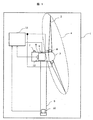
- FIG. 1 It is a figure which shows the component of the wind power generation system 1 when not implementing this invention. It is a block diagram which shows the process outline
- FIG. 1 It is a block diagram which shows the process outline
- FIG. It is a figure for demonstrating the fall of the aerodynamic performance in a certain blade cross section by the twist in the wind power generation system 1.
- FIG. It is a figure for demonstrating the relationship between the wind force and the force added to a rotation direction in the case where the database which concerns on 1st embodiment of this invention is applied, and the case where it does not apply.
- the wind power generation system 1 in FIG. 1 includes a rotor 4 that includes a plurality of blades 2 and a hub 3 that connects the plurality of blades 2.
- the rotor 4 is connected to the nacelle 5 via a rotating shaft (not shown in FIG. 1), and the position of the blade 2 can be changed by rotating.
- the nacelle 5 supports the rotor 4 rotatably. When the blade 2 receives wind, the rotor 4 rotates, and the rotational force of the rotor 4 rotates the generator 6 in the nacelle 5 to generate electric power.
- a wind direction / wind speed sensor 7 for measuring the wind direction and the wind speed is provided on the nacelle 5.
- Each blade 2 is provided with a pitch angle driving device 8 capable of adjusting the angle (pitch angle) of the blade 2 with respect to the wind.
- the pitch angle driving device 8 By using the pitch angle driving device 8, the wind energy (air volume) received by the blade 2 can be adjusted by changing the pitch angle, and the rotational energy of the rotor 4 with respect to the wind can be changed. This makes it possible to control the rotational speed and the generated power in a wide wind speed region.
- the nacelle 5 is installed on the tower 9 and has a mechanism (not shown) that can rotate with respect to the tower 9.
- the tower 9 supports the load of the blade 2 via the hub 3 and the nacelle 5 and is fixed to a base (not shown in the figure) installed at a predetermined position on the ground, offshore, and floating body.
- the generator 6 can control the torque generated by the generator (hereinafter referred to as “generator torque”) by the power converter 10 installed in the tower 9 and control the rotational torque of the rotor 4.
- the wind power generation system 1 includes a controller 11, and the controller 11 generates a generator based on the rotation speed output from the rotation speed sensor 12 that measures the rotation speed of the generator 6 and the generator torque of the generator 6. 6 and the pitch angle driving device 8 are adjusted to adjust the generated power and the rotational speed of the wind power generation system 1.
- the blade 2 can have a rotor diameter of, for example, 100 m or more. Further, when the rotor diameter is 180 m or more, the effect by the control corresponding to the flexible structure is particularly great.
- each blade element has an initial twist in terms of shape from the rotating surface of the blade 2, but the blade 2 web, spar cap, etc. are to be twisted by 0.2 ° or more due to the force applied by the wind during power generation operation. Can be designed. Further, in the case of a flexible structure blade that is twisted by 0.5 ° or more during power generation operation, a particularly remarkable effect can be obtained by the present embodiment control.
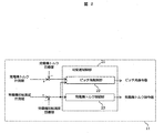
- FIG. 2 shows a block diagram of the variable speed control unit 21 mounted on the controller 11.
- the operation control means shown in FIG. 2 is a pitch angle control that determines a pitch angle command value by feedback control based on a deviation between a target value and a measured value of a generator torque, and a deviation between a target value and a measured value of a generator rotational speed.
- the unit 22 is provided.
- the generator torque control part 23 which determines a generator torque command value by feedback control based on the deviation of the target value of a generator rotational speed and a measured value is provided.
- FIG. 3 is a block diagram showing an outline of the pitch angle control unit 22 of the variable speed control unit 21.
- the pitch angle control unit 22 includes a rotation speed control unit 22a and a torque control unit 22b.
- the rotational speed control unit 22a determines the pitch angle command value by feedback control based on the deviation between the target value of the generator rotational speed and the measured value.
- the torque control part 22b determines a pitch angle command value by feedback control based on the deviation between the target value of the generator torque and the measured value. By adding these two values, the final pitch angle command value of the pitch angle control unit 22 is determined.
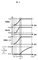
- FIG. 4 shows the characteristics of the wind power generation system 1 obtained by the operation control means mounted on the controller 11 shown in FIGS.
- FIG. 4 shows the relationship between the generated power with respect to the wind speed, the rotational speed of the generator, the generator torque, and the pitch angle.
- the horizontal axis of each graph shows the wind speed, and the wind speed increases toward the right side.
- the vertical axis of each graph indicates that the values of the generated power, the rotational speed, and the generator torque increase as going upward.
- the pitch angle the upper side is the feather (wind escape) side, and the lower side is the fine (wind receiving) side.
- Power generation is performed in a range from the cut-in wind speed Vin at which the rotor 4 starts to rotate to the cut-out wind speed Vout at which the rotation stops, and the generated power value increases as the wind speed increases until the wind speed Vd.
- the generated power is constant at the wind speed.
- the controller 11 controls the generator torque so that the rotational speed is constant (Wlow) from the cut-in wind speed Vin to the wind speed Va.
- the rated rotational speed Wrat is maintained.
- the generator torque and pitch angle are controlled. Basically, the generator torque is controlled to ensure the generated power.
- the generator torque is changed in accordance with the wind speed from the wind speed Vb to the wind speed Vd until the rated generator torque Qrat is reached. Holds the torque QRat.
- the pitch angle In the control of the pitch angle, the pitch angle is held at the fine angle ⁇ min up to the wind speed Vc, and the pitch angle is changed from the fine side ⁇ min to the feather side ⁇ max according to the wind speed in the range of the wind speed Vc to the cutout wind speed Vout.
- a reduction in power generation efficiency due to blade twisting in a wind speed region such as the cut-in wind speed Vin to the wind speed Vd, which is particularly required to improve the power generation efficiency, is prevented by adjusting the pitch angle. It is.
- FIG. 5 a is a block diagram showing an outline of the twist pitch angle command value calculation unit 100.
- the torsion pitch angle command value calculation unit 100 is based on the wind speed measurement unit 101, the rotation speed measurement unit 102 of the rotor or the generator, the yaw error measurement unit 103, the nacelle inclination angle measurement unit 104, and the azimuth angle measurement unit 105.
- the pitch angle command value or the correction value is determined from the database 106 storing the pitch angle control information that maximizes the aerodynamic performance in consideration of the above.
- the pitch angle maximizes the aerodynamic performance considering the torsion that occurs when the rotor 4 is inclined forward and backward. It is possible to adjust.
- the wind speed measuring means 101 measures the wind speed in the vicinity of the nacelle 5
- the effect of increasing the wind speed as the altitude increases, called wind shear cannot be considered.
- the effect of reducing the wind speed in the vicinity of the tower after passing through the tower called tower shadow in a downwind wind turbine cannot be considered. Therefore, by utilizing the azimuth angle measuring means 105, it is possible to consider a change in wind speed during one rotation period due to wind shear and tower shadow. Therefore, it is possible to adjust the pitch angle to maximize the aerodynamic performance in consideration of torsion during one rotation period.
- each blade can be set to independent pitch control.
- the values input to the database 106 from the wind speed measuring means 101, the rotational speed measuring means 102, the yaw error measuring means 103, and the nacelle inclination angle measuring means 104 match the output signals of the respective measuring means. It may be a value obtained by performing a filtering process in which a predetermined time constant is set.
- the pitch angle can be adjusted only by the twist pitch angle command value calculation unit 100 in FIG. 5a.
- the command value calculated by the twist pitch angle command value calculation unit 100 is used as the command value of the pitch angle control unit 22 of the wind power generation system 1.
- the final pitch angle command value may be determined by addition.
- the pitch angle control unit 22 may calculate the pitch angle command value by adding the command value from the rotation speed control unit and the command value from the torque control unit, or based only on the rotation speed control unit.
- the pitch angle command value may be calculated.
- FIG. 5b is a flowchart for creating in advance a database of pitch angles that maximizes aerodynamic performance considering torsion.
- step S100 parameters of wind speed, rotational speed, yaw error, nacelle tilt angle, and azimuth angle are input.
- step S101 an initial pitch angle value is input.
- step S102 based on the input values in steps S100 and S101, the torsional and aerodynamic performance of each blade element is calculated from the aerodynamics and physical model of the blade.
- step S103 it is determined whether or not a pitch angle that maximizes aerodynamic performance has been calculated. If not calculated, the pitch angle value is changed in step S101, and then the process of step S102 is performed again.
- step S104 it is determined whether or not the possible measurement information is covered. If not, the processes in steps S100 to S103 are executed again. As a result, the pitch angle that maximizes the aerodynamic performance in consideration of torsion is searched for the parameters covering the operating state of the wind turbine.
- step S105 the pitch angle that maximizes the aerodynamic performance in consideration of torsion is stored in the database for the parameters covering the operating state of the wind turbine.
- maximization of aerodynamic performance in the wind speed range from cut-in wind speed Vin to wind speed Vd, where improvement in power generation efficiency is required, maximizes the torque and force applied to the rotation direction of the entire blade.
- the quotient of the applied force and the force applied in the thrust direction of the entire blade is maximized, the lift of the entire blade is maximized, or the quotient of the lift and drag of the entire blade is maximized.
- maximization of aerodynamic performance during power generation operation such as wind speed Vd or higher, where blade load reduction is required, or during power standby during storms, depends on the force applied to the rotation direction of the entire blade and the thrust direction of the entire blade.
- the pitch angle that is referred to from the database based on the measurement conditions and maximizes the aerodynamic performance in consideration of torsion can be changed according to the wind speed region.
- FIG. 5c is a flowchart for creating in advance a generator torque database corresponding to a pitch angle that maximizes aerodynamic performance in consideration of torsion.
- step S106 parameters of wind speed, rotational speed, yaw error, nacelle tilt angle, azimuth angle, and pitch angle are input.
- step S107 the generated power and the generator torque are calculated.
- step S108 it is determined whether or not possible measurement information is covered. If not, the processes in steps S106 and S107 are executed again. As a result, the generator torque is searched for the parameters covering the operating state of the windmill.
- step S109 the generator torque corresponding to the pitch angle that maximizes the aerodynamic performance in consideration of torsion is added to the database storing the pitch angle and stored for the parameters covering the operating state of the windmill.
- the database 106 is obtained.
- the storage form of the database may be a table reference type or a function form.
- the function is created by fitting methods such as interpolation and exterior, or machine learning based on data from analysis and past operations. As a result, the amount of information stored in the database can be reduced.
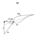
- FIG. 7 is a diagram for explaining the relationship between the angle of attack, the pitch angle, and the initial twist angle with respect to the relative wind speed flowing into the blade element of a certain blade cross section in the wind power generation system 1.
- FIG. 8 is a diagram for explaining a relationship when twisting occurs in FIG.
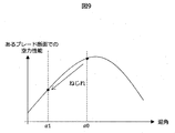
- FIG. 9 is a diagram showing the relationship between the angle of attack of the blade cross-section where a twist has occurred and the aerodynamic performance (cross-section aerodynamic performance) in the wind power generation system 1.
- the rotational speed ⁇ due to the rotation of the blade 107 and the relative wind speed W due to the wind speed V flow into the blade 107.
- the angle formed by the rotating surface of the blade 107 and the chord length is the sum of the pitch angle ⁇ p and the initial twist angle ⁇ s of the blade.
- the angle formed by the relative wind speed W and the chord length is the wing attack angle ⁇ 0.
- a twist ⁇ is added to the angle formed by the rotation surface and the chord length, and the angle of attack of the wing 107 changes to ⁇ 1. Therefore, as shown in FIG. 9, the cross-sectional aerodynamic performance of the blade 107 is lowered because it changes from ⁇ 0 to ⁇ 1.
- the cross-sectional aerodynamic performance is a force applied in the rotation direction of the blade 107 or a quotient of a force applied in the rotation direction of the blade 107 and a force applied in the thrust direction.
- FIG. 10 is a diagram showing an example of the relationship between the wind speed and the force applied in the rotation direction when the database according to the first embodiment of the present invention is applied and when the database is not applied.
- the force 109 applied in the rotation direction after the application of the database can be improved by about 10% on average with respect to the force 108 applied in the rotation direction before the application of the database.
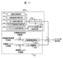
- FIG. 11 is a block diagram according to the second embodiment of the present invention.
- the torsional pitch angle command value calculation unit 200 includes azimuth angle correction value calculation means 201, and the azimuth angle correction value is input to the database 106, and the pitch angle command value is calculated from the database 106.
- the configuration is taken.
- the azimuth angle correction value calculation means 201 calculates a pitch angle command value by adding a value obtained by multiplying the value from the azimuth angle measurement means 105 by the time constant of the pitch angle driving device to the rotation speed by the rotation speed measurement means 102. Then, the azimuth angle is calculated by correcting the influence of the phase advance of the azimuth angle until the pitch angle command value is actually reached.
- FIG. 12 is a block diagram according to the third embodiment of the present invention.
- an inverse model 300 of the pitch angle driving device is provided, and the pitch angle command value corrected by the inverse model is added to the pitch angle command value in the first or second embodiment.
- the inverse model is created by obtaining an inverse transfer function of the pitch angle driving device 8 by analysis and machine learning based on past motion data.
- the calculation is performed based on the measurement information of the arrival time, which is caused by the variation of the measurement information from the calculation time of the pitch angle command value to the time when the pitch angle command value is actually reached. It is possible to correct an error between the pitch angle command value to be performed and the actual pitch angle at the arrival time by utilizing an inverse model, and it is possible to suppress a decrease in power generation efficiency.
- a pitch angle measuring unit 401 is provided, and a generator torque command value is calculated from the database 106 based on measurement information of the pitch angle measuring unit 401 in addition to the measuring unit.
- the value calculated from the database 106 may be used as the generator torque command value, or the final generator is obtained by adding the value calculated from the database 106 to the value calculated from the generator torque control unit 23.
- a torque command value may be determined.
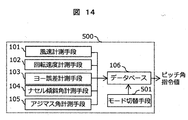
- mode switching means (mode switching function) 501 capable of switching between a power generation operation mode and a power generation standby mode is provided, and based on measurement information during power generation operation and power generation standby.
- the pitch angle that maximizes the aerodynamic performance considering the torsion to be referred to is changed. Further, since the rotation of the rotor or the generator is stopped during power generation standby, the rotational speed measuring means is not necessary for the measurement information.
- a pitch angle that maximizes the force applied in the rotational direction or minimizes the force applied in the thrust direction while maximizing the force applied in the rotational direction refers to a pitch angle that minimizes the force applied in the thrust direction.
- the addition unit of the command value from the torsion pitch angle command value calculation unit 200 and the command value of the pitch angle control unit 22 includes a weighting calculation unit 250, which adds the weights.
- k is a weighting factor
- ⁇ _ (ip_dem) is the pitch angle command value finally determined for the i-th blade
- ⁇ (p_conv) is the command value of the pitch angle control unit
- ⁇ (ip_opt) is the twist pitch angle
- V_1 and V_2 are calculated in advance based on the performance evaluation results.
- ⁇ Controls the aerodynamic maximum pitch angle with the derived k if the wind speed is less than V_1.
- the existing command value is added from the aerodynamic maximum pitch angle with a weight k, and when the wind speed is equal to or higher than V_2, the existing command value is controlled.
- SYMBOLS 1 Wind power generation system, 2 ... Blade, 3 ... Hub, 4 ... Rotor, 5 ... Nacelle, 6 ... Generator, 7 ... Wind direction wind speed sensor, 8 ... Pitch angle drive device, 9 ... Tower, 10 ... Power converter, DESCRIPTION OF SYMBOLS 11 ... Controller, 12 ... Rotation speed sensor, 21 ... Variable speed control part, 22 ... Pitch angle control part, 22a ... Rotation speed control part, 22b ... Torque control part, 23, Generator torque control part, 100 ... Twist pitch angle Command value calculation unit 101 ... Wind speed measuring means 102 ... Rotational speed measuring means 103 ... Yaw error measuring means 104 ...
- Nacelle inclination angle measuring means 105 ... Azimuth angle measuring means 106 ... Database 107 107 Wings 108 Force applied in the rotation direction before application of the database, 109 ... Force applied in the rotation direction after application of the database, 200 ... Azimuth angle correction torsion pitch angle command value calculation unit, 201 ... Zimuth angle correction value calculation means, 300 ... inverse model, 400 ... twist generator torque command value calculation section, 401 ... pitch angle measurement means, 500 ... mode switching twist pitch angle command value calculation section, 501 ... mode switching means
Landscapes
- Engineering & Computer Science (AREA)
- Life Sciences & Earth Sciences (AREA)
- Sustainable Development (AREA)
- Sustainable Energy (AREA)
- Chemical & Material Sciences (AREA)
- Combustion & Propulsion (AREA)
- Mechanical Engineering (AREA)
- General Engineering & Computer Science (AREA)
- Wind Motors (AREA)
- Control Of Eletrric Generators (AREA)
Abstract
La présente invention concerne un système de production d'énergie capable d'améliorer le rendement de production d'énergie. Le système de production d'énergie éolienne comprend : une pale ayant un angle de pas variable; un rotor qui reçoit le vent sur la pale et tourne; un générateur d'énergie qui utilise l'énergie de rotation du rotor pour générer de l'énergie; et un dispositif de commande qui commande l'angle de pas. Le dispositif de commande commande l'angle de pas sur la base de sorties provenant d'une base de données qui stocke : des informations de mesure concernant la vitesse du vent et la vitesse de rotation du rotor ou du générateur d'énergie; et des informations de commande d'angle de pas prenant en considération une torsion de pale pré-calculée.
Applications Claiming Priority (2)
| Application Number | Priority Date | Filing Date | Title |
|---|---|---|---|
| JP2018066603A JP2019178615A (ja) | 2018-03-30 | 2018-03-30 | 風力発電システム |
| JP2018-066603 | 2018-03-30 |
Publications (1)
| Publication Number | Publication Date |
|---|---|
| WO2019187553A1 true WO2019187553A1 (fr) | 2019-10-03 |
Family
ID=68061125
Family Applications (1)
| Application Number | Title | Priority Date | Filing Date |
|---|---|---|---|
| PCT/JP2019/002106 Ceased WO2019187553A1 (fr) | 2018-03-30 | 2019-01-23 | Système de production d'énergie éolienne |
Country Status (2)
| Country | Link |
|---|---|
| JP (1) | JP2019178615A (fr) |
| WO (1) | WO2019187553A1 (fr) |
Cited By (1)
| Publication number | Priority date | Publication date | Assignee | Title |
|---|---|---|---|---|
| CN113847211A (zh) * | 2020-06-28 | 2021-12-28 | 北京金风科创风电设备有限公司 | 风力发电机组的净空监测系统、方法及控制器 |
Citations (8)
| Publication number | Priority date | Publication date | Assignee | Title |
|---|---|---|---|---|
| JPS58178884A (ja) * | 1982-04-02 | 1983-10-19 | ユナイテツド・テクノロジ−ズ・コ−ポレイシヨン | 発電用風力タ−ビンシステム |
| JP2004301116A (ja) * | 2003-03-19 | 2004-10-28 | Mitsubishi Electric Corp | 風力発電システム |
| JP2015001212A (ja) * | 2013-06-18 | 2015-01-05 | 株式会社日立製作所 | 風力発電機の出力制御装置及び出力制御方法、並びに風力発電システム |
| EP2848805A1 (fr) * | 2013-09-17 | 2015-03-18 | Alstom Renovables España, S.L. | Procédé de fonctionnement d'une éolienne |
| JP2015532382A (ja) * | 2012-10-01 | 2015-11-09 | イエフペ エネルジ ヌヴェルIfp Energies Nouvelles | 入力風速の予測値を使用した風力タービン制御方法 |
| JP2016089732A (ja) * | 2014-11-06 | 2016-05-23 | 株式会社日立製作所 | 風力発電装置 |
| WO2017085156A1 (fr) * | 2015-11-18 | 2017-05-26 | Wobben Properties Gmbh | Commande d'une éolienne à pales de rotor réglables |
| US20170321660A1 (en) * | 2014-11-21 | 2017-11-09 | Vestas Wind Systems A/S | A method for estimating a wind speed including calculating a pitch angle adjusted for blade torsion |
-
2018
- 2018-03-30 JP JP2018066603A patent/JP2019178615A/ja active Pending
-
2019
- 2019-01-23 WO PCT/JP2019/002106 patent/WO2019187553A1/fr not_active Ceased
Patent Citations (8)
| Publication number | Priority date | Publication date | Assignee | Title |
|---|---|---|---|---|
| JPS58178884A (ja) * | 1982-04-02 | 1983-10-19 | ユナイテツド・テクノロジ−ズ・コ−ポレイシヨン | 発電用風力タ−ビンシステム |
| JP2004301116A (ja) * | 2003-03-19 | 2004-10-28 | Mitsubishi Electric Corp | 風力発電システム |
| JP2015532382A (ja) * | 2012-10-01 | 2015-11-09 | イエフペ エネルジ ヌヴェルIfp Energies Nouvelles | 入力風速の予測値を使用した風力タービン制御方法 |
| JP2015001212A (ja) * | 2013-06-18 | 2015-01-05 | 株式会社日立製作所 | 風力発電機の出力制御装置及び出力制御方法、並びに風力発電システム |
| EP2848805A1 (fr) * | 2013-09-17 | 2015-03-18 | Alstom Renovables España, S.L. | Procédé de fonctionnement d'une éolienne |
| JP2016089732A (ja) * | 2014-11-06 | 2016-05-23 | 株式会社日立製作所 | 風力発電装置 |
| US20170321660A1 (en) * | 2014-11-21 | 2017-11-09 | Vestas Wind Systems A/S | A method for estimating a wind speed including calculating a pitch angle adjusted for blade torsion |
| WO2017085156A1 (fr) * | 2015-11-18 | 2017-05-26 | Wobben Properties Gmbh | Commande d'une éolienne à pales de rotor réglables |
Cited By (1)
| Publication number | Priority date | Publication date | Assignee | Title |
|---|---|---|---|---|
| CN113847211A (zh) * | 2020-06-28 | 2021-12-28 | 北京金风科创风电设备有限公司 | 风力发电机组的净空监测系统、方法及控制器 |
Also Published As
| Publication number | Publication date |
|---|---|
| JP2019178615A (ja) | 2019-10-17 |
Similar Documents
| Publication | Publication Date | Title |
|---|---|---|
| US9372201B2 (en) | Yaw and pitch angles | |
| TWI708893B (zh) | 風力發電系統 | |
| CN102906418B (zh) | 风力涡轮机 | |
| US8025476B2 (en) | System and methods for controlling a wind turbine | |
| CN102465835B (zh) | 一种风力发电场以及控制其中风力机的方法 | |
| AU2007303956B2 (en) | Wind turbine with blade pitch control to compensate for wind shear and wind misalignment | |
| US9523352B2 (en) | Methods and systems for alleviating the loads generated in wind turbines by wind asymmetries | |
| EP2556248B1 (fr) | Éolienne | |
| US20130045098A1 (en) | Cyclic Pitch Control System for Wind Turbine Blades | |
| US20130300115A1 (en) | Systems and methods for optimizing power generation in a wind farm turbine array | |
| US9556850B2 (en) | Method of controlling a wind turbine | |
| NO342746B1 (no) | Fremgangsmåte for reduksjon av aksielle kraftvariasjoner i et vindkraftverk. | |
| US20180034394A1 (en) | Wind power generating system | |
| EP1597476A1 (fr) | Methode de commande de la charge aerodynamique d'une eolienne en fonction de la mesure de l'ecoulement local au niveau des pales | |
| JP2020139427A (ja) | 風力発電システム、風量発電システムの制御方法 | |
| EP4426933B1 (fr) | Procédé de réduction de charges de volet de pale dans une éolienne | |
| US20180328339A1 (en) | Control of a wind turbine having adjustable rotor blades | |
| KR102018579B1 (ko) | 풍력터빈 제어시스템의 피치제어기 | |
| KR102042259B1 (ko) | 풍력발전시스템 및 그것의 구동 정지 방법 | |
| JP2017044088A (ja) | 風力発電システム | |
| JP2019178615A (ja) | 風力発電システム | |
| JP2020002781A (ja) | 風力発電装置の制御方法 | |
| WO2024028232A1 (fr) | Pale d'éolienne, éolienne et procédé de fonctionnement d'une éolienne | |
| Bergami | Preliminary Evaluation with Feed-Forward Cyclic Control |
Legal Events
| Date | Code | Title | Description |
|---|---|---|---|
| 121 | Ep: the epo has been informed by wipo that ep was designated in this application |
Ref document number: 19778096 Country of ref document: EP Kind code of ref document: A1 |
|
| 122 | Ep: pct application non-entry in european phase |
Ref document number: 19778096 Country of ref document: EP Kind code of ref document: A1 |