WO2019187671A1 - Système de détection, dispositif de traitement d'informations, programme, et procédé de collecte d'informations - Google Patents
Système de détection, dispositif de traitement d'informations, programme, et procédé de collecte d'informations Download PDFInfo
- Publication number
- WO2019187671A1 WO2019187671A1 PCT/JP2019/004296 JP2019004296W WO2019187671A1 WO 2019187671 A1 WO2019187671 A1 WO 2019187671A1 JP 2019004296 W JP2019004296 W JP 2019004296W WO 2019187671 A1 WO2019187671 A1 WO 2019187671A1
- Authority
- WO
- WIPO (PCT)
- Prior art keywords
- odor
- unit
- information
- sensor
- odor sensor
- Prior art date
- Legal status (The legal status is an assumption and is not a legal conclusion. Google has not performed a legal analysis and makes no representation as to the accuracy of the status listed.)
- Ceased
Links
Images





Classifications
-
- G—PHYSICS
- G01—MEASURING; TESTING
- G01N—INVESTIGATING OR ANALYSING MATERIALS BY DETERMINING THEIR CHEMICAL OR PHYSICAL PROPERTIES
- G01N33/00—Investigating or analysing materials by specific methods not covered by groups G01N1/00 - G01N31/00
- G01N33/0004—Gaseous mixtures, e.g. polluted air
- G01N33/0009—General constructional details of gas analysers, e.g. portable test equipment
- G01N33/0027—General constructional details of gas analysers, e.g. portable test equipment concerning the detector
- G01N33/0031—General constructional details of gas analysers, e.g. portable test equipment concerning the detector comprising two or more sensors, e.g. a sensor array
-
- G—PHYSICS
- G01—MEASURING; TESTING
- G01N—INVESTIGATING OR ANALYSING MATERIALS BY DETERMINING THEIR CHEMICAL OR PHYSICAL PROPERTIES
- G01N25/00—Investigating or analyzing materials by the use of thermal means
- G01N25/20—Investigating or analyzing materials by the use of thermal means by investigating the development of heat, i.e. calorimetry, e.g. by measuring specific heat, by measuring thermal conductivity
- G01N25/48—Investigating or analyzing materials by the use of thermal means by investigating the development of heat, i.e. calorimetry, e.g. by measuring specific heat, by measuring thermal conductivity on solution, sorption, or a chemical reaction not involving combustion or catalytic oxidation
-
- G—PHYSICS
- G01—MEASURING; TESTING
- G01N—INVESTIGATING OR ANALYSING MATERIALS BY DETERMINING THEIR CHEMICAL OR PHYSICAL PROPERTIES
- G01N29/00—Investigating or analysing materials by the use of ultrasonic, sonic or infrasonic waves; Visualisation of the interior of objects by transmitting ultrasonic or sonic waves through the object
- G01N29/02—Analysing fluids
- G01N29/022—Fluid sensors based on microsensors, e.g. quartz crystal-microbalance [QCM], surface acoustic wave [SAW] devices, tuning forks, cantilevers, flexural plate wave [FPW] devices
-
- G—PHYSICS
- G01—MEASURING; TESTING
- G01N—INVESTIGATING OR ANALYSING MATERIALS BY DETERMINING THEIR CHEMICAL OR PHYSICAL PROPERTIES
- G01N33/00—Investigating or analysing materials by specific methods not covered by groups G01N1/00 - G01N31/00
- G01N33/0004—Gaseous mixtures, e.g. polluted air
- G01N33/0009—General constructional details of gas analysers, e.g. portable test equipment
- G01N33/0062—General constructional details of gas analysers, e.g. portable test equipment concerning the measuring method or the display, e.g. intermittent measurement or digital display
-
- G—PHYSICS
- G01—MEASURING; TESTING
- G01N—INVESTIGATING OR ANALYSING MATERIALS BY DETERMINING THEIR CHEMICAL OR PHYSICAL PROPERTIES
- G01N33/00—Investigating or analysing materials by specific methods not covered by groups G01N1/00 - G01N31/00
- G01N33/0004—Gaseous mixtures, e.g. polluted air
- G01N33/0009—General constructional details of gas analysers, e.g. portable test equipment
- G01N33/0062—General constructional details of gas analysers, e.g. portable test equipment concerning the measuring method or the display, e.g. intermittent measurement or digital display
- G01N33/0068—General constructional details of gas analysers, e.g. portable test equipment concerning the measuring method or the display, e.g. intermittent measurement or digital display using a computer specifically programmed
-
- G—PHYSICS
- G01—MEASURING; TESTING
- G01N—INVESTIGATING OR ANALYSING MATERIALS BY DETERMINING THEIR CHEMICAL OR PHYSICAL PROPERTIES
- G01N5/00—Analysing materials by weighing, e.g. weighing small particles separated from a gas or liquid
- G01N5/02—Analysing materials by weighing, e.g. weighing small particles separated from a gas or liquid by absorbing or adsorbing components of a material and determining change of weight of the adsorbent, e.g. determining moisture content
-
- G—PHYSICS
- G08—SIGNALLING
- G08C—TRANSMISSION SYSTEMS FOR MEASURED VALUES, CONTROL OR SIMILAR SIGNALS
- G08C15/00—Arrangements characterised by the use of multiplexing for the transmission of a plurality of signals over a common path
-
- G—PHYSICS
- G01—MEASURING; TESTING
- G01N—INVESTIGATING OR ANALYSING MATERIALS BY DETERMINING THEIR CHEMICAL OR PHYSICAL PROPERTIES
- G01N2291/00—Indexing codes associated with group G01N29/00
- G01N2291/02—Indexing codes associated with the analysed material
- G01N2291/025—Change of phase or condition
- G01N2291/0256—Adsorption, desorption, surface mass change, e.g. on biosensors
-
- G—PHYSICS
- G01—MEASURING; TESTING
- G01N—INVESTIGATING OR ANALYSING MATERIALS BY DETERMINING THEIR CHEMICAL OR PHYSICAL PROPERTIES
- G01N33/00—Investigating or analysing materials by specific methods not covered by groups G01N1/00 - G01N31/00
- G01N33/0004—Gaseous mixtures, e.g. polluted air
- G01N33/0009—General constructional details of gas analysers, e.g. portable test equipment
- G01N33/0073—Control unit therefor
Definitions
- the present invention relates to a sensing system, an information processing apparatus, a program, and an information collection method.
- odor sensor elements have been widely developed.
- a QCM (Quartz Crystal Microbalance) sensor in which a film that adsorbs an odor-causing substance is provided on the surface of a crystal resonator is known.
- the resonance frequency of the AT-cut quartz resonator changes due to mass change.
- the QCM sensor detects the mass of the causative substance by vibrating the AT-cut quartz crystal vibrator and detecting the amount of change in the resonance frequency.
- a sensor device including a plurality of odor sensor elements each detecting the mass of a different causative substance is also known.
- Such a sensor device can output the masses of a plurality of causative substances.
- the information processing apparatus receives the respective amounts of the plurality of causal substances output from the sensor device, and compares the received patterns of the amounts of the plurality of causal substances with the patterns registered in advance. Thereby, the information processing apparatus can specify the kind of odor.
- Such a sensor device can be applied to a system that collects many kinds of odors and creates a database of the collected odors. By collecting many kinds of odors and analyzing the collected many odors, for example, odors that have been judged by human senses so far can be handled as quantitative information.
- a sensor device including a plurality of odor sensor elements has a complicated circuit configuration, and various noises are included in detection signals. Therefore, when many kinds of odors are collected, a lot of noise is included in the information. In addition, when monitoring the odor, it is necessary to record a detection signal in a state where no odor is generated, and information cannot be collected efficiently.
- the present invention has been made in view of the above, and an object of the present invention is to provide a sensing system, an information processing apparatus, a program, and an information collecting method capable of collecting information about odors with high accuracy and efficiency.
- a sensing system includes a first odor sensor including at least one detection element that detects the amount of an odor-causing substance existing in the air, and an air
- a second odor sensor including a filter that removes the odor-causing substance present therein, at least one detection element that detects an amount of the odor-causing substance present in the air that has passed through the filter, and the first odor Difference between at least one first output signal detected by at least one detection element included in the sensor and at least one second output signal detected by the at least one detection element included in the second odor sensor And calculating the difference calculation unit for generating at least one detection signal, and the information generated based on the at least one detection signal as odor information And a collecting unit for collecting Te.
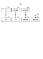
- FIG. 1 is a diagram illustrating a configuration of a sensing system.
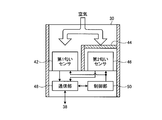
- FIG. 2 is a diagram illustrating an example of the configuration of the sensor unit.
- FIG. 3 is a diagram illustrating an example of the configuration of the first odor sensor.
- FIG. 4 is a diagram illustrating a functional configuration of the signal processing unit.
- FIG. 5 is a diagram illustrating an example of waveforms of a plurality of first output signals output from the first odor sensor.
- FIG. 6 is a diagram illustrating an example of waveforms of a plurality of second output signals output from the second odor sensor.
- FIG. 7 is a diagram illustrating an example of waveforms of a plurality of detection signals output from the difference calculation unit.
- FIG. 8 is a diagram illustrating a functional configuration of the information collection unit.
- FIG. 9 is a diagram for explaining the odor determination process.
- FIG. 10 is a diagram illustrating an example of waveforms, start timings, and end timings of a plurality of detection signals.
- FIG. 11 is a diagram illustrating an example of information registered in the information storage unit.
- FIG. 12 is a flowchart showing the flow of processing of the information collection unit.
- FIG. 13 is a diagram illustrating a configuration of a sensing system according to a modification.
- FIG. 14 is a flowchart illustrating a process flow of the information collection unit according to the modification.
- FIG. 15 is a diagram illustrating a hardware configuration of the information processing apparatus.
- the sensing system 10 continuously monitors odors and stores odor information related to odors obtained by the monitoring.
- FIG. 1 is a diagram showing a configuration of the sensing system 10.
- the sensing system 10 includes a sensor unit 30, a temperature sensor 32, a humidity sensor 34, an information storage unit 36, a signal processing unit 38, and an information collection unit 40.
- the sensor unit 30 includes a first odor sensor 42, a filter 44, and a second odor sensor 46.
- the first odor sensor 42 includes at least one detection element that detects the amount of odor-causing substances present in the air.
- Each detection element detects the mass of the causative substance as the amount of the causative substance of the odor.
- each detection element may detect the volume or molecular weight of the causative substance as the amount of the causative substance.
- each of the plurality of detection elements is a different type of element.
- any two detection elements included in the first odor sensor 42 detect the amounts of odor-causing substances of different types.
- the first detection element detects the amount of the substance X
- the second detection element detects the amount of the substance Y.
- any two detection elements included in the first odor sensor 42 may detect the amount of the same kind of odor causing substance with different sensitivities.
- the first detection element detects the amount of the substance X with a first sensitivity
- the second detection element detects the amount of the substance X with a second sensitivity lower than the first sensitivity.
- any two detection elements included in the first odor sensor 42 may detect the amounts of a plurality of odor-causing substances of different types of combinations.
- the first detection element detects the total amount of the substance X and the substance Y
- the second detection element detects the total amount of the substance X and the substance Z.
- any two detection elements included in the first odor sensor 42 may detect the amounts of a plurality of odor-causing substances of the same type of combination with different sensitivities.
- the first detection element detects the total amount of the substance X and the substance Y with a first sensitivity
- the second detection element has a total amount of the substance X and the substance Y lower than the first sensitivity. Detection may be performed with the second sensitivity.
- the filter 44 is provided in front of the second odor sensor 46.
- the filter 44 removes odor-causing substances present in the air given to the second odor sensor 46.
- the second odor sensor 46 includes at least one detection element that detects the amount of odor-causing substances present in the air that has passed through the filter 44.
- the second odor sensor 46 has the same configuration as the first odor sensor 42. Accordingly, the first odor sensor 42 and the second odor sensor 46 include at least one detection element of the same type.
- Such a sensor unit 30 transmits at least one first output signal detected by at least one detection element included in the first odor sensor 42 to the signal processing unit 38. Further, the sensor unit 30 transmits at least one second output signal detected by at least one detection element included in the second odor sensor 46 to the signal processing unit 38.
- the first odor sensor 42, the filter 44 and the second odor sensor 46 are arranged in the vicinity.
- the first odor sensor 42 and the second odor sensor 46 may be disposed in the same casing or may be provided independently of each other.
- the temperature sensor 32 is provided in the vicinity of the first odor sensor 42 and the second odor sensor 46.
- the temperature sensor 32 detects the temperature around the first odor sensor 42 and the second odor sensor 46.
- the temperature sensor 32 transmits a temperature signal representing the temperature around the first odor sensor 42 and the second odor sensor 46 to the signal processing unit 38.
- the humidity sensor 34 is provided in the vicinity of the first odor sensor 42 and the second odor sensor 46.
- the humidity sensor 34 detects the humidity around the first odor sensor 42 and the second odor sensor 46.
- the humidity sensor 34 transmits a humidity signal representing the humidity around the first odor sensor 42 and the second odor sensor 46 to the signal processing unit 38.
- the information storage unit 36 stores odor information related to each odor generated.
- the signal processing unit 38 includes at least one first output signal detected by at least one detection element included in the first odor sensor 42 and at least detected by at least one detection element included in the second odor sensor 46. A difference from one second output signal is calculated to generate at least one detection signal. The signal processing unit 38 calculates a difference between the first output signal and the second output signal between the detection elements of the same type, and generates a detection signal. Further, the signal processing unit 38 corrects at least one detection signal based on the temperature signal transmitted from the temperature sensor 32 and the humidity signal transmitted from the humidity sensor 34. The signal processing unit 38 transmits at least one detection signal to the information collecting unit 40. The signal processing unit 38 will be further described with reference to FIG.
- the information collection unit 40 When the odor is generated in the air, the information collection unit 40 generates odor information related to the odor generated in the air based on at least one detection signal transmitted from the signal processing unit 38. The information collection unit 40 writes the generated odor information in the information storage unit 36. The information collecting unit 40 will be further described with reference to FIG.
- FIG. 2 is a diagram illustrating an example of the configuration of the sensor unit 30.
- the sensor unit 30 includes a first odor sensor 42, a filter 44, a second odor sensor 46, a communication unit 48, and a control unit 50.
- the first odor sensor 42 and the second odor sensor 46 are disposed in the same casing, for example.
- the first odor sensor 42 is given air that has not passed through the filter 44.
- the first odor sensor 42 outputs at least one first output signal representing the odor in the air that has not passed through the filter 44.
- the second odor sensor 46 is given air that has passed through the filter 44.
- the second odor sensor 46 outputs at least one second output signal representing the odor in the air that has passed through the filter 44.
- the communication unit 48 transmits at least one first output signal output from the first odor sensor 42 to the signal processing unit 38. In addition, the communication unit 48 transmits at least one second output signal output from the second odor sensor 46 to the signal processing unit 38.
- the control unit 50 manages and controls the operations of the first odor sensor 42, the second odor sensor 46, and the communication unit 48.
- the configuration of the sensor unit 30 is an example, and any configuration may be used.
- FIG. 3 is a diagram illustrating an example of the configuration of the first odor sensor 42.
- the first odor sensor 42 is a QCM sensor that can detect the mass of a minute substance contained in air.
- the first odor sensor 42 is not limited to the QCM sensor, and may be a sensor of another type such as a gas sensor using a semiconductor thin film.
- the second odor sensor 46 has the same configuration as the first odor sensor 42.
- the first odor sensor 42 includes a support portion 58, a plurality of gas detection elements 60, and a drive detection circuit 62.
- a plurality of gas detection elements 60 are attached to the support portion 58.
- the gas detection element 60 is an example of a detection element.
- the first odor sensor 42 has six different types of gas detection elements 60-A to 60-F.
- each of the six gas detection elements 60-A to 60-F detects a different type of odor causing substance.
- Each of the gas detection elements 60 is provided on at least one of the crystal resonator cut so as to be able to vibrate by the piezoelectric effect, two electrodes provided on both sides of the crystal resonator, and the plane of the crystal resonator.
- An adsorption film is provided on at least one of the crystal resonator cut so as to be able to vibrate by the piezoelectric effect, two electrodes provided on both sides of the crystal resonator, and the plane of the crystal resonator.
- Quartz vibrator is partly held on the support 58 so that part of the side surface can vibrate.
- An AC voltage is applied to the two electrodes from the drive detection circuit 62.
- the adsorption film adsorbs a specific causative substance present in the surrounding air.
- Each of the plurality of gas detection elements 60 includes an adsorption film that adsorbs different substances. Specifically, each of the plurality of gas detection elements 60 includes an adsorption film that adsorbs a causative substance to be detected by the sensor unit 30.
- the crystal resonator vibrates due to the piezoelectric effect.
- the fundamental resonance frequency of the crystal unit is determined by mass and viscoelasticity. Therefore, when the causative substance is adsorbed on the adsorption film and the mass changes, the basic resonance frequency of the gas detection element 60 changes according to the change in the mass of the adsorbed substance.
- the drive detection circuit 62 detects a change in the basic resonance frequency of each of the plurality of gas detection elements 60 by applying an AC voltage to each of the plurality of gas detection elements 60 under the control of the control unit 50. Thereby, the drive detection circuit 62 can detect the mass of the odor causing substance contained in the given air for each of the plurality of gas detection elements 60.
- the drive detection circuit 62 gives a first output signal representing the mass of the causative substance detected by each of the plurality of gas detection elements 60 to the communication unit 48.
- FIG. 4 is a diagram illustrating a functional configuration of the signal processing unit 38.
- the signal processing unit 38 includes a first output signal acquisition unit 68, a second output signal acquisition unit 70, a temperature signal acquisition unit 72, a humidity signal acquisition unit 74, a difference calculation unit 76, and a correction unit 78. .
- the first output signal acquisition unit 68 acquires at least one first output signal detected by at least one detection element included in the first odor sensor 42 of the sensor unit 30.
- the second output signal acquisition unit 70 acquires at least one second output signal detected by at least one detection element included in the second odor sensor 46 of the sensor unit 30.
- the temperature signal acquisition unit 72 acquires the temperature signal output from the temperature sensor 32.
- the humidity signal acquisition unit 74 acquires the humidity signal output from the humidity sensor 34.
- the difference calculating unit 76 includes at least one first output signal detected by at least one detection element included in the first odor sensor 42 and at least detected by at least one detection element included in the second odor sensor 46. A difference from one second output signal is calculated to generate at least one detection signal. The difference calculation unit 76 calculates the difference between the first output signal and the second output signal between the same type of detection elements.
- the difference calculation unit 76 includes the six first output signals detected by the six gas detection elements 60-A to 60-F included in the first odor sensor 42, and the second odor sensor. The difference from the six second output signals detected by the six gas detection elements 60-A to 60-F included in 46 is calculated. Then, the difference calculation unit 76 outputs six detection signals corresponding to each of the six gas detection elements 60-A to 60-F.
- the correction unit 78 corrects at least one detection signal generated by the difference calculation unit 76 based on the temperature of the air around the first odor sensor 42 and the second odor sensor 46 represented by the temperature signal. Further, the correction unit 78 corrects at least one detection signal generated by the difference calculation unit 76 based on the humidity of the air around the first odor sensor 42 and the second odor sensor 46 expressed by the humidity signal. Note that the correction unit 78 may correct at least one detection signal generated by the difference calculation unit 76 based on one of temperature and humidity.
- the characteristics of the circuits and materials included in the first odor sensor 42 and the second odor sensor 46 vary depending on the ambient temperature and humidity. Accordingly, at least one detection signal generated by the difference calculation unit 76 varies depending on temperature and humidity.
- the correction unit 78 corrects at least one detection signal generated by the difference calculation unit 76 in accordance with the detected temperature and humidity so as to eliminate such a change in value due to temperature and humidity.
- the correction unit 78 may correct the signal before the difference calculation unit 76. That is, the correction unit 78 may correct the first output signal and the second output signal according to temperature and humidity. Even if it does in this way, the correction
- the signal processing unit 38 transmits the generated at least one detection signal to the information collecting unit 40.
- the signal processing unit 38 transmits six detection signals corresponding to the six gas detection elements 60-A to 60-F to the information collecting unit 40.
- the signal processing unit 38 may be realized by a digital processing circuit or an analog processing circuit. Further, the signal processing unit 38 may be realized by a processor that executes a program and a memory.
- the signal processing unit 38 may be integrally provided in the sensor unit 30.
- the signal processing unit 38 may be provided such that one of the difference calculation unit 76 and the correction unit 78 is provided integrally in the sensor unit 30 and the other is provided integrally with the information collection unit 40 in the subsequent stage.
- FIG. 5 is a diagram illustrating an example of waveforms of a plurality of first output signals output from the first odor sensor 42.
- the horizontal axis represents time
- the vertical axis represents the value of the first output signal (frequency change amount).
- the six gas detection elements 60-A to 60-F included in the first odor sensor 42 output, for example, first output signals as shown in FIG. .
- first output signals As shown in FIG. 5, it can be seen that the generation of odor starts at about 10 seconds and the generation of odor ends at about 16 seconds.
- the six first output signals gradually increase or decrease from the odor generation start point to reach a peak (maximum or minimum), and then gradually decrease or increase until the odor generation ends. Return to the original value.
- Each of the six first output signals has a different waveform, and the speed of increase or decrease and the value at the peak are different. Therefore, the sensing system 10 can quantify the odor by analyzing the characteristics of each of the six signal waveforms and the correlation between the six signal waveforms.
- FIG. 6 is a diagram illustrating an example of waveforms of a plurality of second output signals output from the second odor sensor 46.
- the horizontal axis represents time
- the vertical axis represents the value (frequency change amount) of the second output signal.
- the six gas detection elements 60-A to 60-F included in the second odor sensor 46 output, for example, second output signals as shown in FIG. .
- the six gas detection elements 60-A to 60-F included in the second odor sensor 46 detect the amount of the odor-causing substance present in the air after the odor-causing substance is removed by the filter 44. Therefore, even if an odor occurs, the six second output signals do not change in value according to the odor.
- first output signal and the second output signal include various noises due to causes other than odor.
- first output signal and the second output signal shown in FIGS. 5 and 6 include in-phase noise between about 5 seconds and about 11 seconds.
- FIG. 7 is a diagram illustrating an example of waveforms of a plurality of detection signals output from the difference calculation unit 76.
- the horizontal axis represents time
- the vertical axis represents the detection signal value (frequency change amount).
- the difference calculation unit 76 subtracts the six second output signals output from the second odor sensor 46 from the six first output signals output from the first odor sensor 42 to obtain six detection signals. Output.
- the difference calculation unit 76 can output a detection signal that accurately represents a change caused by the generation of an odor.
- FIG. 8 is a diagram illustrating a functional configuration of the information collection unit 40.
- the information collection unit 40 includes a time generation unit 82, a collection control unit 84, a collection unit 86, an odor pattern storage unit 88, and a determination unit 90.
- the time generation unit 82 generates time information.
- the time generator 82 may generate a count value obtained by counting a clock or the like from a reference time (for example, at the start of operation).
- the time generation unit 82 gives the generated time information to the collection control unit 84 and the collection unit 86.
- the collection control unit 84 detects the start timing at which the generation of odor starts and the end timing at which the generation of odor ends.
- the collection control unit 84 notifies the collection unit 86 of the detected start timing and end timing.
- the collection control unit 84 specifies the timing at which at least one detection signal starts changing as the start timing. For example, the collection control unit 84 acquires any one detection signal of at least one detection signal. Then, the collection control unit 84 specifies the timing at which one acquired detection signal has changed more than a predetermined threshold as the start timing.
- Threshold value is arbitrarily set by the user, for example.
- the threshold value is determined based on a predicted value of the environment in which the sensing system 10 is installed and the intensity of the generated odor.
- the collection control unit 84 acquires two or more detection signals from among the plurality of detection signals, and starts a timing at which an addition value or an average value of the two or more detection signals has changed more than a predetermined threshold value. The timing may be specified.
- the collection control unit 84 specifies the timing when a predetermined time (for example, n seconds later (n is a positive value)) from the start timing as the end timing. Further, the collection control unit 84 may specify the timing when the change of at least one detection signal is ended as the end timing. For example, the collection control unit 84 acquires any one detection signal of at least one detection signal. Then, the collection control unit 84 may specify the timing at which the acquired value of one detection signal returns to the original value after the start timing as the end timing.
- a predetermined time for example, n seconds later (n is a positive value)
- the collecting unit 86 collects information generated based on at least one detection signal received from the signal processing unit 38 as odor information. More specifically, the collection unit 86 extracts a waveform from the start timing to the end timing in at least one detection signal received from the signal processing unit 38. The collecting unit 86 collects information generated based on the extracted waveform and information related to the extracted waveform as odor information.
- the collection unit 86 collects at least one detection signal waveform from the start timing to a predetermined period as odor information. Thereby, the collection part 86 can collect the waveform of the detection signal in the period when the odor is generated.
- the collection unit 86 collects feature quantities obtained from the waveform of at least one detection signal from the start timing to a predetermined period as odor information. Thereby, the collection unit 86 can collect the feature amount of the waveform of the detection signal during the period in which the odor is generated.
- the collection unit 86 collects, as odor information, the amount of change in the at least one detection signal from the start timing to the first time (for example, m seconds later, where m is a positive value). Thereby, the collection unit 86 can collect the change rate of the intensity of the odor at the start of odor generation as one of the characteristics of the waveform of the detection signal during the period in which the odor is generated.
- the collection unit 86 collects, as odor information, the maximum value and the minimum value from the start timing to the second time (for example, n seconds later, where n is a positive value) in at least one detection signal.
- the maximum value is the value of the detection signal when the detection signal has an upwardly convex peak.
- the minimum value is the value of the detection signal when the detection signal has a downwardly convex peak.
- the collection unit 86 can collect the maximum amplitude of the odor intensity as one of the characteristics of the waveform of the detection signal during the period in which the odor is generated.
- the collection unit 86 collects the odor type determined based on at least one detection signal from the start timing to a predetermined period as odor information.
- the collection unit 86 acquires the odor type from the determination unit 90 described later. Thereby, the collection part 86 can collect the kind of odor which generate
- the collection unit 86 collects the time of the start timing as odor information. Thereby, the collection part 86 can collect the time when the smell occurred.
- the collection unit 86 stores the odor information collected in this way in the information storage unit 36. For example, for each generated odor, the collection unit 86 causes the information storage unit 36 to store odor information related to the odor.
- the odor pattern storage unit 88 stores one or more reference patterns in association with each of a plurality of types of odors.
- the determination unit 90 acquires the value of at least one detection signal from the collection unit 86 at an arbitrary timing from the start timing to the end timing. For example, the determination unit 90 acquires the value of at least one detection signal after a certain time from the start timing (for example, after the first time (m seconds)). The determination unit 90 determines an odor based on the acquired value of at least one detection signal. The determination unit 90 gives the determination result to the collection unit 86. The determination process will be further described with reference to FIG.
- the collection unit 86 includes six switches 92-A to 92-F, six extraction units 94-A to 94-F, and a registration unit 96.
- the six switches 92-A to 92-F correspond one-to-one to the six gas detection elements 60-A to 60-F.
- Each of the six switches 92-A to 92-F passes the corresponding detection signal from the start timing to the end timing, and cuts off in other periods.
- the six extraction units 94-A to 94-F correspond one-to-one to the six gas detection elements 60-A to 60-F.
- Each of the six extraction units 94-A to 94-F receives the corresponding detection signal that has passed through the switch 94.
- Each of the six extraction units 94-A to 94-F extracts a change amount from the start timing to a predetermined first time (for example, after m seconds) in the received waveform as the first feature value.
- Each of the six extraction units 94-A to 94-F has a maximum value or a minimum value from the start timing to the second time (for example, after n seconds) in the received waveform as the second feature value.
- the registration unit 96 acquires the time of the start timing and the first feature value and the second feature value extracted by each of the six extraction units 94-A to 94-F. Furthermore, the registration unit 96 acquires the odor type determined by the determination unit 90 and the waveform of at least one detection signal from the start timing to the end timing. Then, the registration unit 96 registers the acquired information in the information storage unit 36 as odor information.
- FIG. 9 is a diagram for explaining the odor determination process.
- the determination unit 90 acquires, for example, the value of at least one detection signal at a certain time (for example, after the first time (after m seconds)) from the start timing.
- the determination unit 90 includes the gas detection element 60-A, the gas detection element 60-B, the gas detection element 60-C, the gas detection element 60-D, the gas detection element 60-E, and the gas.
- the values of the six detection signals corresponding to each of the detection elements 60-F are acquired.
- the odor pattern storage unit 88 stores a reference pattern representing a value of at least one detection signal acquired when a predetermined type of odor is generated.
- the odor pattern storage unit 88 corresponds to each of the gas detection elements 60-A to 60-F when the aging odor, the mold odor, and the sweat odor are detected.
- a reference pattern representing the value of each detection signal is stored.
- the determination unit 90 compares a detection pattern representing the value of at least one detection signal with a reference pattern stored in advance. Then, when the detection pattern matches the reference pattern, the determination unit 90 determines that the odor of air given to the sensor unit 30 is a predetermined type of odor.
- the determination unit 90 may store reference patterns for a plurality of types of odors, and determine which odor reference pattern matches with one detection pattern. For example, in the example of FIG. 9, the determination unit 90 determines that the odor of air given to the sensor unit 30 is a musty odor.
- the case where the patterns are matched includes not only the case where the two patterns completely match, but also the case where they match within a predetermined error or the case where the closest reference pattern among a plurality of reference patterns is selected. Including.
- the determination unit 90 may determine the intensity of the odor for each type of odor. For example, the determination unit 90 stores a reference pattern for each odor type and each odor intensity, and uses a detection pattern and a pre-stored reference pattern for each odor type and each odor intensity. You may match.
- the determining unit 90 is not limited to such pattern matching, and may determine the type of odor and the intensity of the odor by other methods.
- the determination unit 90 may determine the odor type and the odor intensity that match the detection pattern using a neural network or the like.
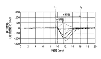
- FIG. 10 is a diagram illustrating an example of the waveforms, start timings, and end timings of a plurality of detection signals.
- the horizontal axis represents time
- the vertical axis represents the value of the detection signal (frequency change amount).
- the collection control unit 84 specifies the time t 1 the change in the detection signal is started as the start timing. Further, the collection control unit 84 specifies the time t 2 after n seconds from the start timing (time t 1 ) as the end timing.
- the collection unit 86 collects the waveform of six detecting signals definitive in from time t 1 to time t 2. In addition, the collection unit 86 collects the amount of change in each of the six detection signals from the start timing (time t 1 ) to m seconds later as the first feature amount. In addition, the collection unit 86 collects the local maximum value or the local minimum value from the start timing (time t 1 ) to after n seconds (after the second time) as the second feature amount in each of the six detection signals. To do. Further, for example, the collection unit 86 collects the time t 1 of the start timing.
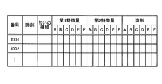
- FIG. 11 is a diagram illustrating an example of information registered in the information storage unit 36.
- the information storage unit 36 stores the odor information collected by the collection unit 86 for each generated odor.
- the information storage unit 36 stores a table as shown in FIG.
- the table stores a unique number, odor generation time, odor type, first feature value, second feature value, and waveform for each generated odor.
- the table includes the first feature amount and the second feature amount for each detection element (for example, for each of the six gas detection elements 60-A to 60-F) included in the first odor sensor 42 (second odor sensor 46). Stores features and waveforms.
- the information storage unit 36 may not store the waveform of the detection signal. Thereby, the information storage unit 36 can reduce the amount of information to be stored.
- the collection unit 86 may collect types of feature quantities other than the first feature quantity and the second feature quantity and store them in the information storage unit 36.
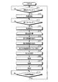
- FIG. 12 is a flowchart showing a processing flow of the information collecting unit 40.
- the information collection unit 40 executes the process of FIG.
- the information collection unit 40 determines whether the start timing has come. For example, the information collection unit 40 determines whether any one detection signal has changed more than a predetermined threshold value. If it is not the start timing (No in S11), the information collecting unit 40 waits for the process in S11. When the start timing is reached (Yes in S11), the information collection unit 40 advances the process to S12.
- the information collection unit 40 starts acquisition processing of at least one detection signal.
- the information collection unit 40 starts recording waveform data of at least one detection signal.
- the information collection unit 40 determines whether or not the end timing has come. For example, the information collection unit 40 determines whether a predetermined time has elapsed from the start timing. When it is not the end timing (No in S13), the information collecting unit 40 waits for the process in S13. When the end timing is reached (Yes in S13), the information collection unit 40 advances the process to S14.
- the information collection unit 40 ends the acquisition process of at least one detection signal.
- the information collecting unit 40 ends the recording of the waveform data of at least one detection signal.
- the information collection unit 40 executes the processing of S16 and S17 for each detection signal.
- the information collection unit 40 extracts the first feature amount from the captured detection target detection signal.
- the information collection unit 40 extracts a second feature amount from the captured detection target detection signal.
- the information collection unit 40 determines the type of the generated odor based on the acquired at least one detection signal. For example, the information collection unit 40 determines the type of odor based on the value of at least one detection signal after a certain time from the start timing (for example, after the first time (after m seconds)).
- the information collection unit 40 registers odor information in the information storage unit 36.
- the information collection unit 40 registers the time of the start timing, the odor type, the first feature value, the second feature value, and the waveform in the information storage unit 36.
- the information collecting unit 40 returns the process to S11 and repeats the process from S11.
- the sensing system 10 can monitor odors and collect odor information related to the generated odors. Thereby, according to the sensing system 10, based on the collected odor information, for example, the odor that has been determined by human senses so far can be treated as quantitative information.
- the sensing system 10 detects the amount of the odor causing substance present in the air that has not passed through the filter 44, and the detection result of the amount of the odor causing substance present in the air that has passed through the filter 44. Odor information can be collected based on the difference. Thereby, according to the sensing system 10, noise can be removed and accurate odor information can be collected.
- the sensing system 10 can monitor the odor and collect the waveform of the detection signal of the portion where the odor is generated and the feature amount of this waveform as odor information. As a result, the sensing system 10 can efficiently collect information effective for analyzing odors.
- the sensing system 10 As described above, according to the sensing system 10 according to the present embodiment, it is possible to accurately and efficiently collect information on odors.
- sensing system 10 according to a modification has substantially the same function and configuration as the sensing system 10 according to the embodiment described with reference to FIGS. 1 to 12, it is the same as a block having substantially the same function and configuration. A detailed description is omitted except for differences.
- FIG. 13 is a diagram illustrating a configuration of the sensing system 10 according to a modification.
- the sensing system 10 according to the modification further includes a heater 102 and an air introduction unit 104.
- the heater 102 heats the temperature of the air around the first odor sensor 42 and the second odor sensor 46.
- the air introduction unit 104 is a fan or a pump.
- the air introduction unit 104 ventilates the air around the first odor sensor 42 and the second odor sensor 46. That is, the air introduction unit 104 discharges the air around the first odor sensor 42 and the second odor sensor 46 to the outside, and supplies new air from the outside around the first odor sensor 42 and the second odor sensor 46. Introduce.
- the collection control unit 84 in the information collection unit 40 operates the heater 102 and the air introduction unit 104 for a certain period of time after the collection of odor information is completed. Then, the collection control unit 84 in the information collection unit 40 stops the operation of the heater 102 and the operation of the air introduction unit 104 after a certain time has elapsed, and the first odor sensor 42 and the second odor sensor 46 smell. The detection of the amount of the causative substance is started, and new odor information is collected.
- FIG. 14 is a flowchart showing a flow of processing of the information collecting unit 40 according to the modification.
- the information collection unit 40 according to the modification executes, for example, the process of FIG. First, the information collection unit 40 according to the modification executes the same processing as that described in FIG. 12 from S11 to S20.
- the information collection unit 40 advances the process to S111.
- the information collection unit 40 operates the heater 102. Thereby, the information collecting unit 40 can heat the temperature of the air around the first odor sensor 42 and the second odor sensor 46.
- the information collection unit 40 operates the air introduction unit 104. Thereby, the information collecting unit 40 can ventilate the air around the first odor sensor 42 and the second odor sensor 46.
- the information collection unit 40 determines whether or not a predetermined time has elapsed. If the predetermined time has not elapsed (No in S113), the information collecting unit 40 waits for processing in S113. When the fixed time has elapsed (Yes in S113), the information collection unit 40 returns the process to S11 and repeats the process from S11.
- the sensing system 10 according to the modified example heats the temperature of the air around the first odor sensor 42 and the second odor sensor 46 every time odor is generated and odor information is generated, and ventilation is performed. To do.
- the sensing system 10 according to the modification removes the odor-causing substance adsorbed by the first odor sensor 42 and the second odor sensor 46 and the odor-causing substance floating around the first odor sensor 42 and the second odor sensor 42, and the second odor sensor 42 and the second odor sensor 42
- the odor sensor 46 can be reset to the initial state. Therefore, the sensing system 10 according to the modification can accurately collect information on each odor even when the odor is repeatedly generated.
- the sensing system 10 according to the modification may be configured to include either the heater 102 or the air introduction unit 104.
- the sensing system 10 according to the modified example does not operate the heater 102 and the air introduction unit 104 every time an odor is generated, but, for example, the heater 102 and the air supply unit 102 every predetermined period (for example, every hour).
- the air introduction unit 104 may be operated.
- FIG. 15 is a diagram illustrating a hardware configuration of the information processing apparatus 200.
- the signal processing unit 38 and the information collecting unit 40 are realized by, for example, an information processing apparatus 200 as shown in FIG.
- the information processing apparatus 200 may have a hardware configuration similar to that of a general computer.
- the information processing device 200 includes a CPU (Central Processing Unit) 201, an operation device 202, a display device 203, a ROM (Read Only Memory) 205, a RAM (Random Access Memory) 206, a storage device 207, and a communication device. 208 and a bus 209. Each unit is connected by a bus 209.
- the CPU 201 executes various processes in cooperation with various programs stored in advance in the ROM 205 or the storage device 207 using a predetermined area of the RAM 206 as a work area, and comprehensively controls the operation of each unit constituting the information processing apparatus 200. . Further, the CPU 201 operates the operation device 202, the display device 203, the communication device 208, and the like in cooperation with a program stored in advance in the ROM 205 or the storage device 207.
- the operation device 202 is an input device such as a touch panel, a mouse, or a keyboard, and receives information input by a user as an instruction signal, and outputs the instruction signal to the CPU 201.
- the display device 203 is an LCD (Liquid Crystal Display) or the like, and displays various information based on a display signal from the CPU 201.
- the ROM 205 stores a program used for controlling the information processing apparatus 200, various setting information, and the like in a non-rewritable manner.
- the RAM 206 is a volatile storage medium such as SDRAM (Synchronous Dynamic Random Access Memory).
- SDRAM Serial Dynamic Random Access Memory
- the RAM 206 functions as a work area for the CPU 201.
- the storage device 207 is a rewritable recording device such as a semiconductor storage medium such as a flash memory or a magnetically or optically recordable storage medium.
- the storage device 207 stores a program used for controlling the information processing apparatus 200.
- the communication device 208 transmits and receives data to and from the sensor unit 30.
- the communication device 208 may transmit and receive data with a server or the like via a network.
- the program executed by the information processing apparatus 200 according to the present embodiment is stored on a computer connected to a network such as the Internet and provided by being downloaded via the network. Further, the program executed by the information processing apparatus 200 of the present embodiment may be provided by being incorporated in advance in a portable storage medium or the like.
- a program executed by the information processing apparatus 200 of the present embodiment includes a first output signal acquisition module, a second output signal acquisition module, a temperature signal acquisition module, a humidity signal acquisition module, a difference calculation module, and a correction module. And a time generation module, a collection control module, a collection module, and a determination module.
- the CPU 201 reads out such a program from a storage medium or the like, and loads each of the modules into the RAM 206 (main storage device). Then, the CPU 201 (processor) executes such a program, whereby the first output signal acquisition unit 68, the second output signal acquisition unit 70, the temperature signal acquisition unit 72, the humidity signal acquisition unit 74, and the difference calculation unit 76.
- the first output signal acquisition unit 68, the second output signal acquisition unit 70, the temperature signal acquisition unit 72, the humidity signal acquisition unit 74, the difference calculation unit 76, the correction unit 78, the time generation unit 82, the collection control unit 84, and the collection Part or all of the unit 86 and the determination unit 90 may be configured by hardware.
- the RAM 206 or the storage device 207 functions as the information storage unit 36 and the odor pattern storage unit 88.
Landscapes
- Chemical & Material Sciences (AREA)
- Health & Medical Sciences (AREA)
- Life Sciences & Earth Sciences (AREA)
- Physics & Mathematics (AREA)
- Engineering & Computer Science (AREA)
- General Physics & Mathematics (AREA)
- Immunology (AREA)
- General Health & Medical Sciences (AREA)
- Biochemistry (AREA)
- Pathology (AREA)
- Analytical Chemistry (AREA)
- Combustion & Propulsion (AREA)
- Food Science & Technology (AREA)
- Medicinal Chemistry (AREA)
- Acoustics & Sound (AREA)
- Chemical Kinetics & Catalysis (AREA)
- Investigating Or Analyzing Materials By The Use Of Fluid Adsorption Or Reactions (AREA)
- Investigating Or Analyzing Materials By The Use Of Electric Means (AREA)
Abstract
Le dispositif de l'invention collecte de manière précise et efficace des informations concernant des odeurs. Un système de détection comprend : un premier capteur d'odeur muni d'au moins un élément de détection qui détecte la quantité d'une substance émettant une odeur dans l'air; un filtre qui élimine les substances émettant des odeurs dans l'air; un second capteur d'odeur muni d'au moins un élément de détection qui détecte la quantité d'une substance émettant une odeur dans l'air et traversant le filtre; un module de calcul de différence qui génère au moins un signal de détection par calcul de la différence entre au moins un premier signal de sortie détecté par ledit au mons un élément de détection inclus dans le premier capteur d'odeur et au moins un second signal de sortie détecté par ledit au mons un élément de détection inclus dans le second capteur d'odeur; et un module de collecte qui collecte, en tant qu'informations d'odeur, des informations générées sur la base dudit au moins un signal de détection.
Priority Applications (3)
| Application Number | Priority Date | Filing Date | Title |
|---|---|---|---|
| CN201980023172.1A CN112005095A (zh) | 2018-03-29 | 2019-02-06 | 传感系统、信息处理装置、程序和信息收集方法 |
| JP2020510357A JP7235726B2 (ja) | 2018-03-29 | 2019-02-06 | センシングシステム、情報処理装置、プログラムおよび情報収集方法 |
| US17/028,040 US20210003543A1 (en) | 2018-03-29 | 2020-09-22 | Sensing system and information processing apparatus |
Applications Claiming Priority (2)
| Application Number | Priority Date | Filing Date | Title |
|---|---|---|---|
| JP2018066145 | 2018-03-29 | ||
| JP2018-066145 | 2018-03-29 |
Related Child Applications (1)
| Application Number | Title | Priority Date | Filing Date |
|---|---|---|---|
| US17/028,040 Continuation US20210003543A1 (en) | 2018-03-29 | 2020-09-22 | Sensing system and information processing apparatus |
Publications (1)
| Publication Number | Publication Date |
|---|---|
| WO2019187671A1 true WO2019187671A1 (fr) | 2019-10-03 |
Family
ID=68061131
Family Applications (1)
| Application Number | Title | Priority Date | Filing Date |
|---|---|---|---|
| PCT/JP2019/004296 Ceased WO2019187671A1 (fr) | 2018-03-29 | 2019-02-06 | Système de détection, dispositif de traitement d'informations, programme, et procédé de collecte d'informations |
Country Status (4)
| Country | Link |
|---|---|
| US (1) | US20210003543A1 (fr) |
| JP (1) | JP7235726B2 (fr) |
| CN (1) | CN112005095A (fr) |
| WO (1) | WO2019187671A1 (fr) |
Cited By (16)
| Publication number | Priority date | Publication date | Assignee | Title |
|---|---|---|---|---|
| JPWO2021186532A1 (fr) * | 2020-03-17 | 2021-09-23 | ||
| KR20230014756A (ko) * | 2020-05-29 | 2023-01-30 | 아이펙스 가부시키가이샤 | 냄새 검출 장치, 냄새 검출 방법 및 프로그램 |
| WO2023037999A1 (fr) * | 2021-09-07 | 2023-03-16 | パナソニックIpマネジメント株式会社 | Procédé d'analyse de gaz et système d'analyse de gaz |
| US11636870B2 (en) | 2020-08-20 | 2023-04-25 | Denso International America, Inc. | Smoking cessation systems and methods |
| US11760169B2 (en) | 2020-08-20 | 2023-09-19 | Denso International America, Inc. | Particulate control systems and methods for olfaction sensors |
| US11760170B2 (en) | 2020-08-20 | 2023-09-19 | Denso International America, Inc. | Olfaction sensor preservation systems and methods |
| US11813926B2 (en) | 2020-08-20 | 2023-11-14 | Denso International America, Inc. | Binding agent and olfaction sensor |
| US11828210B2 (en) | 2020-08-20 | 2023-11-28 | Denso International America, Inc. | Diagnostic systems and methods of vehicles using olfaction |
| US11881093B2 (en) | 2020-08-20 | 2024-01-23 | Denso International America, Inc. | Systems and methods for identifying smoking in vehicles |
| US11932080B2 (en) | 2020-08-20 | 2024-03-19 | Denso International America, Inc. | Diagnostic and recirculation control systems and methods |
| US12017506B2 (en) | 2020-08-20 | 2024-06-25 | Denso International America, Inc. | Passenger cabin air control systems and methods |
| US12251991B2 (en) | 2020-08-20 | 2025-03-18 | Denso International America, Inc. | Humidity control for olfaction sensors |
| US12269315B2 (en) | 2020-08-20 | 2025-04-08 | Denso International America, Inc. | Systems and methods for measuring and managing odor brought into rental vehicles |
| US12377711B2 (en) | 2020-08-20 | 2025-08-05 | Denso International America, Inc. | Vehicle feature control systems and methods based on smoking |
| WO2025204378A1 (fr) * | 2024-03-26 | 2025-10-02 | パナソニックIpマネジメント株式会社 | Système d'identification de gaz et procédé d'identification de gaz |
| JP7811801B1 (ja) * | 2024-10-16 | 2026-02-06 | 株式会社アロマビット | 出力波形の補正方法及び補正装置 |
Families Citing this family (3)
| Publication number | Priority date | Publication date | Assignee | Title |
|---|---|---|---|---|
| WO2021172592A1 (fr) * | 2020-02-28 | 2021-09-02 | 太陽誘電株式会社 | Dispositif de détection de gaz |
| JP7371981B2 (ja) * | 2020-03-23 | 2023-10-31 | 国立研究開発法人物質・材料研究機構 | 原臭選定方法、原臭の組み合わせによりニオイを表現、提示または合成する方法、及びそのための装置 |
| CN113671031B (zh) * | 2021-08-20 | 2024-06-21 | 贝壳找房(北京)科技有限公司 | 墙体空鼓检测方法和装置 |
Citations (8)
| Publication number | Priority date | Publication date | Assignee | Title |
|---|---|---|---|---|
| JPH0245445U (fr) * | 1988-09-20 | 1990-03-28 | ||
| JPH07174673A (ja) * | 1993-12-20 | 1995-07-14 | Yokogawa Electric Corp | ガス測定装置 |
| JP3912317B2 (ja) * | 2002-05-28 | 2007-05-09 | ソニー株式会社 | ガス検出装置 |
| JP2008032607A (ja) * | 2006-07-31 | 2008-02-14 | Kyushu Univ | 硫化物の悪臭を高感度で検知するセンサ |
| JP2010025562A (ja) * | 2008-07-15 | 2010-02-04 | Ngk Spark Plug Co Ltd | ガス検出装置 |
| CN101788440A (zh) * | 2010-01-15 | 2010-07-28 | 清华大学 | 一种用于食品安全监测的电子鼻 |
| US20130115137A1 (en) * | 2010-05-05 | 2013-05-09 | The Arizona Board Of Regents For And On Behlaf Of Arizona State University | Sensing materials for selective and sensitive detection of hydrocarbons and acids |
| JP5242347B2 (ja) * | 2008-11-11 | 2013-07-24 | 独立行政法人産業技術総合研究所 | 検出センサ |
Family Cites Families (10)
| Publication number | Priority date | Publication date | Assignee | Title |
|---|---|---|---|---|
| US6422061B1 (en) * | 1999-03-03 | 2002-07-23 | Cyrano Sciences, Inc. | Apparatus, systems and methods for detecting and transmitting sensory data over a computer network |
| CA2476902C (fr) * | 2003-08-20 | 2014-04-22 | Dennis S. Prince | Surveillance innovatrice du gaz par analyse spatiale et temporelle |
| CN102192970A (zh) * | 2010-03-02 | 2011-09-21 | (株)科学技术分析中心 | 臭味测定方法及臭味测定系统 |
| JP2012196357A (ja) * | 2011-03-23 | 2012-10-18 | Fujitsu General Ltd | 脱臭装置 |
| CN103913484B (zh) * | 2014-04-08 | 2016-06-08 | 广州城市职业学院 | 鱼露分类鉴别的方法 |
| CN106796207A (zh) * | 2014-08-28 | 2017-05-31 | 皇家飞利浦有限公司 | 传感器系统和感测方法 |
| JP2017067538A (ja) * | 2015-09-29 | 2017-04-06 | Toto株式会社 | 生体情報測定システム |
| JP7010446B2 (ja) * | 2016-09-27 | 2022-01-26 | 株式会社アロマビット | 匂い測定装置及び匂い測定システム |
| CN106950293A (zh) * | 2017-02-09 | 2017-07-14 | 上海应用技术大学 | 一种中药鸡汤的香气差异比较方法 |
| CN106706863A (zh) * | 2017-03-03 | 2017-05-24 | 上海赛菲环境科技股份有限公司 | 一种传感器组室内空气监测系统 |
-
2019
- 2019-02-06 WO PCT/JP2019/004296 patent/WO2019187671A1/fr not_active Ceased
- 2019-02-06 CN CN201980023172.1A patent/CN112005095A/zh active Pending
- 2019-02-06 JP JP2020510357A patent/JP7235726B2/ja active Active
-
2020
- 2020-09-22 US US17/028,040 patent/US20210003543A1/en not_active Abandoned
Patent Citations (8)
| Publication number | Priority date | Publication date | Assignee | Title |
|---|---|---|---|---|
| JPH0245445U (fr) * | 1988-09-20 | 1990-03-28 | ||
| JPH07174673A (ja) * | 1993-12-20 | 1995-07-14 | Yokogawa Electric Corp | ガス測定装置 |
| JP3912317B2 (ja) * | 2002-05-28 | 2007-05-09 | ソニー株式会社 | ガス検出装置 |
| JP2008032607A (ja) * | 2006-07-31 | 2008-02-14 | Kyushu Univ | 硫化物の悪臭を高感度で検知するセンサ |
| JP2010025562A (ja) * | 2008-07-15 | 2010-02-04 | Ngk Spark Plug Co Ltd | ガス検出装置 |
| JP5242347B2 (ja) * | 2008-11-11 | 2013-07-24 | 独立行政法人産業技術総合研究所 | 検出センサ |
| CN101788440A (zh) * | 2010-01-15 | 2010-07-28 | 清华大学 | 一种用于食品安全监测的电子鼻 |
| US20130115137A1 (en) * | 2010-05-05 | 2013-05-09 | The Arizona Board Of Regents For And On Behlaf Of Arizona State University | Sensing materials for selective and sensitive detection of hydrocarbons and acids |
Cited By (26)
| Publication number | Priority date | Publication date | Assignee | Title |
|---|---|---|---|---|
| US11846620B2 (en) | 2020-03-17 | 2023-12-19 | Nec Corporation | Noise removing apparatus, noise removing method, and recording medium |
| WO2021186532A1 (fr) * | 2020-03-17 | 2021-09-23 | 日本電気株式会社 | Dispositif d'élimination de bruit, procédé d'élimination de bruit, et support d'enregistrement |
| JP7327649B2 (ja) | 2020-03-17 | 2023-08-16 | 日本電気株式会社 | ノイズ除去装置、ノイズ除去方法、及び、プログラム |
| JPWO2021186532A1 (fr) * | 2020-03-17 | 2021-09-23 | ||
| KR20230014756A (ko) * | 2020-05-29 | 2023-01-30 | 아이펙스 가부시키가이샤 | 냄새 검출 장치, 냄새 검출 방법 및 프로그램 |
| CN115698670A (zh) * | 2020-05-29 | 2023-02-03 | 爱沛股份有限公司 | 气味检测装置、气味检测方法以及程序 |
| CN115698670B (zh) * | 2020-05-29 | 2026-01-06 | 爱沛股份有限公司 | 气味检测装置、气味检测方法以及程序 |
| KR102895813B1 (ko) | 2020-05-29 | 2025-12-03 | 아이펙스 가부시키가이샤 | 냄새 검출 장치, 냄새 검출 방법 및 프로그램 |
| US12442806B2 (en) | 2020-05-29 | 2025-10-14 | I-Pex Inc. | Odor detection device, odor detection method, and program |
| EP4462115A1 (fr) * | 2020-05-29 | 2024-11-13 | I-PEX Inc. | Dispositif de détection d'odeur, procédé de détection d'odeur et programme |
| EP4141411A4 (fr) * | 2020-05-29 | 2024-01-24 | I-PEX Inc. | Dispositif de détection d'odeurs, procédé de détection d'odeurs et programme |
| US11881093B2 (en) | 2020-08-20 | 2024-01-23 | Denso International America, Inc. | Systems and methods for identifying smoking in vehicles |
| US12269315B2 (en) | 2020-08-20 | 2025-04-08 | Denso International America, Inc. | Systems and methods for measuring and managing odor brought into rental vehicles |
| US11813926B2 (en) | 2020-08-20 | 2023-11-14 | Denso International America, Inc. | Binding agent and olfaction sensor |
| US11932080B2 (en) | 2020-08-20 | 2024-03-19 | Denso International America, Inc. | Diagnostic and recirculation control systems and methods |
| US12017506B2 (en) | 2020-08-20 | 2024-06-25 | Denso International America, Inc. | Passenger cabin air control systems and methods |
| US11760170B2 (en) | 2020-08-20 | 2023-09-19 | Denso International America, Inc. | Olfaction sensor preservation systems and methods |
| US12251991B2 (en) | 2020-08-20 | 2025-03-18 | Denso International America, Inc. | Humidity control for olfaction sensors |
| US11828210B2 (en) | 2020-08-20 | 2023-11-28 | Denso International America, Inc. | Diagnostic systems and methods of vehicles using olfaction |
| US12377711B2 (en) | 2020-08-20 | 2025-08-05 | Denso International America, Inc. | Vehicle feature control systems and methods based on smoking |
| US11636870B2 (en) | 2020-08-20 | 2023-04-25 | Denso International America, Inc. | Smoking cessation systems and methods |
| US11760169B2 (en) | 2020-08-20 | 2023-09-19 | Denso International America, Inc. | Particulate control systems and methods for olfaction sensors |
| WO2023037999A1 (fr) * | 2021-09-07 | 2023-03-16 | パナソニックIpマネジメント株式会社 | Procédé d'analyse de gaz et système d'analyse de gaz |
| WO2025204378A1 (fr) * | 2024-03-26 | 2025-10-02 | パナソニックIpマネジメント株式会社 | Système d'identification de gaz et procédé d'identification de gaz |
| JP7811801B1 (ja) * | 2024-10-16 | 2026-02-06 | 株式会社アロマビット | 出力波形の補正方法及び補正装置 |
| WO2026083895A1 (fr) * | 2024-10-16 | 2026-04-23 | 株式会社アロマビット | Procédé de correction de forme d'onde de sortie et dispositif de correction associé |
Also Published As
| Publication number | Publication date |
|---|---|
| JP7235726B2 (ja) | 2023-03-08 |
| CN112005095A (zh) | 2020-11-27 |
| US20210003543A1 (en) | 2021-01-07 |
| JPWO2019187671A1 (ja) | 2021-03-18 |
Similar Documents
| Publication | Publication Date | Title |
|---|---|---|
| JP7235726B2 (ja) | センシングシステム、情報処理装置、プログラムおよび情報収集方法 | |
| US11644449B2 (en) | Sensing system, information processing apparatus, and sensor apparatus | |
| JP7442102B2 (ja) | 測定端末、測定システム、測定方法およびプログラム | |
| KR101317986B1 (ko) | 진동 이벤트 분석 방법 및 회전 기계 모니터링 시스템 | |
| WO2019187672A1 (fr) | Dispositif de cuisson, dispositif de traitement d'informations, programme, procédé de commande | |
| WO2019123865A1 (fr) | Système de détection, programme associé, dispositif et procédé de traitement de l'information | |
| JP7658984B2 (ja) | 匂い測定装置、制御装置及び匂い判定方法 | |
| JP6842126B2 (ja) | 振動解析システム、振動解析方法及びプログラム | |
| CN114780402B (zh) | 一种芯片仿真系统的调试方法、装置及服务器 | |
| JP7327649B2 (ja) | ノイズ除去装置、ノイズ除去方法、及び、プログラム | |
| EP3761843A1 (fr) | Procédé de réglage du moment de libération d'un agent de nettoyage pendant un cycle de nettoyage dans un appareil électroménager | |
| KR102585704B1 (ko) | 터치스크린의 햅틱 진동을 모니터링하는 방법 및 장치 | |
| CN101592520A (zh) | 光强度侦测方法与装置、显示装置及存储媒体 | |
| JP5168544B2 (ja) | プラント運転支援装置 | |
| US20220413926A1 (en) | Model management system and model management method | |
| KR100876158B1 (ko) | 압전 센서를 이용한 생체물질 검출 장치 및 검출 방법 | |
| JP7312884B2 (ja) | センシングシステムおよび情報処理装置 | |
| US11598693B2 (en) | Information processing apparatus, information processing method, and non-transitory computer readable medium | |
| TW202328658A (zh) | 物質檢測系統 | |
| JPH1164258A (ja) | 熱分析装置 | |
| JP2024146356A (ja) | 情報処理装置および測定システム | |
| Walter et al. | Improving the accuracy of expression data analysis in time course experiments using resampling | |
| RU2566611C2 (ru) | Способ вибродиагностики печатных узлов | |
| JP7585640B2 (ja) | 信号処理方法及び信号処理装置 | |
| ATE343779T1 (de) | Verfahren und vorrichtung zur bearbeitung von schwingungsdaten |
Legal Events
| Date | Code | Title | Description |
|---|---|---|---|
| 121 | Ep: the epo has been informed by wipo that ep was designated in this application |
Ref document number: 19778104 Country of ref document: EP Kind code of ref document: A1 |
|
| ENP | Entry into the national phase |
Ref document number: 2020510357 Country of ref document: JP Kind code of ref document: A |
|
| NENP | Non-entry into the national phase |
Ref country code: DE |
|
| 122 | Ep: pct application non-entry in european phase |
Ref document number: 19778104 Country of ref document: EP Kind code of ref document: A1 |