WO2019187964A1 - Tête d'étanchéification pour la fabrication d'une unité à plaques de verre et procédé pour l'étanchéification d'un article en cours de traitement d'une unité à plaques de verre - Google Patents
Tête d'étanchéification pour la fabrication d'une unité à plaques de verre et procédé pour l'étanchéification d'un article en cours de traitement d'une unité à plaques de verre Download PDFInfo
- Publication number
- WO2019187964A1 WO2019187964A1 PCT/JP2019/007921 JP2019007921W WO2019187964A1 WO 2019187964 A1 WO2019187964 A1 WO 2019187964A1 JP 2019007921 W JP2019007921 W JP 2019007921W WO 2019187964 A1 WO2019187964 A1 WO 2019187964A1
- Authority
- WO
- WIPO (PCT)
- Prior art keywords
- frame
- substrate
- glass panel
- sealing head
- panel unit
- Prior art date
- Legal status (The legal status is an assumption and is not a legal conclusion. Google has not performed a legal analysis and makes no representation as to the accuracy of the status listed.)
- Ceased
Links
Images

Classifications
-
- C—CHEMISTRY; METALLURGY
- C03—GLASS; MINERAL OR SLAG WOOL
- C03C—CHEMICAL COMPOSITION OF GLASSES, GLAZES OR VITREOUS ENAMELS; SURFACE TREATMENT OF GLASS; SURFACE TREATMENT OF FIBRES OR FILAMENTS MADE FROM GLASS, MINERALS OR SLAGS; JOINING GLASS TO GLASS OR OTHER MATERIALS
- C03C27/00—Joining pieces of glass to pieces of other inorganic material; Joining glass to glass other than by fusing
- C03C27/06—Joining glass to glass by processes other than fusing
- C03C27/10—Joining glass to glass by processes other than fusing with the aid of adhesive specially adapted for that purpose
-
- C—CHEMISTRY; METALLURGY
- C03—GLASS; MINERAL OR SLAG WOOL
- C03C—CHEMICAL COMPOSITION OF GLASSES, GLAZES OR VITREOUS ENAMELS; SURFACE TREATMENT OF GLASS; SURFACE TREATMENT OF FIBRES OR FILAMENTS MADE FROM GLASS, MINERALS OR SLAGS; JOINING GLASS TO GLASS OR OTHER MATERIALS
- C03C27/00—Joining pieces of glass to pieces of other inorganic material; Joining glass to glass other than by fusing
- C03C27/06—Joining glass to glass by processes other than fusing
-
- E—FIXED CONSTRUCTIONS
- E06—DOORS, WINDOWS, SHUTTERS, OR ROLLER BLINDS IN GENERAL; LADDERS
- E06B—FIXED OR MOVABLE CLOSURES FOR OPENINGS IN BUILDINGS, VEHICLES, FENCES OR LIKE ENCLOSURES IN GENERAL, e.g. DOORS, WINDOWS, BLINDS, GATES
- E06B3/00—Window sashes, door leaves, or like elements for closing wall or like openings; Layout of fixed or moving closures, e.g. windows in wall or like openings; Features of rigidly-mounted outer frames relating to the mounting of wing frames
- E06B3/66—Units comprising two or more parallel glass or like panes permanently secured together
- E06B3/6612—Evacuated glazing units
-
- E—FIXED CONSTRUCTIONS
- E06—DOORS, WINDOWS, SHUTTERS, OR ROLLER BLINDS IN GENERAL; LADDERS
- E06B—FIXED OR MOVABLE CLOSURES FOR OPENINGS IN BUILDINGS, VEHICLES, FENCES OR LIKE ENCLOSURES IN GENERAL, e.g. DOORS, WINDOWS, BLINDS, GATES
- E06B3/00—Window sashes, door leaves, or like elements for closing wall or like openings; Layout of fixed or moving closures, e.g. windows in wall or like openings; Features of rigidly-mounted outer frames relating to the mounting of wing frames
- E06B3/66—Units comprising two or more parallel glass or like panes permanently secured together
- E06B3/677—Evacuating or filling the gap between the panes ; Equilibration of inside and outside pressure; Preventing condensation in the gap between the panes; Cleaning the gap between the panes
- E06B3/6775—Evacuating or filling the gap during assembly
-
- E—FIXED CONSTRUCTIONS
- E06—DOORS, WINDOWS, SHUTTERS, OR ROLLER BLINDS IN GENERAL; LADDERS
- E06B—FIXED OR MOVABLE CLOSURES FOR OPENINGS IN BUILDINGS, VEHICLES, FENCES OR LIKE ENCLOSURES IN GENERAL, e.g. DOORS, WINDOWS, BLINDS, GATES
- E06B3/00—Window sashes, door leaves, or like elements for closing wall or like openings; Layout of fixed or moving closures, e.g. windows in wall or like openings; Features of rigidly-mounted outer frames relating to the mounting of wing frames
- E06B3/66—Units comprising two or more parallel glass or like panes permanently secured together
- E06B3/673—Assembling the units
- E06B3/67339—Working the edges of already assembled units
- E06B3/6736—Heat treatment
-
- Y—GENERAL TAGGING OF NEW TECHNOLOGICAL DEVELOPMENTS; GENERAL TAGGING OF CROSS-SECTIONAL TECHNOLOGIES SPANNING OVER SEVERAL SECTIONS OF THE IPC; TECHNICAL SUBJECTS COVERED BY FORMER USPC CROSS-REFERENCE ART COLLECTIONS [XRACs] AND DIGESTS
- Y02—TECHNOLOGIES OR APPLICATIONS FOR MITIGATION OR ADAPTATION AGAINST CLIMATE CHANGE
- Y02A—TECHNOLOGIES FOR ADAPTATION TO CLIMATE CHANGE
- Y02A30/00—Adapting or protecting infrastructure or their operation
- Y02A30/24—Structural elements or technologies for improving thermal insulation
- Y02A30/249—Glazing, e.g. vacuum glazing
-
- Y—GENERAL TAGGING OF NEW TECHNOLOGICAL DEVELOPMENTS; GENERAL TAGGING OF CROSS-SECTIONAL TECHNOLOGIES SPANNING OVER SEVERAL SECTIONS OF THE IPC; TECHNICAL SUBJECTS COVERED BY FORMER USPC CROSS-REFERENCE ART COLLECTIONS [XRACs] AND DIGESTS
- Y02—TECHNOLOGIES OR APPLICATIONS FOR MITIGATION OR ADAPTATION AGAINST CLIMATE CHANGE
- Y02B—CLIMATE CHANGE MITIGATION TECHNOLOGIES RELATED TO BUILDINGS, e.g. HOUSING, HOUSE APPLIANCES OR RELATED END-USER APPLICATIONS
- Y02B80/00—Architectural or constructional elements improving the thermal performance of buildings
- Y02B80/22—Glazing, e.g. vaccum glazing
Definitions
- the present disclosure relates to a sealing head for manufacturing a glass panel unit and a method for sealing a work in progress of the glass panel unit.
- a heat-insulating glass panel unit can be manufactured by reducing the internal space between a pair of substrates positioned facing each other and sealing the internal space in a reduced pressure state.
- Patent Document 1 discloses a technique in which a glass exhaust pipe is connected to an exhaust hole of one of a pair of substrates, and the internal space is decompressed through the exhaust pipe, and then the exhaust pipe is heated and cut. Are listed.
- the trace of the cut exhaust pipe remains on the glass panel unit formed by this technique in a state of protruding from the outer surface of the glass panel unit.
- This disclosure is intended to manufacture a glass panel unit having a decompressed internal space by a technique that does not leave a trace of an exhaust pipe.
- a sealing head for manufacturing a glass panel unit includes a frame that is detachably attached to a work in progress of the glass panel unit, an air intake portion that is supported by the frame, and a frame that is supported by the frame.
- the work-in-process includes a first substrate including a glass panel and an exhaust hole formed therein, a second substrate including the glass panel, and the first substrate and the second substrate positioned opposite to each other in an airtight manner.
- the intake portion is configured to suck air in the internal space through the exhaust hole, and the pressing pin is formed of a hot-melt sealing material inserted into the exhaust hole to seal the exhaust hole.
- the non-contact heater is configured to locally heat the sealing material through the second substrate in a non-contact manner, the suction portion, the pressing pin, and the second substrate.
- the non-contact heater is detachably attached to the work in progress integrally with the frame.
- a method for sealing a work in progress of a glass panel unit uses the sealing head, and the internal space is configured by detachably mounting the sealing head on a corner portion of the work in progress. And the exhaust hole is sealed.
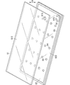
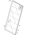
- FIG. 1 is a perspective view explaining the arrangement process for manufacturing the glass panel unit of one embodiment.
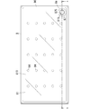
- FIG. 2 is a plan view for explaining an arrangement process and a bonding process for manufacturing the glass panel unit.
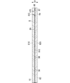
- 3 is a schematic cross-sectional view taken along line AA in FIG.
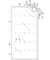
- FIG. 4 is a plan view for explaining a decompression step for manufacturing the glass panel unit same as above.
- FIG. 5 is a schematic sectional view taken along line BB in FIG.
- FIG. 6 is a schematic cross-sectional view taken along the line CC of FIG.
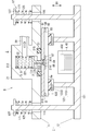
- FIG. 7: is a schematic sectional drawing explaining the sealing process for manufacturing the glass panel unit same as the above.
- FIG. 8 is a perspective view of a glass panel unit manufactured through the same sealing process.
- FIG. 8 is a perspective view of a glass panel unit manufactured through the same sealing process.
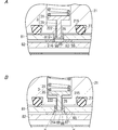
- FIG. 9A is a cross-sectional view of a main part for explaining a pressure reduction process using the first modification of the sealing head described above
- FIG. 9B illustrates a sealing process using the first modification of the sealing head described above. It is principal part sectional drawing.
- FIG. 10 is a schematic cross-sectional view for explaining a pressure reduction process using the second modification of the sealing head.
- a method for manufacturing a glass panel unit includes an arrangement process, a bonding process, a decompression process, and a sealing process.
- the work-in-process 8 is formed through the placement process and the joining process.
- the work-in-progress 8 is an article in the middle of manufacturing the glass panel unit.
- a heat-insulating glass panel unit is formed by performing a decompression process and a sealing process on the work-in-process 8 using a sealing head 9 for manufacturing a glass panel unit.
- the first substrate 81, the second substrate 82, the bonding material 83, the plurality of pillars 84, and the dam portion 87 are arranged at predetermined positions, respectively.
- the bonding material 83, the weir portion 87, and the plurality of pillars 84 are disposed on one surface (that is, the upper surface) of the second substrate 82.
- a first substrate 81 is disposed above the second substrate 82 so as to face it.
- the first substrate 81 includes a glass panel 810 having translucency.
- the second substrate 82 includes a glass panel 820 having translucency.
- the glass panel 810 included in the first substrate 81 is referred to as a first glass panel 810
- the glass panel 820 included in the second substrate 82 is referred to as a second glass panel 820.
- a low radiation film 812 is overlaid on one surface (lower surface) of the first glass panel 810 (see FIG. 3). Most of the surface of the first substrate 81 facing the second substrate 82 is constituted by the surface of the low radiation film 812. The surface of the second substrate 82 that faces the first substrate 81 is constituted by the surface of the second glass panel 820.
- An exhaust hole 815 is formed through the first substrate 81.
- the exhaust hole 815 penetrates the first glass panel 810 in the thickness direction D1.
- the low radiation film 812 is not overlapped so as to cover the entire surface of the first glass panel 810, and the peripheral edge of the entire surface of the first glass panel 810 and the exhaust hole in the surface of the first glass panel 810. A peripheral portion of 815 is not covered with the low emission film 812.
- the bonding material 83 is disposed on the second substrate 82 (that is, the second glass panel 820) using a coating device such as a dispenser. As shown in FIG. 1, the bonding material 83 is arranged in a frame shape along the outer peripheral edge of one surface (that is, the upper surface) of the second substrate 82.
- the dam portion 87 is disposed on the second substrate 82 (that is, the second glass panel 820) using a coating device such as a dispenser.
- the dam portion 87 is arranged at a predetermined position on one surface of the second substrate 82 so as to have an annular shape having a notch 875.
- the material of the bonding material 83 and the material of the weir portion 87 are preferably the same material (for example, glass frit).
- the dam portion 87 has a C-shape having a notch 875, but the shape of the dam portion 87 is not limited to this.
- the plurality of pillars 84 are regularly distributed in a region surrounded by the bonding material 83 on one surface of the second substrate 82.
- the dimension shape, number and arrangement of the plurality of pillars 84 are not particularly limited.
- the first substrate 81 and the second substrate 82 that are opposed to each other in the arrangement step are bonded in an airtight manner via the bonding material 83.
- the first substrate 81 and the second substrate 82 arranged to face each other with the joining material 83, the weir portion 87, and the plurality of pillars 84 sandwiched therebetween are placed in a joining furnace such as a hot air circulating furnace. It is heated and the bonding material 83 is once melted and then cured. As a result, the bonding material 83 becomes a frame-shaped bonding portion 86 that bonds the peripheral portions of the first substrate 81 and the second substrate 82 in an airtight manner.
- an internal space 85 is formed between the first substrate 81 and the second substrate 82 (see FIG. 3 and the like).
- the internal space 85 is a space surrounded by the first substrate 81, the second substrate 82, and the joint portion 86, and communicates with the external space only through the exhaust hole 815.
- the work-in-progress 8 is formed through the above arrangement process and joining process.
- the exhaust hole 815 of the first substrate 81 is located surrounded by the dam portion 87 (see FIG. 2).
- the thickness direction D1 is the thickness direction of the first substrate 81, the thickness direction of the second substrate 82, and the overall thickness direction of the work-in-progress 8.
- the first substrate 81 including the first glass panel 810 and the exhaust hole 815 formed, and the second substrate 82 including the second glass panel 820 are connected via the frame-shaped joint portion 86. Airtightly joined.
- An internal space 85 is formed between the first substrate 81 and the second substrate 82 so as to be surrounded by the joint 86.
- a weir portion 87 having a notch 875 is disposed in the internal space 85 so as to surround the opening of the exhaust hole 815.
- the work-in-process 8 has a rectangular outer shape when viewed from the thickness direction D1.
- the first substrate 81 and the second substrate 82 have a rectangular outer shape.
- the exhaust hole 815 and the weir part 87 are located in the corner part 8a when the work-in-process 8 is viewed from the thickness direction D1.
- the dam portion 87 is bonded to the first substrate 81 by being cured once heated and melted in the bonding step, but the dam portion 87 may be bonded to the second substrate 82.
- the notches 875 are formed only at one location of the dam portion 87, but may be formed at a plurality of locations spaced in the circumferential direction of the dam portion 87.
- the notch 875 is formed so as to divide the dam portion 87, but is not limited thereto.
- a part of the weir part 87 in the circumferential direction may be formed one step lower than the remaining part, and this part (that is, a part recessed from the remaining part) may be a notch.
- the heat-insulating glass panel unit can be manufactured by performing an operation for sealing the exhaust hole 815 while maintaining the internal space 85 in a reduced pressure state for the work-in-process 8. That is, a heat-insulating glass panel unit can be manufactured by further performing a decompression process and a sealing process on the work-in-process 8.
- the decompression step and the sealing step are performed in this order using the sealing head 9 shown in FIGS.
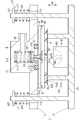
- the sealing head 9 is detachably attached to a right-angled corner portion 8a of the work-in-process 8.
- the structure of the sealing head 9 will be described below.
- the sealing head 9 includes a decompression mechanism capable of decompressing the internal space 85 of the work-in-progress 8, a sealing mechanism capable of sealing the internal space 85 in a decompressed state,
- the frame 1 that supports these mechanisms is integrally provided.
- the decompression mechanism is a mechanism including an air intake unit 2 described later.
- the sealing mechanism is a mechanism including a pressing pin 3 and a non-contact heater 4 which will be described later.
- the intake portion 2, the pressing pin 3, and the non-contact heater 4 are detachably attached to the corner portion 8a.
- the frame 1 includes a first frame 11 pressed against the corner portion of the first substrate 81 from above and a second frame 12 pressed against the corner portion of the second substrate 82 from below.
- the first frame 11 integrally supports a cylindrical intake portion 2 having an intake passage 22 therein.
- the intake portion 2 has a function of sucking air in the internal space 85 through the exhaust hole 815 of the work-in-progress 8.
- the intake section 2 is configured to depressurize the internal space 85 through the exhaust hole 815 and maintain the internal space 85 in a depressurized state.
- the air intake section 2 includes a bottomed cylindrical hollow body 21 having a bottom 212 on the upper side and an opening 214 on the lower side, and a pipe-shaped connection section 28 extending laterally from the hollow body 21.
- the internal space of the hollow body 21 constitutes the intake passage 22.
- the hollow body 21 only needs to have the intake passage 22 and the opening 214, and the shape thereof is not particularly limited.
- the internal flow path of the connection part 28 is connected to an intake device (not shown).
- the intake passage 22 has a series of a first intake passage 221 located on the upper side (that is, the side closer to the bottom 212) and a second intake passage 222 located on the lower side (that is, the side closer to the opening 214).
- the first intake path 221 communicates with the internal flow path of the connection portion 28.
- the second intake path 222 communicates with the opening 214 of the hollow body 21.
- the second intake path 222 has a smaller cross-sectional area than the first intake path 221, and a step is formed at the boundary between the first intake path 221 and the second intake path 222.
- the pressing pin 3 is movably disposed in the intake passage 22.
- the pressing pin 3 integrally includes a plate-like base portion 31 and a columnar pin body 35 protruding downward from a part of the base portion 31.
- the base 31 is located in the first intake passage 221.
- a part of the pin body 35 is located in the second intake passage 222.
- the pressing pin 3 is guided by the inner peripheral surface 2220 of the second intake passage 222 and is movable up and down (that is, in a direction approaching and separating from the second substrate 82).
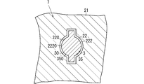
- the rotation of the pressing pin 3 with respect to the first frame 11 is regulated by a rotation preventing structure 7 shown in FIG.
- the anti-rotation structure 7 is formed by the outer peripheral surface 30 of the pressing pin 3 and the inner peripheral surface 220 of the intake passage 22.
- the outer peripheral surface 30 of the pressing pin 3 that constitutes a part of the detent structure 7 is an outer peripheral surface 350 having a non-circular cross section of the pin body 35.
- An inner peripheral surface 220 of the intake passage 22 constituting another part of the rotation stopper structure 7 is an inner peripheral surface 2220 having a non-circular cross section of the second intake passage 222.
- a plurality (two in this embodiment) of protrusions are provided on the outer peripheral surface 350 of the pin body 35, and the plurality of protrusions are provided on the inner peripheral surface 2220 of the second intake passage 222.
- Plural (two in this embodiment) grooves are provided in which the strips can be moved up and down.
- the shapes of the pin main body 35 and the second intake passage 222 are not limited to this, and other shapes may be used as long as they fit in such a manner that they cannot be relatively rotated.
- a compressed spring member 51 is further accommodated in the first intake passage 221 shown in FIG.
- the spring member 51 presses against the bottom 212 of the hollow body 21 and presses against the base 31 of the pressing pin 3, thereby constantly applying a downward biasing force to the base 31.
- the pin body 35 is pushed downward (that is, in a direction approaching the second substrate 82) through the opening 214 of the hollow body 21 by the biasing force applied to the base 31 by the spring member 51.
- the spring member 51 is supported by the first frame 11. In the sealing head 9 of the present embodiment, the spring member 51 forms the pin spring mechanism 5 that pushes the pressing pin 3 toward the second substrate 82.
- An annular groove 215 is formed in a portion surrounding the opening 214 on the lower surface of the hollow body 21.
- An O-ring 27 having elasticity is arranged in the groove 215. With the O-ring 27 partially fitted in the groove 215, the remaining portion protrudes downward.
- the second frame 12 includes a base 121 that supports the non-contact heater 4 from below, a pressing portion 123 that presses against the second substrate 82 from below, and a plurality of connecting rods 125 that protrude upward from the base 121. Have one.
- the non-contact heater 4 is an electromagnetic wave irradiator 40 configured to irradiate an electromagnetic wave for local heating.
- the electromagnetic wave irradiated by the electromagnetic wave irradiator 40 is infrared.
- the electromagnetic wave irradiator 40 irradiates infrared rays through the second substrate 82 (that is, the second glass panel 820) having translucency with respect to the heat-meltable sealing material 89 inserted into the exhaust hole 815 as will be described later.
- the sealing material 89 is configured to be heated locally.
- the electromagnetic wave irradiator 40 includes a heat source unit 401 that can emit infrared rays, and a condensing unit 402 that collects infrared rays emitted from the heat source unit 401 at a target location.
- the heat source unit 401 is preferably a halogen lamp that emits near infrared rays. If the infrared ray irradiated from the electromagnetic wave irradiator 40 is a near infrared ray having a short wavelength, there is an advantage that the near infrared ray is hardly absorbed when passing through the second substrate 82.
- the sealing material 89 When irradiating near-infrared rays from the electromagnetic wave irradiator 40, the sealing material 89 may be formed using a black material having a high near-infrared absorptivity so that the near-infrared absorptivity of the sealing material 89 is 30% or more. preferable.
- the pressing part 123 is in a position surrounding the electromagnetic wave irradiator 40 when the second frame 12 is viewed from the thickness direction D1.
- the pressing portion 123 includes a column 1231 that protrudes upward from the base 121, and a contact portion 1233 that is supported above the base 121 by the column 1231.
- the contact portion 1233 is a portion that hits the second substrate 82 from below, and preferably has elasticity.
- the second frame 12 supports the shielding plate 6.
- the shielding plate 6 is a plate material that can block electromagnetic waves, that is, infrared rays, and a through hole 60 that allows infrared rays to pass toward the sealing material 89 is provided in the central portion thereof.
- the shielding plate 6 is a plate material for passing the portion irradiated toward the sealing material 89 and blocking at least a part of the remaining portion of the infrared rays irradiated by the electromagnetic wave irradiator 40.
- the shielding plate 6 is shielded by the shielding plate 6, so that the deterioration of the O-ring 27 may proceed due to the influence of infrared rays. It can be suppressed.
- the plurality of rods 125 included in the second frame 12 are inserted into the plurality of connecting holes 115 formed in the first frame 11 on a one-to-one basis. Thereby, the first frame 11 and the second frame 12 are connected so as to be relatively displaceable in the direction in which the first substrate 81 and the second substrate 82 face each other (that is, the thickness direction D1).
- the plurality of connecting holes 115 are located at positions surrounding the hollow body 21 when the first frame 11 is viewed from the thickness direction D1.
- a retaining portion 127 is provided at the tip of each of the plurality of rods 125.
- the retaining portion 127 has a larger diameter than the connection hole 115.
- the retaining portion 127 is located above the first frame 11.
- a compressed spring member 171 is interposed between the retaining portion 127 and the first frame 11.
- the plurality of spring members 171 assembled to the plurality of rods 125 give a biasing force that biases the first frame 11 and the second frame 12 toward each other.
- the plurality of spring members 171 form a frame spring mechanism 17 that urges the first frame 11 and the second frame 12 toward each other.
- the work-in-process 8 When mounting the sealing head 9, the work-in-process 8 is set so that the first substrate 81 is positioned above the second substrate 82.
- the intake portion 2 supported by the first frame 11 is set so as to be positioned above the exhaust hole 815 with the opening 214 facing downward.
- the pressing pin 3 is located above the exhaust hole 815.
- a sealing material 89 and a plate 88 are inserted in advance into the exhaust hole 815 of the work-in-process 8.
- the sealing material 89 is a solid sealing material formed using, for example, glass frit.
- the plate 88 is a disk-shaped plate formed using, for example, metal.
- Both the sealing material 89 and the plate 88 have an outer diameter smaller than that of the exhaust hole 815.
- the plate 88 has an outer diameter larger than that of the sealing material 89.
- the plate 88 disposed in the exhaust hole 815 is located on the opposite side of the second substrate 82 with the sealing material 89 interposed therebetween.
- the exhaust hole 815 of the first substrate 81 and the intake passage 22 of the hollow body 21 communicate with each other in an airtight manner.
- the pin spring mechanism 5 functions as a holding mechanism that holds the sealing material 89 in the exhaust hole 815.
- the depressurization step when air is sucked through the connection portion 28 in this state (see the white arrow in FIG. 5), the internal space 85 is depressurized until the degree of vacuum is, for example, 0.1 Pa or less.
- a sealing material 89 and a plate 88 are inserted into the exhaust hole 815, but there is a gap between the inner peripheral surface of the exhaust hole 815 and the sealing material 89, and there is a gap between the exhaust hole 815 and the plate 88. There is a gap between the two gaps. Accordingly, the air in the internal space 85 is smoothly sucked through the exhaust holes 815 of the first substrate 81 and the notches 875 in the dam portions 87 disposed in the internal space 85.
- the non-contact heater 4 supported by the second frame 12 seals the internal space 85 with the pressure reduced.
- the non-contact heater 4 is configured to heat the sealing material 89 inserted into the exhaust hole 815 locally and in a non-contact manner while the internal space 85 remains in a decompressed state.
- the locally heated sealing material 89 melts and softens when it reaches a predetermined temperature.
- the softened sealing material 89 is pushed and deformed toward the second substrate 82 by the urging force (spring force) exerted by the spring member 51 via the plate 88.
- the sealing material 89 is expanded in a direction orthogonal to the thickness direction D1 and is deformed until it hits the inner peripheral surface of the weir portion 87 in the internal space 85. When the sealing material 89 hits the weir portion 87, further expansion is suppressed.
- the notch 875 of the weir part 87 is sealed by a sealing material 89 that is expanded until it hits the weir part 87.
- the exhaust hole 815 is sealed with the sealing material 89, and the internal space 85 is hermetically sealed in a reduced pressure state.
- the sealing material 89 is bonded to both the first substrate 81 and the second substrate 82 in the internal space 85.
- the trace of the exhaust pipe as described in the prior art does not remain. Therefore, the trace of the exhaust pipe does not cause damage to the glass panel unit.
- the plate 88 remains in the exhaust hole 815, but the plate 88 is sealed after the exhaust hole 815 is sealed. It is also possible to remove.
- the intake portion 2, the pressing pin 3, and the non-contact heater 4 are all attached to the corner portion 8a of the work in process 8 where the exhaust holes 815 are formed. And can be detachably attached integrally. Therefore, the internal space 85 of the work-in-process 8 can be depressurized and sealed in a depressurized state with a simple operation of attaching and detaching the frame 1 to and from the corner portion 8a. It does not remain.
- the frame 1 places the pressing pin 3 and the non-contact heater 4 at positions opposite to each other across the second substrate 82 of the work in process 8.
- the non-contact heater 4 locally heats the sealing material 89 through the second substrate 82 in a non-contact manner. Therefore, the sealing material 89 can be heated and melted by infrared rays irradiated from the opposite side to the pressing pin 3 while applying a load to the sealing material 89 with the pressing pin 3, and the sealing work of the internal space 85 is efficiently performed. Can be done.
- the first frame 11 that supports the intake portion 2 and the pressing pin 3 and the second frame 12 that supports the non-contact heater 4 are mutually connected by the frame spring mechanism 17. It is energized in the approaching direction. Therefore, the frame 1 including the first frame 11 and the second frame 12 can be easily set in a form in which the work-in-process 8 is sandwiched from both sides in the thickness direction D1. Moreover, when the dimension of the work-in-process 8 in the thickness direction D1 changes due to the decompression of the internal space 85, the distance between the first frame 11 and the second frame 12 naturally changes accordingly.
- the hollow body 21 further has a protruding portion 25 inserted into the exhaust hole 815.
- the protruding portion 25 is an annular protrusion formed so as to surround the opening 214 on the lower surface of the hollow body 21.
- An air-permeable space is formed between the annular protruding portion 25 and the columnar pin body 35.
- the protruding portion 25 is formed continuously in the circumferential direction, but may be formed intermittently.
- the projecting portion 25 inserted into the exhaust hole 815 functions to suppress the wraparound of the seal material 89. To do. Therefore, in the first modification, the heat-melted sealing material 89 is suppressed from adhering to the pressing pin 3.
- the operator grasps the first frame 11 and focuses on the axis of the pressing pin 3.
- the first frame 11 may be rotated. Since the relative rotation between the pressing pin 3 and the first frame 11 is restricted by the detent structure 7 shown in FIG. 6, when the first frame 11 is rotated, the pressing pin 3 rotates integrally with the first frame 11. To do. As a result, the portion of the sealing material 89 attached to the pressing pin 3 is peeled off from the pressing pin 3.
- FIG. 10 shows a second modification of the sealing head 9.
- the non-contact heater 4 supported by the base 121 of the second frame 12 is a magnetic field generator 45 including a coil 450 that generates a magnetic field for induction heating.
- the work-in-process 8 can be decompressed and sealed without the trace of the exhaust pipe remaining as in the prior art.
- infrared rays are emitted from the electromagnetic wave irradiator 40.
- the sealing material 89 can be locally heated through the second substrate 82, it is possible to irradiate electromagnetic waves of a different type from infrared rays. is there.
- the shielding board 6 should just have the property which can interrupt
- the pressing pin 3 is pressed against the sealing material 89 via the plate 88, but the plate 88 is not essential, and the pressing pin 3 can also be pressed directly against the sealing material 89.
- the dam portion 87 is provided in the internal space 85 of the work-in-process 8, but the dam portion 87 is not essential. It is also possible to seal the exhaust hole 815 by crushing the sealing material 89 with the pressing pin 3 without providing the dam portion 87 in the internal space 85.
- the exhaust holes 815 are provided in one corner portion among the four corner portions of the first substrate 81 of the work-in-progress 8, but the exhaust holes 815 are provided in a plurality of corner portions. It may be provided.
- the internal space 85 can be depressurized and sealed by using a plurality of sealing heads 9 and mounting the sealing heads 9 at the corners at each location.
- the internal space 85 is depressurized until the degree of vacuum is 0.1 Pa or less, but the degree of depressurization of the internal space 85 is not limited to this.
- the sealing head (9) of the first aspect includes a frame (1), an intake portion (2), a pressing pin (3), and a non-contact heater. (4) is provided.
- the frame (1) is detachably attached to the work piece (8) of the glass panel unit.
- the intake part (2), the pressing pin (3), and the non-contact heater (4) are supported by the frame (1).
- the work-in-process (8) has a first substrate (81), a second substrate (82), a joint (86), and an internal space (85).
- the first substrate (81) includes a glass panel (810) and an exhaust hole (815) is formed.
- the second substrate (82) includes a glass panel (820).
- the joining portion (86) joins the first substrate (81) and the second substrate (82) that face each other in an airtight manner.
- the internal space (85) is formed surrounded by the first substrate (81), the second substrate (82), and the joint (86), and communicates with the exhaust hole (815).
- the intake part (2) is configured to suck air in the internal space (85) through the exhaust hole (815).
- the pressing pin (3) pushes the hot-melt sealing material (89) inserted into the exhaust hole (815) toward the second substrate (82) to seal the exhaust hole (815). It is configured.
- the non-contact heater (4) is configured to locally heat the sealing material (89) through the second substrate (82) in a non-contact manner.
- the air intake (2), the pressing pin (3), and the non-contact heater (4) are detachably attached to the work in process (8) integrally with the frame (1).
- the sealing head (9) of the first aspect the internal space (85) of the work-in-process (8) is decompressed and the exhaust hole (815) is sealed using the sealing head (9).
- the exhaust pipe trace as in the prior art does not remain.
- the frame (1) may be attached to the work-in-process (8), and after completion of sealing, the frame (1) may be removed from the work-in-process (8), and complicated work is not required. is there.
- the sealing head (9) of the second aspect is realized by a combination with the first aspect.
- the sealing head (9) of the second aspect in the state where the frame (1) is mounted on the work-in-progress (8), the pressing pin (3) and the non-contact heater (4) are the second substrate (82). ) On opposite sides of each other.
- the sealing material (89) is attached to the second substrate (82) by the pressing pin (3) in a state where the frame (1) is mounted on the work-in-process (8).
- the sealing material (89) can be locally heated through the second substrate (82) by pressing.
- the sealing head (9) of the third aspect is realized by a combination with the first or second aspect.
- the frame (1) includes a first frame (11), a second frame (12), and a frame spring mechanism (17).
- the first frame (11) supports the intake portion (2) and the pressing pin (3).
- the second frame (12) supports the non-contact heater (4).
- the frame spring mechanism (17) biases the first frame (11) and the second frame (12) toward each other.
- the sealing head (9) of the third aspect for example, even if the thickness of the work-in-process (8) changes in the decompression step, the first frame (11) and the second frame (12) follow this. The distance is automatically changed.
- the sealing head (9) of the fourth aspect is realized by a combination with the first or second aspect.
- the sealing head (9) according to the fourth aspect further includes a pin spring mechanism (5).
- the pin spring mechanism (5) is supported by the frame (1), and is configured to push the pressing pin (3) toward the second substrate (82).
- the pressing pin (3) approaches the second substrate (82) following the crushing of the sealing material (89) in the sealing step.
- the pressing pin (3) can stably apply a load to the sealing material (89).
- the sealing head (9) of the fifth aspect is realized by a combination with the third aspect.
- the sealing head (9) of the fifth aspect further includes a pin spring mechanism (5).
- the pin spring mechanism (5) is supported by the first frame (11) and configured to push the pressing pin (3) toward the second substrate (82).
- the pressing pin (3) approaches the second substrate (82) following the fact that the sealing material (89) is crushed.
- the pressing pin (3) can stably apply a load to the sealing material (89).
- the sealing head (9) of the sixth aspect is realized by a combination with any one of the first, second, and fourth aspects.
- the sealing head (9) of the sixth aspect further includes a shielding plate (6) supported by the frame (1).
- the non-contact heater (4) is an electromagnetic wave irradiator (40).
- the shielding plate (6) is configured to pass a portion of the electromagnetic wave emitted by the electromagnetic wave irradiator (40) toward the sealing material (89) and shield at least a part of the remaining portion.
- the electromagnetic wave irradiated by the electromagnetic wave irradiator (40) is prevented from being irradiated to members other than the sealing material (89). Deterioration of the sealing head (9) can be suppressed.
- the sealing head (9) of the seventh aspect is realized by a combination with the third or fifth aspect.
- the sealing head (9) of the seventh aspect further includes a shielding plate (6) supported by the second frame (12).
- the non-contact heater (4) is an electromagnetic wave irradiator (40).
- the shielding plate (6) is configured to pass a portion of the electromagnetic wave emitted by the electromagnetic wave irradiator (40) toward the sealing material (89) and shield at least a part of the remaining portion.
- the electromagnetic wave irradiated by the electromagnetic wave irradiator (40) is prevented from being irradiated to members other than the sealing material (89), and thereby, due to the influence of the electromagnetic wave. Deterioration of the sealing head (9) can be suppressed.
- the sealing head (9) of the eighth aspect is realized by a combination with the sixth or seventh aspect.
- the air intake portion (2) includes a hollow body (21) having an air intake passage (22) and an opening (214) communicating with the air intake path (22), and the hollow body (21).
- An O-ring (27) provided at a position surrounding the opening (214) is included.
- the intake portion (2) is configured such that the intake passage (22) and the exhaust hole (815) communicate with each other in an airtight manner through the O-ring (27) in a state where the O-ring (27) is in contact with the first substrate (81). It is configured.
- a shielding board (6) is comprised so that the part which goes to an O-ring (27) among electromagnetic waves may be shielded.
- the electromagnetic wave irradiated by the electromagnetic wave irradiator (40) is suppressed from being applied to the O-ring (27), and the deterioration of the O-ring (27) is suppressed. Can do.
- the sealing head (9) of the ninth aspect is realized by a combination with any of the sixth to eighth aspects.
- the electromagnetic wave is infrared.
- the sealing material (89) can be locally heated by irradiating the sealing material (89) with infrared rays through the second substrate (82).
- the sealing head (9) of the tenth aspect is realized by a combination with any one of the first to seventh aspects.
- the intake section (2) includes a hollow body (21) having an intake path (22) and an opening (214) communicating with the intake path (22).
- the pressing pin (3) is accommodated in the intake passage (22) so that the tip end portion projects outward through the opening (214).
- the sealing head (9) of the tenth aspect the pressing pin (20) protruding from the opening (214) while keeping the internal space (85) of the work-in-process (8) in a reduced pressure state by the air intake (2).
- the sealing material (89) can be crushed at the tip of 3) to seal the exhaust hole (815).
- the sealing head (9) of the eleventh aspect is realized by a combination with the tenth aspect.
- the hollow body (21) further includes a protruding portion (25) configured to be inserted into the exhaust hole (815).
- the protruding portion (25) inserted into the exhaust hole (815) has the heat-melted sealing material (89) attached to the pressing pin (3). It works to suppress.
- the sealing head (9) of the twelfth aspect is realized by a combination with any one of the first to eleventh aspects.
- the sealing head (9) of the twelfth aspect further includes a detent structure (7) for restricting relative rotation of the pressing pin (3) and the frame (1).
- the sealing head (9) of the twelfth aspect when the heat-melted sealing material (89) adheres to the pressing pin (3), after the sealing process is completed, for example, the operator What is necessary is just to grasp (1) and rotate. Since the frame (1) and the pressing pin (3) rotate integrally, the portion of the sealing material (89) attached to the pressing pin (3) is peeled off from the pressing pin (3).
- the sealing head (9) of the thirteenth aspect is realized by a combination with the tenth aspect.
- the sealing head (9) of the thirteenth aspect further includes a detent structure (7) that restricts relative rotation of the pressing pin (3) and the frame (1).
- the detent structure (7) is formed by the outer peripheral surface (30) of the pressing pin (3) and the inner peripheral surface (220) of the intake passage (22).
- the sealing head (9) of the thirteenth aspect when the heat-melted sealing material (89) adheres to the pressing pin (3), after the sealing process is completed, for example, the operator What is necessary is just to grasp (1) and rotate. Since the frame (1) and the pressing pin (3) rotate integrally, the portion of the sealing material (89) attached to the pressing pin (3) is peeled off from the pressing pin (3).
- the method for sealing the work in progress of the glass panel unit according to the first aspect uses the sealing head (9) according to any one of the first to thirteenth aspects, and the sealing head (9) of the work in process (8) is used.
- the internal space (85) is decompressed and the exhaust hole (815) is sealed by being detachably attached to the corner portion (8a).
- the frame (1) when decompressing and sealing, the frame (1) is attached to the corner portion (8a), and after the sealing is completed, the corner portion (8a ) To remove the frame (1), and no complicated work is required. Moreover, no trace of the exhaust pipe as in the prior art remains.
Landscapes
- Engineering & Computer Science (AREA)
- Chemical & Material Sciences (AREA)
- Civil Engineering (AREA)
- Structural Engineering (AREA)
- Chemical Kinetics & Catalysis (AREA)
- Life Sciences & Earth Sciences (AREA)
- Ceramic Engineering (AREA)
- General Chemical & Material Sciences (AREA)
- Geochemistry & Mineralogy (AREA)
- Materials Engineering (AREA)
- Organic Chemistry (AREA)
- Joining Of Glass To Other Materials (AREA)
- Securing Of Glass Panes Or The Like (AREA)
Abstract
La présente invention a pour objet une unité à plaques de verre comprenant un espace interne sous vide ayant une structure sans marque restante d'un tuyau d'évacuation de gaz. À cet effet, l'invention porte sur une tête d'étanchéification (9) comprenant un châssis (1), une unité d'introduction (2), une tige de poussée (3) et un dispositif de chauffage sans contact (4). Le châssis (1) est ajusté de manière amovible sur un article en cours de traitement (8) de l'unité à plaques de verre. L'unité d'introduction (2), la tige de poussée (3) et le dispositif de chauffage sans contact (4) sont supportés par le châssis (1). L'article en cours de traitement (8) comprend un premier substrat (81), un second substrat (82), une unité de liaison (86) et un espace intérieur (85). Le premier substrat (81) comprend un trou d'évacuation de gaz (815). L'unité de liaison (86) réunit le premier substrat (81) au second substrat (82). L'espace intérieur (85) est formé de manière à être entouré par le premier substrat (81), le second substrat (82) et l'unité de liaison (86) et communique avec le trou d'évacuation de gaz (815). La tige de poussée (3) pousse un matériau d'étanchéité thermofusible (89) introduit dans le trou d'évacuation de gaz (815) dans le second substrat (82). Le dispositif de chauffage sans contact (4) chauffe localement le matériau d'étanchéité (89) dans un état sans contact par l'intermédiaire du second substrat (82).
Priority Applications (3)
| Application Number | Priority Date | Filing Date | Title |
|---|---|---|---|
| EP19775944.2A EP3778510A4 (fr) | 2018-03-30 | 2019-02-28 | Tête d'étanchéification pour la fabrication d'une unité à plaques de verre et procédé pour l'étanchéification d'un article en cours de traitement d'une unité à plaques de verre |
| US17/044,233 US12091359B2 (en) | 2018-03-30 | 2019-02-28 | Sealing head for manufacturing glass panel unit and method for sealing work in progress of glass panel unit |
| JP2020510490A JP7012283B2 (ja) | 2018-03-30 | 2019-02-28 | ガラスパネルユニット製造用の封止ヘッド及びガラスパネルユニットの仕掛品の封止方法 |
Applications Claiming Priority (2)
| Application Number | Priority Date | Filing Date | Title |
|---|---|---|---|
| JP2018-069720 | 2018-03-30 | ||
| JP2018069720 | 2018-03-30 |
Publications (1)
| Publication Number | Publication Date |
|---|---|
| WO2019187964A1 true WO2019187964A1 (fr) | 2019-10-03 |
Family
ID=68061430
Family Applications (1)
| Application Number | Title | Priority Date | Filing Date |
|---|---|---|---|
| PCT/JP2019/007921 Ceased WO2019187964A1 (fr) | 2018-03-30 | 2019-02-28 | Tête d'étanchéification pour la fabrication d'une unité à plaques de verre et procédé pour l'étanchéification d'un article en cours de traitement d'une unité à plaques de verre |
Country Status (4)
| Country | Link |
|---|---|
| US (1) | US12091359B2 (fr) |
| EP (1) | EP3778510A4 (fr) |
| JP (1) | JP7012283B2 (fr) |
| WO (1) | WO2019187964A1 (fr) |
Cited By (1)
| Publication number | Priority date | Publication date | Assignee | Title |
|---|---|---|---|---|
| CN114687648A (zh) * | 2022-04-05 | 2022-07-01 | 江苏煌朝真空玻璃科技有限公司 | 一种便携式真空玻璃组装装置 |
Citations (3)
| Publication number | Priority date | Publication date | Assignee | Title |
|---|---|---|---|---|
| JP2001354456A (ja) | 2000-06-09 | 2001-12-25 | Central Glass Co Ltd | 低圧複層ガラス |
| JP2017141136A (ja) * | 2016-02-12 | 2017-08-17 | パナソニックIpマネジメント株式会社 | ガラスパネルユニットの製造方法及びガラスパネルユニット |
| WO2017170378A1 (fr) * | 2016-03-31 | 2017-10-05 | パナソニックIpマネジメント株式会社 | Procédé de production d'unités de panneaux de verre, procédé de production de monture, dispositif de production d'unités de panneaux de verre et unité de panneau de verre |
Family Cites Families (3)
| Publication number | Priority date | Publication date | Assignee | Title |
|---|---|---|---|---|
| US5797780A (en) * | 1996-02-23 | 1998-08-25 | Industrial Technology Research Institute | Hybrid tubeless sealing process for flat panel displays |
| KR101902058B1 (ko) * | 2016-05-12 | 2018-09-27 | 박재일 | 진공 단열 판유리 제조 방법 및 밀봉 캡 폐쇄 장치 |
| KR101963247B1 (ko) | 2016-06-27 | 2019-03-29 | 주식회사 에피온 | 진공 밀봉 장치 및 이를 이용한 진공 유리 모듈의 제조 설비 |
-
2019
- 2019-02-28 WO PCT/JP2019/007921 patent/WO2019187964A1/fr not_active Ceased
- 2019-02-28 JP JP2020510490A patent/JP7012283B2/ja active Active
- 2019-02-28 EP EP19775944.2A patent/EP3778510A4/fr active Pending
- 2019-02-28 US US17/044,233 patent/US12091359B2/en active Active
Patent Citations (3)
| Publication number | Priority date | Publication date | Assignee | Title |
|---|---|---|---|---|
| JP2001354456A (ja) | 2000-06-09 | 2001-12-25 | Central Glass Co Ltd | 低圧複層ガラス |
| JP2017141136A (ja) * | 2016-02-12 | 2017-08-17 | パナソニックIpマネジメント株式会社 | ガラスパネルユニットの製造方法及びガラスパネルユニット |
| WO2017170378A1 (fr) * | 2016-03-31 | 2017-10-05 | パナソニックIpマネジメント株式会社 | Procédé de production d'unités de panneaux de verre, procédé de production de monture, dispositif de production d'unités de panneaux de verre et unité de panneau de verre |
Non-Patent Citations (1)
| Title |
|---|
| See also references of EP3778510A4 |
Cited By (2)
| Publication number | Priority date | Publication date | Assignee | Title |
|---|---|---|---|---|
| CN114687648A (zh) * | 2022-04-05 | 2022-07-01 | 江苏煌朝真空玻璃科技有限公司 | 一种便携式真空玻璃组装装置 |
| CN114687648B (zh) * | 2022-04-05 | 2023-01-31 | 江苏煌朝真空玻璃科技有限公司 | 一种便携式真空玻璃组装装置 |
Also Published As
| Publication number | Publication date |
|---|---|
| US20210017074A1 (en) | 2021-01-21 |
| EP3778510A1 (fr) | 2021-02-17 |
| JPWO2019187964A1 (ja) | 2021-03-18 |
| US12091359B2 (en) | 2024-09-17 |
| EP3778510A4 (fr) | 2021-05-19 |
| JP7012283B2 (ja) | 2022-02-14 |
Similar Documents
| Publication | Publication Date | Title |
|---|---|---|
| JP6757912B2 (ja) | ガラスパネルユニットの製造方法、建具の製造方法、ガラスパネルユニットの製造装置、及びガラスパネルユニット | |
| US20120248950A1 (en) | Hermetically sealed container, image display apparatus, and their manufacturing methods | |
| JP2010541179A (ja) | ガラスパッケージを封止する方法および装置 | |
| WO2009023225A1 (fr) | Procédé et appareil pour étanchéifier un boîtier de verre | |
| WO2019187964A1 (fr) | Tête d'étanchéification pour la fabrication d'une unité à plaques de verre et procédé pour l'étanchéification d'un article en cours de traitement d'une unité à plaques de verre | |
| JP6890278B2 (ja) | ガラスパネルユニットの製造方法 | |
| US11767705B2 (en) | Glass panel unit manufacturing method | |
| KR101457467B1 (ko) | Uv 경화 기능을 갖는 가압유닛 및 이를 포함하는 패널 본딩장치 | |
| JPWO2019230221A1 (ja) | ガラスパネルユニットの製造方法 | |
| JP6815218B2 (ja) | 接着物の接着方法 | |
| CN104218186A (zh) | 显示装置的封装方法及显示装置 |
Legal Events
| Date | Code | Title | Description |
|---|---|---|---|
| 121 | Ep: the epo has been informed by wipo that ep was designated in this application |
Ref document number: 19775944 Country of ref document: EP Kind code of ref document: A1 |
|
| ENP | Entry into the national phase |
Ref document number: 2020510490 Country of ref document: JP Kind code of ref document: A |
|
| WWE | Wipo information: entry into national phase |
Ref document number: 2019775944 Country of ref document: EP |