WO2019188575A1 - フィルムヒータ - Google Patents
フィルムヒータ Download PDFInfo
- Publication number
- WO2019188575A1 WO2019188575A1 PCT/JP2019/011399 JP2019011399W WO2019188575A1 WO 2019188575 A1 WO2019188575 A1 WO 2019188575A1 JP 2019011399 W JP2019011399 W JP 2019011399W WO 2019188575 A1 WO2019188575 A1 WO 2019188575A1
- Authority
- WO
- WIPO (PCT)
- Prior art keywords
- connection terminal
- conductive
- film heater
- sheet
- support sheet
- Prior art date
- Legal status (The legal status is an assumption and is not a legal conclusion. Google has not performed a legal analysis and makes no representation as to the accuracy of the status listed.)
- Ceased
Links
Images


Classifications
-
- H—ELECTRICITY
- H05—ELECTRIC TECHNIQUES NOT OTHERWISE PROVIDED FOR
- H05B—ELECTRIC HEATING; ELECTRIC LIGHT SOURCES NOT OTHERWISE PROVIDED FOR; CIRCUIT ARRANGEMENTS FOR ELECTRIC LIGHT SOURCES, IN GENERAL
- H05B3/00—Ohmic-resistance heating
- H05B3/84—Heating arrangements specially adapted for transparent or reflecting areas, e.g. for demisting or de-icing windows, mirrors or vehicle windshields
-
- H—ELECTRICITY
- H05—ELECTRIC TECHNIQUES NOT OTHERWISE PROVIDED FOR
- H05B—ELECTRIC HEATING; ELECTRIC LIGHT SOURCES NOT OTHERWISE PROVIDED FOR; CIRCUIT ARRANGEMENTS FOR ELECTRIC LIGHT SOURCES, IN GENERAL
- H05B3/00—Ohmic-resistance heating
- H05B3/20—Heating elements having extended surface area substantially in a two-dimensional [2D] plane, e.g. plate-heater
- H05B3/34—Heating elements having extended surface area substantially in a two-dimensional [2D] plane, e.g. plate-heater flexible, e.g. heating nets or webs
- H05B3/36—Heating elements having extended surface area substantially in a two-dimensional [2D] plane, e.g. plate-heater flexible, e.g. heating nets or webs heating conductor embedded in insulating material
-
- H—ELECTRICITY
- H05—ELECTRIC TECHNIQUES NOT OTHERWISE PROVIDED FOR
- H05B—ELECTRIC HEATING; ELECTRIC LIGHT SOURCES NOT OTHERWISE PROVIDED FOR; CIRCUIT ARRANGEMENTS FOR ELECTRIC LIGHT SOURCES, IN GENERAL
- H05B3/00—Ohmic-resistance heating
- H05B3/02—Details
-
- H—ELECTRICITY
- H05—ELECTRIC TECHNIQUES NOT OTHERWISE PROVIDED FOR
- H05B—ELECTRIC HEATING; ELECTRIC LIGHT SOURCES NOT OTHERWISE PROVIDED FOR; CIRCUIT ARRANGEMENTS FOR ELECTRIC LIGHT SOURCES, IN GENERAL
- H05B3/00—Ohmic-resistance heating
- H05B3/02—Details
- H05B3/03—Electrodes
-
- H—ELECTRICITY
- H05—ELECTRIC TECHNIQUES NOT OTHERWISE PROVIDED FOR
- H05B—ELECTRIC HEATING; ELECTRIC LIGHT SOURCES NOT OTHERWISE PROVIDED FOR; CIRCUIT ARRANGEMENTS FOR ELECTRIC LIGHT SOURCES, IN GENERAL
- H05B3/00—Ohmic-resistance heating
- H05B3/02—Details
- H05B3/06—Heater elements structurally combined with coupling elements or holders
-
- H—ELECTRICITY
- H05—ELECTRIC TECHNIQUES NOT OTHERWISE PROVIDED FOR
- H05B—ELECTRIC HEATING; ELECTRIC LIGHT SOURCES NOT OTHERWISE PROVIDED FOR; CIRCUIT ARRANGEMENTS FOR ELECTRIC LIGHT SOURCES, IN GENERAL
- H05B3/00—Ohmic-resistance heating
- H05B3/20—Heating elements having extended surface area substantially in a two-dimensional [2D] plane, e.g. plate-heater
- H05B3/34—Heating elements having extended surface area substantially in a two-dimensional [2D] plane, e.g. plate-heater flexible, e.g. heating nets or webs
-
- H—ELECTRICITY
- H05—ELECTRIC TECHNIQUES NOT OTHERWISE PROVIDED FOR
- H05B—ELECTRIC HEATING; ELECTRIC LIGHT SOURCES NOT OTHERWISE PROVIDED FOR; CIRCUIT ARRANGEMENTS FOR ELECTRIC LIGHT SOURCES, IN GENERAL
- H05B2203/00—Aspects relating to Ohmic resistive heating covered by group H05B3/00
- H05B2203/002—Heaters using a particular layout for the resistive material or resistive elements
- H05B2203/003—Heaters using a particular layout for the resistive material or resistive elements using serpentine layout
-
- H—ELECTRICITY
- H05—ELECTRIC TECHNIQUES NOT OTHERWISE PROVIDED FOR
- H05B—ELECTRIC HEATING; ELECTRIC LIGHT SOURCES NOT OTHERWISE PROVIDED FOR; CIRCUIT ARRANGEMENTS FOR ELECTRIC LIGHT SOURCES, IN GENERAL
- H05B2203/00—Aspects relating to Ohmic resistive heating covered by group H05B3/00
- H05B2203/002—Heaters using a particular layout for the resistive material or resistive elements
- H05B2203/004—Heaters using a particular layout for the resistive material or resistive elements using zigzag layout
-
- H—ELECTRICITY
- H05—ELECTRIC TECHNIQUES NOT OTHERWISE PROVIDED FOR
- H05B—ELECTRIC HEATING; ELECTRIC LIGHT SOURCES NOT OTHERWISE PROVIDED FOR; CIRCUIT ARRANGEMENTS FOR ELECTRIC LIGHT SOURCES, IN GENERAL
- H05B2203/00—Aspects relating to Ohmic resistive heating covered by group H05B3/00
- H05B2203/013—Heaters using resistive films or coatings
Definitions
- the present invention relates to a film heater, and more particularly to a film heater in which a conductive pattern that can be electrically connected to an external power source is provided on a film.
- Patent Document 1 discloses a planar heating element in which a bare nichrome wire processed into an arbitrary shape is disposed inside two multilayer composite films via an adhesive layer made of an insulating material. In addition, it is described that this planar heating element is attached to a heating object with a double-sided adhesive tape, a double-sided adhesive film, or the like.
- Patent Document 2 discloses a semi-cured sheet for producing a hard planar heating element, which includes a sheet-like heat generating portion having flexibility and a semi-cured resin coating layer in a semi-cured state so as to enclose the heat generating portion. Is disclosed. The semi-cured resin coating layer that encloses the heat generating part is in a semi-cured state (B stage), has flexibility and plasticity, and has a sticky surface, so it can be applied to any adherend shape. It can be followed and pasted.
- Patent Document 3 a metal wire resistor formed in a predetermined pattern is provided on the surface or inside of a circular sheet-like flexible transparent substrate having a fan-shaped notch with a central angle of 90 degrees or less.
- a planar heater for signal lamps is disclosed, and linear portions of fan-shaped notches are brought into contact with or in close proximity to each other, and the flexible transparent substrate is transformed from a circular sheet into a conical sheet.
- a bare nichrome wire is disposed between two multilayer composite films using a wiring fixing adhesive layer, and the peripheral portion of the multilayer composite film is heat-sealed.
- the configuration is complicated.
- it is easy to contain a bubble between adherends, and an external appearance is impaired. It is easy to cause damage.
- the invention disclosed in Patent Document 2 requires the use of a special resin coating, requires special equipment such as completely curing the semi-cured resin coating layer by a photocuring method, and the construction method tends to be complicated.
- the invention disclosed in Patent Document 3 is effective when the display window of the signal lamp has a dome shape, but it is difficult to use it other than that.
- a conductive pattern made of conductive wires is provided on one surface of a support sheet made of a transparent thermoplastic resin sheet, and the conductive pattern includes a connection terminal portion and the connection
- the film heater is characterized in that a lead wire extending from the terminal portion and a heater portion continuing from the lead wire are provided as a continuous linear pattern made of one conductive wire.
- the connection terminal portion may be configured in a pattern in which the conductive wire is bent at a plurality of locations, for example, a meander shape in which the conductive wire is bent at a plurality of locations and meanders.
- an exterior sheet made of a transparent thermoplastic resin sheet different from the support sheet is provided on the surface of the support sheet on which the conductive pattern is provided so as to cover the conductive pattern
- the exterior sheet may be a film heater provided with a through hole that exposes at least a part of the connection terminal portion to the outside.
- a metal plate can be further provided on the connection terminal portion.
- the conductive wires constituting the conductive pattern may be covered with a self-bonding insulating film except for the connection terminal portion.
- the conductive pattern of the support sheet is provided. It can be set as the structure which provided the adhesion layer in the surface opposite to the provided surface.
- a conductive pattern made of conductive wires is provided on one surface of a support sheet made of a transparent thermoplastic resin sheet, and the other surface of the support sheet has irregularities,
- the conductive pattern is a film heater having a connection terminal portion, a lead wire extending from the connection terminal portion, and a heater portion continuing from the lead wire.
- the conductive pattern may be formed of a single continuous conductive line.
- the connection terminal portion may be configured in a pattern in which the conductive wire is bent at a plurality of locations, for example, a meander shape in which the conductive wire is bent at a plurality of locations and meanders.
- an exterior sheet made of a transparent thermoplastic resin sheet different from the support sheet is provided on the one surface side of the support sheet so as to cover the conductive pattern, A through hole that exposes at least a part of the connection terminal portion to the outside may be provided.
- a metal plate can be further provided on the connection terminal portion.
- the conductive wire constituting the conductive pattern may be covered with a self-bonding insulating film except for the connection terminal portion.
- an adhesion layer can be provided in the other surface which has the unevenness
- the film heater according to the first aspect of the present invention is a transparent film heater as a whole, and can be attached to various adherends without impairing the design of the adherend to be heated. Further, by using a thermoplastic resin sheet for the support sheet and, if present, the exterior sheet, it can be easily adhered to an adherend having a shape with irregularities, When the adherend is a resin molded body, in-mold transfer that can form a film heater on the surface of the resin molded body simultaneously with the resin molding is possible.
- the conductive pattern is composed of a single conductive line, the conductive pattern can be continuously formed with a single conductive line, facilitating manufacturing, and covering the entire surface of the support sheet on which the conductive pattern is formed with an exterior sheet.
- the film heater according to the second aspect of the present invention is a transparent film heater as a whole, and can be attached to various adherends without impairing the design of the adherend to be heated.
- the surface of the support sheet to be bonded to the adherend has an uneven surface, air is easily removed when the support sheet is bonded to the adherend, and it is difficult to include bubbles that may cause poor appearance or damage.
- a thermoplastic resin sheet for the support sheet and, if present, the exterior sheet it can be easily attached to an adherend having an uneven shape, and in-mold transfer is also possible. Is possible.
- By forming the conductive pattern continuously with one conductive line the manufacturing becomes easy, and the entire surface of the support sheet on which the conductive pattern is formed is covered with the exterior sheet, so that the conductive pattern can be protected. .
- the present invention is a film heater having good formability, high mechanical strength, and excellent adhesion to an adherend, and can be applied to various purposes such as prevention of adhesion to snow and snow, prevention of snow melting, fogging, and heat retention. For example, it can also be applied to automobile headlights, motorcycle grips and seats, outdoor lights, traffic lights, and the like.
- (A) is a top view which shows typically an example of the film heater of the 1st aspect of this invention, (b) is the sectional drawing.
- (A) is a top view which shows typically an example of the exterior sheet
- (A) is a top view which shows typically an example of the film heater of the 1st aspect of this invention using an exterior sheet, (b) is the sectional drawing.
- (A) is a top view which shows typically an example of the film heater by the 2nd aspect of this invention, (b) is the sectional drawing.
- (A) is a top view which shows typically an example of the exterior sheet
- (A) is a top view which shows typically an example of the film heater of the 2nd aspect of this invention using an exterior sheet, (b) is the sectional drawing.
- FIG.1 (a) is a top view which shows typically an example of the film heater of the 1st aspect of this invention.
- FIG.1 (b) is sectional drawing which shows typically an example of the film heater of the 1st aspect of this invention.
- a conductive pattern 2 made of a conductive wire is provided on one surface of a support sheet 1 made of a transparent thermoplastic resin sheet.
- the conductive pattern 2 includes a pair of left and right connection terminal portions 21a and 21b, lead wires 22a and 22b extending from the connection terminal portions 21a and 21b, and a heater portion 23 continuing from the lead wires 22a and 22b. It is provided as a continuous linear pattern of conductive wires.
- the heater portion as a whole may be non-linear.
- the support sheet used for the film heater according to the first aspect of the present invention is made of a transparent thermoplastic resin sheet.
- the transparent film heater as a whole can be produced suitably.
- a transparent film heater as a whole can be attached to various adherends without impairing the design of the adherend to be heated.
- thermoplastic resin sheet it can be easily attached to an adherend having a shape with unevenness, and in particular, when the adherend is a resin molded body, vacuum molding, hot press
- a film heater can be formed on the surface of the resin molded body by a molding method such as molding, laminate molding, in-mold molding, or insert molding.
- thermoplastic resin sheet ethylene-based resin, propylene-based resin, polyolefin-based resin, thermoplastic polyester-based resin, polyamide-based resin, polyvinyl chloride, polycarbonate, ABS resin, and the like can be used, and two or more of these are contained. You may do. In particular, it is preferable to use a polypropylene resin having excellent moldability, mechanical strength, flexibility, and weather resistance.
- An inorganic fine powder or organic filler, a dispersant, an antioxidant, a compatibilizing agent, an ultraviolet stabilizer, an antiblocking agent, an antistatic agent and the like can be appropriately added to the thermoplastic resin sheet.
- the thickness of the thermoplastic resin sheet is preferably 0.030 mm to 1.000 mm, more preferably 0.100 mm to 0.700 mm.
- the conductive pattern can also be formed by printing using conductive ink such as silver paste or etching of metal foil such as copper foil.
- conductive ink such as silver paste or etching of metal foil such as copper foil.
- the conductive pattern it is possible to easily form a heater part, a lead part, and a connection terminal part as a single continuous line by forming a circular conductive wire in a predetermined pattern in a cross-sectional view having a constant diameter. It is preferable in that it can be performed.
- the conductive pattern is composed of conductive lines, the conductive lines preferably include at least a metal line, and more preferably, the metal line is covered with a self-bonding insulating film. can do.
- metal wire for example, a metal wire such as copper, iron, gold, copper nickel, nickel chrome, iron nickel chrome or the like can be used, but other materials can be used as long as they have conductivity. From the viewpoint of electrical resistance, durability, and cost, it is preferable to use copper as the metal wire or a copper alloy in which zinc, lead, tin, silver, aluminum, nickel, beryllium, zirconium, or the like is used alone or in combination.
- the insulating film covering the metal wire is an insulating resin film, and the conductive wire covered with the insulating film can be a commercially available enameled wire.
- Specific examples of the insulating resin coating include polyester, polyethylene, polyurethane, polyvinyl chloride, polyamide, polyimide, polyesterimide, polyamideimide, and fluororesin.
- the insulating coating is typically black, but the insulating coating may be colored in any color according to the color of the adherend to be heated.
- the diameter of the conductive wire constituting the conductive pattern is, for example, 0.03 mm to 0.20 mm.
- the conductive wire should be as thin as possible in order not to impair the design of the adherend to be heated, and the diameter of the conductive wire is preferably 0. It is 05 mm to 0.15 mm.
- the length of the conductive line can be determined according to the pattern form of the conductive pattern.
- the conductive pattern can be typically formed by drawing a conductive line on a support sheet, drawing a predetermined pattern form, and fixing the conductive line by embedding at least the surface of the support sheet.
- a method for embedding the conductive wire in the surface of the support sheet for example, it is desirable to embed the conductive wire in the surface of the support sheet by utilizing the principle of ultrasonic fusion.
- ultrasonic fusion it is possible to use a wiring drawing apparatus capable of melting the surface of a support sheet made of a thermoplastic resin while drawing out the conductive wires and embedding the conductive wires in the surface of the support sheet.
- the conductive wire can be embedded on the surface of the support sheet by vibration and pressure while the conductive wire is fed onto the surface of the support sheet.
- the conductive pattern can be positioned on the support sheet, and the displacement of the conductive lines due to an external impact or the like can be suppressed.
- the degree of unevenness on the surface of the support sheet due to the placement of the conductive wire on the surface of the support sheet can be reduced.
- the conductive pattern 2 includes a pair of left and right connection terminal portions 21 a and 21 b, lead wires 22 a and 22 b extending from the connection terminal portions 21 a and 21 b, and the lead wires 22 a and 22 b as a whole.
- the non-linear heater portion 23 is provided as a continuous linear pattern made of a single conductive wire.
- connection terminal portions 21a and 21b are formed in a meander shape in which the conductive wires are bent at a plurality of locations and meander.
- the connection terminal portions 21a and 21b are formed by densely folding the folded lines by increasing the number of times of folding of the folded portions that fold and meander at a plurality of locations within a predetermined plane area.
- the meander shape is formed by repeating a relatively short bent portion and a relatively long straight portion, and the number of the straight portions is 2 / mm or more. It is preferable that
- a conductive piece made of a metal plate can be further provided on the connection terminal portion in order to increase the connection efficiency with the external electrode.
- the metal plate for example, copper, copper alloy, iron, iron and nickel alloy, or the like can be used.
- the conductive wire is covered with an insulating film, the insulating film covering the conductive wire of the connection terminal portion is removed to expose the internal metal wire.
- an exposing method cutting with a milling device or the like is possible, but the insulating coating can also be melted and removed by heat when soldered to a metal plate or external electrode.
- the heater portion 23 is formed by being routed from lead wires 22a and 22b extending from the pair of left and right connection terminal portions 21a and 21b.
- the heater portion 23 is a bent portion having a relatively short length. And a relatively long straight line portion are repeated, and the whole is a non-linear linear pattern that bends at a plurality of places and meanders.
- the pattern of the heater portion can be an arbitrary pattern in consideration of the shape of the adherend, the heating area, and the heating efficiency, and may be a curvilinear shape that does not include a straight portion or a spiral shape. In FIG.
- the conductive pattern is composed of a pair of left and right connection terminal portions 21 a and 21 b and a pair of left and right lead portions 22 a and 22 b with the heater portion 23 as the center, and starts from the end of one connection terminal portion 21 a by a conductive wire.
- a meander-shaped connecting portion 21a is formed, a lead wire 22a is extended from the other end of the connecting terminal portion 21a, and a heater portion 23 is formed by a conductive wire routed from the lead wire 22a.
- the other lead wire 22b is extended from the portion 23, and one continuous linear heater portion 23, the lead portion 22, and the connection terminal portion 21 are formed by one conductive wire extending to the other connection terminal portion 21b.
- an exterior sheet made of another transparent thermoplastic resin sheet covering the conductive pattern is provided on the surface of the support sheet provided with the conductive pattern,
- FIG.2 (a) is a top view which shows typically an example of the exterior sheet
- FIG.2 (b) is sectional drawing which shows typically an example of the exterior sheet
- a through-hole 31 that exposes at least a part of the connection terminal portion of the film heater to the outside is provided in the exterior sheet 3 having substantially the same shape as the support sheet of the film heater.
- the same thermoplastic resin sheet as the support sheet can be used, and the exterior sheet can be bonded by applying heat treatment and / or press treatment to the surface of the support sheet on which the conductive pattern is formed. .
- an adhesive layer, an adhesive layer, a heat seal layer, or the like may be interposed between the support sheet and the exterior sheet as necessary.
- the exterior sheet is provided with a through hole that exposes at least a part of the connection terminal portion to the outside.
- a cutting means such as punching with a mold or a laser device, specifically, a BIK blade, a cutting blade, a laser cutter, or A milling device or the like can be used.
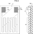
- FIG.3 (a) is a top view which shows typically an example of the film heater of the 1st aspect of this invention using the exterior sheet
- FIG.3 (b) is sectional drawing which shows typically an example of the film heater of this invention using the exterior sheet
- the entire surface of the support sheet 1 on which the conductive pattern is formed is covered with the exterior sheet 3 except for the through-holes 31, so that the entire transparent sheet is formed from a transparent thermoplastic resin sheet. Even if a conductive pattern made of conductive wires is sandwiched between the support sheet 1 and the exterior sheet 3, the connection terminal portion 21 can be reliably electrically connected to an external power source.
- an antifouling layer, an antifogging layer, an antistatic layer, a hard coat layer, or the like may be formed on the surface of the exterior sheet.
- the adhesion layer in the 1st aspect of this invention, it can be set as the structure by which the adhesion layer was provided in the surface opposite to the surface in which the electroconductive pattern of the support sheet was provided as needed.
- the pressure-sensitive adhesive layer By using the pressure-sensitive adhesive layer, it can be easily attached to an adherend having an uneven shape.
- the adhesive layer for example, an acrylic, urethane, epoxy, rubber, polyester, cellulose, emulsion, or other adhesive can be used.
- curing agent, etc. can be used suitably as an additive for the characteristic improvement of an adhesive if needed.
- the thickness of the pressure-sensitive adhesive layer is not particularly limited as long as the adhesive strength can be obtained, and is usually 20 ⁇ m to 200 ⁇ m, preferably about 25 ⁇ m to 75 ⁇ m.
- the adhesive can be formed using an application method such as gravure coating, gravure reverse coating, comma coating, knife coating, die coating, or the like.
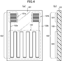
- FIG.4 (a) is a top view which shows typically the film heater of one Embodiment of the 2nd aspect of this invention.
- FIG.4 (b) is sectional drawing which shows typically the film heater of one Embodiment of the 2nd aspect of this invention.
- a conductive pattern made of conductive wires is provided on one surface of a support sheet 101 made of a transparent thermoplastic resin sheet, the other surface of the support sheet 101 has irregularities, and the conductive pattern is A pair of left and right connection terminal portions 121a and 121b, lead wires 122a and 122b extending from the connection terminal portions 121a and 121b, and a heater portion 123 continuing from the lead wires 122a and 122b, respectively.
- the heater portion as a whole may be non-linear.
- the conductive pattern is formed by a single continuous conductive line, and the connection terminal portions 121 a and 121 b are configured by a linear pattern in which conductive wires extending from the lead portions 122 a and 122 b are bent at a plurality of locations. Has been.
- the support sheet used for the film heater of the second aspect of the present invention is made of a transparent thermoplastic resin sheet.
- the transparent film heater as a whole can be produced suitably.
- a transparent film heater as a whole can be attached to various adherends without impairing the design of the adherend to be heated.
- thermoplastic resin sheet it can be easily attached to an adherend having a shape with unevenness, and in particular, when the adherend is a resin molded body, vacuum molding, hot press
- a film heater can be formed on the surface of the resin molded body by a molding method such as molding, laminate molding, in-mold molding, or insert molding.
- thermoplastic resin sheet ethylene-based resin, propylene-based resin, polyolefin-based resin, thermoplastic polyester-based resin, polyamide-based resin, polyvinyl chloride, polycarbonate, ABS resin, and the like can be used, and two or more of these are contained. You may do. In particular, it is preferable to use a polypropylene resin having excellent moldability, mechanical strength, flexibility, and weather resistance.
- An inorganic fine powder or organic filler, a dispersant, an antioxidant, a compatibilizing agent, an ultraviolet stabilizer, an antiblocking agent, an antistatic agent and the like can be appropriately added to the thermoplastic resin sheet.
- the thickness of the thermoplastic resin sheet is preferably 0.030 mm to 1.000 mm, more preferably 0.100 mm to 0.700 mm.
- the surface opposite to the surface on which the conductive pattern made of conductive wires of the transparent thermoplastic resin sheet serving as the support sheet is provided, that is, the surface to be bonded to the adherend has an uneven surface.
- the support sheet has a concavo-convex surface, the air is easily removed when the support sheet is bonded to the adherend, and it is difficult to include bubbles between the support sheet and the adherend that cause poor appearance or damage. Embossing etc. are mentioned as a method of forming an uneven surface in a thermoplastic resin sheet.
- the actual area (surface area) per unit area of the surface to be bonded to the adherend is increased by the space due to the unevenness and the undulating surface, and the adhesion between the adherend and the support sheet can be improved.
- the level of the undulating surface due to the unevenness can range from a fine size such as a few microns deep to a very large one such as several tens of millimeters, but in order to make the unevenness difficult to see after bonding to the adherend.
- the thickness may be 5 ⁇ m to 50 ⁇ m, preferably 10 ⁇ m to 30 ⁇ m.
- the irregular shape is not particularly limited, and may be a geometrical shape such as a waveform, sphere, circle, ellipse, trapezoid, or cone, as well as a fine satin or various picture patterns, etc. In order to do so, the shape may include a waveform.
- the conductive pattern can also be formed by printing using conductive ink such as silver paste or etching of metal foil such as copper foil.
- conductive ink such as silver paste or etching of metal foil such as copper foil.
- the conductive pattern it is possible to easily form a heater part, a lead part, and a connection terminal part as a single continuous line by forming a circular conductive wire in a predetermined pattern in a cross-sectional view having a constant diameter. It is preferable in that it can be performed.
- the conductive pattern is composed of conductive lines, the conductive lines preferably include at least a metal line, and more preferably, the metal line is covered with a self-bonding insulating film. can do.
- metal wire for example, a metal wire such as copper, iron, gold, copper nickel, nickel chrome, iron nickel chrome or the like can be used, but other materials can be used as long as they have conductivity. From the viewpoint of electrical resistance, durability, and cost, it is preferable to use copper as the metal wire or a copper alloy in which zinc, lead, tin, silver, aluminum, nickel, beryllium, zirconium, or the like is used alone or in combination.
- the insulating film covering the metal wire is an insulating resin film, and the conductive wire covered with the insulating film can be a commercially available enameled wire.
- Specific examples of the insulating resin coating include polyester, polyethylene, polyurethane, polyvinyl chloride, polyamide, polyimide, polyesterimide, polyamideimide, and fluororesin.
- the insulating coating is typically black, but the insulating coating may be colored in any color according to the color of the adherend to be heated.
- the diameter of the conductive wire constituting the conductive pattern is, for example, 0.03 mm to 0.20 mm. Although it may not be easy to form a thin conductive wire, it should be as thin as possible so as not to impair the design of the adherend to be heated.
- the diameter of the conductive wire is preferably 0.05 mm to 0 mm. .15 mm.
- the length of the conductive line can be determined according to the pattern form of the conductive pattern.
- the conductive pattern can be typically formed by drawing a conductive line on a support sheet, drawing a predetermined pattern form, and fixing the conductive line by embedding at least the surface of the support sheet.
- a method for embedding the conductive wire in the surface of the support sheet for example, it is desirable to embed the conductive wire in the surface of the support sheet by utilizing the principle of ultrasonic fusion.
- ultrasonic fusion it is possible to use a wiring drawing apparatus capable of melting the surface of a support sheet made of a thermoplastic resin while drawing out the conductive wires and embedding the conductive wires in the surface of the support sheet.
- the conductive wire can be embedded on the surface of the support sheet by vibration and pressure while the conductive wire is fed onto the surface of the support sheet.
- the conductive pattern can be positioned on the support sheet, and the displacement of the conductive lines due to an external impact or the like can be suppressed.
- the degree of unevenness on the surface of the support sheet due to the placement of the conductive wire on the surface of the support sheet can be reduced.
- the conductive pattern 102 includes a pair of left and right connection terminal portions 121a and 121b, lead wires 122a and 122b extending from the connection terminal portions 121a and 121b, and a lead wire 122a and 122b as a whole.
- the non-linear heater portion 123 is provided as a continuous linear pattern made of one conductive wire.
- connection terminal portions 121a and 121b are formed in a meander shape in which the conductive wire is bent at a plurality of locations and meanders.
- the connection terminal portions 121a and 121b are formed by densely folding the folded lines by increasing the number of times of folding of the folded portions that fold and meander at a plurality of locations within a predetermined plane area.
- the meander shape is formed by repeating a relatively short bent portion and a relatively long straight portion, and the number of the straight portions is 2 / mm or more. It is preferable that
- a conductive piece made of a metal plate can be further provided on the connection terminal portion in order to increase the connection efficiency with the external electrode.
- the metal plate for example, copper, copper alloy, iron, iron and nickel alloy, or the like can be used.
- the conductive wire is covered with an insulating film, the insulating film covering the conductive wire of the connection terminal portion is removed to expose the internal metal wire.
- an exposing method cutting with a milling device or the like is possible, but the insulating coating can also be melted and removed by heat when soldered to a metal plate or external electrode.
- the heater portion 123 is formed by being routed from lead wires 122a and 122b extending from the pair of left and right connection terminal portions 121a and 121b.
- the heater portion 123 is a bent portion having a relatively short length. And a relatively long straight line portion are repeated, and the whole is a non-linear linear pattern that bends at a plurality of places and meanders.
- the pattern of the heater portion can be an arbitrary pattern in consideration of the shape of the adherend, the heating area, and the heating efficiency, and may be a curvilinear shape that does not include a straight portion or a spiral shape. In FIG.
- the conductive pattern is composed of a pair of left and right connection terminal portions 121a and 121b and a pair of left and right lead portions 122a and 122b with the heater portion 123 as the center, and the conductive wire starts from the end of one connection terminal portion 121a.
- a meander-shaped connecting portion 121a is formed, a lead wire 122a is extended from the other end of the connecting terminal portion 121a, and a heater portion 123 is formed by a conductive wire routed from the lead wire 122a.
- the other lead wire 122b is extended from the portion 123, and one continuous wire heater portion 123, the lead portion 122, and the connection terminal portion 121 are formed by one conductive wire extending to the other connection terminal portion 121b.
- an exterior sheet made of another transparent thermoplastic resin sheet covering the conductive pattern is provided on one surface of the support sheet provided with the conductive pattern, and the exterior
- the sheet may be a film heater provided with a through hole that exposes at least a part of the connection terminal portion to the outside.
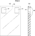
- FIG.5 (a) is a top view which shows typically an example of the exterior sheet
- FIG.5 (b) is sectional drawing which shows typically an example of the exterior sheet
- a through-hole 131 that exposes at least a part of the connection terminal portion of the film heater to the outside is provided in the exterior sheet 103 having substantially the same shape as the support sheet.
- the exterior sheet can be the same thermoplastic resin sheet as the support sheet, and the exterior sheet can be bonded by applying heat treatment and / or press treatment to one surface of the support sheet on which the conductive pattern is formed. it can. In the bonding, an adhesive layer, an adhesive layer, a heat seal layer, or the like may be interposed between the support sheet and the exterior sheet as necessary.
- the exterior sheet is provided with a through hole that exposes at least a part of the connection terminal portion to the outside. For forming the through hole of the exterior sheet for exposing the connection terminal portion, it is possible to use a cutting means such as punching with a mold or a laser device, specifically, a BIK blade, a cutting blade, a laser cutter, or A milling device or the like can be used.
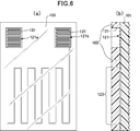
- FIG.6 (a) is a top view which shows typically an example of the film heater of the 2nd aspect of this invention using the exterior sheet
- FIG.6 (b) is sectional drawing which shows typically an example of the film heater of the 2nd aspect of this invention using the exterior sheet
- the entire surface of one surface of the support sheet 101 on which the conductive pattern is formed is covered with the exterior sheet 103 except for the through-holes 131, so that a transparent heat can be obtained as a whole. Even if the conductive pattern made of conductive wires is sandwiched between the support sheet 101 made of a plastic resin sheet and the exterior sheet 103, the connection terminal portion 121 can be reliably electrically connected to an external power source. .
- an antifouling layer, an antifogging layer, an antistatic layer, a hard coat layer, or the like may be formed on the surface of the exterior sheet.
- the 2nd aspect of this invention it can be set as the structure by which the adhesion layer was provided on the other uneven surface of the support sheet if needed.
- an adhesive layer By using an adhesive layer, it can be easily attached to an adherend.
- the adhesive layer for example, an acrylic, urethane, epoxy, rubber, polyester, cellulose, emulsion, or other adhesive can be used.
- curing agent, etc. can be used suitably as an additive for the characteristic improvement of an adhesive if needed.
- the thickness of the pressure-sensitive adhesive layer is not particularly limited as long as the adhesive strength can be obtained, and is usually 20 ⁇ m to 200 ⁇ m, preferably about 25 ⁇ m to 75 ⁇ m.
- the adhesive can be formed using an application method such as gravure coating, gravure reverse coating, comma coating, knife coating, die coating, or the like.
- Example 1 A thermoplastic resin sheet (polycarbonate sheet DPI-AO thickness 0.075 mm manufactured by Mitsubishi Plastics, Inc.) to be a support sheet is prepared, and a conductive wire (ELEKTRISOLA self-bonding coating conductor AB15 ⁇ 0.10 mm) is provided on the surface of the support sheet.
- the conductive pattern was formed by embedding using a wiring drawing apparatus equipped with an ultrasonic head (Rulamat WCE150, setting conditions: USP1200, speed 40%) as shown in FIG.
- the length of the lead portion (the length of the straight portion from the terminal portion to the first turn-up position) is 130 mm
- the heater portion has a straight portion of 90 mm
- the turn-up portion (pitch) of 10 mm
- the number of turns (the straight portion)
- the number of lines) was 8
- the connection terminal portion was a straight portion 17 mm, a folded portion (pitch) 0.3 mm, and the number of turns (the number of lines in the straight portion) 12 times.
- the film was cut into a length of 170 mm ⁇ width of 120 mm to produce a film heater.
- Example 2 A thermoplastic resin sheet (polycarbonate sheet DPI-AO thickness 0.075 mm manufactured by Mitsubishi Plastics, Inc.) serving as an exterior sheet was prepared, and a 10 mm ⁇ 10 mm through hole was formed at a corresponding position of the connection terminal portion.
- the exterior sheet was bonded to the surface of the support sheet on which the conductive pattern of Example 1 was wired, and heated and pressed by a vacuum laminator (MVLP-500, temperature 180 ° C., pressure 0.5 MPa, manufactured by Meiki Seisakusho). Adhered sufficiently to the top. Finally, the film was cut into a length of 170 mm ⁇ width of 120 mm to produce a film heater.
- MVLP-500 vacuum laminator
- thermoplastic resin sheet (Polycarbonate sheet DPI-AO thickness 0.075 mm, manufactured by Mitsubishi Plastics, Inc.) is prepared as a support sheet, and a thermoplastic resin is formed by a metal plate having a flat surface and a metal plate having an embossed mold formed on the surface.
- the sheet was sandwiched and embossed by hot pressing with a vacuum laminator (MVLP-500 manufactured by Meiki Seisakusho, temperature 180 ° C., pressure 0.5 MPa) to form an uneven surface on one side of the support sheet.
- the concavo-convex surface was a continuous pattern having a waveform having a depth of about 20 ⁇ m.
- a conductive wire self-bonding film conductor AB15 ⁇ 0.10 mm manufactured by ELEKTRISOLA
- a wiring drawing device (Rulamat WCE150, setting condition: USP1200, speed 40%) equipped with an ultrasonic head.
- a conductive pattern as shown in FIG. 4 was formed by embedding.
- the length of the lead part (the length of the straight part from the terminal part to the first folding position) is 130 mm
- the heater part is 90 mm in the straight part, 10 mm in the folded part (pitch), and the number of foldings (the straight part)
- the number of lines is 8
- the connection terminal portion is a straight portion of 17 mm, a folded portion (pitch) of 0.3 mm, and the number of turns (the number of lines of the straight portion) is 12 times.
- the film was cut into a length of 170 mm ⁇ width of 120 mm to produce a film heater.
- Example 4 A thermoplastic resin sheet (polycarbonate sheet DPI-AO thickness 0.075 mm manufactured by Mitsubishi Plastics, Inc.) serving as an exterior sheet was prepared, and a 10 mm ⁇ 10 mm through hole was formed at a corresponding position of the connection terminal portion.
- An exterior sheet is bonded to the surface of the support sheet on which the conductive pattern of Example 3 is wired, and heated and pressed by a vacuum laminator (MVLP-500, temperature 180 ° C., pressure 0.5 MPa, manufactured by Meiki Seisakusho) on the support sheet. It was made to adhere enough. Finally, the film was cut into a length of 170 mm ⁇ width of 120 mm to produce a film heater.
- MVLP-500 vacuum laminator
Landscapes
- Surface Heating Bodies (AREA)
- Resistance Heating (AREA)
Abstract
Description
特許文献2には、柔軟性を有する面状の発熱部と、この発熱部を内包するよう形成された半硬化状態の半硬化樹脂被覆層と、を有する硬質面状発熱体製造用半硬化シートが開示されている。発熱部を内包する半硬化樹脂被覆層は、半硬化状態(Bステージ)であり、柔軟性および可塑性を有すると共に、その表面は粘着性を有しているため、あらゆる被着体の形状に対して追従し、貼付させることができることが記載されている。
また、特許文献1に開示されている発明のように両面粘着テープ、両面粘着フィルムを用いて被着体に貼着する場合は、被着体との間に気泡を含みやすく、外観が損なわれ、破損等の原因になりやすい。
特許文献2に開示されている発明は、特殊な樹脂被膜を用いる必要があり、光硬化法により半硬化樹脂被覆層を完全硬化させるなど特殊な設備が必要で、施工法が複雑になりやすい。
特許文献3に開示されている発明は、信号灯の表示窓がドーム形の形状である場合には効果的であるが、それ以外に使用することは難しい。
本発明は、また、加熱対象となる被着体の意匠性を損なうことなく、また、外観不良や破損等の原因となる気泡を含みにくく、凹凸があるような形状の被着体に対しても簡単に貼着することができ、成形性、機械的強度が高く、被着体に対する接着性に優れたフィルムヒータを提供することを目的とする。
本発明では、前記接続端子部は、前記導電線が複数箇所で折れ曲がったパターン、例えば、前記導電線が複数箇所で折れ曲がって蛇行するメアンダ形状で構成されているとよい。
本発明では、前記支持シートの前記導電性パターンが設けられた面に、前記導電性パターンを覆うように、前記支持シートとは別の透明な熱可塑性樹脂シートからなる外装シートが設けられ、該外装シートには、前記接続端子部の少なくとも一部を外部に露出させる貫通孔が設けられたフィルムヒータとすることができる。
本発明では、前記接続端子部上に、さらに金属板を設けることができる。
本発明では、前記導電性パターンを構成する導電線が、前記接続端子部を除いて、自己融着性の絶縁被膜により被覆されているとよい
本発明では、前記支持シートの導電性パターンが設けられた面とは反対の面に粘着層を設けた構成とすることができる。
本発明では、前記導電性パターンは、連続した一本の導電線で形成されているとよい。
また。本発明では、前記接続端子部は、前記導電線が複数箇所で折れ曲がったパターン、例えば、前記導電線が複数箇所で折れ曲がって蛇行するメアンダ形状で構成されているとよい。
本発明では、前記支持シートの前記一方の面側に、前記導電性パターンを覆うように、前記支持シートとは別の透明な熱可塑性樹脂シートからなる外装シートが設けられ、該外装シートには、前記接続端子部の少なくとも一部を外部に露出させる貫通孔が設けられているとよい。
本発明では、前記接続端子部上に、さらに金属板を設けることができる。
本発明では、前記導電性パターンを構成する導電線が、前記接続端子部を除いて、自己融着性の絶縁被膜により被覆されているとよい。
本発明では、前記支持シートの凹凸を有する他方の面に粘着層を設けることができる。
本発明の第二の態様によるフィルムヒータは、全体として透明なフィルムヒータであり、加熱対象となる被着体の意匠性を損なうことなく、さまざまな被着体に貼着可能である。また、支持シートの被着体との貼り合わせる面は凹凸面を有するため、被着体へ貼り合わせる時の空気の抜けがよくなり、外観不良や破損等の原因となる気泡を含みにくくなる。
支持シートと、存在する場合には外装シートに、熱可塑性樹脂シートを用いることにより、凹凸があるような形状の被着体に対しても簡単に貼着することができ、またインモールド転写も可能である。
導電性パターンを一本の導電線で連続形成することで、製造が容易となり、導電性パターンを形成した支持シートの全面を外装シートにより覆うことで、導電性パターンを保護することが可能になる。
図1(a)は本発明の第一の態様のフィルムヒータの一例を模式的に示す平面図である。図1(b)は本発明の第一の態様のフィルムヒータの一例を模式的に示す断面図である。
図1によると、透明な熱可塑性樹脂シートからなる支持シート1の一方の面に導電線からなる導電性パターン2が設けられている。導電性パターン2は、左右一対の接続端子部21a,21bと、これら接続端子部21a,21bからそれぞれ延びたリード線22a,22bと、リード線22a,22bから続くヒータ部23とが、一本の導電線からなる連続した線状パターンとして設けられている。この実施形態のように、ヒータ部を全体として非直線状のものとしてもよい。
また、熱可塑性樹脂シートを用いることにより、凹凸があるような形状の被着体に対して簡単に貼着することができ、特に、被着体が樹脂成形体の場合、真空成型、熱プレス成型、ラミネート成型、インモールド成型、インサート成型などの成型方法で、樹脂成形体の表面にフィルムヒータを形成することができる。
熱可塑性樹脂シートには、無機微細粉末あるいは有機フィラー、分散剤、酸化防止剤、相溶化剤、紫外線安定剤、アンチブロッキング剤、帯電防止剤等を適宜添加することができる。
熱可塑性樹脂シートの厚みは、好ましくは0.030mm~1.000mm、さらに好ましくは0.100mm~0.700mmである。
導電性パターンを導電線で構成する場合、その導電線は、少なくとも金属線を含んで構成されるのが好ましく、さらに好ましくは、金属線が自己融着性の絶縁被膜により被覆されてなるものとすることができる。金属線としては、例えば、銅、鉄、金、銅ニッケル、ニッケルクロム、鉄ニッケルクロム等の金属線を用いることができるが、導電性を有するものであれば他の材料を用いることもできる。電気抵抗や耐久性、コストの観点から、金属線として銅又は銅に亜鉛や鉛、錫、銀、アルミ、ニッケル、ベリリウム、ジルコニウムなどを単独もしくは複数組み合わせてある銅合金を用いることが好ましい。
導電性パターンを構成する導電線の直径は、例えば、0.03mm~0.20mmである。細い導電線を形成するのは容易ではない場合もあるが、加熱対象となる被着体の意匠性を損なわないためには導電線はできるだけ細いほうがよく、導電線の直径は好ましくは、0.05mm~0.15mmである。導電線の長さは、導電性パターンのパターン形態等に応じたものとすることができる。
支持シートの表面への導電線の埋め込み方法としては、例えば、超音波融着の原理を活用して導電線を支持シートの表面に埋め込むことが望ましい。超音波融着を行うに際しては、導電線を繰り出しながら熱可塑性樹脂からなる支持シートの表面を溶融させ、導電線を支持シートの表面に埋め込むことが可能な配線描画装置を用いることができる。このような配線描画装置が備える超音波ヘッドにより、導電線を支持シートの表面上へ繰り出しつつ、振動と加圧により支持シートの表面に導電線を埋め込むことができる。
支持シートの表面への導電線の埋め込みにより、支持シート上での導電性パターンの位置決めを行うことができ、外部からの衝撃等による導電線の位置ずれの抑制を図ることができる。また、支持シートの表面に導電線を埋め込むことで、支持シートの表面上に導電線を配置することによる支持シートの表面の凹凸の程度を低減することができる。
図1を参照すると、導電性パターン2は、左右一対の接続端子部21a,21bと、これら接続端子部21a,21bからそれぞれ延びたリード線22a,22bと、リード線22a,22bから続く全体として非直線状のヒータ部23とが、一本の導電線からなる連続した線状パターンとして設けられる。
一本の連続した導電線で、接続端子部と、リード線と、ヒータ部とを形成することで、製造工程を容易にでき、低コストのフィルムヒータを製造することが可能となる。
図1では、接続端子部21a,21bは、導電線が複数箇所で折れ曲がって蛇行するメアンダ形状で形成されている。この場合、接続端子部21a,21bは、複数個所で折れ曲がって蛇行する折り返し部分の折り返し回数を所定の平面積内で多くして折り返し線を密集させたものであることが好ましい。図1に示す実施形態のような場合、メアンダ形状は、相対的に長さの短い折れ曲がり部分と相対的に長さの長い直線部分とが繰り返され、この直線部分の本数が2本/mm以上となるようにすることが好適である。
導電線が絶縁被膜で被覆されている場合は、接続端子部の導電線を被覆する絶縁被膜を除去し、内部の金属線を露出させる。露出させる方法としては、ミーリング装置等による切削で可能であるが、金属板や外部電極と半田接続するときの熱で絶縁被膜を溶融除去することもできる。
図1では、導電性パターンは、ヒータ部23を中心に左右一対の接続端子部21a,21bと左右一対のリード部22a,22bからなり、導電線により一方の接続端子部21aの端部を始点としてメアンダ形状の接続部21aが形成され、この接続端子部21aの他端部からリード線22aが延ばされ、このリード線22aから引き回された導電線でヒータ部23が形成され、このヒータ部23から他方のリード線22bが延ばされ、他方の接続端子部21bへと続く一本の導電線で、一つの連続した線状のヒータ部23、リード部22、接続端子部21が形成されている。
図2では、フィルムヒータの支持シートと略同一形状の外装シート3に、フィルムヒータの接続端子部の少なくとも一部を外部に露出させる貫通孔31が設けられている。
外装シートには、接続端子部の少なくとも一部を外部に露出させる貫通孔が設けられる。接続端子部を露出させるための外装シートの貫通孔の形成には、金型による打ち抜きやレーザー装置等の切削手段を用いることができ、具体的には、ビク刃、切削刃、レーザーカッター、又はミーリング装置等を用いることができる。
図3に示す実施形態から解かるように、導電性パターンを形成した支持シート1の全面が貫通孔31を除いて外装シート3により覆われており、これにより全体として透明な熱可塑性樹脂シートからなる支持シート1と外装シート3の間に導電線からなる導電性パターンが挟持された構成であっても、接続端子部21は外部電源と確実に電気的に接続することができる。また、支持シートの表面のヒータ部とリード部を外装シートで覆って保護することが可能になる。
外装シートの表面には、必要により、防汚層や防曇層、帯電防止層、ハードコート層などを形成してもよい。
粘着層の厚みは接着力が得られる厚みであれば特に限定されず、通常は20μm~200μmとし、好ましくは25μm~75μm程度がよい。粘着層を形成する場合、粘着剤をグラビアコーティング、グラビアリバースコーティング、コンマコーティング、ナイフコーティング、ダイコーティング等の塗布方式を用いて形成できる。
図4によると、透明な熱可塑性樹脂シートからなる支持シート101の一方の面に導電線からなる導電性パターンが設けられ、支持シート101の他方の面は凹凸を有し、導電性パターンが、左右一対の接続端子部121a,121bと、これら接続端子部121a,121bからそれぞれ延びたリード線122a,122bと、リード線122a,122bから続くヒータ部123とを有する。この実施形態のように、ヒータ部を全体として非直線状のものとしてもよい。
図4では、導電性パターンは、連続した一本の導電線で形成され、接続端子部121a,121bは、リード部122a,122bからそれぞれ延びた導電線が複数箇所で折れ曲がった線状パターンで構成されている。
また、熱可塑性樹脂シートを用いることにより、凹凸があるような形状の被着体に対して簡単に貼着することができ、特に、被着体が樹脂成形体の場合、真空成型、熱プレス成型、ラミネート成型、インモールド成型、インサート成型などの成型方法で、樹脂成形体の表面にフィルムヒータを形成することができる。
熱可塑性樹脂シートには、無機微細粉末あるいは有機フィラー、分散剤、酸化防止剤、相溶化剤、紫外線安定剤、アンチブロッキング剤、帯電防止剤等を適宜添加することができる。
熱可塑性樹脂シートの厚みは、好ましくは0.030mm~1.000mm、さらに好ましくは0.100mm~0.700mmである。
支持シートとなる透明な熱可塑性樹脂シートの、導電線からなる導電性パターンが設けられた面とは反対の面、すなわち、被着体と貼り合わせる面は、凹凸面を有する。支持シートが凹凸面を有することにより、被着体へ貼り合わせる時の空気の抜けがよくなり、外観不良や破損等の原因となる気泡を支持シートと被着体との間に含みにくくなる。
熱可塑性樹脂シートに凹凸面を形成する方法としては、エンボス加工等が挙げられる。凹凸による空間や起伏面により、被着体と貼り合わせる面の単位面積当たりの実面積(表面積)が増加し、被着体と支持シートとの密着性を向上させることができる。
凹凸による起伏面の程度は、深さ数ミクロンといった微細な大きさから、数十ミリといった非常に大きなものまで可能であるが、被着体と貼り合わせた後に外観上凹凸を見えにくくする上では、5μm~50μm、好ましくは10μm~30μmであるとよい。
凹凸形状としては特に制約はなく、波形、球体、円形、楕円形、台形、錐体などの幾何学的形状の他、微細な梨地や各種絵模様などであってよいが、空気の抜けをよくする上では、波形を含む形状であるとよい。
導電性パターンを導電線で構成する場合、その導電線は、少なくとも金属線を含んで構成されるのが好ましく、さらに好ましくは、金属線が自己融着性の絶縁被膜により被覆されてなるものとすることができる。金属線としては、例えば、銅、鉄、金、銅ニッケル、ニッケルクロム、鉄ニッケルクロム等の金属線を用いることができるが、導電性を有するものであれば他の材料を用いることもできる。電気抵抗や耐久性、コストの観点から、金属線として銅又は銅に亜鉛や鉛、錫、銀、アルミ、ニッケル、ベリリウム、ジルコニウムなどを単独もしくは複数組み合わせてある銅合金を用いることが好ましい。
導電性パターンを構成する導電線の直径は、例えば、0.03mm~0.20mmである。細い導電線を形成するのは容易ではない場合もあるが、加熱対象となる被着体の意匠性を損なわないためにはできるだけ細いほうがよく、導電線の直径は好ましくは、0.05mm~0.15mmである。導電線の長さは、導電性パターンのパターン形態等に応じたものとすることができる。
支持シートの表面への導電線の埋め込み方法としては、例えば、超音波融着の原理を活用して導電線を支持シートの表面に埋め込むことが望ましい。超音波融着を行うに際しては、導電線を繰り出しながら熱可塑性樹脂からなる支持シートの表面を溶融させ、導電線を支持シートの表面に埋め込むことが可能な配線描画装置を用いることができる。このような配線描画装置が備える超音波ヘッドにより、導電線を支持シートの表面上へ繰り出しつつ、振動と加圧により支持シートの表面に導電線を埋め込むことができる。
支持シートの表面への導電線の埋め込みにより、支持シート上での導電性パターンの位置決めを行うことができ、外部からの衝撃等による導電線の位置ずれの抑制を図ることができる。また、支持シートの表面に導電線を埋め込むことで、支持シートの表面上に導電線を配置することによる支持シートの表面の凹凸の程度を低減することができる。
図4を参照すると、導電性パターン102は、左右一対の接続端子部121a,121bと、これら接続端子部121a,121bからそれぞれ延びたリード線122a,122bと、リード線122a,122bから続く全体として非直線状のヒータ部123とが、一本の導電線からなる連続した線状パターンとして設けられる。
一本の連続した導電線で、接続端子部と、リード線と、ヒータ部とを形成することで、製造工程を容易にでき、低コストのフィルムヒータを製造することが可能となる。
図4では、接続端子部121a,121bは、導電線が複数箇所で折れ曲がって蛇行するメアンダ形状で形成されている。この場合、接続端子部121a,121bは、複数個所で折れ曲がって蛇行する折り返し部分の折り返し回数を所定の平面積内で多くして折り返し線を密集させたものであることが好ましい。図4に示す実施形態のような場合、メアンダ形状は、相対的に長さの短い折れ曲がり部分と相対的に長さの長い直線部分とが繰り返され、この直線部分の本数が2本/mm以上となるようにすることが好適である。
導電線が絶縁被膜で被覆されている場合は、接続端子部の導電線を被覆する絶縁被膜を除去し、内部の金属線を露出させる。露出させる方法としては、ミーリング装置等による切削で可能であるが、金属板や外部電極と半田接続するときの熱で絶縁被膜を溶融除去することもできる。
図4では、導電性パターンは、ヒータ部123を中心に左右一対の接続端子部121a,121bと左右一対のリード部122a,122bからなり、導電線により一方の接続端子部121aの端部を始点としてメアンダ形状の接続部121aが形成され、この接続端子部121aの他端部からリード線122aが延ばされ、このリード線122aから引き回された導電線でヒータ部123が形成され、このヒータ部123から他方のリード線122bが延ばされ、他方の接続端子部121bへと続く一本の導電線で、一つの連続した線状のヒータ部123、リード部122、接続端子部121が形成されている。
図5では、支持シートと略同一形状の外装シート103に、フィルムヒータの接続端子部の少なくとも一部を外部に露出させる貫通孔131が設けられている。
外装シートには、接続端子部の少なくとも一部を外部に露出させる貫通孔が設けられる。接続端子部を露出させるための外装シートの貫通孔の形成には、金型による打ち抜きやレーザー装置等の切削手段を用いることができ、具体的には、ビク刃、切削刃、レーザーカッター、又はミーリング装置等を用いることができる。
図6に示す実施形態から解かるように、導電性パターンを形成した支持シート101の一方の面の全面が貫通孔131を除いて外装シート103により覆われており、これにより全体として透明な熱可塑性樹脂シートからなる支持シート101と外装シート103の間に導電線からなる導電性パターンが挟持された構成であっても、接続端子部121は外部電源と確実に電気的に接続することができる。また、支持シートの一方の面に形成されたヒータ部とリード部を外装シートで覆って保護することが可能になる。
外装シートの表面には、必要により、防汚層や防曇層、帯電防止層、ハードコート層などを形成してもよい。
粘着層の厚みは接着力が得られる厚みであれば特に限定されず、通常は20μm~200μmとし、好ましくは25μm~75μm程度がよい。粘着層を形成する場合、粘着剤をグラビアコーティング、グラビアリバースコーティング、コンマコーティング、ナイフコーティング、ダイコーティング等の塗布方式を用いて形成できる。
支持シートとなる熱可塑性樹脂シート(三菱樹脂株式会社製ポリカシートDPI-AO 厚み0.075mm)を準備し、支持シートの表面に導電線(ELEKTRISOLA社製自己融着被膜導線AB15φ0.10mm)を、超音波ヘッドを備えた配線描画装置(Ruhlamat社製WCE150、設定条件:USP1200、speed40%)を用いて埋め込み、図1に示すような導電性パターンを形成した。
導電性パターンは、リード部の長さ(端子部から最初の折り返し位置までの直線部分の長さ)が130mm、ヒータ部は、直線部分90mm、折り返し部分(ピッチ)10mm、折り返し回数(直線部分の線数)8回とし、接続端子部は、直線部分17mm、折り返し部分(ピッチ)0.3mm、折り返し回数(直線部分の線数)12回とした。最後に、縦170mmm×横120mmにカットし、フィルムヒータを作製した。
外装シートとなる熱可塑性樹脂シート(三菱樹脂株式会社製ポリカシートDPI-AO 厚み0.075mm)を準備し、接続端子部の対応する位置に 10mm×10mmの貫通孔を形成した。実施例1の導電性パターンを配線した支持シートの表面に外装シートを貼り合わせて、真空ラミネート機(名機製作所製MVLP-500、温度180℃、圧力0.5MPa)により加熱プレスし、支持シート上に十分に密着させた。最後に、縦170mmm×横120mmにカットし、フィルムヒータを作製した。
支持シートとなる熱可塑性樹脂シート(三菱樹脂株式会社製ポリカシートDPI-AO 厚み0.075mm)を準備し、表面が平坦な金属板と表面にエンボス型が形成された金属板とで熱可塑性樹脂シートを挟み、真空ラミネート機(名機製作所製MVLP-500、温度180℃ 圧力0.5MPa)により加熱プレスしてエンボス加工を行い、支持シートの片面に凹凸面を形成した。凹凸面は深さ約20μmの波形の連続模様とした。
支持シートの平坦な表面に導電線(ELEKTRISOLA社製自己融着被膜導線AB15φ0.10mm)を、超音波ヘッドを備えた配線描画装置(Ruhlamat社製WCE150、設定条件:USP1200、speed40%)を用いて埋め込み、図4に示すような導電性パターンを形成した。
導電性パターンは、リード部の長さ(端子部から最初の折り返し位置までの直線部分の長さ)が、130mm、ヒータ部は、直線部分90mm、折り返し部分(ピッチ)10mm、折り返し回数(直線部分の線数)8回とし、接続端子部は、直線部分17mm、折り返し部分(ピッチ)0.3mm、折り返し回数(直線部分の線数)12回とした。最後に、縦170mmm×横120mmにカットし、フィルムヒータを作製した。
外装シートとなる熱可塑性樹脂シート(三菱樹脂株式会社製ポリカシートDPI-AO 厚み0.075mm)を準備し、接続端子部の対応する位置に 10mm×10mmの貫通孔を形成した。実施例3の導電性パターンを配線した支持シートの表面に外装シートを貼り合わせて、真空ラミネート機(名機製作所製MVLP-500、温度180℃ 圧力0.5MPa)により加熱プレスし、支持シート上に十分に密着させた。最後に、縦170mmm×横120mmにカットし、フィルムヒータを作製した。
2、102 導電性パターン
21a、21b、121a、121b 接続端子部
22a、22b、122a、122b リード部
23、123 ヒータ部
3、103 外装シート
31、131 貫通孔
Claims (13)
- 透明な熱可塑性樹脂シートからなる支持シートの一方の面に、導電線からなる導電性パターンが設けられ、該導電性パターンは、接続端子部と、該接続端子部から延びたリード線と、該リード線から続くヒータ部とが、一本の導電線からなる連続した線状パターンとして設けられたことを特徴とするフィルムヒータ。
- 前記接続端子部は、前記導電線が複数箇所で折れ曲がったパターンで構成されている請求項1に記載のフィルムヒータ。
- 前記支持シートの前記導電性パターンが設けられた面に、前記導電性パターンを覆うように、前記支持シートとは別の透明な熱可塑性樹脂シートからなる外装シートが設けられ、該外装シートには、前記接続端子部の少なくとも一部を外部に露出させる貫通孔が設けられた請求項1又は2に記載のフィルムヒータ。
- 前記接続端子部上に、さらに金属板が設けられた請求項1~3のいずれか1項に記載のフィルムヒータ。
- 前記導電性パターンを構成する導電線が、前記接続端子部を除いて、自己融着性の絶縁被膜により被覆されてなる請求項1~4のいずれか1項に記載のフィルムヒータ。
- 前記支持シートの導電性パターンが設けられた面とは反対の面に粘着層が設けられた請求項1~5のいずれか1項に記載のフィルムヒータ。
- 透明な熱可塑性樹脂シートからなる支持シートの一方の面に導電線からなる導電性パターンが設けられ、該支持シートの他方の面は凹凸を有し、前記導電性パターンが、接続端子部と、該接続端子部から延びたリード線と、該リード線から続くヒータ部とを有するフィルムヒータ。
- 前記導電性パターンは、連続した一本の導電線で形成されている請求項7に記載のフィルムヒータ。
- 前記接続端子部は、前記リード部から延びた前記導電線が複数箇所で折れ曲がったパターンで構成されている請求項7又は8に記載のフィルムヒータ。
- 前記支持シートの前記一方の面側に、前記導電性パターンを覆うように、前記支持シートとは別の透明な熱可塑性樹脂シートからなる外装シートが設けられ、該外装シートには、前記接続端子部の少なくとも一部を外部に露出させる貫通孔が設けられた請求項7~9のいずれか1項記載のフィルムヒータ。
- 前記接続端子部上に、さらに金属板が設けられた請求項7~10のいずれか1項に記載のフィルムヒータ。
- 前記導電性パターンを構成する導電線が、前記接続端子部を除いて、自己融着性の絶縁被膜により被覆されてなる請求項7~11のいずれか1項に記載のフィルムヒータ。
- 前記支持シートの前記他方の面に粘着層が設けられた請求項7~12のいずれか1項に記載のフィルムヒータ。
Priority Applications (4)
| Application Number | Priority Date | Filing Date | Title |
|---|---|---|---|
| EP19776731.2A EP3780903A4 (en) | 2018-03-26 | 2019-03-19 | FILM HEATER |
| US17/041,890 US20210037614A1 (en) | 2018-03-26 | 2019-03-19 | Film Heater |
| CN201980022169.8A CN111919507A (zh) | 2018-03-26 | 2019-03-19 | 薄膜加热器 |
| KR1020207029638A KR20200132951A (ko) | 2018-03-26 | 2019-03-19 | 필름 히터 |
Applications Claiming Priority (4)
| Application Number | Priority Date | Filing Date | Title |
|---|---|---|---|
| JP2018057763A JP7121513B2 (ja) | 2018-03-26 | 2018-03-26 | フィルムヒータ |
| JP2018-057764 | 2018-03-26 | ||
| JP2018057764A JP7121514B2 (ja) | 2018-03-26 | 2018-03-26 | フィルムヒータ |
| JP2018-057763 | 2018-03-26 |
Publications (1)
| Publication Number | Publication Date |
|---|---|
| WO2019188575A1 true WO2019188575A1 (ja) | 2019-10-03 |
Family
ID=68061582
Family Applications (1)
| Application Number | Title | Priority Date | Filing Date |
|---|---|---|---|
| PCT/JP2019/011399 Ceased WO2019188575A1 (ja) | 2018-03-26 | 2019-03-19 | フィルムヒータ |
Country Status (5)
| Country | Link |
|---|---|
| US (1) | US20210037614A1 (ja) |
| EP (1) | EP3780903A4 (ja) |
| KR (1) | KR20200132951A (ja) |
| CN (1) | CN111919507A (ja) |
| WO (1) | WO2019188575A1 (ja) |
Cited By (1)
| Publication number | Priority date | Publication date | Assignee | Title |
|---|---|---|---|---|
| WO2020196417A1 (ja) * | 2019-03-28 | 2020-10-01 | 株式会社トッパンインフォメディア | フィルムヒータ |
Families Citing this family (2)
| Publication number | Priority date | Publication date | Assignee | Title |
|---|---|---|---|---|
| EP4436312A1 (en) * | 2023-03-24 | 2024-09-25 | TE Connectivity Solutions GmbH | Electrical heating unit for heating a heat shrink cover, electrical heating system, installation system, and manufacturing method |
| CN120730561A (zh) * | 2024-03-28 | 2025-09-30 | 法雷奥照明公司 | 加热膜、发光装置和机动车辆 |
Citations (8)
| Publication number | Priority date | Publication date | Assignee | Title |
|---|---|---|---|---|
| JPS6090790U (ja) * | 1983-11-28 | 1985-06-21 | 昭和電線電纜株式会社 | ヒ−テイングユニツト |
| JPH0553190U (ja) * | 1991-12-19 | 1993-07-13 | 株式会社クラベ | フィルムヒータ |
| JP2003257597A (ja) | 2002-02-28 | 2003-09-12 | Yukio Shiroo | 面状発熱体 |
| JP2006278138A (ja) | 2005-03-29 | 2006-10-12 | Nippon Zeon Co Ltd | 硬質面状発熱体製造用半硬化シート、硬質面状発熱体およびその製造方法 |
| JP2008077879A (ja) * | 2006-09-19 | 2008-04-03 | Fujifilm Corp | 透明フレキシブルフィルムヒーターおよびその製造方法 |
| JP2009252712A (ja) * | 2008-04-11 | 2009-10-29 | Yazaki Corp | 防水コネクタ及び防水コネクタの製造方法 |
| CN202231884U (zh) * | 2011-08-26 | 2012-05-23 | 东莞市国研电热材料有限公司 | 一种直发用陶瓷发热体 |
| JP2017004918A (ja) | 2015-06-10 | 2017-01-05 | 菱有工業株式会社 | 信号灯用の面状ヒータ及びそれを用いた氷雪付着防止方法 |
Family Cites Families (8)
| Publication number | Priority date | Publication date | Assignee | Title |
|---|---|---|---|---|
| JPS4925234Y1 (ja) * | 1969-01-29 | 1974-07-08 | ||
| US3887788A (en) * | 1972-10-13 | 1975-06-03 | Seibel & Seibel Enterprises | Condensation free mirror |
| TW250618B (ja) * | 1993-01-27 | 1995-07-01 | Mitsui Toatsu Chemicals | |
| DE19724320B4 (de) * | 1997-06-10 | 2008-07-10 | Robert Bosch Gmbh | Verfahren zur Herstellung einer heizbaren Antennenlinse |
| JP2002342729A (ja) * | 2001-05-16 | 2002-11-29 | Nittoku Eng Co Ltd | Icカードの製造方法 |
| FR2953677B1 (fr) * | 2009-12-04 | 2020-11-06 | Saint Gobain | Vitrage a fils conducteurs integres par ultrasons |
| JP2012134132A (ja) * | 2010-12-02 | 2012-07-12 | Ube Ind Ltd | フレキシブルヒーター及びその製造方法 |
| JP6376730B2 (ja) * | 2012-12-25 | 2018-08-22 | 株式会社クラベ | ヒータユニット及びステアリングホイール |
-
2019
- 2019-03-19 WO PCT/JP2019/011399 patent/WO2019188575A1/ja not_active Ceased
- 2019-03-19 EP EP19776731.2A patent/EP3780903A4/en not_active Withdrawn
- 2019-03-19 US US17/041,890 patent/US20210037614A1/en not_active Abandoned
- 2019-03-19 KR KR1020207029638A patent/KR20200132951A/ko not_active Ceased
- 2019-03-19 CN CN201980022169.8A patent/CN111919507A/zh active Pending
Patent Citations (8)
| Publication number | Priority date | Publication date | Assignee | Title |
|---|---|---|---|---|
| JPS6090790U (ja) * | 1983-11-28 | 1985-06-21 | 昭和電線電纜株式会社 | ヒ−テイングユニツト |
| JPH0553190U (ja) * | 1991-12-19 | 1993-07-13 | 株式会社クラベ | フィルムヒータ |
| JP2003257597A (ja) | 2002-02-28 | 2003-09-12 | Yukio Shiroo | 面状発熱体 |
| JP2006278138A (ja) | 2005-03-29 | 2006-10-12 | Nippon Zeon Co Ltd | 硬質面状発熱体製造用半硬化シート、硬質面状発熱体およびその製造方法 |
| JP2008077879A (ja) * | 2006-09-19 | 2008-04-03 | Fujifilm Corp | 透明フレキシブルフィルムヒーターおよびその製造方法 |
| JP2009252712A (ja) * | 2008-04-11 | 2009-10-29 | Yazaki Corp | 防水コネクタ及び防水コネクタの製造方法 |
| CN202231884U (zh) * | 2011-08-26 | 2012-05-23 | 东莞市国研电热材料有限公司 | 一种直发用陶瓷发热体 |
| JP2017004918A (ja) | 2015-06-10 | 2017-01-05 | 菱有工業株式会社 | 信号灯用の面状ヒータ及びそれを用いた氷雪付着防止方法 |
Non-Patent Citations (1)
| Title |
|---|
| See also references of EP3780903A4 |
Cited By (1)
| Publication number | Priority date | Publication date | Assignee | Title |
|---|---|---|---|---|
| WO2020196417A1 (ja) * | 2019-03-28 | 2020-10-01 | 株式会社トッパンインフォメディア | フィルムヒータ |
Also Published As
| Publication number | Publication date |
|---|---|
| CN111919507A (zh) | 2020-11-10 |
| EP3780903A4 (en) | 2021-12-22 |
| EP3780903A1 (en) | 2021-02-17 |
| US20210037614A1 (en) | 2021-02-04 |
| KR20200132951A (ko) | 2020-11-25 |
Similar Documents
| Publication | Publication Date | Title |
|---|---|---|
| JP7520910B2 (ja) | フィルムヒータ | |
| WO2019188575A1 (ja) | フィルムヒータ | |
| CN112154522B (zh) | 配线部件 | |
| JP2021514114A5 (ja) | ||
| US10165689B1 (en) | Method for forming circuits for three-dimensional parts and devices formed thereby | |
| TW201429379A (zh) | 層疊膜和遮罩印刷佈線板 | |
| TW201943054A (zh) | 電磁波屏蔽膜、屏蔽印刷電路板及屏蔽印刷電路板之製造方法 | |
| JP7520911B2 (ja) | フィルムヒータ | |
| JP7249187B2 (ja) | フィルムヒータ | |
| CN107046766A (zh) | 柔性印制薄膜电路及系统 | |
| JP7332317B2 (ja) | フィルムヒータ | |
| JP6422586B2 (ja) | プリント配線板の製造方法ならびに該方法に用いられるプリント配線板保護フィルムおよびシート状積層体 | |
| CN206907790U (zh) | 印刷导电结构以及包括印刷导电结构的发光模块 | |
| WO2020196417A1 (ja) | フィルムヒータ | |
| WO2021106713A1 (ja) | 配線板の製造方法及び配線板、並びに、成形品の製造方法及び成形品 | |
| JP7235711B2 (ja) | 自動車用ランプカバーの電熱部材の製造方法 | |
| US11648766B1 (en) | Process for making a flexible foil heater | |
| JP2015050206A (ja) | 配線部材 | |
| JP7026367B1 (ja) | 配線基板及びその製造方法 | |
| JP2015012099A (ja) | フレキシブルプリント配線板及びフレキシブルプリント配線板の製造方法 | |
| JP2021044349A (ja) | 電磁波シールドフィルムの製造方法、及び電磁波シールドフィルム付きプリント配線板の製造方法 | |
| TWI904645B (zh) | 曲面加熱裝置以及立體圖案物件轉移方法 | |
| JP2021044342A (ja) | 電磁波シールドフィルムの製造方法、及び電磁波シールドフィルム付きプリント配線板の製造方法 | |
| JP2019079592A (ja) | 入力装置およびその製造方法 | |
| JP2024044119A (ja) | 透明フィルムヒータ |
Legal Events
| Date | Code | Title | Description |
|---|---|---|---|
| 121 | Ep: the epo has been informed by wipo that ep was designated in this application |
Ref document number: 19776731 Country of ref document: EP Kind code of ref document: A1 |
|
| NENP | Non-entry into the national phase |
Ref country code: DE |
|
| ENP | Entry into the national phase |
Ref document number: 20207029638 Country of ref document: KR Kind code of ref document: A |
|
| ENP | Entry into the national phase |
Ref document number: 2019776731 Country of ref document: EP Effective date: 20201026 |
|
| WWW | Wipo information: withdrawn in national office |
Ref document number: 2019776731 Country of ref document: EP |