WO2019188575A1 - Dispositif de chauffage à film - Google Patents
Dispositif de chauffage à film Download PDFInfo
- Publication number
- WO2019188575A1 WO2019188575A1 PCT/JP2019/011399 JP2019011399W WO2019188575A1 WO 2019188575 A1 WO2019188575 A1 WO 2019188575A1 JP 2019011399 W JP2019011399 W JP 2019011399W WO 2019188575 A1 WO2019188575 A1 WO 2019188575A1
- Authority
- WO
- WIPO (PCT)
- Prior art keywords
- connection terminal
- conductive
- film heater
- sheet
- support sheet
- Prior art date
- Legal status (The legal status is an assumption and is not a legal conclusion. Google has not performed a legal analysis and makes no representation as to the accuracy of the status listed.)
- Ceased
Links
Images


Classifications
-
- H—ELECTRICITY
- H05—ELECTRIC TECHNIQUES NOT OTHERWISE PROVIDED FOR
- H05B—ELECTRIC HEATING; ELECTRIC LIGHT SOURCES NOT OTHERWISE PROVIDED FOR; CIRCUIT ARRANGEMENTS FOR ELECTRIC LIGHT SOURCES, IN GENERAL
- H05B3/00—Ohmic-resistance heating
- H05B3/84—Heating arrangements specially adapted for transparent or reflecting areas, e.g. for demisting or de-icing windows, mirrors or vehicle windshields
-
- H—ELECTRICITY
- H05—ELECTRIC TECHNIQUES NOT OTHERWISE PROVIDED FOR
- H05B—ELECTRIC HEATING; ELECTRIC LIGHT SOURCES NOT OTHERWISE PROVIDED FOR; CIRCUIT ARRANGEMENTS FOR ELECTRIC LIGHT SOURCES, IN GENERAL
- H05B3/00—Ohmic-resistance heating
- H05B3/20—Heating elements having extended surface area substantially in a two-dimensional [2D] plane, e.g. plate-heater
- H05B3/34—Heating elements having extended surface area substantially in a two-dimensional [2D] plane, e.g. plate-heater flexible, e.g. heating nets or webs
- H05B3/36—Heating elements having extended surface area substantially in a two-dimensional [2D] plane, e.g. plate-heater flexible, e.g. heating nets or webs heating conductor embedded in insulating material
-
- H—ELECTRICITY
- H05—ELECTRIC TECHNIQUES NOT OTHERWISE PROVIDED FOR
- H05B—ELECTRIC HEATING; ELECTRIC LIGHT SOURCES NOT OTHERWISE PROVIDED FOR; CIRCUIT ARRANGEMENTS FOR ELECTRIC LIGHT SOURCES, IN GENERAL
- H05B3/00—Ohmic-resistance heating
- H05B3/02—Details
-
- H—ELECTRICITY
- H05—ELECTRIC TECHNIQUES NOT OTHERWISE PROVIDED FOR
- H05B—ELECTRIC HEATING; ELECTRIC LIGHT SOURCES NOT OTHERWISE PROVIDED FOR; CIRCUIT ARRANGEMENTS FOR ELECTRIC LIGHT SOURCES, IN GENERAL
- H05B3/00—Ohmic-resistance heating
- H05B3/02—Details
- H05B3/03—Electrodes
-
- H—ELECTRICITY
- H05—ELECTRIC TECHNIQUES NOT OTHERWISE PROVIDED FOR
- H05B—ELECTRIC HEATING; ELECTRIC LIGHT SOURCES NOT OTHERWISE PROVIDED FOR; CIRCUIT ARRANGEMENTS FOR ELECTRIC LIGHT SOURCES, IN GENERAL
- H05B3/00—Ohmic-resistance heating
- H05B3/02—Details
- H05B3/06—Heater elements structurally combined with coupling elements or holders
-
- H—ELECTRICITY
- H05—ELECTRIC TECHNIQUES NOT OTHERWISE PROVIDED FOR
- H05B—ELECTRIC HEATING; ELECTRIC LIGHT SOURCES NOT OTHERWISE PROVIDED FOR; CIRCUIT ARRANGEMENTS FOR ELECTRIC LIGHT SOURCES, IN GENERAL
- H05B3/00—Ohmic-resistance heating
- H05B3/20—Heating elements having extended surface area substantially in a two-dimensional [2D] plane, e.g. plate-heater
-
- H—ELECTRICITY
- H05—ELECTRIC TECHNIQUES NOT OTHERWISE PROVIDED FOR
- H05B—ELECTRIC HEATING; ELECTRIC LIGHT SOURCES NOT OTHERWISE PROVIDED FOR; CIRCUIT ARRANGEMENTS FOR ELECTRIC LIGHT SOURCES, IN GENERAL
- H05B3/00—Ohmic-resistance heating
- H05B3/20—Heating elements having extended surface area substantially in a two-dimensional [2D] plane, e.g. plate-heater
- H05B3/34—Heating elements having extended surface area substantially in a two-dimensional [2D] plane, e.g. plate-heater flexible, e.g. heating nets or webs
-
- H—ELECTRICITY
- H05—ELECTRIC TECHNIQUES NOT OTHERWISE PROVIDED FOR
- H05B—ELECTRIC HEATING; ELECTRIC LIGHT SOURCES NOT OTHERWISE PROVIDED FOR; CIRCUIT ARRANGEMENTS FOR ELECTRIC LIGHT SOURCES, IN GENERAL
- H05B2203/00—Aspects relating to Ohmic resistive heating covered by group H05B3/00
- H05B2203/002—Heaters using a particular layout for the resistive material or resistive elements
- H05B2203/003—Heaters using a particular layout for the resistive material or resistive elements using serpentine layout
-
- H—ELECTRICITY
- H05—ELECTRIC TECHNIQUES NOT OTHERWISE PROVIDED FOR
- H05B—ELECTRIC HEATING; ELECTRIC LIGHT SOURCES NOT OTHERWISE PROVIDED FOR; CIRCUIT ARRANGEMENTS FOR ELECTRIC LIGHT SOURCES, IN GENERAL
- H05B2203/00—Aspects relating to Ohmic resistive heating covered by group H05B3/00
- H05B2203/002—Heaters using a particular layout for the resistive material or resistive elements
- H05B2203/004—Heaters using a particular layout for the resistive material or resistive elements using zigzag layout
-
- H—ELECTRICITY
- H05—ELECTRIC TECHNIQUES NOT OTHERWISE PROVIDED FOR
- H05B—ELECTRIC HEATING; ELECTRIC LIGHT SOURCES NOT OTHERWISE PROVIDED FOR; CIRCUIT ARRANGEMENTS FOR ELECTRIC LIGHT SOURCES, IN GENERAL
- H05B2203/00—Aspects relating to Ohmic resistive heating covered by group H05B3/00
- H05B2203/013—Heaters using resistive films or coatings
Definitions
- the present invention relates to a film heater, and more particularly to a film heater in which a conductive pattern that can be electrically connected to an external power source is provided on a film.
- Patent Document 1 discloses a planar heating element in which a bare nichrome wire processed into an arbitrary shape is disposed inside two multilayer composite films via an adhesive layer made of an insulating material. In addition, it is described that this planar heating element is attached to a heating object with a double-sided adhesive tape, a double-sided adhesive film, or the like.
- Patent Document 2 discloses a semi-cured sheet for producing a hard planar heating element, which includes a sheet-like heat generating portion having flexibility and a semi-cured resin coating layer in a semi-cured state so as to enclose the heat generating portion. Is disclosed. The semi-cured resin coating layer that encloses the heat generating part is in a semi-cured state (B stage), has flexibility and plasticity, and has a sticky surface, so it can be applied to any adherend shape. It can be followed and pasted.
- Patent Document 3 a metal wire resistor formed in a predetermined pattern is provided on the surface or inside of a circular sheet-like flexible transparent substrate having a fan-shaped notch with a central angle of 90 degrees or less.
- a planar heater for signal lamps is disclosed, and linear portions of fan-shaped notches are brought into contact with or in close proximity to each other, and the flexible transparent substrate is transformed from a circular sheet into a conical sheet.
- a bare nichrome wire is disposed between two multilayer composite films using a wiring fixing adhesive layer, and the peripheral portion of the multilayer composite film is heat-sealed.
- the configuration is complicated.
- it is easy to contain a bubble between adherends, and an external appearance is impaired. It is easy to cause damage.
- the invention disclosed in Patent Document 2 requires the use of a special resin coating, requires special equipment such as completely curing the semi-cured resin coating layer by a photocuring method, and the construction method tends to be complicated.
- the invention disclosed in Patent Document 3 is effective when the display window of the signal lamp has a dome shape, but it is difficult to use it other than that.
- a conductive pattern made of conductive wires is provided on one surface of a support sheet made of a transparent thermoplastic resin sheet, and the conductive pattern includes a connection terminal portion and the connection
- the film heater is characterized in that a lead wire extending from the terminal portion and a heater portion continuing from the lead wire are provided as a continuous linear pattern made of one conductive wire.
- the connection terminal portion may be configured in a pattern in which the conductive wire is bent at a plurality of locations, for example, a meander shape in which the conductive wire is bent at a plurality of locations and meanders.
- an exterior sheet made of a transparent thermoplastic resin sheet different from the support sheet is provided on the surface of the support sheet on which the conductive pattern is provided so as to cover the conductive pattern
- the exterior sheet may be a film heater provided with a through hole that exposes at least a part of the connection terminal portion to the outside.
- a metal plate can be further provided on the connection terminal portion.
- the conductive wires constituting the conductive pattern may be covered with a self-bonding insulating film except for the connection terminal portion.
- the conductive pattern of the support sheet is provided. It can be set as the structure which provided the adhesion layer in the surface opposite to the provided surface.
- a conductive pattern made of conductive wires is provided on one surface of a support sheet made of a transparent thermoplastic resin sheet, and the other surface of the support sheet has irregularities,
- the conductive pattern is a film heater having a connection terminal portion, a lead wire extending from the connection terminal portion, and a heater portion continuing from the lead wire.
- the conductive pattern may be formed of a single continuous conductive line.
- the connection terminal portion may be configured in a pattern in which the conductive wire is bent at a plurality of locations, for example, a meander shape in which the conductive wire is bent at a plurality of locations and meanders.
- an exterior sheet made of a transparent thermoplastic resin sheet different from the support sheet is provided on the one surface side of the support sheet so as to cover the conductive pattern, A through hole that exposes at least a part of the connection terminal portion to the outside may be provided.
- a metal plate can be further provided on the connection terminal portion.
- the conductive wire constituting the conductive pattern may be covered with a self-bonding insulating film except for the connection terminal portion.
- an adhesion layer can be provided in the other surface which has the unevenness
- the film heater according to the first aspect of the present invention is a transparent film heater as a whole, and can be attached to various adherends without impairing the design of the adherend to be heated. Further, by using a thermoplastic resin sheet for the support sheet and, if present, the exterior sheet, it can be easily adhered to an adherend having a shape with irregularities, When the adherend is a resin molded body, in-mold transfer that can form a film heater on the surface of the resin molded body simultaneously with the resin molding is possible.
- the conductive pattern is composed of a single conductive line, the conductive pattern can be continuously formed with a single conductive line, facilitating manufacturing, and covering the entire surface of the support sheet on which the conductive pattern is formed with an exterior sheet.
- the film heater according to the second aspect of the present invention is a transparent film heater as a whole, and can be attached to various adherends without impairing the design of the adherend to be heated.
- the surface of the support sheet to be bonded to the adherend has an uneven surface, air is easily removed when the support sheet is bonded to the adherend, and it is difficult to include bubbles that may cause poor appearance or damage.
- a thermoplastic resin sheet for the support sheet and, if present, the exterior sheet it can be easily attached to an adherend having an uneven shape, and in-mold transfer is also possible. Is possible.
- By forming the conductive pattern continuously with one conductive line the manufacturing becomes easy, and the entire surface of the support sheet on which the conductive pattern is formed is covered with the exterior sheet, so that the conductive pattern can be protected. .
- the present invention is a film heater having good formability, high mechanical strength, and excellent adhesion to an adherend, and can be applied to various purposes such as prevention of adhesion to snow and snow, prevention of snow melting, fogging, and heat retention. For example, it can also be applied to automobile headlights, motorcycle grips and seats, outdoor lights, traffic lights, and the like.
- (A) is a top view which shows typically an example of the film heater of the 1st aspect of this invention, (b) is the sectional drawing.
- (A) is a top view which shows typically an example of the exterior sheet
- (A) is a top view which shows typically an example of the film heater of the 1st aspect of this invention using an exterior sheet, (b) is the sectional drawing.
- (A) is a top view which shows typically an example of the film heater by the 2nd aspect of this invention, (b) is the sectional drawing.
- (A) is a top view which shows typically an example of the exterior sheet
- (A) is a top view which shows typically an example of the film heater of the 2nd aspect of this invention using an exterior sheet, (b) is the sectional drawing.
- FIG.1 (a) is a top view which shows typically an example of the film heater of the 1st aspect of this invention.
- FIG.1 (b) is sectional drawing which shows typically an example of the film heater of the 1st aspect of this invention.
- a conductive pattern 2 made of a conductive wire is provided on one surface of a support sheet 1 made of a transparent thermoplastic resin sheet.
- the conductive pattern 2 includes a pair of left and right connection terminal portions 21a and 21b, lead wires 22a and 22b extending from the connection terminal portions 21a and 21b, and a heater portion 23 continuing from the lead wires 22a and 22b. It is provided as a continuous linear pattern of conductive wires.
- the heater portion as a whole may be non-linear.
- the support sheet used for the film heater according to the first aspect of the present invention is made of a transparent thermoplastic resin sheet.
- the transparent film heater as a whole can be produced suitably.
- a transparent film heater as a whole can be attached to various adherends without impairing the design of the adherend to be heated.
- thermoplastic resin sheet it can be easily attached to an adherend having a shape with unevenness, and in particular, when the adherend is a resin molded body, vacuum molding, hot press
- a film heater can be formed on the surface of the resin molded body by a molding method such as molding, laminate molding, in-mold molding, or insert molding.
- thermoplastic resin sheet ethylene-based resin, propylene-based resin, polyolefin-based resin, thermoplastic polyester-based resin, polyamide-based resin, polyvinyl chloride, polycarbonate, ABS resin, and the like can be used, and two or more of these are contained. You may do. In particular, it is preferable to use a polypropylene resin having excellent moldability, mechanical strength, flexibility, and weather resistance.
- An inorganic fine powder or organic filler, a dispersant, an antioxidant, a compatibilizing agent, an ultraviolet stabilizer, an antiblocking agent, an antistatic agent and the like can be appropriately added to the thermoplastic resin sheet.
- the thickness of the thermoplastic resin sheet is preferably 0.030 mm to 1.000 mm, more preferably 0.100 mm to 0.700 mm.
- the conductive pattern can also be formed by printing using conductive ink such as silver paste or etching of metal foil such as copper foil.
- conductive ink such as silver paste or etching of metal foil such as copper foil.
- the conductive pattern it is possible to easily form a heater part, a lead part, and a connection terminal part as a single continuous line by forming a circular conductive wire in a predetermined pattern in a cross-sectional view having a constant diameter. It is preferable in that it can be performed.
- the conductive pattern is composed of conductive lines, the conductive lines preferably include at least a metal line, and more preferably, the metal line is covered with a self-bonding insulating film. can do.
- metal wire for example, a metal wire such as copper, iron, gold, copper nickel, nickel chrome, iron nickel chrome or the like can be used, but other materials can be used as long as they have conductivity. From the viewpoint of electrical resistance, durability, and cost, it is preferable to use copper as the metal wire or a copper alloy in which zinc, lead, tin, silver, aluminum, nickel, beryllium, zirconium, or the like is used alone or in combination.
- the insulating film covering the metal wire is an insulating resin film, and the conductive wire covered with the insulating film can be a commercially available enameled wire.
- Specific examples of the insulating resin coating include polyester, polyethylene, polyurethane, polyvinyl chloride, polyamide, polyimide, polyesterimide, polyamideimide, and fluororesin.
- the insulating coating is typically black, but the insulating coating may be colored in any color according to the color of the adherend to be heated.
- the diameter of the conductive wire constituting the conductive pattern is, for example, 0.03 mm to 0.20 mm.
- the conductive wire should be as thin as possible in order not to impair the design of the adherend to be heated, and the diameter of the conductive wire is preferably 0. It is 05 mm to 0.15 mm.
- the length of the conductive line can be determined according to the pattern form of the conductive pattern.
- the conductive pattern can be typically formed by drawing a conductive line on a support sheet, drawing a predetermined pattern form, and fixing the conductive line by embedding at least the surface of the support sheet.
- a method for embedding the conductive wire in the surface of the support sheet for example, it is desirable to embed the conductive wire in the surface of the support sheet by utilizing the principle of ultrasonic fusion.
- ultrasonic fusion it is possible to use a wiring drawing apparatus capable of melting the surface of a support sheet made of a thermoplastic resin while drawing out the conductive wires and embedding the conductive wires in the surface of the support sheet.
- the conductive wire can be embedded on the surface of the support sheet by vibration and pressure while the conductive wire is fed onto the surface of the support sheet.
- the conductive pattern can be positioned on the support sheet, and the displacement of the conductive lines due to an external impact or the like can be suppressed.
- the degree of unevenness on the surface of the support sheet due to the placement of the conductive wire on the surface of the support sheet can be reduced.
- the conductive pattern 2 includes a pair of left and right connection terminal portions 21 a and 21 b, lead wires 22 a and 22 b extending from the connection terminal portions 21 a and 21 b, and the lead wires 22 a and 22 b as a whole.
- the non-linear heater portion 23 is provided as a continuous linear pattern made of a single conductive wire.
- connection terminal portions 21a and 21b are formed in a meander shape in which the conductive wires are bent at a plurality of locations and meander.
- the connection terminal portions 21a and 21b are formed by densely folding the folded lines by increasing the number of times of folding of the folded portions that fold and meander at a plurality of locations within a predetermined plane area.
- the meander shape is formed by repeating a relatively short bent portion and a relatively long straight portion, and the number of the straight portions is 2 / mm or more. It is preferable that
- a conductive piece made of a metal plate can be further provided on the connection terminal portion in order to increase the connection efficiency with the external electrode.
- the metal plate for example, copper, copper alloy, iron, iron and nickel alloy, or the like can be used.
- the conductive wire is covered with an insulating film, the insulating film covering the conductive wire of the connection terminal portion is removed to expose the internal metal wire.
- an exposing method cutting with a milling device or the like is possible, but the insulating coating can also be melted and removed by heat when soldered to a metal plate or external electrode.
- the heater portion 23 is formed by being routed from lead wires 22a and 22b extending from the pair of left and right connection terminal portions 21a and 21b.
- the heater portion 23 is a bent portion having a relatively short length. And a relatively long straight line portion are repeated, and the whole is a non-linear linear pattern that bends at a plurality of places and meanders.
- the pattern of the heater portion can be an arbitrary pattern in consideration of the shape of the adherend, the heating area, and the heating efficiency, and may be a curvilinear shape that does not include a straight portion or a spiral shape. In FIG.
- the conductive pattern is composed of a pair of left and right connection terminal portions 21 a and 21 b and a pair of left and right lead portions 22 a and 22 b with the heater portion 23 as the center, and starts from the end of one connection terminal portion 21 a by a conductive wire.
- a meander-shaped connecting portion 21a is formed, a lead wire 22a is extended from the other end of the connecting terminal portion 21a, and a heater portion 23 is formed by a conductive wire routed from the lead wire 22a.
- the other lead wire 22b is extended from the portion 23, and one continuous linear heater portion 23, the lead portion 22, and the connection terminal portion 21 are formed by one conductive wire extending to the other connection terminal portion 21b.
- an exterior sheet made of another transparent thermoplastic resin sheet covering the conductive pattern is provided on the surface of the support sheet provided with the conductive pattern,
- FIG.2 (a) is a top view which shows typically an example of the exterior sheet
- FIG.2 (b) is sectional drawing which shows typically an example of the exterior sheet
- a through-hole 31 that exposes at least a part of the connection terminal portion of the film heater to the outside is provided in the exterior sheet 3 having substantially the same shape as the support sheet of the film heater.
- the same thermoplastic resin sheet as the support sheet can be used, and the exterior sheet can be bonded by applying heat treatment and / or press treatment to the surface of the support sheet on which the conductive pattern is formed. .
- an adhesive layer, an adhesive layer, a heat seal layer, or the like may be interposed between the support sheet and the exterior sheet as necessary.
- the exterior sheet is provided with a through hole that exposes at least a part of the connection terminal portion to the outside.
- a cutting means such as punching with a mold or a laser device, specifically, a BIK blade, a cutting blade, a laser cutter, or A milling device or the like can be used.
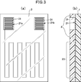
- FIG.3 (a) is a top view which shows typically an example of the film heater of the 1st aspect of this invention using the exterior sheet
- FIG.3 (b) is sectional drawing which shows typically an example of the film heater of this invention using the exterior sheet
- the entire surface of the support sheet 1 on which the conductive pattern is formed is covered with the exterior sheet 3 except for the through-holes 31, so that the entire transparent sheet is formed from a transparent thermoplastic resin sheet. Even if a conductive pattern made of conductive wires is sandwiched between the support sheet 1 and the exterior sheet 3, the connection terminal portion 21 can be reliably electrically connected to an external power source.
- an antifouling layer, an antifogging layer, an antistatic layer, a hard coat layer, or the like may be formed on the surface of the exterior sheet.
- the adhesion layer in the 1st aspect of this invention, it can be set as the structure by which the adhesion layer was provided in the surface opposite to the surface in which the electroconductive pattern of the support sheet was provided as needed.
- the pressure-sensitive adhesive layer By using the pressure-sensitive adhesive layer, it can be easily attached to an adherend having an uneven shape.
- the adhesive layer for example, an acrylic, urethane, epoxy, rubber, polyester, cellulose, emulsion, or other adhesive can be used.
- curing agent, etc. can be used suitably as an additive for the characteristic improvement of an adhesive if needed.
- the thickness of the pressure-sensitive adhesive layer is not particularly limited as long as the adhesive strength can be obtained, and is usually 20 ⁇ m to 200 ⁇ m, preferably about 25 ⁇ m to 75 ⁇ m.
- the adhesive can be formed using an application method such as gravure coating, gravure reverse coating, comma coating, knife coating, die coating, or the like.
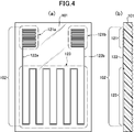
- FIG.4 (a) is a top view which shows typically the film heater of one Embodiment of the 2nd aspect of this invention.
- FIG.4 (b) is sectional drawing which shows typically the film heater of one Embodiment of the 2nd aspect of this invention.
- a conductive pattern made of conductive wires is provided on one surface of a support sheet 101 made of a transparent thermoplastic resin sheet, the other surface of the support sheet 101 has irregularities, and the conductive pattern is A pair of left and right connection terminal portions 121a and 121b, lead wires 122a and 122b extending from the connection terminal portions 121a and 121b, and a heater portion 123 continuing from the lead wires 122a and 122b, respectively.
- the heater portion as a whole may be non-linear.
- the conductive pattern is formed by a single continuous conductive line, and the connection terminal portions 121 a and 121 b are configured by a linear pattern in which conductive wires extending from the lead portions 122 a and 122 b are bent at a plurality of locations. Has been.
- the support sheet used for the film heater of the second aspect of the present invention is made of a transparent thermoplastic resin sheet.
- the transparent film heater as a whole can be produced suitably.
- a transparent film heater as a whole can be attached to various adherends without impairing the design of the adherend to be heated.
- thermoplastic resin sheet it can be easily attached to an adherend having a shape with unevenness, and in particular, when the adherend is a resin molded body, vacuum molding, hot press
- a film heater can be formed on the surface of the resin molded body by a molding method such as molding, laminate molding, in-mold molding, or insert molding.
- thermoplastic resin sheet ethylene-based resin, propylene-based resin, polyolefin-based resin, thermoplastic polyester-based resin, polyamide-based resin, polyvinyl chloride, polycarbonate, ABS resin, and the like can be used, and two or more of these are contained. You may do. In particular, it is preferable to use a polypropylene resin having excellent moldability, mechanical strength, flexibility, and weather resistance.
- An inorganic fine powder or organic filler, a dispersant, an antioxidant, a compatibilizing agent, an ultraviolet stabilizer, an antiblocking agent, an antistatic agent and the like can be appropriately added to the thermoplastic resin sheet.
- the thickness of the thermoplastic resin sheet is preferably 0.030 mm to 1.000 mm, more preferably 0.100 mm to 0.700 mm.
- the surface opposite to the surface on which the conductive pattern made of conductive wires of the transparent thermoplastic resin sheet serving as the support sheet is provided, that is, the surface to be bonded to the adherend has an uneven surface.
- the support sheet has a concavo-convex surface, the air is easily removed when the support sheet is bonded to the adherend, and it is difficult to include bubbles between the support sheet and the adherend that cause poor appearance or damage. Embossing etc. are mentioned as a method of forming an uneven surface in a thermoplastic resin sheet.
- the actual area (surface area) per unit area of the surface to be bonded to the adherend is increased by the space due to the unevenness and the undulating surface, and the adhesion between the adherend and the support sheet can be improved.
- the level of the undulating surface due to the unevenness can range from a fine size such as a few microns deep to a very large one such as several tens of millimeters, but in order to make the unevenness difficult to see after bonding to the adherend.
- the thickness may be 5 ⁇ m to 50 ⁇ m, preferably 10 ⁇ m to 30 ⁇ m.
- the irregular shape is not particularly limited, and may be a geometrical shape such as a waveform, sphere, circle, ellipse, trapezoid, or cone, as well as a fine satin or various picture patterns, etc. In order to do so, the shape may include a waveform.
- the conductive pattern can also be formed by printing using conductive ink such as silver paste or etching of metal foil such as copper foil.
- conductive ink such as silver paste or etching of metal foil such as copper foil.
- the conductive pattern it is possible to easily form a heater part, a lead part, and a connection terminal part as a single continuous line by forming a circular conductive wire in a predetermined pattern in a cross-sectional view having a constant diameter. It is preferable in that it can be performed.
- the conductive pattern is composed of conductive lines, the conductive lines preferably include at least a metal line, and more preferably, the metal line is covered with a self-bonding insulating film. can do.
- metal wire for example, a metal wire such as copper, iron, gold, copper nickel, nickel chrome, iron nickel chrome or the like can be used, but other materials can be used as long as they have conductivity. From the viewpoint of electrical resistance, durability, and cost, it is preferable to use copper as the metal wire or a copper alloy in which zinc, lead, tin, silver, aluminum, nickel, beryllium, zirconium, or the like is used alone or in combination.
- the insulating film covering the metal wire is an insulating resin film, and the conductive wire covered with the insulating film can be a commercially available enameled wire.
- Specific examples of the insulating resin coating include polyester, polyethylene, polyurethane, polyvinyl chloride, polyamide, polyimide, polyesterimide, polyamideimide, and fluororesin.
- the insulating coating is typically black, but the insulating coating may be colored in any color according to the color of the adherend to be heated.
- the diameter of the conductive wire constituting the conductive pattern is, for example, 0.03 mm to 0.20 mm. Although it may not be easy to form a thin conductive wire, it should be as thin as possible so as not to impair the design of the adherend to be heated.
- the diameter of the conductive wire is preferably 0.05 mm to 0 mm. .15 mm.
- the length of the conductive line can be determined according to the pattern form of the conductive pattern.
- the conductive pattern can be typically formed by drawing a conductive line on a support sheet, drawing a predetermined pattern form, and fixing the conductive line by embedding at least the surface of the support sheet.
- a method for embedding the conductive wire in the surface of the support sheet for example, it is desirable to embed the conductive wire in the surface of the support sheet by utilizing the principle of ultrasonic fusion.
- ultrasonic fusion it is possible to use a wiring drawing apparatus capable of melting the surface of a support sheet made of a thermoplastic resin while drawing out the conductive wires and embedding the conductive wires in the surface of the support sheet.
- the conductive wire can be embedded on the surface of the support sheet by vibration and pressure while the conductive wire is fed onto the surface of the support sheet.
- the conductive pattern can be positioned on the support sheet, and the displacement of the conductive lines due to an external impact or the like can be suppressed.
- the degree of unevenness on the surface of the support sheet due to the placement of the conductive wire on the surface of the support sheet can be reduced.
- the conductive pattern 102 includes a pair of left and right connection terminal portions 121a and 121b, lead wires 122a and 122b extending from the connection terminal portions 121a and 121b, and a lead wire 122a and 122b as a whole.
- the non-linear heater portion 123 is provided as a continuous linear pattern made of one conductive wire.
- connection terminal portions 121a and 121b are formed in a meander shape in which the conductive wire is bent at a plurality of locations and meanders.
- the connection terminal portions 121a and 121b are formed by densely folding the folded lines by increasing the number of times of folding of the folded portions that fold and meander at a plurality of locations within a predetermined plane area.
- the meander shape is formed by repeating a relatively short bent portion and a relatively long straight portion, and the number of the straight portions is 2 / mm or more. It is preferable that
- a conductive piece made of a metal plate can be further provided on the connection terminal portion in order to increase the connection efficiency with the external electrode.
- the metal plate for example, copper, copper alloy, iron, iron and nickel alloy, or the like can be used.
- the conductive wire is covered with an insulating film, the insulating film covering the conductive wire of the connection terminal portion is removed to expose the internal metal wire.
- an exposing method cutting with a milling device or the like is possible, but the insulating coating can also be melted and removed by heat when soldered to a metal plate or external electrode.
- the heater portion 123 is formed by being routed from lead wires 122a and 122b extending from the pair of left and right connection terminal portions 121a and 121b.
- the heater portion 123 is a bent portion having a relatively short length. And a relatively long straight line portion are repeated, and the whole is a non-linear linear pattern that bends at a plurality of places and meanders.
- the pattern of the heater portion can be an arbitrary pattern in consideration of the shape of the adherend, the heating area, and the heating efficiency, and may be a curvilinear shape that does not include a straight portion or a spiral shape. In FIG.
- the conductive pattern is composed of a pair of left and right connection terminal portions 121a and 121b and a pair of left and right lead portions 122a and 122b with the heater portion 123 as the center, and the conductive wire starts from the end of one connection terminal portion 121a.
- a meander-shaped connecting portion 121a is formed, a lead wire 122a is extended from the other end of the connecting terminal portion 121a, and a heater portion 123 is formed by a conductive wire routed from the lead wire 122a.
- the other lead wire 122b is extended from the portion 123, and one continuous wire heater portion 123, the lead portion 122, and the connection terminal portion 121 are formed by one conductive wire extending to the other connection terminal portion 121b.
- an exterior sheet made of another transparent thermoplastic resin sheet covering the conductive pattern is provided on one surface of the support sheet provided with the conductive pattern, and the exterior
- the sheet may be a film heater provided with a through hole that exposes at least a part of the connection terminal portion to the outside.
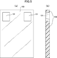
- FIG.5 (a) is a top view which shows typically an example of the exterior sheet
- FIG.5 (b) is sectional drawing which shows typically an example of the exterior sheet
- a through-hole 131 that exposes at least a part of the connection terminal portion of the film heater to the outside is provided in the exterior sheet 103 having substantially the same shape as the support sheet.
- the exterior sheet can be the same thermoplastic resin sheet as the support sheet, and the exterior sheet can be bonded by applying heat treatment and / or press treatment to one surface of the support sheet on which the conductive pattern is formed. it can. In the bonding, an adhesive layer, an adhesive layer, a heat seal layer, or the like may be interposed between the support sheet and the exterior sheet as necessary.
- the exterior sheet is provided with a through hole that exposes at least a part of the connection terminal portion to the outside. For forming the through hole of the exterior sheet for exposing the connection terminal portion, it is possible to use a cutting means such as punching with a mold or a laser device, specifically, a BIK blade, a cutting blade, a laser cutter, or A milling device or the like can be used.
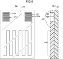
- FIG.6 (a) is a top view which shows typically an example of the film heater of the 2nd aspect of this invention using the exterior sheet
- FIG.6 (b) is sectional drawing which shows typically an example of the film heater of the 2nd aspect of this invention using the exterior sheet
- the entire surface of one surface of the support sheet 101 on which the conductive pattern is formed is covered with the exterior sheet 103 except for the through-holes 131, so that a transparent heat can be obtained as a whole. Even if the conductive pattern made of conductive wires is sandwiched between the support sheet 101 made of a plastic resin sheet and the exterior sheet 103, the connection terminal portion 121 can be reliably electrically connected to an external power source. .
- an antifouling layer, an antifogging layer, an antistatic layer, a hard coat layer, or the like may be formed on the surface of the exterior sheet.
- the 2nd aspect of this invention it can be set as the structure by which the adhesion layer was provided on the other uneven surface of the support sheet if needed.
- an adhesive layer By using an adhesive layer, it can be easily attached to an adherend.
- the adhesive layer for example, an acrylic, urethane, epoxy, rubber, polyester, cellulose, emulsion, or other adhesive can be used.
- curing agent, etc. can be used suitably as an additive for the characteristic improvement of an adhesive if needed.
- the thickness of the pressure-sensitive adhesive layer is not particularly limited as long as the adhesive strength can be obtained, and is usually 20 ⁇ m to 200 ⁇ m, preferably about 25 ⁇ m to 75 ⁇ m.
- the adhesive can be formed using an application method such as gravure coating, gravure reverse coating, comma coating, knife coating, die coating, or the like.
- Example 1 A thermoplastic resin sheet (polycarbonate sheet DPI-AO thickness 0.075 mm manufactured by Mitsubishi Plastics, Inc.) to be a support sheet is prepared, and a conductive wire (ELEKTRISOLA self-bonding coating conductor AB15 ⁇ 0.10 mm) is provided on the surface of the support sheet.
- the conductive pattern was formed by embedding using a wiring drawing apparatus equipped with an ultrasonic head (Rulamat WCE150, setting conditions: USP1200, speed 40%) as shown in FIG.
- the length of the lead portion (the length of the straight portion from the terminal portion to the first turn-up position) is 130 mm
- the heater portion has a straight portion of 90 mm
- the turn-up portion (pitch) of 10 mm
- the number of turns (the straight portion)
- the number of lines) was 8
- the connection terminal portion was a straight portion 17 mm, a folded portion (pitch) 0.3 mm, and the number of turns (the number of lines in the straight portion) 12 times.
- the film was cut into a length of 170 mm ⁇ width of 120 mm to produce a film heater.
- Example 2 A thermoplastic resin sheet (polycarbonate sheet DPI-AO thickness 0.075 mm manufactured by Mitsubishi Plastics, Inc.) serving as an exterior sheet was prepared, and a 10 mm ⁇ 10 mm through hole was formed at a corresponding position of the connection terminal portion.
- the exterior sheet was bonded to the surface of the support sheet on which the conductive pattern of Example 1 was wired, and heated and pressed by a vacuum laminator (MVLP-500, temperature 180 ° C., pressure 0.5 MPa, manufactured by Meiki Seisakusho). Adhered sufficiently to the top. Finally, the film was cut into a length of 170 mm ⁇ width of 120 mm to produce a film heater.
- MVLP-500 vacuum laminator
- thermoplastic resin sheet (Polycarbonate sheet DPI-AO thickness 0.075 mm, manufactured by Mitsubishi Plastics, Inc.) is prepared as a support sheet, and a thermoplastic resin is formed by a metal plate having a flat surface and a metal plate having an embossed mold formed on the surface.
- the sheet was sandwiched and embossed by hot pressing with a vacuum laminator (MVLP-500 manufactured by Meiki Seisakusho, temperature 180 ° C., pressure 0.5 MPa) to form an uneven surface on one side of the support sheet.
- the concavo-convex surface was a continuous pattern having a waveform having a depth of about 20 ⁇ m.
- a conductive wire self-bonding film conductor AB15 ⁇ 0.10 mm manufactured by ELEKTRISOLA
- a wiring drawing device (Rulamat WCE150, setting condition: USP1200, speed 40%) equipped with an ultrasonic head.
- a conductive pattern as shown in FIG. 4 was formed by embedding.
- the length of the lead part (the length of the straight part from the terminal part to the first folding position) is 130 mm
- the heater part is 90 mm in the straight part, 10 mm in the folded part (pitch), and the number of foldings (the straight part)
- the number of lines is 8
- the connection terminal portion is a straight portion of 17 mm, a folded portion (pitch) of 0.3 mm, and the number of turns (the number of lines of the straight portion) is 12 times.
- the film was cut into a length of 170 mm ⁇ width of 120 mm to produce a film heater.
- Example 4 A thermoplastic resin sheet (polycarbonate sheet DPI-AO thickness 0.075 mm manufactured by Mitsubishi Plastics, Inc.) serving as an exterior sheet was prepared, and a 10 mm ⁇ 10 mm through hole was formed at a corresponding position of the connection terminal portion.
- An exterior sheet is bonded to the surface of the support sheet on which the conductive pattern of Example 3 is wired, and heated and pressed by a vacuum laminator (MVLP-500, temperature 180 ° C., pressure 0.5 MPa, manufactured by Meiki Seisakusho) on the support sheet. It was made to adhere enough. Finally, the film was cut into a length of 170 mm ⁇ width of 120 mm to produce a film heater.
- MVLP-500 vacuum laminator
Landscapes
- Surface Heating Bodies (AREA)
- Resistance Heating (AREA)
Abstract
Priority Applications (4)
| Application Number | Priority Date | Filing Date | Title |
|---|---|---|---|
| KR1020207029638A KR20200132951A (ko) | 2018-03-26 | 2019-03-19 | 필름 히터 |
| CN201980022169.8A CN111919507A (zh) | 2018-03-26 | 2019-03-19 | 薄膜加热器 |
| US17/041,890 US20210037614A1 (en) | 2018-03-26 | 2019-03-19 | Film Heater |
| EP19776731.2A EP3780903A4 (fr) | 2018-03-26 | 2019-03-19 | Dispositif de chauffage à film |
Applications Claiming Priority (4)
| Application Number | Priority Date | Filing Date | Title |
|---|---|---|---|
| JP2018057764A JP7121514B2 (ja) | 2018-03-26 | 2018-03-26 | フィルムヒータ |
| JP2018057763A JP7121513B2 (ja) | 2018-03-26 | 2018-03-26 | フィルムヒータ |
| JP2018-057764 | 2018-03-26 | ||
| JP2018-057763 | 2018-03-26 |
Publications (1)
| Publication Number | Publication Date |
|---|---|
| WO2019188575A1 true WO2019188575A1 (fr) | 2019-10-03 |
Family
ID=68061582
Family Applications (1)
| Application Number | Title | Priority Date | Filing Date |
|---|---|---|---|
| PCT/JP2019/011399 Ceased WO2019188575A1 (fr) | 2018-03-26 | 2019-03-19 | Dispositif de chauffage à film |
Country Status (5)
| Country | Link |
|---|---|
| US (1) | US20210037614A1 (fr) |
| EP (1) | EP3780903A4 (fr) |
| KR (1) | KR20200132951A (fr) |
| CN (1) | CN111919507A (fr) |
| WO (1) | WO2019188575A1 (fr) |
Cited By (1)
| Publication number | Priority date | Publication date | Assignee | Title |
|---|---|---|---|---|
| WO2020196417A1 (fr) * | 2019-03-28 | 2020-10-01 | 株式会社トッパンインフォメディア | Dispositif de chauffage à film |
Families Citing this family (2)
| Publication number | Priority date | Publication date | Assignee | Title |
|---|---|---|---|---|
| EP4436312A1 (fr) * | 2023-03-24 | 2024-09-25 | TE Connectivity Solutions GmbH | Unité de chauffage électrique pour chauffer une couverture thermorétractable, système de chauffage électrique, système d'installation et procédé de fabrication |
| CN120730561A (zh) * | 2024-03-28 | 2025-09-30 | 法雷奥照明公司 | 加热膜、发光装置和机动车辆 |
Citations (8)
| Publication number | Priority date | Publication date | Assignee | Title |
|---|---|---|---|---|
| JPS6090790U (ja) * | 1983-11-28 | 1985-06-21 | 昭和電線電纜株式会社 | ヒ−テイングユニツト |
| JPH0553190U (ja) * | 1991-12-19 | 1993-07-13 | 株式会社クラベ | フィルムヒータ |
| JP2003257597A (ja) | 2002-02-28 | 2003-09-12 | Yukio Shiroo | 面状発熱体 |
| JP2006278138A (ja) | 2005-03-29 | 2006-10-12 | Nippon Zeon Co Ltd | 硬質面状発熱体製造用半硬化シート、硬質面状発熱体およびその製造方法 |
| JP2008077879A (ja) * | 2006-09-19 | 2008-04-03 | Fujifilm Corp | 透明フレキシブルフィルムヒーターおよびその製造方法 |
| JP2009252712A (ja) * | 2008-04-11 | 2009-10-29 | Yazaki Corp | 防水コネクタ及び防水コネクタの製造方法 |
| CN202231884U (zh) * | 2011-08-26 | 2012-05-23 | 东莞市国研电热材料有限公司 | 一种直发用陶瓷发热体 |
| JP2017004918A (ja) | 2015-06-10 | 2017-01-05 | 菱有工業株式会社 | 信号灯用の面状ヒータ及びそれを用いた氷雪付着防止方法 |
Family Cites Families (8)
| Publication number | Priority date | Publication date | Assignee | Title |
|---|---|---|---|---|
| JPS4925234Y1 (fr) * | 1969-01-29 | 1974-07-08 | ||
| US3887788A (en) * | 1972-10-13 | 1975-06-03 | Seibel & Seibel Enterprises | Condensation free mirror |
| TW250618B (fr) * | 1993-01-27 | 1995-07-01 | Mitsui Toatsu Chemicals | |
| DE19724320B4 (de) * | 1997-06-10 | 2008-07-10 | Robert Bosch Gmbh | Verfahren zur Herstellung einer heizbaren Antennenlinse |
| JP2002342729A (ja) * | 2001-05-16 | 2002-11-29 | Nittoku Eng Co Ltd | Icカードの製造方法 |
| FR2953677B1 (fr) * | 2009-12-04 | 2020-11-06 | Saint Gobain | Vitrage a fils conducteurs integres par ultrasons |
| JP2012134132A (ja) * | 2010-12-02 | 2012-07-12 | Ube Ind Ltd | フレキシブルヒーター及びその製造方法 |
| JP6376730B2 (ja) * | 2012-12-25 | 2018-08-22 | 株式会社クラベ | ヒータユニット及びステアリングホイール |
-
2019
- 2019-03-19 EP EP19776731.2A patent/EP3780903A4/fr not_active Withdrawn
- 2019-03-19 CN CN201980022169.8A patent/CN111919507A/zh active Pending
- 2019-03-19 KR KR1020207029638A patent/KR20200132951A/ko not_active Ceased
- 2019-03-19 US US17/041,890 patent/US20210037614A1/en not_active Abandoned
- 2019-03-19 WO PCT/JP2019/011399 patent/WO2019188575A1/fr not_active Ceased
Patent Citations (8)
| Publication number | Priority date | Publication date | Assignee | Title |
|---|---|---|---|---|
| JPS6090790U (ja) * | 1983-11-28 | 1985-06-21 | 昭和電線電纜株式会社 | ヒ−テイングユニツト |
| JPH0553190U (ja) * | 1991-12-19 | 1993-07-13 | 株式会社クラベ | フィルムヒータ |
| JP2003257597A (ja) | 2002-02-28 | 2003-09-12 | Yukio Shiroo | 面状発熱体 |
| JP2006278138A (ja) | 2005-03-29 | 2006-10-12 | Nippon Zeon Co Ltd | 硬質面状発熱体製造用半硬化シート、硬質面状発熱体およびその製造方法 |
| JP2008077879A (ja) * | 2006-09-19 | 2008-04-03 | Fujifilm Corp | 透明フレキシブルフィルムヒーターおよびその製造方法 |
| JP2009252712A (ja) * | 2008-04-11 | 2009-10-29 | Yazaki Corp | 防水コネクタ及び防水コネクタの製造方法 |
| CN202231884U (zh) * | 2011-08-26 | 2012-05-23 | 东莞市国研电热材料有限公司 | 一种直发用陶瓷发热体 |
| JP2017004918A (ja) | 2015-06-10 | 2017-01-05 | 菱有工業株式会社 | 信号灯用の面状ヒータ及びそれを用いた氷雪付着防止方法 |
Non-Patent Citations (1)
| Title |
|---|
| See also references of EP3780903A4 |
Cited By (1)
| Publication number | Priority date | Publication date | Assignee | Title |
|---|---|---|---|---|
| WO2020196417A1 (fr) * | 2019-03-28 | 2020-10-01 | 株式会社トッパンインフォメディア | Dispositif de chauffage à film |
Also Published As
| Publication number | Publication date |
|---|---|
| EP3780903A4 (fr) | 2021-12-22 |
| KR20200132951A (ko) | 2020-11-25 |
| EP3780903A1 (fr) | 2021-02-17 |
| CN111919507A (zh) | 2020-11-10 |
| US20210037614A1 (en) | 2021-02-04 |
Similar Documents
| Publication | Publication Date | Title |
|---|---|---|
| JP7520910B2 (ja) | フィルムヒータ | |
| JP6184025B2 (ja) | 電磁波シールドフィルムおよび電磁波シールドフィルム付きフレキシブルプリント配線板の製造方法 | |
| CN112154522B (zh) | 配线部件 | |
| JP2021514114A5 (fr) | ||
| US10165689B1 (en) | Method for forming circuits for three-dimensional parts and devices formed thereby | |
| TW201943054A (zh) | 電磁波屏蔽膜、屏蔽印刷電路板及屏蔽印刷電路板之製造方法 | |
| US20210037614A1 (en) | Film Heater | |
| US20240051202A1 (en) | Molded article, electrical product and method for producing molded article | |
| JP7520911B2 (ja) | フィルムヒータ | |
| JP7249187B2 (ja) | フィルムヒータ | |
| WO2021106713A1 (fr) | Procédé de production de carte de circuit, carte de circuit, procédé de production d'article moulé et article moulé | |
| CN107046766A (zh) | 柔性印制薄膜电路及系统 | |
| JP7332317B2 (ja) | フィルムヒータ | |
| JP6422586B2 (ja) | プリント配線板の製造方法ならびに該方法に用いられるプリント配線板保護フィルムおよびシート状積層体 | |
| CN206907790U (zh) | 印刷导电结构以及包括印刷导电结构的发光模块 | |
| WO2020196417A1 (fr) | Dispositif de chauffage à film | |
| CN109310011B (zh) | 薄型化电子制品及其制造方法 | |
| JP7235711B2 (ja) | 自動車用ランプカバーの電熱部材の製造方法 | |
| US11648766B1 (en) | Process for making a flexible foil heater | |
| JP2015050206A (ja) | 配線部材 | |
| JP7026367B1 (ja) | 配線基板及びその製造方法 | |
| JP2015012099A (ja) | フレキシブルプリント配線板及びフレキシブルプリント配線板の製造方法 | |
| JP2021044349A (ja) | 電磁波シールドフィルムの製造方法、及び電磁波シールドフィルム付きプリント配線板の製造方法 | |
| TWI904645B (zh) | 曲面加熱裝置以及立體圖案物件轉移方法 | |
| CN115648779B (zh) | 一种基于tpu的柔性电子皮肤及其制备方法 |
Legal Events
| Date | Code | Title | Description |
|---|---|---|---|
| 121 | Ep: the epo has been informed by wipo that ep was designated in this application |
Ref document number: 19776731 Country of ref document: EP Kind code of ref document: A1 |
|
| NENP | Non-entry into the national phase |
Ref country code: DE |
|
| ENP | Entry into the national phase |
Ref document number: 20207029638 Country of ref document: KR Kind code of ref document: A |
|
| ENP | Entry into the national phase |
Ref document number: 2019776731 Country of ref document: EP Effective date: 20201026 |
|
| WWW | Wipo information: withdrawn in national office |
Ref document number: 2019776731 Country of ref document: EP |