WO2019189025A1 - Installation de haut fourneau et procédé de fonctionnement pour haut fourneau - Google Patents
Installation de haut fourneau et procédé de fonctionnement pour haut fourneau Download PDFInfo
- Publication number
- WO2019189025A1 WO2019189025A1 PCT/JP2019/012586 JP2019012586W WO2019189025A1 WO 2019189025 A1 WO2019189025 A1 WO 2019189025A1 JP 2019012586 W JP2019012586 W JP 2019012586W WO 2019189025 A1 WO2019189025 A1 WO 2019189025A1
- Authority
- WO
- WIPO (PCT)
- Prior art keywords
- furnace
- charge
- turning
- blast furnace
- chute
- Prior art date
- Legal status (The legal status is an assumption and is not a legal conclusion. Google has not performed a legal analysis and makes no representation as to the accuracy of the status listed.)
- Ceased
Links
Images




Classifications
-
- C—CHEMISTRY; METALLURGY
- C21—METALLURGY OF IRON
- C21B—MANUFACTURE OF IRON OR STEEL
- C21B7/00—Blast furnaces
- C21B7/24—Test rods or other checking devices
-
- F—MECHANICAL ENGINEERING; LIGHTING; HEATING; WEAPONS; BLASTING
- F27—FURNACES; KILNS; OVENS; RETORTS
- F27B—FURNACES, KILNS, OVENS OR RETORTS IN GENERAL; OPEN SINTERING OR LIKE APPARATUS
- F27B1/00—Shaft or like vertical or substantially vertical furnaces
- F27B1/10—Details, accessories or equipment specially adapted for furnaces of these types
- F27B1/28—Arrangements of monitoring devices, of indicators, of alarm devices
-
- F—MECHANICAL ENGINEERING; LIGHTING; HEATING; WEAPONS; BLASTING
- F27—FURNACES; KILNS; OVENS; RETORTS
- F27D—DETAILS OR ACCESSORIES OF FURNACES, KILNS, OVENS OR RETORTS, IN SO FAR AS THEY ARE OF KINDS OCCURRING IN MORE THAN ONE KIND OF FURNACE
- F27D19/00—Arrangements of controlling devices
-
- B—PERFORMING OPERATIONS; TRANSPORTING
- B65—CONVEYING; PACKING; STORING; HANDLING THIN OR FILAMENTARY MATERIAL
- B65G—TRANSPORT OR STORAGE DEVICES, e.g. CONVEYORS FOR LOADING OR TIPPING, SHOP CONVEYOR SYSTEMS OR PNEUMATIC TUBE CONVEYORS
- B65G11/00—Chutes
- B65G11/20—Auxiliary devices, e.g. for deflecting, controlling speed of, or agitating articles or solids
- B65G11/206—Auxiliary devices, e.g. for deflecting, controlling speed of, or agitating articles or solids for bulk
-
- C—CHEMISTRY; METALLURGY
- C21—METALLURGY OF IRON
- C21B—MANUFACTURE OF IRON OR STEEL
- C21B5/00—Making pig-iron in the blast furnace
-
- C—CHEMISTRY; METALLURGY
- C21—METALLURGY OF IRON
- C21B—MANUFACTURE OF IRON OR STEEL
- C21B7/00—Blast furnaces
- C21B7/18—Bell-and-hopper arrangements
-
- C—CHEMISTRY; METALLURGY
- C21—METALLURGY OF IRON
- C21B—MANUFACTURE OF IRON OR STEEL
- C21B7/00—Blast furnaces
- C21B7/18—Bell-and-hopper arrangements
- C21B7/20—Bell-and-hopper arrangements with appliances for distributing the burden
-
- F—MECHANICAL ENGINEERING; LIGHTING; HEATING; WEAPONS; BLASTING
- F27—FURNACES; KILNS; OVENS; RETORTS
- F27B—FURNACES, KILNS, OVENS OR RETORTS IN GENERAL; OPEN SINTERING OR LIKE APPARATUS
- F27B1/00—Shaft or like vertical or substantially vertical furnaces
- F27B1/10—Details, accessories or equipment specially adapted for furnaces of these types
- F27B1/20—Arrangements of devices for charging
-
- F—MECHANICAL ENGINEERING; LIGHTING; HEATING; WEAPONS; BLASTING
- F27—FURNACES; KILNS; OVENS; RETORTS
- F27B—FURNACES, KILNS, OVENS OR RETORTS IN GENERAL; OPEN SINTERING OR LIKE APPARATUS
- F27B1/00—Shaft or like vertical or substantially vertical furnaces
- F27B1/10—Details, accessories or equipment specially adapted for furnaces of these types
- F27B1/26—Arrangements of controlling devices
-
- F—MECHANICAL ENGINEERING; LIGHTING; HEATING; WEAPONS; BLASTING
- F27—FURNACES; KILNS; OVENS; RETORTS
- F27D—DETAILS OR ACCESSORIES OF FURNACES, KILNS, OVENS OR RETORTS, IN SO FAR AS THEY ARE OF KINDS OCCURRING IN MORE THAN ONE KIND OF FURNACE
- F27D21/00—Arrangement of monitoring devices; Arrangement of safety devices
-
- F—MECHANICAL ENGINEERING; LIGHTING; HEATING; WEAPONS; BLASTING
- F27—FURNACES; KILNS; OVENS; RETORTS
- F27D—DETAILS OR ACCESSORIES OF FURNACES, KILNS, OVENS OR RETORTS, IN SO FAR AS THEY ARE OF KINDS OCCURRING IN MORE THAN ONE KIND OF FURNACE
- F27D21/00—Arrangement of monitoring devices; Arrangement of safety devices
- F27D21/02—Observation or illuminating devices
-
- F—MECHANICAL ENGINEERING; LIGHTING; HEATING; WEAPONS; BLASTING
- F27—FURNACES; KILNS; OVENS; RETORTS
- F27D—DETAILS OR ACCESSORIES OF FURNACES, KILNS, OVENS OR RETORTS, IN SO FAR AS THEY ARE OF KINDS OCCURRING IN MORE THAN ONE KIND OF FURNACE
- F27D3/00—Charging; Discharging; Manipulation of charge
- F27D3/0024—Charging; Discharging; Manipulation of charge of metallic workpieces
-
- F—MECHANICAL ENGINEERING; LIGHTING; HEATING; WEAPONS; BLASTING
- F27—FURNACES; KILNS; OVENS; RETORTS
- F27D—DETAILS OR ACCESSORIES OF FURNACES, KILNS, OVENS OR RETORTS, IN SO FAR AS THEY ARE OF KINDS OCCURRING IN MORE THAN ONE KIND OF FURNACE
- F27D3/00—Charging; Discharging; Manipulation of charge
- F27D3/0025—Charging or loading melting furnaces with material in the solid state
- F27D3/0031—Charging with tiltable dumpers
-
- F—MECHANICAL ENGINEERING; LIGHTING; HEATING; WEAPONS; BLASTING
- F27—FURNACES; KILNS; OVENS; RETORTS
- F27D—DETAILS OR ACCESSORIES OF FURNACES, KILNS, OVENS OR RETORTS, IN SO FAR AS THEY ARE OF KINDS OCCURRING IN MORE THAN ONE KIND OF FURNACE
- F27D3/00—Charging; Discharging; Manipulation of charge
- F27D3/10—Charging directly from hoppers or shoots
-
- G—PHYSICS
- G01—MEASURING; TESTING
- G01S—RADIO DIRECTION-FINDING; RADIO NAVIGATION; DETERMINING DISTANCE OR VELOCITY BY USE OF RADIO WAVES; LOCATING OR PRESENCE-DETECTING BY USE OF THE REFLECTION OR RERADIATION OF RADIO WAVES; ANALOGOUS ARRANGEMENTS USING OTHER WAVES
- G01S13/00—Systems using the reflection or reradiation of radio waves, e.g. radar systems; Analogous systems using reflection or reradiation of waves whose nature or wavelength is irrelevant or unspecified
- G01S13/88—Radar or analogous systems specially adapted for specific applications
- G01S13/89—Radar or analogous systems specially adapted for specific applications for mapping or imaging
-
- B—PERFORMING OPERATIONS; TRANSPORTING
- B65—CONVEYING; PACKING; STORING; HANDLING THIN OR FILAMENTARY MATERIAL
- B65G—TRANSPORT OR STORAGE DEVICES, e.g. CONVEYORS FOR LOADING OR TIPPING, SHOP CONVEYOR SYSTEMS OR PNEUMATIC TUBE CONVEYORS
- B65G2201/00—Indexing codes relating to handling devices, e.g. conveyors, characterised by the type of product or load being conveyed or handled
- B65G2201/04—Bulk
- B65G2201/045—Sand, soil and mineral ore
-
- B—PERFORMING OPERATIONS; TRANSPORTING
- B65—CONVEYING; PACKING; STORING; HANDLING THIN OR FILAMENTARY MATERIAL
- B65G—TRANSPORT OR STORAGE DEVICES, e.g. CONVEYORS FOR LOADING OR TIPPING, SHOP CONVEYOR SYSTEMS OR PNEUMATIC TUBE CONVEYORS
- B65G2203/00—Indexing code relating to control or detection of the articles or the load carriers during conveying
- B65G2203/02—Control or detection
-
- B—PERFORMING OPERATIONS; TRANSPORTING
- B65—CONVEYING; PACKING; STORING; HANDLING THIN OR FILAMENTARY MATERIAL
- B65G—TRANSPORT OR STORAGE DEVICES, e.g. CONVEYORS FOR LOADING OR TIPPING, SHOP CONVEYOR SYSTEMS OR PNEUMATIC TUBE CONVEYORS
- B65G2203/00—Indexing code relating to control or detection of the articles or the load carriers during conveying
- B65G2203/04—Detection means
- B65G2203/042—Sensors
-
- F—MECHANICAL ENGINEERING; LIGHTING; HEATING; WEAPONS; BLASTING
- F27—FURNACES; KILNS; OVENS; RETORTS
- F27D—DETAILS OR ACCESSORIES OF FURNACES, KILNS, OVENS OR RETORTS, IN SO FAR AS THEY ARE OF KINDS OCCURRING IN MORE THAN ONE KIND OF FURNACE
- F27D3/00—Charging; Discharging; Manipulation of charge
- F27D2003/0034—Means for moving, conveying, transporting the charge in the furnace or in the charging facilities
- F27D2003/0075—Charging or discharging vertically, e.g. through a bottom opening
-
- F—MECHANICAL ENGINEERING; LIGHTING; HEATING; WEAPONS; BLASTING
- F27—FURNACES; KILNS; OVENS; RETORTS
- F27D—DETAILS OR ACCESSORIES OF FURNACES, KILNS, OVENS OR RETORTS, IN SO FAR AS THEY ARE OF KINDS OCCURRING IN MORE THAN ONE KIND OF FURNACE
- F27D3/00—Charging; Discharging; Manipulation of charge
- F27D2003/0085—Movement of the container or support of the charge in the furnace or in the charging facilities
- F27D2003/0089—Rotation about a horizontal or slightly inclined axis
-
- F—MECHANICAL ENGINEERING; LIGHTING; HEATING; WEAPONS; BLASTING
- F27—FURNACES; KILNS; OVENS; RETORTS
- F27D—DETAILS OR ACCESSORIES OF FURNACES, KILNS, OVENS OR RETORTS, IN SO FAR AS THEY ARE OF KINDS OCCURRING IN MORE THAN ONE KIND OF FURNACE
- F27D19/00—Arrangements of controlling devices
- F27D2019/0028—Regulation
- F27D2019/0075—Regulation of the charge quantity
-
- F—MECHANICAL ENGINEERING; LIGHTING; HEATING; WEAPONS; BLASTING
- F27—FURNACES; KILNS; OVENS; RETORTS
- F27D—DETAILS OR ACCESSORIES OF FURNACES, KILNS, OVENS OR RETORTS, IN SO FAR AS THEY ARE OF KINDS OCCURRING IN MORE THAN ONE KIND OF FURNACE
- F27D19/00—Arrangements of controlling devices
- F27D2019/0096—Arrangements of controlling devices involving simulation means, e.g. of the treating or charging step
Definitions
- the present invention relates to blast furnace equipment, and more particularly to a blast furnace equipment and a blast furnace operating method in which a raw material is charged into a furnace by a bell-less charging device equipped with a turning chute.
- the operation of charging one set of the ore layer and the coke layer is usually referred to as one charge.
- the ore and the coke are charged in a plurality of batches.
- the raw material in the bunker provided at the top of the blast furnace is charged into the furnace while changing the angle of the swivel chute so as to obtain a desired deposition shape.
- blast furnace In the operation of a blast furnace, ore that is a raw material (sometimes coke is mixed with the ore) and coke are alternately charged from the top of the furnace, and the ore layer and the coke layer are alternately placed in the furnace.
- the raw material is filled in the state where it is deposited on.
- blast furnace operation it is important to maintain an appropriate charge distribution at the top of the furnace. If the charge distribution is not appropriate, the gas flow distribution becomes uneven, the gas permeability decreases, and the reduction efficiency. This causes a decline in productivity and unstable operation. In other words, it is possible to stabilize the blast furnace operation by appropriately controlling the gas flow distribution.
- a method using a bell-less charging device equipped with a turning chute is known.
- the gas flow distribution is controlled by selecting the tilt angle and the number of turns of the turning chute and adjusting the material drop position and the amount of deposition in the furnace radial direction to control the charge distribution. I am doing so.
- a detection wave such as a microwave is transmitted toward the furnace interior entrance surface, and a detection wave reflected by the furnace interior entrance surface is received to receive the furnace interior entrance. The distance to the surface is measured, and the profile of the furnace interior entrance surface is obtained based on the measured distance.
- a measurement lance provided with a detection wave antenna is connected to the furnace port. A method of inserting from the side toward the furnace center is the mainstream.
- Patent Document 1 using the distance measurement by the detection wave as described above, the profile of the furnace interior entrance surface is measured for each batch, and ore and coke charging obtained based on the measurement result It is described to adjust the notch or / and the number of turns of the turning chute based on the distribution.
- Patent Document 2 describes that a profile is measured during turning of a chute or every predetermined turn to control the chute.
- Patent Document 1 The method described in Patent Document 1 described above is capable of correcting the fluctuation of the charging distribution between batches by measuring the deposition surface of the furnace interior after charging the raw material and based on the measurement result. is there.
- the measurement itself takes time, and in addition to being unable to perform a quick measurement, the measurement lance has to be withdrawn from the furnace body when the raw material is charged, so the measurement frequency is low.
- the gas distribution in the radial direction is adjusted by selecting the tilt angle of the turning chute and the number of turns, thereby adjusting the material dropping position and the deposition amount in the furnace radial direction. That is adjustable.
- Patent Document 2 also performs adjustment in the radial direction, and there is still room for improvement in the current situation where it is required to adjust the gas flow distribution in the furnace circumferential direction. Neither method takes into account the effect of the rate of charge drop, and there was still room for improvement in this respect.
- the object of the present invention is to first measure the surface profile of the furnace interior charge accurately and quickly in the circumferential direction of the furnace, and use it for tilt angle control of the turning chute and charge speed control of the charge. It is to provide a blast furnace facility that can be utilized. Then, using this blast furnace equipment, measure the surface profile of the charge for each turn of the swivel chute, and propose a way to maintain the furnace interior charge in an appropriate distribution based on the measurement result of the surface profile The purpose is to do.
- the gist configuration of the present invention for solving the above-described problems is as follows. 1.
- a swivel chute for charging the raw material from the top of the blast furnace into the furnace,
- a profile measuring device for measuring a surface profile of a charge charged in the furnace via the turning chute;
- a tilt angle control device for controlling the tilt angle of the turning chute;
- the profile measuring device is a radio-type distance meter installed at the top of the furnace to measure the distance to the charge surface in the furnace, and obtained by scanning a detection wave of the distance meter in the circumferential direction of the blast furnace.
- a surface profile of the charge is derived on the basis of distance data across the entire furnace in relation to the distance to the charge surface to be determined, and the tilt angle of the turning chute during the turning based on the obtained surface profile
- the profile measuring device further includes a calculator that calculates a descending speed of the charge over the entire circumference of the blast furnace based on a surface profile of the charge.
- a method for operating a blast furnace wherein the blast furnace equipment according to 1 or 2 is used to charge ore and coke into the furnace from the swivel chute,
- the profile measuring device derives the surface profile of the charge, and the variation of the descending speed or the ore layer thickness ratio of the charge derived from the derived surface profile or the surface profile is a predetermined value or more.
- the charging position of at least one of the ore and coke charged via the swivel chute, and the charging speed of at least one of the ore and coke charged via the swivel chute A method of operating a blast furnace in which one or more of the above is adjusted.
- the surface profile of the blast furnace interior charge is accurately and quickly grasped in the furnace circumferential direction, and the tilt angle of the turning chute and the charging speed of the charge are immediately changed based on the obtained surface profile. be able to.
- the blast furnace equipment of the present invention includes a swirl chute 2 for charging a raw material such as ore including coke into the furnace top of the blast furnace main body 1, and a plurality of tuyere 3 for blowing hot air and pulverized coal into the furnace.
- a profile measuring device 5 for measuring the surface profile of the charge 4 charged in the furnace via the turning chute 2
- a tilt angle control device 6 for controlling the tilt angle of the turning chute 2.
- a turning speed control device that controls the turning speed of the turning chute 2 is provided.
- a charge supply speed control device for controlling the charge supply speed is provided between the hopper provided at the top of the furnace and the swivel chute 2.
- the charge supply amount control device there is a mechanism for controlling the opening degree of the gate valve provided in the flow path of the charge.
- the control unit of the gate valve opening degree of the turning speed control device and the charge supply speed control device is housed in the tilt angle control device 6.
- the blast furnace equipment of the present invention may include at least one of a tilt angle control device, a turning speed control device, and a charge supply speed control device, but preferably all of them.
- the profile measuring device 5 is installed at the top of the blast furnace body 1 to measure the distance to the surface of the charge 4 in the furnace, and the radio wave type distance meter 5a and the detected wave of the distance meter 5a to the blast furnace
- a calculator 5b is provided for deriving a surface profile of the charge 4 based on distance data over the entire area of the furnace with respect to the distance to the surface of the charge 4 obtained by scanning in the circumferential direction of the main body 1.
- the distance meter 5a is a radio wave type, and for example, an apparatus having the configuration shown in FIGS. 2 and 3 can be used. That is, as shown in FIG. 2, the distance meter 5 a is connected to a detection wave transceiver 50 that transmits and receives a detection wave such as a millimeter wave and a microwave, and the detection wave transceiver 50 is connected to the detection wave transceiver 50 via a waveguide 51. An antenna 52 and a detection wave reflecting plate 53 having a variable reflection angle provided opposite to the antenna 52 are provided.
- the detection wave transmitted from the detection wave transmitter / receiver 50 and radiated from the antenna 52 is reflected by the detection wave reflector 53 and is incident on the furnace interior entrance surface, and the detection wave reflected on the furnace interior entrance surface is detected wave.
- the detection wave transceiver 50 By receiving the detection wave transceiver 50 through the reflector 53 and the antenna 52, the distance to the furnace interior entrance surface is measured, and the reflection angle of the detection wave reflector 53 is adjusted to thereby detect the detection wave radiation direction. Is scanned in the circumferential direction in the furnace.
- a window hole 54 is formed in the furnace body portion at the top of the blast furnace furnace at a position where a furnace interior entrance surface (deposition surface) can be seen downward or obliquely downward, and a window hole is formed outside the furnace body portion.
- a casing 55 having a predetermined pressure resistance is attached and fixed so as to cover 54. And the inside of this casing 55 comprises the storage chamber 56, and this storage chamber 56 is opened to the space in a furnace through the window hole 54 (opening part 55A). Further, an antenna 52 is disposed in the storage chamber 56, and a detection wave transmitter / receiver 50 is disposed outside the storage chamber 56 (outside the blast furnace body 1).
- a detection wave reflecting plate 53 is disposed in the storage chamber 56 so as to face the antenna 52.
- a drive device 57 for rotating the detection wave reflecting plate 53 is disposed outside the storage chamber 56 (outside the blast furnace main body 1), and the rotation drive shaft 58 passes through the casing 55 and reflects the detection wave at the tip thereof.
- a plate 53 is supported.
- the positional relationship among the antenna 52, the detection wave reflection plate 53 and its driving device 57, and the opening 55A of the storage chamber 56 is as follows: (i) the extension line of the central axis of the antenna 52 and the rotational driving shaft of the driving device 57 (Ii) The detection wave reflecting plate 53 is fixed to the rotation drive shaft 58 of the drive device 57 so that the angle ⁇ with respect to the rotation drive shaft 58 can be changed, and linear scanning and circumferential direction are performed. And (iii) the antenna 52 and the detection wave reflection plate 53 are transmitted from the antenna 52, and the detection wave reflected by the detection wave reflection plate 53 is opened. It has a condition that it is arranged with respect to the opening 55A so as to be guided into the furnace through the portion 55A.
- the detection wave reflection plate 53 is disposed on the back side (when not measured). It can be stopped at a rotational position such that the opposite side of the reflecting surface 59 faces the opening 55A.
- the detection wave transmitter / receiver 50 generates a detection wave (millimeter wave, microwave, etc.) whose frequency continuously changes in a certain range, and can transmit and receive the detection wave.
- a detection wave millimeter wave, microwave, etc.
- the antenna 52 a parabolic antenna, a horn antenna, or the like can be used. Among these, a horn antenna with a lens is particularly preferable because it has excellent directivity characteristics.
- the detection wave reflecting plate 53 is made of, for example, a metal material such as stainless steel and is not limited in shape, but is usually circular. By rotating the detection wave reflection plate 53 with the rotation drive shaft 58 of the drive device 57, the radiation direction of the detection wave transmitted from the antenna 52 in the central axis direction and reflected by the detection wave reflection plate 53 is scanned linearly. be able to.
- the position of the straight line to be scanned can be arbitrarily changed by changing the angle ⁇ between the detection wave reflecting plate 53 and the rotation drive shaft 58.
- rotation of the rotation drive shaft 58 enables linear scanning in the horizontal direction with respect to the detection wave transmission direction
- change of the angle ⁇ enables linear scanning in the front-rear direction with respect to the detection wave transmission direction.
- the radiation direction of the detection wave can be scanned in the circumferential direction in the blast furnace.
- a gate valve 60 that shuts off the storage chamber 56 from the furnace space is provided between the detection wave reflection plate 53 and the opening 55A in the storage chamber 56 (in the vicinity of the opening 55A in the illustrated example) so as to be openable and closable. ing.
- the opening / closing drive part 61 of the gate valve 60 is installed outside the storage chamber 56 (outside the blast furnace main body 1), and the gate valve 60 is slid by the opening / closing drive part 61 to be opened and closed.
- the gate valve 60 is opened during profile measurement, and is closed at other times.
- the casing 55 has a purge gas supply gas.
- a supply pipe 62 is connected, and a purge gas (usually nitrogen gas) having a predetermined pressure is supplied into the storage chamber 56 through the gas supply pipe 62.
- the profile measuring device calculates the distance from the antenna 52 to the furnace interior entrance surface based on the data received and detected by the detection wave transmitter / receiver 50, and further obtains the profile of the furnace interior entrance surface from the distance data.
- An arithmetic unit 5b is included.
- a detection wave having a continuously changing frequency generated by the detection wave transmitter / receiver 50 is transmitted from the antenna 52 and radiated toward the furnace interior entrance surface through the detection wave reflector 53.
- the detection wave (reflected wave) reflected by the furnace interior entrance surface is received by the detection wave transmitter / receiver 50 via the detection wave reflector 53.
- the detection wave reflecting plate 53 is rotated by the driving device 57 to change the reflection angle of the detection wave, thereby changing the detection wave radiation direction as shown in FIG. Can scan linearly.
- the detection wave reflecting plate 53 and the rotary drive shaft 58 scanning in the furnace inner circumferential direction is also possible.
- the round trip time of the detection wave from the antenna 52 to the furnace interior entrance surface is usually obtained by the FMCW method (frequency modulation continuous wave system), and the distance from the antenna 52 to the furnace interior entrance surface is calculated.
- the And the profile of the furnace interior entrance surface is obtained from the distance data obtained by scanning the detected wave radiation direction in the furnace radial direction as described above.
- the entire distance meter 5a is arranged in the opening 55A instead of the mechanism for adjusting the rotation angle of the rotation drive shaft 58 and the angle of the detection wave reflection plate 53. It is good also as a mechanism rotated around the penetration direction. Further, instead of scanning the detection wave in the circumferential direction, the surface shape of the entire blast furnace charge may be obtained, information on the circumferential position may be extracted from the surface shape, and the circumferential profile may be obtained.
- the distance to the surface of the charge 4 can be measured during the turning of the turning chute 2, Accurately understand the charge distribution.
- the measurement can be performed in the circumferential direction in addition to the radial direction of the furnace, the charge distribution can be accurately grasped over the entire area in the furnace. That is, since the accumulation state of the charged material can be measured for each turn of the turning chute, the distribution of the charged material can be grasped very accurately.
- the profile measuring device 5 further includes a calculator that calculates the descending speed of the charge 4 over the entire circumference of the blast furnace based on the surface profile of the charge 4.
- This arithmetic function can also be given to the arithmetic unit 5b, and FIG. 1 shows a form in which the arithmetic unit 5b also serves as this arithmetic function.
- the surface profile measurement of the furnace interior charge 4 was performed twice at a predetermined time interval when the raw material was not charged from the chute 2, and the furnace interior charge was lowered. It can be calculated by using the distance and the time interval. If the predetermined time interval is in the range of several seconds to several minutes during normal operation, good data can be obtained. Generally, it takes about 1 to 2 minutes to complete the charging of one batch and start the charging of the next batch. During that time, the material charging from the chute 2 is not performed. You can go and find the descent speed.
- the thickness of the coke layer or ore layer at each position that is, the layer thickness distribution can be obtained.
- the radial position in the blast furnace is generally expressed as a dimensionless radius.
- the circumferential deviation is less likely to be a problem at a position where the dimensionless radius is smaller than 0.5, and in the region where the dimensionless radius is larger than 0.97, it is easily affected by the inner wall of the blast furnace. Therefore, it is difficult to obtain data that can be used as a reference for operations.
- the radial position it is particularly preferable to select a position having a dimensionless radius between 0.7 and 0.95.
- the derived surface profile varies in the method of the present invention. That is, there are fluctuations for the same batch of pre-charge, or the profile measured after the first raw material charge is compared with the profile after the second charge, which is different from the uniform lowering of raw material and the charging. Is observed, the charging position adjustment described later is performed so that the profile becomes appropriate after the third charging.
- an appropriate profile refers to a profile in which the deviation of the profile in the circumferential direction, that is, the deviation of the distance at each point from the average value is small in normal operation. If the profile after charging after adjusting the charging position returns to an appropriate state, the charging after the adjustment is continued. If it changes again from the profile measured after the first loading, the loading position is adjusted in the same manner.
- the descending velocity distribution of the charge is preferably obtained at at least four points on the circumference of the furnace (for example, four circumferentially equal parts such as east, west, south, and north to about 42 places corresponding to the number of tuyere).
- the descent speed distribution in the circumferential direction cannot be accurately evaluated only in the east, west, south, and north directions, for example, when the descent speed changes only in a very small region in the northeast. Therefore, it is desirable to obtain a descending speed distribution including all descending speeds at positions corresponding to tuyere positions where a plurality (8 to 42) of the furnaces are installed in the circumferential direction of the furnace.
- the adjustment of the charging position of the ore and coke charged via the swivel chute is performed with at least either ore or coke.
- the charging position can be adjusted by changing the tilt angle of the turning chute, changing the turning speed of the turning chute, changing the supply speed of the charged material, or a combination thereof.
- changing the tilt angle of the turning chute it is common to select from a plurality of set tilt angle values, but by changing the set tilt angle value to an arbitrary value, It is possible to insert between the charging positions according to a preset tilt angle, which could not be performed in the past, and more detailed adjustment of the charging position is possible.
- the supply rate of the charge can be controlled by using a charge supply amount control device provided between the hopper provided at the top of the furnace and the turning chute.
- the supply speed of the charge can be controlled by installing a valve capable of adjusting the opening at the lower part of the hopper and controlling the opening.
- the position at which the charge falls can be estimated more accurately by calculating the fall trajectory using a known method, taking into account the tilt angle and turning speed of the swivel chute, and the physical properties and drop speed of the charge. Can do.
- the lowering of the raw material at a certain position in the circumferential direction and a certain position in the same radial direction in the blast furnace is governed by the consumption rate of coke and the molten dripping of ores at that position.
- the distribution of ore layer thickness ratio calculated from the profile can be directly adjusted. For example, it is possible to take an action to increase the ore layer thickness ratio by increasing the amount of ore charged or decreasing the amount of coke charged with a constant layer thickness in one charge. Both an action to increase the charge of the ore and an action to decrease the charge of the coke may be taken.
- the present invention can be used for precise control, it can be adjusted to the conditions of an appropriate ore layer thickness ratio.
- a predetermined value may be determined in advance, and an action may be taken when a difference between a measured value or a calculated value and an average value thereof exceeds a predetermined value.
- the predetermined value may be, for example, a standard deviation in the circumferential direction of a measured value or a calculated value, or a value that is twice or three times the standard deviation as a predetermined value according to operational needs. Also good.
- the turning speed of the turning chute or the supply speed of the charge When it is desired to increase the amount of coke charged into a specific position, the supply amount of the coke to the turning chute is made constant, and the turning speed in the region where the coke is charged at that position is reduced. Alternatively, the supply speed of the coke to the turning chute is increased at the timing when the coke reaches a position where the amount of coke is desired to be increased, with the turning speed being constant. In this case, for example, the movement of the charged material is analyzed, and the turning speed and the supply speed may be controlled at an appropriate timing so that the raw material reaches the position to be adjusted.
- the fluctuation of the ore layer thickness ratio occurs irregularly, it is considered that the fluctuation of the ore layer thickness ratio occurs due to the particle size fluctuation of the charging materials such as ore and coke. That is, if the particle size of the charged raw material can be detected in advance, it is possible to more quickly cope with suppression of fluctuations in the ore layer thickness ratio.
- the surface profile of the charge is derived in the furnace circumferential direction every time the turning chute is turned or during charging interruption.
- the circumferential dimension was measured at a position where the dimensionless radius was 0 to 1.0, and the profile of the charge surface on the entire surface of the blast furnace was obtained. From the obtained surface profile in the furnace circumferential direction, the descending speed was obtained as described above, and the ore layer thickness ratio was further obtained.
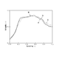
- FIG. 4 shows an example when the ore layer thickness ratio thus obtained fluctuates.
- Comparative Example 1 in Table 1 the surface profile of the furnace interior is measured and the ore layer thickness ratio is calculated. Is observed and the operation is continued as it is. This operation had a high ventilation resistance index as shown in Table 1, and the air permeability in the blast furnace was poor.
- the tilt angle of the swivel chute when charging coke is adjusted to the furnace wall side (the tilt angle with respect to the center axis of the furnace is changed from 25 ° to 50 °)
- the ore layer thickness ratio on the furnace wall side as a whole decreased as shown in FIG. 5 (Comparative Example 2).
- Table 1 although the air flow resistance index was reduced, the hot metal temperature was lowered, and as a result, the reducing material ratio, which is the sum of the coke ratio and pulverized coal ratio, was increased. Note that the turning speed of the turning chute and the feed rate of the raw material were kept constant during this operation.
- the tilt angle of the turning chute is adjusted to the wall side only when the coke is charged to the north side in turning of the turning chute (furnace of the furnace)
- the inclination angle with respect to the central axis was changed from 25 ° to 50 °
- only the ore layer thickness ratio of the furnace wall on the north side could be reduced (Invention Example 1). That is, as shown in FIG. 6, the deviation of the ore layer thickness ratio in the furnace circumferential direction was reduced, and as shown in Table 1, the airflow resistance index was reduced from that in Comparative Example 1, and the hot metal temperature was also increased. As a result, the coke ratio could be reduced.
- the ventilation resistance index is higher than that of Comparative Example 2, it is a preferable operation as a whole. This is because, in Comparative Example 2, the ore layer thickness ratio near the furnace wall in the entire blast furnace decreased, so coke near the furnace wall increased, gas flowed near the furnace wall, and gas was not effectively used. As a result, although the ventilation resistance index was low, it is considered that the overall operation results were poor.
- Example 2 when the coke is charged, the coke supply speed to the turning chute is constant, and the turning speed of the turning chute is reduced in a specific direction in the blast furnace, so that the coke is deposited in the specific direction. I was able to increase the amount. On the other hand, the coke supply speed can be increased so that the amount of coke falling in the specific direction increases with the turning speed of the turning chute constant. Even when the coke supply speed in a specific direction was increased while keeping the turning speed of the turning chute constant, the same effect as in this example was obtained.
Landscapes
- Engineering & Computer Science (AREA)
- Chemical & Material Sciences (AREA)
- Mechanical Engineering (AREA)
- General Engineering & Computer Science (AREA)
- Manufacturing & Machinery (AREA)
- Materials Engineering (AREA)
- Metallurgy (AREA)
- Organic Chemistry (AREA)
- Remote Sensing (AREA)
- Radar, Positioning & Navigation (AREA)
- Physics & Mathematics (AREA)
- Electromagnetism (AREA)
- Computer Networks & Wireless Communication (AREA)
- General Physics & Mathematics (AREA)
- Manufacture Of Iron (AREA)
- Blast Furnaces (AREA)
Abstract
Priority Applications (7)
| Application Number | Priority Date | Filing Date | Title |
|---|---|---|---|
| JP2020510824A JP7176560B2 (ja) | 2018-03-28 | 2019-03-25 | 高炉操業方法 |
| CN201980020735.1A CN111886348A (zh) | 2018-03-28 | 2019-03-25 | 高炉设备及高炉的作业方法 |
| EP19775560.6A EP3778928B1 (fr) | 2018-03-28 | 2019-03-25 | Procédé de chargement d'un haut fourneau |
| KR1020207030581A KR102472919B1 (ko) | 2018-03-28 | 2019-03-25 | 고로의 조업 방법 |
| RU2020134028A RU2753936C1 (ru) | 2018-03-28 | 2019-03-25 | Устройство для доменной печи и способ выполнения операции для доменной печи |
| US17/040,537 US11940215B2 (en) | 2018-03-28 | 2019-03-25 | Blast furnace apparatus and operation method for blast furnace |
| BR112020019405-0A BR112020019405B1 (pt) | 2018-03-28 | 2019-03-25 | Método de operação para um alto-forno usando um aparelho de altoforno |
Applications Claiming Priority (2)
| Application Number | Priority Date | Filing Date | Title |
|---|---|---|---|
| JP2018-062433 | 2018-03-28 | ||
| JP2018062433 | 2018-03-28 |
Publications (1)
| Publication Number | Publication Date |
|---|---|
| WO2019189025A1 true WO2019189025A1 (fr) | 2019-10-03 |
Family
ID=68060110
Family Applications (1)
| Application Number | Title | Priority Date | Filing Date |
|---|---|---|---|
| PCT/JP2019/012586 Ceased WO2019189025A1 (fr) | 2018-03-28 | 2019-03-25 | Installation de haut fourneau et procédé de fonctionnement pour haut fourneau |
Country Status (8)
| Country | Link |
|---|---|
| US (1) | US11940215B2 (fr) |
| EP (1) | EP3778928B1 (fr) |
| JP (1) | JP7176560B2 (fr) |
| KR (1) | KR102472919B1 (fr) |
| CN (1) | CN111886348A (fr) |
| BR (1) | BR112020019405B1 (fr) |
| RU (1) | RU2753936C1 (fr) |
| WO (1) | WO2019189025A1 (fr) |
Cited By (7)
| Publication number | Priority date | Publication date | Assignee | Title |
|---|---|---|---|---|
| JP2021113340A (ja) * | 2020-01-17 | 2021-08-05 | 日本製鉄株式会社 | 高炉の操業方法 |
| JP2021161505A (ja) * | 2020-04-01 | 2021-10-11 | 日本製鉄株式会社 | 高炉原料の装入決定方法、装入方法決定装置および装入方法決定プログラム |
| JP2021167453A (ja) * | 2020-04-13 | 2021-10-21 | 日本製鉄株式会社 | 高炉の操業方法、微粉炭吹込制御装置、微粉炭吹込制御プログラム |
| JP2022126369A (ja) * | 2021-02-18 | 2022-08-30 | 日本製鉄株式会社 | 高炉原料装入制御方法、高炉原料装入制御装置、高炉原料装入制御プログラム |
| JP2023046165A (ja) * | 2021-09-22 | 2023-04-03 | 日本製鉄株式会社 | 高炉原料の装入決定方法、装入方法決定装置および装入方法決定プログラム |
| JP2023046166A (ja) * | 2021-09-22 | 2023-04-03 | 日本製鉄株式会社 | 高炉原料の装入決定方法、装入方法決定装置および装入方法決定プログラム |
| JP7294741B1 (ja) | 2023-04-14 | 2023-06-20 | 株式会社Wadeco | 装入物の表面プロフィール検出装置及び操業方法 |
Families Citing this family (5)
| Publication number | Priority date | Publication date | Assignee | Title |
|---|---|---|---|---|
| CN113139275B (zh) * | 2021-03-22 | 2022-08-19 | 浙江大学 | 一种基于多层矿焦比分布模型的高炉炉喉温度估计方法 |
| CN113174451A (zh) * | 2021-04-15 | 2021-07-27 | 鞍钢股份有限公司 | 高炉炉料预装分布控制方法 |
| CN113609936B (zh) * | 2021-07-22 | 2024-03-15 | 武汉钢铁有限公司 | 高炉上部炉料径向下降速度分布的确定方法 |
| CN115874003B (zh) * | 2022-10-19 | 2025-02-18 | 北京首钢股份有限公司 | 一种溜槽倾角的测量方法 |
| CN118563032B (zh) * | 2024-05-21 | 2025-06-06 | 江苏省沙钢钢铁研究院有限公司 | 基于高炉料面扫描的高炉冶炼速度均匀性评价方法 |
Citations (5)
| Publication number | Priority date | Publication date | Assignee | Title |
|---|---|---|---|---|
| JPH02190409A (ja) * | 1989-01-17 | 1990-07-26 | Sumitomo Metal Ind Ltd | 高炉の原料装入方法 |
| JPH0421707A (ja) * | 1990-05-16 | 1992-01-24 | Kawasaki Steel Corp | 高炉への原料装入方法 |
| JPH0611328A (ja) * | 1992-03-23 | 1994-01-21 | Sumitomo Metal Ind Ltd | 竪型炉の装入物プロフィール測定方法および測定装置 |
| WO2015133005A1 (fr) | 2014-03-04 | 2015-09-11 | 株式会社ワイヤーデバイス | Procédé pour charger et déposer un matériau de charge dans un four à cuve, dispositif de détection de surface de matériau de charge et procédé de fonctionnement d'un four à cuve |
| JP2017095761A (ja) | 2015-11-24 | 2017-06-01 | Jfeスチール株式会社 | 高炉における装入物分布制御方法 |
Family Cites Families (17)
| Publication number | Priority date | Publication date | Assignee | Title |
|---|---|---|---|---|
| JPS537505A (en) | 1976-07-09 | 1978-01-24 | Nippon Steel Corp | Operating process of blast furnace |
| SE421832B (sv) | 1979-04-18 | 1982-02-01 | Pharos Ab | Anordning for att registrera topografin hos den chargerade massan i en masugn |
| US4463437A (en) * | 1981-04-27 | 1984-07-31 | Bethlehem Steel Corp. | Furnace burden thermographic method and apparatus |
| JPS58123808A (ja) * | 1982-01-14 | 1983-07-23 | Sumitomo Metal Ind Ltd | 高炉の原料装入方法 |
| US4747062A (en) * | 1984-12-24 | 1988-05-24 | Amoco Corporation | Method and apparatus for detecting the level of a liquid in a tank |
| RU2089617C1 (ru) | 1994-11-08 | 1997-09-10 | Государственное научно-производственное предприятие "Исток" | Способ определения параметров засыпи шихты в доменной печи |
| FI98659C (fi) | 1995-09-27 | 1997-07-25 | Henrik Saxen | Menetelmä masuunin kuilussa vallitsevan kaasuvuojakauman määrittämiseksi |
| CN101492750B (zh) | 2008-12-30 | 2010-12-29 | 北京科技大学 | 基于工业相控阵雷达的高炉料面测量与控制系统 |
| CN102732659B (zh) | 2011-04-11 | 2014-01-08 | 宝山钢铁股份有限公司 | 高炉布料的料面形状控制方法及控制系统 |
| CN103160628A (zh) * | 2011-12-12 | 2013-06-19 | 上海梅山钢铁股份有限公司 | 一种高炉布料溜槽倾动的变频控制方法 |
| DE102014200928B4 (de) * | 2014-01-20 | 2025-06-26 | Tmt Tapping Measuring Technology Sàrl | Vorrichtung zur Bestimmung der Topographie der Mölleroberfläche in einem Schachtofen |
| CN104531924B (zh) * | 2014-12-18 | 2016-10-19 | 东北大学 | 一种高炉炉料分布实时预报系统及方法 |
| JP6183412B2 (ja) | 2015-05-28 | 2017-08-23 | Jfeスチール株式会社 | 高炉への原料装入装置 |
| WO2017022818A1 (fr) | 2015-08-04 | 2017-02-09 | 株式会社ワイヤーデバイス | Dispositif de détection de surface et procédé de chargement d'un matériau chargé dans un haut fourneau et procédé de fonctionnement d'un haut fourneau |
| JP6770738B2 (ja) * | 2016-09-23 | 2020-10-21 | 株式会社Wadeco | 高炉用表面検出装置 |
| WO2019189034A1 (fr) * | 2018-03-28 | 2019-10-03 | Jfeスチール株式会社 | Installation de haut-fourneau et procédé d'exploitation de haut-fourneau |
| CN108486300B (zh) * | 2018-04-04 | 2020-02-21 | 秦皇岛秦冶重工有限公司 | 布料器倾动机构及该机构的控制方法 |
-
2019
- 2019-03-25 WO PCT/JP2019/012586 patent/WO2019189025A1/fr not_active Ceased
- 2019-03-25 BR BR112020019405-0A patent/BR112020019405B1/pt active IP Right Grant
- 2019-03-25 CN CN201980020735.1A patent/CN111886348A/zh active Pending
- 2019-03-25 KR KR1020207030581A patent/KR102472919B1/ko active Active
- 2019-03-25 RU RU2020134028A patent/RU2753936C1/ru active
- 2019-03-25 JP JP2020510824A patent/JP7176560B2/ja active Active
- 2019-03-25 US US17/040,537 patent/US11940215B2/en active Active
- 2019-03-25 EP EP19775560.6A patent/EP3778928B1/fr active Active
Patent Citations (5)
| Publication number | Priority date | Publication date | Assignee | Title |
|---|---|---|---|---|
| JPH02190409A (ja) * | 1989-01-17 | 1990-07-26 | Sumitomo Metal Ind Ltd | 高炉の原料装入方法 |
| JPH0421707A (ja) * | 1990-05-16 | 1992-01-24 | Kawasaki Steel Corp | 高炉への原料装入方法 |
| JPH0611328A (ja) * | 1992-03-23 | 1994-01-21 | Sumitomo Metal Ind Ltd | 竪型炉の装入物プロフィール測定方法および測定装置 |
| WO2015133005A1 (fr) | 2014-03-04 | 2015-09-11 | 株式会社ワイヤーデバイス | Procédé pour charger et déposer un matériau de charge dans un four à cuve, dispositif de détection de surface de matériau de charge et procédé de fonctionnement d'un four à cuve |
| JP2017095761A (ja) | 2015-11-24 | 2017-06-01 | Jfeスチール株式会社 | 高炉における装入物分布制御方法 |
Non-Patent Citations (1)
| Title |
|---|
| See also references of EP3778928A4 |
Cited By (15)
| Publication number | Priority date | Publication date | Assignee | Title |
|---|---|---|---|---|
| JP7393636B2 (ja) | 2020-01-17 | 2023-12-07 | 日本製鉄株式会社 | 高炉の操業方法 |
| JP2021113340A (ja) * | 2020-01-17 | 2021-08-05 | 日本製鉄株式会社 | 高炉の操業方法 |
| JP2021161505A (ja) * | 2020-04-01 | 2021-10-11 | 日本製鉄株式会社 | 高炉原料の装入決定方法、装入方法決定装置および装入方法決定プログラム |
| JP7453527B2 (ja) | 2020-04-01 | 2024-03-21 | 日本製鉄株式会社 | 高炉原料の装入決定方法、装入方法決定装置および装入方法決定プログラム |
| JP2021167453A (ja) * | 2020-04-13 | 2021-10-21 | 日本製鉄株式会社 | 高炉の操業方法、微粉炭吹込制御装置、微粉炭吹込制御プログラム |
| JP7436831B2 (ja) | 2020-04-13 | 2024-02-22 | 日本製鉄株式会社 | 高炉の操業方法、微粉炭吹込制御装置、微粉炭吹込制御プログラム |
| JP2022126369A (ja) * | 2021-02-18 | 2022-08-30 | 日本製鉄株式会社 | 高炉原料装入制御方法、高炉原料装入制御装置、高炉原料装入制御プログラム |
| JP7610107B2 (ja) | 2021-02-18 | 2025-01-08 | 日本製鉄株式会社 | 高炉原料装入制御方法、高炉原料装入制御装置、高炉原料装入制御プログラム |
| JP2023046166A (ja) * | 2021-09-22 | 2023-04-03 | 日本製鉄株式会社 | 高炉原料の装入決定方法、装入方法決定装置および装入方法決定プログラム |
| JP2023046165A (ja) * | 2021-09-22 | 2023-04-03 | 日本製鉄株式会社 | 高炉原料の装入決定方法、装入方法決定装置および装入方法決定プログラム |
| JP7640855B2 (ja) | 2021-09-22 | 2025-03-06 | 日本製鉄株式会社 | 高炉原料の装入決定方法、装入方法決定装置および装入方法決定プログラム |
| JP7688266B2 (ja) | 2021-09-22 | 2025-06-04 | 日本製鉄株式会社 | 高炉原料の装入決定方法、装入方法決定装置および装入方法決定プログラム |
| JP7294741B1 (ja) | 2023-04-14 | 2023-06-20 | 株式会社Wadeco | 装入物の表面プロフィール検出装置及び操業方法 |
| WO2024214312A1 (fr) * | 2023-04-14 | 2024-10-17 | 株式会社Wadeco | Dispositif de détection de profil de surface de matériau de charge et procédé de fonctionnement |
| JP2024152394A (ja) * | 2023-04-14 | 2024-10-25 | 株式会社Wadeco | 装入物の表面プロフィール検出装置及び操業方法 |
Also Published As
| Publication number | Publication date |
|---|---|
| EP3778928A4 (fr) | 2021-02-17 |
| US11940215B2 (en) | 2024-03-26 |
| BR112020019405B1 (pt) | 2023-12-26 |
| EP3778928B1 (fr) | 2022-02-23 |
| JP7176560B2 (ja) | 2022-11-22 |
| JPWO2019189025A1 (ja) | 2021-03-25 |
| EP3778928A1 (fr) | 2021-02-17 |
| KR20200133382A (ko) | 2020-11-27 |
| KR102472919B1 (ko) | 2022-11-30 |
| CN111886348A (zh) | 2020-11-03 |
| RU2753936C1 (ru) | 2021-08-24 |
| BR112020019405A2 (pt) | 2021-01-05 |
| US20210041172A1 (en) | 2021-02-11 |
Similar Documents
| Publication | Publication Date | Title |
|---|---|---|
| WO2019189025A1 (fr) | Installation de haut fourneau et procédé de fonctionnement pour haut fourneau | |
| CN111886347B (zh) | 高炉设备以及高炉的操作方法 | |
| JP6447470B2 (ja) | 高炉における装入物分布制御方法 | |
| JP6327383B1 (ja) | 高炉における装入物分布制御方法 | |
| JP4383313B2 (ja) | 高炉内装入物の表面形状測定方法および測定装置 | |
| JP6033690B2 (ja) | 高炉内装入物のプロフィル測定装置 | |
| EP3896177B1 (fr) | Procédé d'enfournement de matière première dans un haut fourneau sans cloche, et procédé d'exploitation de haut fourneau | |
| JP3514120B2 (ja) | 高炉炉頂装入物の分布制御方法 | |
| JP2021113341A (ja) | 高炉の操業方法 | |
| JP2017020078A (ja) | 高炉 | |
| JPH08350Y2 (ja) | ホツパ−からの時系列排出粒度特性の調整装置 | |
| JP2001049312A (ja) | ベルレス高炉における原料装入方法 | |
| JPH01259109A (ja) | ベル式高炉の原料装入方法 | |
| JP2023057594A (ja) | 高炉の操業方法、装入方法制御装置及び装入方法制御プログラム | |
| JP2021175822A (ja) | 中心コークスの投入方法 | |
| JPH08246011A (ja) | 高炉の原料装入方法およびその装置 | |
| JPH11236610A (ja) | ベル式高炉の操業方法 | |
| JPH06271907A (ja) | ベルレス高炉における原料装入方法 | |
| JPS599109A (ja) | 高炉炉内ガス分布制御方法 |
Legal Events
| Date | Code | Title | Description |
|---|---|---|---|
| 121 | Ep: the epo has been informed by wipo that ep was designated in this application |
Ref document number: 19775560 Country of ref document: EP Kind code of ref document: A1 |
|
| ENP | Entry into the national phase |
Ref document number: 2020510824 Country of ref document: JP Kind code of ref document: A |
|
| NENP | Non-entry into the national phase |
Ref country code: DE |
|
| ENP | Entry into the national phase |
Ref document number: 20207030581 Country of ref document: KR Kind code of ref document: A |
|
| REG | Reference to national code |
Ref country code: BR Ref legal event code: B01A Ref document number: 112020019405 Country of ref document: BR |
|
| ENP | Entry into the national phase |
Ref document number: 2019775560 Country of ref document: EP Effective date: 20201028 |
|
| ENP | Entry into the national phase |
Ref document number: 112020019405 Country of ref document: BR Kind code of ref document: A2 Effective date: 20200924 |