WO2019189689A1 - Manchon et procédé d'installation de celui-ci - Google Patents
Manchon et procédé d'installation de celui-ci Download PDFInfo
- Publication number
- WO2019189689A1 WO2019189689A1 PCT/JP2019/013867 JP2019013867W WO2019189689A1 WO 2019189689 A1 WO2019189689 A1 WO 2019189689A1 JP 2019013867 W JP2019013867 W JP 2019013867W WO 2019189689 A1 WO2019189689 A1 WO 2019189689A1
- Authority
- WO
- WIPO (PCT)
- Prior art keywords
- sleeve
- cap
- main body
- locking bar
- attached
- Prior art date
- Legal status (The legal status is an assumption and is not a legal conclusion. Google has not performed a legal analysis and makes no representation as to the accuracy of the status listed.)
- Ceased
Links
Images



Classifications
-
- E—FIXED CONSTRUCTIONS
- E04—BUILDING
- E04G—SCAFFOLDING; FORMS; SHUTTERING; BUILDING IMPLEMENTS OR AIDS, OR THEIR USE; HANDLING BUILDING MATERIALS ON THE SITE; REPAIRING, BREAKING-UP OR OTHER WORK ON EXISTING BUILDINGS
- E04G15/00—Forms or shutterings for making openings, cavities, slits, or channels
- E04G15/06—Forms or shutterings for making openings, cavities, slits, or channels for cavities or channels in walls of floors, e.g. for making chimneys
Definitions
- the present invention relates to a sleeve for forming a through-hole through which various pipes and wirings are inserted in a concrete structure such as a wall or a beam, and a method for installing the sleeve, and more specifically, the workability and distinguishability of the sleeve. It is about improvement.
- through holes are formed in parts such as walls and beams to pass various pipes and wiring (cables).
- a through hole is usually formed by attaching a sleeve (sheath tube) between the inner surfaces of a mold having a predetermined width or length, and then placing concrete. Since the length of the through hole is not necessarily constant, an expandable and contractible sleeve has been proposed for the purpose of accommodating the length of the through hole by making the length of the sleeve adjustable. There has also been proposed a technique aimed at efficiently performing a sleeve installation operation by attaching a holder for fixing the sleeve to the inner surface of the mold in advance.
- Patent Document 1 includes an outer sleeve and an inner sleeve that can be inserted into the outer sleeve, and includes a locking unit that prevents the outer sleeve and the inner sleeve from being detached when extended.
- a slide sleeve for building work is disclosed.
- Patent Document 2 a plurality of protruding pieces provided with nail holes are provided on the outer periphery of a receiving body that is formed with an arc-shaped rising piece that is open on the sleeve, and the sleeve is provided on the inner periphery.
- a sleeve receiver for equipment construction which is provided with anchor pieces for preventing the hooks from coming off.
- the present inventor has proposed a concrete through-hole sleeve that is more excellent in workability, has a better concrete structure finish, and is suitable for preventing concrete from entering the sleeve.
- Patent No. 5917155 a pair of fixing holders, one end of which is in contact with the inner surface of the formwork, inside both ends of the sleeve main body composed of one or more inner cylinders and outer cylinders, which overlap each other so as to expand and contract in the axial direction.
- the present invention focuses on the above points, and an object thereof is to provide a sleeve excellent in workability that can be installed in a short time. Another purpose is to conveniently identify the use of the sleeve.
- the sleeve of the present invention is a sleeve for forming a through-hole in a concrete structure, and is composed of a sleeve body that can be expanded and contracted, and caps provided at both ends of the sleeve body.
- An engaging means is provided between the cap and a peripheral surface, and an detaching means for opening the engaging means is provided on an end surface of the cap.
- a sleeve according to another invention is a sleeve for forming a through-hole in a concrete structure, and is an extendable sleeve main body, caps provided at both ends thereof, and a locking bar for attaching the cap to a formwork And an engaging means is provided between the end of the sleeve main body and the peripheral surface of the cap, and a removing means for releasing the engaging means is provided on the end surface of the cap. It is characterized by that.
- a cap is attached to the formwork via a locking bar.
- the sleeve main body is constituted by an outer sleeve and an inner sleeve, and has a structure that expands and contracts by overlapping both the sleeves.
- the diameter of the end portion to which the cap of the outer sleeve is attached is the same as the diameter of the end portion to which the cap of the inner sleeve is attached.
- the engaging means is a concave shape or opening provided on the inner side of the end portion of the sleeve main body, and a protrusion provided on the peripheral surface of the cap.
- a nail piece for hitting a nail can be detachably attached to the outer end of the sleeve body.
- the cap is formed with an engaging portion that slides and engages with the locking bar, and the engaging portion is arranged in a radial direction of the end opening of the cap. It is formed so that it may pass.
- the sleeve main body is provided with a display indicating a work direction or a work procedure.
- the sleeve for floors of the present invention is a sleeve for forming a through hole in the floor surface of a concrete structure, and is composed of an extendable sleeve body and caps provided at both ends thereof.
- the cap is provided with an engaging means between the peripheral surface and the end of the sleeve body, and a removing means for releasing the engaging means is provided on the end face. Is provided with an identification tag in which information indicating the use of the sleeve is recorded.
- a floor sleeve according to another invention is a sleeve for forming a through-hole in a floor surface of a concrete structure, and is composed of an extendable sleeve body and caps provided at both ends thereof.
- the cap on the side is provided with an engaging means between the peripheral surface and the end of the sleeve body, and a removing means for releasing the engaging means is provided on the end face.
- the cap is characterized in that the periphery contacts the sleeve body with a tapered surface.
- a stopper with which the lower end of the cap abuts is provided inside the sleeve body.
- the cap may be transparent or translucent so that light incident on the sleeve body is transmitted to the floor surface.
- the cap is provided with fluorescence or phosphorescence.
- an O-ring for maintaining airtightness is interposed between the sleeve body and the cap.
- the cap surface is provided with a display indicating the use or type of the sleeve.
- a slip stopper is provided on the surface of the cap.
- the sleeve installation method of the present invention includes a step of attaching a laser marking device to a locking bar first attached to a mold frame among the locking bars, and performing marking with the attached laser marking device.
- the method includes a step of determining the mounting position of the other locking bar with respect to the frame, and a step of mounting the other locking bar at the determined mounting position.
- the engagement means is provided between the end portion of the sleeve main body and the peripheral surface of the cap, and the removal means for opening the engagement means is provided on the end surface of the cap. It can be installed in a short time and has excellent workability. Moreover, since the identification tag and the coloring which show the use are given to the cap of the sleeve main body installed in a floor surface, the use of a sleeve can be identified easily.
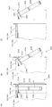
- Example 1 of this invention It is a perspective view which shows the whole structure of Example 1 of this invention. It is a figure which shows the effect
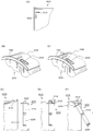
- FIG. It is a figure which shows the construction procedure of the sleeve of the said Example 1.
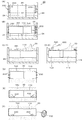
- FIG. It is a perspective view which shows the whole structure of Example 2 of this invention. It is a figure which shows Example 3 of this invention. It is a perspective view which shows the whole structure of Example 4 of this invention.
- FIG. It is a figure which shows the construction procedure by the said laser marking device.
- FIG. It is a figure which shows Example 5 of this invention. It is a figure which shows Example 6 of this invention.
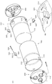
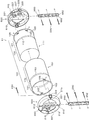
- FIG. 1 shows the entire sleeve 10 of the present embodiment, which is composed of a sleeve main body 100 and caps 200 at both ends thereof.
- the sleeve body 100 includes an inner sleeve 110 and an outer sleeve 150.
- the inner sleeve 110 and the outer sleeve 150 have attachment regions 120 and 160 and overlapping regions 130 and 170, and a ring-like shape is formed at the boundary between them.
- Protrusions 112 and 152 are provided, respectively.
- the overlapping regions 130 and 170 have different diameters so that they overlap each other.
- the diameters of the attachment regions 120 and 160 may be different, but by using the same diameter, the same cap 200 can be used.
- the attachment regions 120 and 160 of the inner sleeve 110 and the outer sleeve 150 are formed with flanges 122 and 162 at the tips, and openings 124 and 164 are formed at appropriate intervals in the vicinity thereof.
- openings 124 and 164 are formed in the circumferential direction of the inner sleeve 110 and the outer sleeve 150 at positions that are equally spaced at an angle of 120 degrees.
- the inner sleeve 110 and the outer sleeve 150 are provided with indications MA to MD indicating work directions and work procedures.
- the arrow of the display MA and the number of the display MB indicate that the inner sleeve 110 and the outer sleeve 150 are first stretched.
- the arrow of the display MC and the number of the display MD indicate that the inner sleeve 110 and the outer sleeve 150 are rotated second.
- the cap 200 has a shape that fits inside the mounting regions 120 and 160 of the inner sleeve 110 and the outer sleeve 150 described above, and circular openings 212 are formed at equal intervals on the end surface 210.
- a slit-like opening 214 is formed from the opening 212 toward the circumferential surface.
- three sets of circular openings 212 and slit-like openings 214 are formed at equal intervals in the circumferential direction.
- a part of the peripheral surface 220 of the cap 200 is cut out to form a protrusion 222.
- the protrusions 222 are formed at positions corresponding to the slit-shaped openings 214, respectively.
- the protrusion 222 is formed by two protruding shapes, but may be one continuous protruding shape.
- Arms 224 are extended from the protrusions 222 on the inner side of the cap 200, and removal rings 226 are provided on these arms 224.
- the width of the arm 224 is adjusted so that it can pass through the slit-like opening 214, and the size of the removal ring 226 is adjusted so that it can pass through the circular opening 212. That is, the removal ring 226 can be pulled out from the circular opening 212 of the end surface 210, and when the removal ring 226 is pulled out, the protrusion 222 of the peripheral surface 220 is deformed inward.
- the protrusion 222 is fitted into the openings 124 and 164 of the inner sleeve 110 and the outer sleeve 150 described above in an assembled state. Then, as shown in FIG. 2B, when the removal ring 226 is pulled out from the inside of the sleeve to the circular opening 212, the protrusion 222 is drawn inward from the peripheral surface 220, and the engagement between the openings 124 and 164 and the protrusion 222 is performed. Is solved and opened.
- the end surface 210 of the cap 200 is provided with a plurality of nail holes 216 at appropriate positions for fixing the cap 200 to a formwork described later.
- the nail holes 216 are provided symmetrically at equal intervals in the circumferential direction.
- the cap 200 is attached by driving the nail 230 into the nail hole 216 described above at the installation site on the inner surface of the mold 24 facing each other.
- the bar arrangement 26 is formed into a mold. Drop into the frame 24.
- the sleeve body 100 is positioned so that both ends thereof face the cap 200, and the sleeves 110 and 150 are extended according to the directions and procedures indicated by the indications MA and MB. Then, the attachment regions 120 and 160 of the sleeves 110 and 150 are attached to the cap 200, respectively. Next, the sleeves 110 and 150 are rotated according to the directions and procedures indicated by the indications MC and MD so that the openings 124 and 164 fit into the protrusions 222 of the cap 200. As a result, the sleeve 10 is attached to the mold 24 as shown in FIG.
- the concrete 30 is placed in the mold 24. After the concrete 30 is cured, the mold 24 is removed as shown in FIG. Then, the nail 230 that has fixed the cap 200 is exposed. In this state, the work cannot be performed safely. Therefore, the nail 230 is pushed into the sleeve main body 100 as shown in FIG. When a finger is inserted into the removal ring 226 from the circular opening 212 of the cap 200 and the removal ring 226 is pulled out, as shown in FIG. The caps 200 can be removed from the sleeve main body 100 as shown in FIGS. 2 (C) and 3 (F).
- the cap 200 is attached to the mold 24, and the protrusion 222 formed on the peripheral surface 220 is fitted into the openings 124 and 164 formed on the opening side of the sleeve main body 100, so that the sleeve main body can be touched with one touch.
- 100 can be attached to the cap 200, and the attaching operation of the sleeve 10 to the mold 24 can be performed in a short time.
- the indications MA to MD indicating the work direction and the work procedure are attached, the sleeve 10 can be attached even if it is not used.
- the nail 230 may be pushed into the sleeve, and cutting is not necessary.
- the protrusion 222 of the cap 200 is removed from the openings 124 and 164 of the sleeve body 100, and the cap 200 can be easily removed.
- the removed cap 200 can be reused and is economical.
- the application can be easily known by marking the outside of the cap 200 with different colors, patterns, characters, symbols, etc. for each application such as air conditioning, gas and water pipes, and electrical wiring. . The same applies to the embodiments described later.
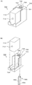
- FIG. 4 (A) shows the entire sleeve 300 of this embodiment
- FIG. 4 (B) shows the main part.
- columnar mounting guides 310 are provided at equal intervals on the opening side of the mounting regions 120 and 160 of the inner sleeve 110 and the outer sleeve 150.
- an attachment guide 310 is formed adjacent to the openings 124 and 164 that engage with the protrusions 222 of the cap 200.
- a fan-shaped nail piece 320 is detachably attached to these mounting guides 310.
- the nail piece 320 includes a fixing hole 322 into which the mounting guide 310 is inserted and fixed, and a nail hole 324 into which the nail is inserted.
- the sleeve body 100 may not be fixed well with the cap 200 alone.
- the nail piece 320 is attached so that the attachment guide 310 of each sleeve 110, 150 is inserted into the fixing hole 322 of the nail piece 320.
- the sleeve body 100 is fixed by inserting the nail 330 through the nail hole 324 of the nail piece 320 and driving it into the mold 24.
- the nail piece 320 is detachably attached to the opening side of each sleeve 110, 150. Therefore, the nail 330 is also used from the outside of the cap 200 as necessary.
- the main body 100 can be fixed, and the situation at the work site can be flexibly dealt with.
- FIG. 5A shows the opening 402 of the sleeve main body 400 of this embodiment, which is formed so that the width becomes narrower in the longitudinal direction (circumferential direction). Therefore, as shown in FIG. 5B, the protrusion 222 on the cap 200 side can easily enter the opening 402 near the center of the opening 402. Thereafter, in this embodiment, the sleeve body 400 is rotated in the circumferential direction. For example, when it is turned in the direction indicated by the arrow in FIG.
- the protrusion 222 bites into the narrow portion of the opening 402, and the protrusion 222 is firmly engaged with the opening 402.
- the cap 200 is rotated in the opposite direction by the removal ring 226 and then pulled.
- the narrow portion is provided in both the longitudinal direction (circumferential direction) of the opening 402, but may be provided only in one.
- a recessed portion 412 that is recessed from the inside to the outside is formed in the attachment region of the sleeve body 410.
- the openings 124, 164, and 402 of the above-described embodiment are shaped so as to cover from the outside of the sleeve body 410.
- the protrusion 222 of the cap 200 is fitted into the recess 412. As shown in FIG. By removing, the cap 200 can be removed from the sleeve body 410.
- the shape of the opening of the recess 412 may be a shape whose width becomes narrower in the longitudinal direction (circumferential direction) as shown in FIGS.
- the concrete 30 flows into the openings 124, 164 and 402, and the protrusions 222 are unlikely to come off from the openings 124, 164 and 402.
- the recess 412 is closed when viewed from the outside of the sleeve body 410, such inconvenience does not occur.
- FIG. 6 shows the entire sleeve 11 of this embodiment, which is composed of a sleeve body 101, caps 600 at both ends thereof, and a locking bar 650.
- the sleeve body 101 includes an inner sleeve 111 and an outer sleeve 151.
- the inner sleeve 111 and the outer sleeve 151 have attachment regions 121 and 161 and overlapping regions 130 and 170, and a ring-like shape is formed at the boundary between them.
- Protrusions 113 and 153 are provided, respectively.
- the overlapping regions 130 and 170 have different diameters in the same manner as in the above embodiment, and both overlap each other. Although the diameters of the attachment regions 121 and 161 may be different, the same cap 600 can be used by setting the diameters to the same.
- the flanges 123 and 163 are formed at the tips of the attachment regions 121 and 161 of the inner sleeve 111 and the outer sleeve 151, and a plurality of openings 125 and 165 are formed in the vicinity thereof.
- three openings 125 and 165 are formed in the circumferential direction of the inner sleeve 111 and the outer sleeve 151 in correspondence with positions of protrusions 223 of the cap 600 described later, not at equal intervals.
- the cap 600 has a shape that fits inside the mounting regions 121 and 161 of the inner sleeve 111 and the outer sleeve 151 described above, and an opening 213 is provided on the end surface.
- a slit-shaped opening 215 is formed from the opening 213 toward the outer peripheral direction. In the illustrated example, three sets of slit-like openings 215 are formed.
- a protrusion 223 is formed on the peripheral surface 221 of the cap 600 by cutting out a part thereof. The protrusions 223 are formed at positions corresponding to the slit-shaped openings 215, respectively. In the example shown in the figure, the protrusion 223 is formed by two protruding shapes, but may be one continuous protruding shape.
- the arms 225 are extended from the protrusions 223 on the inner side of the cap 600, and the removal rings 227 are provided on these arms 225.
- the width of the arm 225 is adjusted so that it can pass through the slit-shaped opening 215, and the removal ring 227 can pass through the opening 213. That is, the removal ring 227 can be pulled out from the opening 213, and when the removal ring 227 is pulled out, the protrusion 223 of the peripheral surface 221 is deformed inward.
- the basic operation of the projection 223, the arm 225, and the removal ring 227 is as shown in FIG. 2, and is the same as that of the above embodiment.
- an engaging portion 610 is formed in the opening 213 of the cap 600 so as to pass in the radial direction, and slides and engages with the locking bar 650.
- a concave rail 612 is formed in the engaging portion 610 in the longitudinal direction, and a convex rail 652 is formed in the locking bar 650 in the longitudinal direction.
- the shape of the unevenness may be reversed.
- the locking bar 650 is fixed to the mold 24 with a nail 230, and the concave rail 612 of the engaging portion 610 of the cap 600 slides and is inserted into the convex rail 652 of the locking bar 650. As a result, the concaves and convexes of both engage, and the cap 600 is attached to the locking bar 650.
- the engaging portion 610 of the cap 600 is provided with a stopper (not shown), so that the cap 600 is positioned and attached to the locking bar 650.
- the length of the locking bar 650 is set so that it fits within the engaging portion 610 of the cap 600.
- the cap 200 is fixed to the mold 24 with the nail 230.
- the locking bar 650 is first fixed to the mold 24 with the nail 230, and the cap 600 is attached to the locking bar 650. Is attached and fixed.
- the cap 600 may be fixed to the mold 24 using the nail 230.
- the engaging portion 610 is provided in the cap 600, the mounting positions of the protrusion 223, the arm 225, and the removal ring 227 described above are equally spaced in the circumferential direction of the cap 600. Absent.
- FIG. 4A shows a state where the laser marking device 700 is assembled
- FIG. 4B shows a state before the assembly.
- the laser marking device 700 is configured such that a laser oscillator 710 that outputs a cross-shaped laser beam is installed on an installation table 720.
- a commercially available laser oscillator 710 can be used.
- the installation base 720 is provided with a housing 724 for the laser oscillator 710 on the front side, and a level 722 on the upper surface side. A level 722 may be provided on the laser transmitter 710 side.
- Some commercially available laser marking devices are provided with a level, which may be used.
- An engaging portion 726 that engages with the above-described locking bar 650 is provided on the back side of the installation base 720.
- the engaging portion 726 is provided with a concave rail 728 that slides on the convex rail 652 of the locking bar 650 and engages with the concave and convex portions.
- the laser marking device 700 is provided on the locking bar 650. Can be attached.
- a stopper (not shown) is provided so that the laser beam output from the laser marking device 700 coincides with the longitudinal center of the locking bar 650.
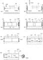
- FIG. 8 (A-1) and (B-1) are views of the mold 24 as viewed from above, and (A-2) and (B-2) are as viewed from the side. Further, the two locking bars 650 are distinguished from each other by attaching the symbols A and B. a. First, one locking bar 650A is positioned and fixed to the formwork 24 with the nail 230 by a method such as marking. b. Next, the locking bar 650B is attached to the laser marking device 700 and fixed at a position regulated by a stopper.
- the locking bar 650 ⁇ / b> B on the back surface of the laser marking device 700 is applied to the opposite side surface of the mold 24.
- the laser beam is output to irradiate the opposite locking bar 650A, and the position of the locking bar 650B in the vertical and horizontal directions is adjusted so that the laser beam hits the center. If necessary, the inclination of the locking bar 650B is adjusted with reference to the level 722.
- the locking bar 650B is fixed to the mold 24 with the nail 230. After fixing, the laser marking device 700 is slid and removed.
- the locking bar 650B can be attached to the mold 24 so that the center of the locking bar 650A coincides and faces the locking bar 650A.
- the cap 600 is each attached to the latching bar 650 attached to the formwork 24, as shown to the same figure (B-1) and (B-2).
- a locking bar 650A is attached by a nail 230 to one of the opposing inner surfaces of the mold 24, and then, as shown in FIG. Device 700 is used to attach the opposite locking bar 650B. Then, as shown in FIG. 9B, caps 600 are attached to the locking bars 650A and 650B, respectively.
- the inner sleeve 111 and the outer sleeve 151 are overlapped to shorten the sleeve main body 101 and are loaded into the reinforcing bar 26, and then the reinforcing bar 26 is dropped into the formwork 24. .
- the sleeve body 101 is positioned so that both ends thereof are opposed to the cap 600, and the sleeves 111 and 151 are extended and rotated so that the openings 125 and 165 fit into the protrusions 223 of the cap 600. . Thereby, as shown in FIG. 4D, the sleeve main body 101 is attached to the mold 24.
- the concrete 30 is placed in the mold 24, and after the curing, the mold 24 is removed. Then, the nail 230 that has fixed the locking bar 650 is exposed as shown in FIG. In this state, since the work cannot be performed safely, the nail 230 is pushed into the sleeve main body 101 as shown in FIG. Then, when a finger is inserted into the removal ring 227 from the circular opening 213 of the cap 600 and the removal ring 227 is pulled out, the protrusion 223 of the cap 600 comes out of the openings 125 and 165 of the sleeves 111 and 151, As shown in FIG. 4G, the cap 600 can be removed from the sleeve main body 101. At this time, the locking bar 650 is also removed at the same time while being accommodated in the engaging portion 610 of the cap 600.
- the nail driving operation can be easily performed.
- the work of attaching the sleeve 11 to the mold 24 can be performed in a short time. Removal of the cap 600 and the locking bar 650 is also easy.
- the removed cap 600 and the locking bar 650 can be reused and are economical.
- the cap 600 and locking bar 650 can be easily used by marking them with different colors, patterns, characters, symbols, etc. for each application, such as air conditioning, gas or water pipes, and electrical wiring. I can know.
- the sleeve 800 of the present embodiment includes a sleeve body 810 and caps 200 (600) and 820.
- a flange 812 is formed on the upper opening side over the entire circumference.
- the lower opening side is the same as in the above-described embodiment.
- a case 902 is provided on the lower side of the cap 820 so as to be detachable by fitting concaves and convexes, etc., and the identification tag 900 is accommodated in the case 902.
- the upper cap 820 has a shape in which the inner side is recessed by a recess 822, a peripheral surface 824, and a flange 826.
- the peripheral surface 824 faces the inner peripheral surface of the sleeve body 810
- the flange 826 faces the flange 812 of the sleeve body 810 and the O-ring 830.
- a cap 820 is placed over the upper opening as shown in FIG. At this time, water-tightness or airtightness is ensured by inserting an O-ring 830 between the flanges 812 and 826.
- the concrete 920 is placed in this state, the concrete 920 is covered with the cap 820 as shown in FIG. For this reason, it cannot be determined from which position the sleeve 800 is located.
- the tag tag 910 is used to detect the identification tag 900.
- the identification tag 900 for example, an RFID tag is used.
- information indicating the use or type of the sleeve 800 to which the identification tag 900 is attached is recorded.
- information indicating air conditioning, gas and water pipes, electrical wiring, and the like is recorded. Therefore, by reading the information of the identification tag 900 by the tag scanner 910, a, The sleeve 800 hidden by the concrete 920 can be found. b, it is possible to identify the intended use of the found sleeve 800;
- the surface concrete 922 is crushed and the cap 820 is removed.
- the cap 200 (600) on the opposite side of the sleeve 800 is also removed in the same manner as in the above-described embodiment.
- the removed caps 200 (600) and 820 can be reused. Even if the cap 820 is damaged, the case 902 can be removed and the identification tag 900 can be taken out and reused.
- Embodiment 6 of the present invention will be described with reference to FIG.
- the floor sleeve 801 of the present embodiment is constituted by a sleeve body 811 and caps 200 (600) and 821, as shown in a longitudinal section in FIG.
- the cap 200 (600) is attached to the lower opening side of the sleeve body 811 in the same manner as the above-described embodiment, and the cap 821 is attached to the upper opening side.
- the cap 821 serves as a lid for the sleeve body 811 and a so-called curing lid.
- the sleeve main body 811 includes a lower outer sleeve 811A and an upper inner sleeve 811B.
- a rubber band 811C for fixing is provided so that the inner sleeve 811B does not enter the outer sleeve 811A.
- a stopper 811D for positioning by contacting the lower end of the cap 821 is provided on the inner side of the inner sleeve 811B, and a tapered flange 813 is formed on the entire upper side.
- the cap 821 has a cylindrical shape that enters the inner sleeve 811B on the lower side, and is provided with a taper diameter-expanding surface 827 that abuts on the taper flange 813 on the upper side.
- O-rings 831A and 831B are provided between the cylindrical portion of the cap 821 and the inner sleeve 811B to ensure water-tightness or airtightness.
- an O-ring may be provided on a surface where the tapered flange 813 and the tapered enlarged diameter surface 827 are in contact with each other.
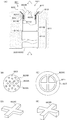
- the surface 823 of the cap 821 is provided with a non-slip 823A as shown in FIG. 5B, and a removal knob or handle 823B is provided at the center.
- a reinforcing beam 823C is provided on the back side (inside) of the cap 821, as shown in FIG. If only the beam 823C is shown, it becomes as shown in FIG.
- FIG. 5E shows a beam 823D having another shape.
- the cap 821 of the present embodiment has a taper structure with the above-described taper flange 813 and the taper enlarged diameter surface 827, so that the upper surface of the cap 821 is flush with the upper end of the inner sleeve 811B so that no step is generated. Become.
- the strength is designed not to be damaged by the beams 823C or 823D.
- the O-rings 831A and 831B ensure water-tightness or airtightness into the sleeve main body 811.
- a dish lid is simply placed on the top of the sleeve, it does not have a water stop function, and concrete is placed, concrete is poured, the lid is removed, and the lid is made of wood or plastic.
- the curing lid since a slight step is generated, the operator needs to pay attention to the whispering.
- the curing lid since the curing lid is also used, it is not necessary to replace the lid, and even if a working vehicle or the like is placed, it can withstand heavy pressure and work can be performed on the floor surface.
- the cap 821 transparent (translucent), light from under the floor can leak onto the floor (see arrow in FIG. 11 (A)).
- the cap 821 is made using fluorescent paint or phosphorescent paint. By adding fluorescence and phosphorescence to 821, the position can be known even at night. As a result, the position of the floor sleeve 801 can be easily known, and the cap 821 is displayed with different colors, patterns, characters, symbols, etc. for each application such as air conditioning, gas or water piping, and electrical wiring. By attaching it, it is possible to easily know the application, so that workability is improved.
- this invention is not limited to the Example mentioned above, A various change can be added in the range which does not deviate from the summary of this invention.
- the following are also included.
- the shapes and dimensions shown in the above-described embodiments are examples, and can be appropriately changed according to the shape and dimensions of the through-holes to be formed.
- three sets of protrusions, arms, and removal rings are provided, but the number may be increased or decreased as necessary.
- the intervals in the circumferential direction are not necessarily equal intervals, and may be appropriate intervals.
- (2) The above embodiments may be combined. For example, the display indicating the work direction or work procedure shown in FIG. 1 is applied to the example shown in FIGS. 4 to 6, the identification tag of FIG.
- the materials shown in the above embodiment are also examples, and may be appropriately changed depending on the application and installation location as long as the same effects are obtained.
- the sleeve cap provided on the floor uses an elastic material that easily transmits vibration, and even if the cap is hidden by concrete, the position of the cap can be found from vibration by hitting the floor with a hammer. There is an advantage that it is easy.
- the cap color is different depending on the application or type, the work can be performed smoothly even after the cap is attached to the sleeve.
- the structure of the fan-shaped nail piece 320 shown in FIG. 4 and the attachment structure to the attachment guide 310 are examples, and various structures may be used. Further, the angle between the fixing hole 322 and the nail hole 324 of the nail piece 320 may be set as appropriate, or ones having different angles may be prepared.
- As the expansion / contraction structure of the sleeve main body various structures such as the background art described above may be used in addition to the above-described embodiment.
- the through-hole formed by using the sleeve of the present invention is preferably applied to a beam, a wall, a floor, etc., but is not limited to this, and other known various concrete structures In general, the present invention is applicable.
- the engagement means is provided between the end portion of the sleeve main body and the peripheral surface of the cap, and the removal means for opening the engagement means is provided on the end surface of the cap. It can be installed in a short time and has excellent workability.
- the cap of the sleeve body installed on the floor is given an identification tag indicating its use and coloring, the use of the sleeve can be easily identified, and through holes for piping in buildings are formed. It is suitable for.
Landscapes
- Engineering & Computer Science (AREA)
- Architecture (AREA)
- Mechanical Engineering (AREA)
- Civil Engineering (AREA)
- Structural Engineering (AREA)
- Forms Removed On Construction Sites Or Auxiliary Members Thereof (AREA)
Abstract
La présente invention aborde le problème de la réalisation d'un manchon qui peut être installé en un temps court et qui présente une exceptionnelle aptitude au façonnage. La solution selon l'invention porte sur des capuchons (200) qui sont fixés à un moule (24), et des parties saillantes (222) formées sur les surfaces circonférentielles (220) des capuchons (200) sont ajustées dans des ouvertures (124, 164) formées sur le côté d'ouverture d'un corps de manchon (100). Le corps de manchon (100) peut être fixé aux capuchons (200) en une seule action, et le travail de fixation d'un manchon (10) au moule (24) peut être réalisé en un temps court. Après que le moule (24) a été retiré, les parties saillantes (222) des capuchons (200) sortent par une simple extraction de bagues d'extraction (226) des capuchons (200), et les capuchons (200) peuvent être retirés facilement.
Priority Applications (1)
| Application Number | Priority Date | Filing Date | Title |
|---|---|---|---|
| JP2020511049A JP7323110B2 (ja) | 2018-03-30 | 2019-03-28 | スリーブ及びその設置方法 |
Applications Claiming Priority (2)
| Application Number | Priority Date | Filing Date | Title |
|---|---|---|---|
| JP2018-066544 | 2018-03-30 | ||
| JP2018066544 | 2018-03-30 |
Publications (1)
| Publication Number | Publication Date |
|---|---|
| WO2019189689A1 true WO2019189689A1 (fr) | 2019-10-03 |
Family
ID=68061938
Family Applications (1)
| Application Number | Title | Priority Date | Filing Date |
|---|---|---|---|
| PCT/JP2019/013867 Ceased WO2019189689A1 (fr) | 2018-03-30 | 2019-03-28 | Manchon et procédé d'installation de celui-ci |
Country Status (2)
| Country | Link |
|---|---|
| JP (1) | JP7323110B2 (fr) |
| WO (1) | WO2019189689A1 (fr) |
Cited By (2)
| Publication number | Priority date | Publication date | Assignee | Title |
|---|---|---|---|---|
| JP2020200696A (ja) * | 2019-06-12 | 2020-12-17 | 日立Geニュークリア・エナジー株式会社 | 構造体の施工方法および埋設配管用の閉塞プラグ |
| JP2021185287A (ja) * | 2020-05-24 | 2021-12-09 | 博満 安徳 | スリーブ,キャップ,スリーブの設置方法 |
Citations (10)
| Publication number | Priority date | Publication date | Assignee | Title |
|---|---|---|---|---|
| JPS57123370A (en) * | 1981-01-21 | 1982-07-31 | Kojima Seisakusho Kk | Installation of piping material for body of building |
| JPS58168642U (ja) * | 1982-05-07 | 1983-11-10 | 有限会社パテント・リミテイツド | 蓋付きスリ−ブ |
| JPS6051246U (ja) * | 1983-09-14 | 1985-04-10 | 高砂熱学工業株式会社 | コンクリ−トスラブ打設用ボイドの蓋 |
| JPS63165623A (ja) * | 1986-12-25 | 1988-07-08 | 古沢 悌 | コンクリ−ト構造物の貫通孔形成方法及び貫通孔形成用器具 |
| JPH0439483A (ja) * | 1990-06-04 | 1992-02-10 | Kubota Corp | 地下埋設配管 |
| JPH11280254A (ja) * | 1998-03-31 | 1999-10-12 | Akuset:Kk | スラブ用スリーブの蓋 |
| JP2001173230A (ja) * | 1999-12-14 | 2001-06-26 | Fujita Corp | 合成樹脂製型枠ユニットおよび合成樹脂製型枠 |
| JP2001271490A (ja) * | 2000-03-23 | 2001-10-05 | Takenaka Komuten Co Ltd | 強電・弱電セパレータ付きコンクリート打込みスリーブ |
| JP2009144465A (ja) * | 2007-12-17 | 2009-07-02 | Hokensha:Kk | コンクリート貫通孔用スリーブ |
| JP5917155B2 (ja) * | 2012-01-11 | 2016-05-11 | Naruki Japan株式会社 | コンクリート貫通孔用スリーブ |
Family Cites Families (1)
| Publication number | Priority date | Publication date | Assignee | Title |
|---|---|---|---|---|
| JPS6149845U (fr) * | 1984-09-03 | 1986-04-03 |
-
2019
- 2019-03-28 WO PCT/JP2019/013867 patent/WO2019189689A1/fr not_active Ceased
- 2019-03-28 JP JP2020511049A patent/JP7323110B2/ja active Active
Patent Citations (10)
| Publication number | Priority date | Publication date | Assignee | Title |
|---|---|---|---|---|
| JPS57123370A (en) * | 1981-01-21 | 1982-07-31 | Kojima Seisakusho Kk | Installation of piping material for body of building |
| JPS58168642U (ja) * | 1982-05-07 | 1983-11-10 | 有限会社パテント・リミテイツド | 蓋付きスリ−ブ |
| JPS6051246U (ja) * | 1983-09-14 | 1985-04-10 | 高砂熱学工業株式会社 | コンクリ−トスラブ打設用ボイドの蓋 |
| JPS63165623A (ja) * | 1986-12-25 | 1988-07-08 | 古沢 悌 | コンクリ−ト構造物の貫通孔形成方法及び貫通孔形成用器具 |
| JPH0439483A (ja) * | 1990-06-04 | 1992-02-10 | Kubota Corp | 地下埋設配管 |
| JPH11280254A (ja) * | 1998-03-31 | 1999-10-12 | Akuset:Kk | スラブ用スリーブの蓋 |
| JP2001173230A (ja) * | 1999-12-14 | 2001-06-26 | Fujita Corp | 合成樹脂製型枠ユニットおよび合成樹脂製型枠 |
| JP2001271490A (ja) * | 2000-03-23 | 2001-10-05 | Takenaka Komuten Co Ltd | 強電・弱電セパレータ付きコンクリート打込みスリーブ |
| JP2009144465A (ja) * | 2007-12-17 | 2009-07-02 | Hokensha:Kk | コンクリート貫通孔用スリーブ |
| JP5917155B2 (ja) * | 2012-01-11 | 2016-05-11 | Naruki Japan株式会社 | コンクリート貫通孔用スリーブ |
Cited By (4)
| Publication number | Priority date | Publication date | Assignee | Title |
|---|---|---|---|---|
| JP2020200696A (ja) * | 2019-06-12 | 2020-12-17 | 日立Geニュークリア・エナジー株式会社 | 構造体の施工方法および埋設配管用の閉塞プラグ |
| JP7178963B2 (ja) | 2019-06-12 | 2022-11-28 | 日立Geニュークリア・エナジー株式会社 | 構造体の施工方法 |
| JP2021185287A (ja) * | 2020-05-24 | 2021-12-09 | 博満 安徳 | スリーブ,キャップ,スリーブの設置方法 |
| JP7530055B2 (ja) | 2020-05-24 | 2024-08-07 | 博満 安徳 | スリーブ,キャップ,スリーブの設置方法 |
Also Published As
| Publication number | Publication date |
|---|---|
| JPWO2019189689A1 (ja) | 2021-04-01 |
| JP7323110B2 (ja) | 2023-08-08 |
Similar Documents
| Publication | Publication Date | Title |
|---|---|---|
| AU560377B2 (en) | Improved coupling | |
| EP3218672B1 (fr) | Niveau comprenant des couvercles d'extrémité amovibles | |
| JP7323110B2 (ja) | スリーブ及びその設置方法 | |
| US8172482B2 (en) | Apparatus and method for providing access to a buried pipe | |
| CN105073346A (zh) | 管夹安装装置 | |
| KR200487137Y1 (ko) | 관로표시장치 | |
| WO2007066604A1 (fr) | Raccord de tuyau de vidange pour groupe interieur de conditionnement d'air et procede d'installation de conduites de vidange | |
| JP2021185287A (ja) | スリーブ,キャップ,スリーブの設置方法 | |
| JP2003032821A (ja) | 管路の内張り構造 | |
| CN216167741U (zh) | 穿刺针定位夹具及穿刺导航设备 | |
| KR100608092B1 (ko) | 지하 시설물을 측량하기 위한 측점 표시봉의 설치구조 | |
| KR20090011365U (ko) | 맨홀과 지수단관의 고정 장치 | |
| US20100139206A1 (en) | Below floor marker | |
| KR200491372Y1 (ko) | 배관용 파이프 | |
| JP2005307464A (ja) | 浸透マンホール用浸透器 | |
| US12072043B1 (en) | Plumbing target and placement tool | |
| KR100683911B1 (ko) | 맨홀 등과 관체의 일체 결합용 내부연결부재 | |
| JP3232903U (ja) | 床スリーブ | |
| KR200381586Y1 (ko) | 관로구 | |
| KR101760087B1 (ko) | 지중 매설물 표시장치 | |
| CN210955852U (zh) | 一种用于标识燃气管道深度的标识牌 | |
| JP4318090B2 (ja) | ハンドホール等におけるパイプの接続方法 | |
| TWM485266U (zh) | 馬桶外接排污裝置之改良 | |
| US1134400A (en) | Soil-pipe connection. | |
| ATE279684T1 (de) | Verfahren zur sanierung bzw. renovierung von abwasserleitungen und -kanälen |
Legal Events
| Date | Code | Title | Description |
|---|---|---|---|
| 121 | Ep: the epo has been informed by wipo that ep was designated in this application |
Ref document number: 19777559 Country of ref document: EP Kind code of ref document: A1 |
|
| ENP | Entry into the national phase |
Ref document number: 2020511049 Country of ref document: JP Kind code of ref document: A |
|
| 122 | Ep: pct application non-entry in european phase |
Ref document number: 19777559 Country of ref document: EP Kind code of ref document: A1 |