WO2019194183A1 - Instrument de détection d'anomalie de buse - Google Patents
Instrument de détection d'anomalie de buse Download PDFInfo
- Publication number
- WO2019194183A1 WO2019194183A1 PCT/JP2019/014648 JP2019014648W WO2019194183A1 WO 2019194183 A1 WO2019194183 A1 WO 2019194183A1 JP 2019014648 W JP2019014648 W JP 2019014648W WO 2019194183 A1 WO2019194183 A1 WO 2019194183A1
- Authority
- WO
- WIPO (PCT)
- Prior art keywords
- mold
- temperature
- nozzle
- spraying
- control device
- Prior art date
- Legal status (The legal status is an assumption and is not a legal conclusion. Google has not performed a legal analysis and makes no representation as to the accuracy of the status listed.)
- Ceased
Links
Images


Classifications
-
- B—PERFORMING OPERATIONS; TRANSPORTING
- B05—SPRAYING OR ATOMISING IN GENERAL; APPLYING FLUENT MATERIALS TO SURFACES, IN GENERAL
- B05B—SPRAYING APPARATUS; ATOMISING APPARATUS; NOZZLES
- B05B12/00—Arrangements for controlling delivery; Arrangements for controlling the spray area
-
- B—PERFORMING OPERATIONS; TRANSPORTING
- B22—CASTING; POWDER METALLURGY
- B22C—FOUNDRY MOULDING
- B22C23/00—Tools; Devices not mentioned before for moulding
- B22C23/02—Devices for coating moulds or cores
-
- B—PERFORMING OPERATIONS; TRANSPORTING
- B22—CASTING; POWDER METALLURGY
- B22D—CASTING OF METALS; CASTING OF OTHER SUBSTANCES BY THE SAME PROCESSES OR DEVICES
- B22D17/00—Pressure die casting or injection die casting, i.e. casting in which the metal is forced into a mould under high pressure
- B22D17/20—Accessories: Details
-
- B—PERFORMING OPERATIONS; TRANSPORTING
- B29—WORKING OF PLASTICS; WORKING OF SUBSTANCES IN A PLASTIC STATE IN GENERAL
- B29C—SHAPING OR JOINING OF PLASTICS; SHAPING OF MATERIAL IN A PLASTIC STATE, NOT OTHERWISE PROVIDED FOR; AFTER-TREATMENT OF THE SHAPED PRODUCTS, e.g. REPAIRING
- B29C33/00—Moulds or cores; Details thereof or accessories therefor
- B29C33/56—Coatings, e.g. enameled or galvanised; Releasing, lubricating or separating agents
- B29C33/58—Applying the releasing agents
Definitions
- the present invention relates to a nozzle abnormality detection device.
- Patent Document 1 discloses a nozzle clogging detection device that detects the clogged state of each of a plurality of nozzles. Each of the plurality of nozzles sprays a lubricant onto the mold.
- the nozzle clogging detection device disclosed in Patent Literature 1 includes a temperature sensor, a temperature difference calculation device, and a determination device.
- the temperature sensor is attached to each of the plurality of nozzles and measures the temperature of each nozzle.
- the temperature of each nozzle is lowered by the heat of vaporization of the lubricant when the spraying process for spraying the lubricant onto the mold is started.
- the temperature of each nozzle rises by the radiant heat from the mold when the spraying process ends.
- the temperature change of each nozzle before and after the spraying process is different between the state where the nozzle is clogged and the state where the nozzle is not clogged.
- the temperature difference calculating device calculates a temperature difference between the temperature detected by the temperature sensor at the start of the spraying process and the temperature detected by the temperature sensor at the end of the spraying process.
- the determination device determines the clogged state of each nozzle based on the temperature difference before and after the spraying process.
- each nozzle may have a wrong spray direction for spraying the lubricant, for example.
- the spraying direction is wrong, the lubricant is not sprayed on a predetermined portion of the mold even when each nozzle is not clogged.
- the nozzle clogging detection device disclosed in Patent Document 1 detects that an abnormality has occurred in a nozzle even if the spray direction of one of the nozzles is incorrect when the temperature change of each nozzle is normal. Can not. Therefore, the lubricant is not sprayed on a predetermined portion of the mold, and the quality of the molded product may be deteriorated.
- an object of the present invention is to provide a nozzle abnormality detection device that improves the detection accuracy of nozzle abnormality and suppresses deterioration of the quality of a molded product.
- the exemplary nozzle abnormality detection device of the present invention detects an abnormality of a nozzle that sprays a release agent on a mold.
- the nozzle abnormality detection device includes a temperature sensor and a control unit.
- the temperature sensor measures the temperature of the mold and outputs a signal indicating the temperature of the mold.
- the said control part acquires the temperature of the said metal mold
- the said control part acquires the difference temperature which shows the difference of the temperature before spraying processing, and the temperature after spraying processing.
- the pre-spraying temperature indicates the temperature of the mold before the spraying process in which the nozzle sprays the release agent on the mold.
- the temperature after the spraying process indicates the temperature of the mold after the spraying process is finished.
- the control unit determines whether or not the difference temperature is equal to or lower than a temperature threshold. When the difference temperature is determined to be equal to or lower than the temperature threshold, the control unit detects an abnormality of the nozzle.
- the exemplary present invention it is possible to improve the detection accuracy of the nozzle abnormality and suppress the deterioration of the quality of the molded product.
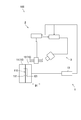
- FIG. 1 is a diagram showing a configuration of a mold system according to an embodiment of the present invention.
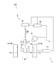
- FIG. 2 is a diagram showing a configuration of a mold system according to the embodiment of the present invention.
- FIG. 3 is a diagram showing a configuration of a mold system according to the embodiment of the present invention.
- FIG. 4 is a graph showing a temperature change of the mold according to the embodiment of the present invention.
- FIG. 5 is a flowchart showing nozzle abnormality detection processing according to the embodiment of the present invention.
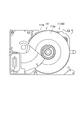
- FIG. 6 is a view showing an example of a mold according to the embodiment of the present invention.
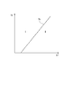
- FIG. 7 is a diagram illustrating an example of the relationship between the temperature before spraying and the temperature threshold according to the embodiment of the present invention.
- FIG. 8 is a diagram illustrating another example of the configuration of the nozzle abnormality detection device according to the embodiment of the present invention.
- FIG. 1 is a diagram illustrating a configuration of a mold system 100 according to the present embodiment. *
- the mold system 100 includes a mold apparatus 1, a spray apparatus 2, and a nozzle abnormality detection apparatus 3.
- the mold apparatus 1 has a mold 10. *
- the nozzle abnormality detection device 3 detects an abnormality of the spray device 2.
- the spraying apparatus 2 sprays a mold release agent on the mold 10 for producing a casting.
- spray process the process in which the spray device 2 sprays the release agent onto the mold 10 is referred to as “spray process”.
- the spraying process is performed for the purpose of suppressing seizure of the casting or reducing the mold release resistance of the casting.
- the spraying process is executed every time the casting is taken out from the mold 10 in the process of manufacturing the casting.
- the temperature of the mold 10 decreases due to the heat of vaporization of the mold release agent. *
- FIG. 2 is a diagram showing a configuration of the mold system 100 according to the present embodiment. Specifically, FIG. 2 shows a state where the mold 10 is closed. *
- the mold apparatus 1 includes a mold control apparatus 13 in addition to the mold 10.
- the mold 10 includes a fixed mold 11 and a movable mold 12. *
- the fixed mold 11 includes a first cavity surface 111, a gate, and a first cooling water channel. Cooling water for cooling the fixed mold 11 flows through the first cooling water channel.
- the movable mold 12 faces the fixed mold 11.
- the movable mold 12 has a second cavity surface 121 and a second cooling water channel.
- the first cavity surface 111 and the second cavity surface 121 face each other. Cooling water for cooling the movable mold 12 flows through the second cooling water channel.
- the movable mold 12 is movable along the mold movement direction D1. Specifically, when the mold 10 is closed, the movable mold 12 approaches the fixed mold 11 and contacts the fixed mold 11. The movable mold 12 is separated from the fixed mold 11 when the mold 10 is opened.
- mold closing the movement of the movable mold 12 close to the fixed mold 11 and the mold 10 closing
- the mold opening is described.
- a cavity 110 is formed inside the mold 10.
- the cavity 110 is constituted by a first cavity surface 111 and a second cavity surface 121.
- the molten metal passes through the gate and fills the cavity 110.
- the mold control device 13 has a processor such as a CPU (Central Processing Unit).
- the mold control apparatus 13 controls the operation of each part of the mold apparatus 1 by executing a mold control program. Specifically, the mold control device 13 controls the operation of the movable mold 12. Further, the mold control device 13 adjusts the flow rate of the cooling water flowing through the first cooling water channel of the fixed mold 11 and the flow rate of the cooling water flowing through the second cooling water channel of the movable mold 12.
- the mold control device 13 outputs a mold opening completion signal and a mold closing completion signal.
- the mold opening completion signal indicates that the mold 10 has been opened, that is, the mold opening has been completed.
- Completion of mold opening indicates, for example, that the movable mold 12 has moved to a position away from the fixed mold 11 by a predetermined distance and stopped.
- the mold closing completion signal indicates that the mold 10 is in a closed state, that is, the mold closing is completed.
- Completion of mold closing indicates, for example, that the movable mold 12 has moved to a position where it comes into contact with the fixed mold 11 and stopped. *
- FIG. 3 is a diagram showing a configuration of the mold system 100 according to the present embodiment.
- FIG. 3 shows a state where the mold 10 is opened. *
- the spray device 2 includes a plurality of nozzles 21, a nozzle elevating unit 22, and a spray control device 23. 1 to 3, four nozzles 21 are illustrated, but the number of nozzles 21 is not limited to four as long as it is plural. *
- the plurality of nozzles 21 spray the release agent on the mold 10 for a predetermined time.
- the predetermined time is set for each molded product.
- the predetermined time is preferably set to a time until the moisture of the sprayed release agent evaporates and the release agent after the moisture evaporates is fixed to the mold 10 and stabilized.
- the plurality of nozzles 21 spray the release agent on the first cavity surface 111 and the second cavity surface 121.
- a location where each nozzle 21 sprays the release agent may be referred to as a “nozzle-corresponding location”.
- Each nozzle-corresponding location is set in advance by adjusting the direction of each nozzle 21, for example.
- the orientation of each nozzle 21 is adjusted, for example, every time the molded product is changed. In other words, the orientation of each nozzle 21 is adjusted each time the mold 10 is changed.
- the nozzle raising / lowering part 22 has a drive mechanism.
- the drive mechanism includes a motor and a plurality of gears.
- the nozzle movement direction D2 is a direction that intersects the mold movement direction D1. That is, the plurality of nozzles 21 move along a direction that intersects the direction in which the movable mold 12 moves.
- the nozzle movement direction D2 is orthogonal to the mold movement direction D1.
- the plurality of nozzles 21 are movable between a first position P1 and a second position P2.
- the first position P ⁇ b> 1 indicates a position where the plurality of nozzles 21 perform the spray process on the mold 10.
- the second position P ⁇ b> 2 indicates a position where the plurality of nozzles 21 are farthest from the mold 10 in the range in which the plurality of nozzles 21 move.
- the spray control device 23 has a processor such as a CPU.
- the spray control device 23 controls the operation of each part of the spray device 2 by executing a spray control program.
- the spray control device 23 controls the operation of the nozzle elevating unit 22 to control the timing for starting the movement of the plurality of nozzles 21.
- the spray control device 23 receives the mold opening completion signal from the mold control device 13
- the spray control device 23 controls the operation of the nozzle elevating unit 22 to move the plurality of nozzles 21 from the second position P2 to the first position P1.
- the plurality of nozzles 21 move from the second position P2 toward the first position P1 when the movable mold 12 is separated from the fixed mold 11.
- the spray control apparatus 23 will control the operation
- the spray control apparatus 23 will control the operation
- finished will move the some nozzle 21 toward the 2nd position P2 from the 1st position P1.
- the spray control apparatus 23 will control the operation
- finished will move the some nozzle 21 toward the 2nd position P2 from the 1st position P1.
- the spray control apparatus 23 will control the operation
- finished will move the some nozzle 21 toward the 2nd position P2 from the 1st position P1.
- the spraying process ends the plurality of nozzles 21
- the spray control device 23 outputs a spray processing start signal, a spray processing completion signal, a movement start signal, and a movement completion signal.
- the spray processing start signal indicates that the spray processing by each nozzle 21 has started.
- the spray processing completion signal indicates that the spray processing by each nozzle 21 has been completed.
- the movement start signal indicates that the movement of the plurality of nozzles 21 has started.
- the movement start signal includes a first movement start signal and a second movement start signal.
- the first movement start signal indicates that the plurality of nozzles 21 have started moving from the second position P2 to the first position P1.
- the second movement start signal indicates that the plurality of nozzles 21 have started moving from the first position P1 to the second position P2.
- the movement completion signal indicates that the movement of the plurality of nozzles 21 has been completed.
- the movement completion signal includes a first movement completion signal and a second movement completion signal.
- the first movement completion signal indicates that the plurality of nozzles 21 have completed the movement from the second position P2 to the first position P1.
- the second movement completion signal indicates that the plurality of nozzles 21 have completed the movement from the first position P1 to the second position P2.
- the spray device 2 further includes a release agent supply unit.
- the release agent supply unit includes, for example, a tank, a booster, and an atomizer.
- the tank stores a release agent.
- the booster supplies the release agent stored in the tank to each of the plurality of nozzles 21.
- the atomizer sprays the release agent.
- the nozzle abnormality detection device 3 detects each abnormality of the plurality of nozzles 21.
- the nozzle abnormality detection device 3 includes an infrared camera 31 and a detection control device 32.
- the infrared camera 31 is an example of a temperature sensor.
- the detection control device 32 is an example of a control unit. *
- the infrared camera 31 measures the temperature of the mold 10. In the present embodiment, the infrared camera 31 measures the temperature of the first cavity surface 111. The infrared camera 31 outputs a signal indicating the temperature of the mold 10. In the present embodiment, the infrared camera 31 outputs a thermal image indicating the temperature distribution of the first cavity surface 111. *
- the infrared camera 31 has a lens and a light receiving element.
- the lens forms an infrared ray emitted from the mold 10 on the light receiving element.
- the light receiving element converts the received infrared light into an electrical signal and outputs it.
- the infrared camera 31 outputs data indicating a thermal image based on the electrical signal output from the light receiving element.
- the infrared camera 31 measures the temperature of the mold 10 in a non-contact manner. Thereby, the infrared camera 31 can measure the temperature of the location which cannot be measured by the contact method.
- the detection control device 32 has a processor such as a CPU.
- the detection control device 32 controls the operation of each part of the nozzle abnormality detection device 3 by executing a detection control program. *
- the detection control device 32 has a storage area.
- the storage area stores various data such as a control program.
- the storage area is configured by a storage device and a semiconductor memory.
- the storage device is configured by, for example, an HDD (Hard Disk Drive) and / or an SSD (Solid State Drive).
- the semiconductor memory includes, for example, a RAM (Random Access Memory) and a ROM (Read Only Memory).
- the detection control device 32 associates each of the plurality of nozzles 21 with a location (nozzle-corresponding location) where each nozzle 21 sprays the release agent, and stores them in the storage area. *
- the detection control device 32 receives a mold opening completion signal and a mold closing completion signal from the mold control device 13. Further, the detection control device 32 receives a spray processing start signal, a spray processing completion signal, a movement start signal, and a movement completion signal from the spray control device 23. *
- the detection control device 32 executes a nozzle abnormality detection process.
- the detection control device 32 acquires a difference temperature between the temperature before the spray process and the temperature after the spray process, and determines whether or not the difference temperature is equal to or lower than the temperature threshold value. If the detection control device 32 determines that the differential temperature is equal to or lower than the temperature threshold value, it detects a nozzle abnormality.
- the temperature before the spraying process indicates the temperature of the mold 10 before the spraying process is started. Specifically, the temperature before the spraying process indicates the temperature of the mold 10 from the mold opening completion state to before the spraying process is started.
- the temperature after the spraying process indicates the temperature of the mold 10 after the spraying process is finished.
- the temperature after the spraying process indicates the temperature of the mold 10 after the spraying process is completed and before the mold closing is completed in order to mold the next molded product.
- the detection control device 32 acquires the temperature before spraying and the temperature after spraying for each divided region.
- the divided area indicates an area obtained by dividing the thermal image (temperature distribution of the mold 10) output from the infrared camera 31 into a predetermined number. The divided area is determined according to the resolution of the infrared camera 31, for example. *
- FIG. 4 is a graph showing a temperature change of the mold 10 according to the present embodiment.
- FIG. 4 shows the temperature change of the metal mold
- the target location corresponds to one of a plurality of divided regions.
- the horizontal axis shown in FIG. 4 indicates time Tm, and the vertical axis indicates the temperature T of the target location. *
- the temperatures of the target locations in three cycles are plotted.
- One cycle indicates a period from when the mold is closed to mold one molded product to when the mold is closed to mold the next molded product.
- the temperature of the target portion repeatedly rises and falls every cycle.
- the temperature change of the target portion will be described by taking the first cycle C1 as an example.
- the time Tm1 shown in FIG. 4 indicates the time when the mold closing is completed
- the time Tm2 indicates the time when the molten metal is injected
- the time Tm3 indicates the time when the mold opening is completed.
- the time Tm4 indicates the time when the movement of the plurality of nozzles 21 to the first position P1 starts
- the time Tm5 indicates the time when the spraying process starts
- the time Tm6 indicates the time when the spraying process ends.
- the time Tm7 indicates the time when the movement of the plurality of nozzles 21 to the second position P2 is completed
- the time Tm8 indicates the time when the mold closing is completed in the next cycle (second cycle C2). Note that cooling water always flows through the first cooling water channel and the second cooling water channel. *
- the pre-spraying temperature T ⁇ b> 1 indicates the temperature at the target location when the plurality of nozzles 21 start moving toward the first position P ⁇ b> 1 (time Tm ⁇ b> 4).
- the post-spraying temperature T2 indicates the temperature of the target portion at the time (time Tm7) when the movement of the plurality of nozzles 21 to the second position P2 is completed.
- FIG. 5 is a flowchart showing nozzle abnormality detection processing according to the present embodiment.
- the nozzle abnormality detection process is started when the detection control device 32 receives a mold opening completion signal from the mold control device 13. *
- the detection control device 32 acquires the pre-spraying temperature T1 of the mold 10 (step S1). Specifically, the detection control device 32 acquires the pre-spraying temperature T1 of each part of the mold 10 corresponding to each divided region. In the present embodiment, the detection control device 32 acquires the temperature of the mold 10 when receiving the first movement start signal from the spray control device 23. In other words, the detection control device 32 acquires the temperature of the mold 10 when the plurality of nozzles 21 start moving toward the first position P1 (Tm4 shown in FIG. 4). *
- the detection control device 32 stands by until the spraying process ends (step S2: No). Specifically, the detection control device 32 determines whether or not the spray processing has been completed depending on whether or not a spray processing completion signal has been received from the spray control device 23. Specifically, when a spray processing completion signal is received from the spray control device 23, it is determined that the spray processing has ended.
- the detection control device 32 acquires the post-spraying temperature T2 of the mold 10 (step S3). Specifically, the detection control device 32 acquires the post-spray processing temperature T2 of each part of the mold 10 corresponding to each divided region.
- the detection control device 32 acquires the temperature of the mold 10 when receiving the second movement completion signal from the spray control device 23. In other words, the detection control device 32 acquires the temperature of the mold 10 when the movement of the plurality of nozzles 21 to the second position P2 is completed (time Tm7 shown in FIG. 4). *
- the detection control device 32 acquires the difference temperature ⁇ T (step S4). Specifically, the detection control device 32 acquires the differential temperature ⁇ T of the mold 10 by subtracting the post-spray processing temperature T2 from the pre-spray processing temperature T1. Specifically, the detection control device 32 acquires a difference temperature ⁇ T at each location of the mold 10 corresponding to each divided region.
- the detection control device 32 determines whether or not the differential temperature ⁇ T of the mold 10 is equal to or lower than the temperature threshold (step S5).
- the temperature threshold is a threshold set in advance for the differential temperature ⁇ T. In the present embodiment, the temperature threshold is a constant value, for example, 50 ° C. If the detection control device 32 determines that the differential temperature ⁇ T of the mold 10 is not equal to or lower than the temperature threshold (step S5: No), the nozzle abnormality detection process ends. On the other hand, if the detection control device 32 determines that the differential temperature ⁇ T of the mold 10 is equal to or lower than the temperature threshold (step S5: Yes), it determines that an abnormality has occurred in the nozzle 21.
- the detection control device 32 detects a nozzle abnormality and ends the nozzle abnormality detection process. Specifically, the detection control device 32 determines whether or not the difference temperature ⁇ T is equal to or lower than the temperature threshold value for each divided region. The detection control device 32 determines that an abnormality has occurred in the nozzle 21 when the difference temperature ⁇ T in at least one of the divided regions is equal to or lower than the temperature threshold value. Further, the detection control device 32 associates each of the plurality of nozzles 21 stored in the storage area described with reference to FIG. 3 with a location (nozzle-corresponding location) where each nozzle 21 sprays the release agent. Based on this, the nozzle 21 in which an abnormality has occurred is identified. *
- the present embodiment has been described above.
- the temperature of the nozzle corresponding part corresponding to the nozzle 21 having the wrong spraying direction does not decrease. That is, the temperature of the mold 10 does not decrease.
- the temperature of the nozzle corresponding part corresponding to the clogged nozzle 21 does not decrease. That is, the temperature of the mold 10 does not decrease.
- the infrared camera 31 measures the temperature of the mold 10
- the detection control device 32 acquires the differential temperature ⁇ T of the mold 10 based on the signal output from the infrared camera 31.
- the detection control device 32 detects a nozzle abnormality depending on whether or not the difference temperature ⁇ T is equal to or lower than the temperature threshold. Therefore, according to the present embodiment, it is possible to detect an error in the spraying direction of each nozzle 21 and clogging of each nozzle 21 by measuring the temperature of the mold 10. Therefore, the detection accuracy of the nozzle abnormality is improved. As a result, it is possible to suppress deterioration of the quality of the molded product. *
- the detection control device 32 detects the nozzle abnormality based on the difference temperature ⁇ T between the temperature T1 before the spraying process and the temperature T2 after the spraying process. Therefore, it is possible to suppress erroneous detection of nozzle abnormality due to variations in the pre-spraying temperature T1. As a result, the detection accuracy of the nozzle abnormality is improved.
- the detection control device 32 sprays the temperature of the mold 10 at the time (time Tm7 shown in FIG. 4) when the movement of the plurality of nozzles 21 from the first position P1 to the second position P2 is completed. Acquired as the post-temperature T2.
- the second position P ⁇ b> 2 is a position where the plurality of nozzles 21 are farthest from the mold 10 in the range in which the plurality of nozzles 21 move. Therefore, the detection control device 32 can acquire the post-spraying temperature T2 without being obstructed by the plurality of nozzles 21.
- the detection control device 32 determines the temperature of the mold 10 at the time when the plurality of nozzles 21 start moving toward the first position P1 (time Tm4 shown in FIG. 4). Obtained as T1. That is, the pre-spraying temperature T1 is a temperature at the time when the plurality of nozzles 21 are located at the second position P2. Therefore, the detection control device 32 can acquire the pre-spray processing temperature T ⁇ b> 1 without being hindered by the plurality of nozzles 21. *
- the detection control device 32 sets the temperature at the time when the plurality of nozzles 21 start moving toward the first position P1 (time Tm4 shown in FIG. 4) as the pre-spray processing temperature T1. get.
- the detection control device 32 acquires the temperature at a time point closer to the time point when the spraying process is started in a period in which the temperature measurement is not hindered by the plurality of nozzles 21. Therefore, the detection control device 32 is used for the mold 10 by spraying.
- the temperature change can be obtained more accurately. As a result, the detection accuracy of the nozzle abnormality is improved.
- the detection control device 32 acquires the temperature at the time (time Tm7 shown in FIG. 4) when the movement of the plurality of nozzles 21 to the second position P2 is completed as the post-spray processing temperature T2. To do. In other words, the detection control device 32 measures the temperature at a time point closer to the time point when the spraying process is completed in a period in which the temperature measurement is not hindered by the plurality of nozzles 21. Therefore, the detection control device 32 can more accurately acquire the temperature change of the mold 10 due to the spraying process. As a result, the detection accuracy of the nozzle abnormality is improved. *
- the infrared camera 31 measures the temperature of the entire surface of the first cavity surface 111 of the mold 10, but the infrared camera 31 measures the temperature of a part (predetermined location) of the first cavity surface 111. You may measure.
- the differential temperature ⁇ T acquired by the detection control device 32 may indicate the differential temperature ⁇ T at a predetermined location of the mold apparatus 1.
- the detection control device 32 can acquire a more detailed (high resolution) temperature distribution by narrowing down the part measured by the infrared camera 31 to a part of the first cavity surface 111. Thereby, the detection precision of the nozzle abnormality corresponding to a predetermined location can be improved.
- a predetermined location may be changed according to the molded product which the metal mold apparatus 1 shape
- FIG. 6 is a diagram illustrating an example of the mold 10 according to the present embodiment. Specifically, FIG. 6 shows the first cavity surface 111 of the fixed mold 11. A mold 10 shown in FIG. 6 is a mold for molding a base plate constituting the HDD. *
- the infrared camera 31 may measure the important part 111a and the thick part 111b.
- the infrared camera 31 may measure only the important part 111a.
- the important part 111 a is a part where a part of the mold 10 having a high degree of dimensional importance is formed.
- the important location 111a is a location where it is necessary to ensure the dimensional accuracy of the molded product.
- the important part 111a is a part for molding a part where the platter is arranged in the base plate. In the example shown in FIG.
- the thick portion 111 b is a portion where the frame of the base plate is formed.
- the infrared camera 31 measures only the important portion 111a, it is possible to detect a nozzle abnormality corresponding to a portion having a high dimensional importance. As a result, the quality of the molded product can be improved.
- the temperature threshold value is a constant value, but the temperature threshold value may change according to the pre-spraying temperature T1 as shown in FIG. *
- FIG. 7 is a diagram illustrating an example of the relationship between the pre-spraying temperature T1 and the temperature threshold Th according to the present embodiment.
- a first region I shown in FIG. 7 indicates a region where the difference temperature ⁇ T is equal to or lower than the temperature threshold Th, and a second region II indicates a region where the difference temperature ⁇ T is greater than the temperature threshold.
- the temperature threshold Th is preferably increased as the pre-spray processing temperature T1 is increased, and is preferably decreased as the pre-spray processing temperature T1 is decreased.
- the pre-spraying temperature T1 is low, the differential temperature ⁇ T is small, and when the pre-spraying temperature T1 is high, the differential temperature ⁇ T is large. Therefore, for example, the detection control device 32 can suppress erroneous detection due to the difference temperature ⁇ T being equal to or lower than the temperature threshold due to the low pre-spraying temperature T1.
- the pre-spraying temperature T1 is a temperature at the time when the plurality of nozzles 21 starts moving toward the first position P1, but the pre-spraying temperature T1 is not limited to this. .
- the detection control device 32 when the temperature measurement by the infrared camera 31 is not hindered by the plurality of nozzles 21 located at the first position P1, the detection control device 32 is when the plurality of nozzles 21 have finished moving toward the first position P1.
- the temperature of the mold 10 may be acquired as the pre-spraying temperature T1.
- the detection control apparatus 32 can acquire the temperature of the metal mold
- the temperature T2 after the spraying process is a temperature at the time when the movement of the plurality of nozzles 21 to the second position P2 is completed, but the temperature T2 after the spraying process is It is not limited.
- the detection control device 32 determines the temperature of the mold 10 immediately after the spraying process by the plurality of nozzles 21 is finished. May be acquired as the post-spray processing temperature T2. Thereby, the detection control apparatus 32 can acquire the temperature of the metal mold
- the infrared camera 31 demonstrated the structure which measures the temperature of the fixed metal mold
- the mold system 100 includes the mold control device 13, the spray control device 23, and the detection control device 32, but the mold device 1, the spray device 2, and the nozzle abnormality detection device 3 are the same. It may be controlled by one control device.
- the control device is, for example, a personal computer. *
- FIG. 8 is a diagram illustrating another example of the nozzle abnormality detection device 3 according to the present embodiment. *
- the nozzle abnormality detection device 3 illustrated in FIG. 8 includes a first infrared camera 311 and a second infrared camera 312.
- the first infrared camera 311 measures the temperature of the fixed mold 11 (first cavity surface 111).
- the second infrared camera 312 measures the temperature of the movable mold 12 (second cavity surface 121).
- the detection control device 32 can acquire the temperature distribution of the movable mold 12 in addition to the temperature distribution of the fixed mold 11. Therefore, it is possible to detect an abnormality of the nozzle 21 that sprays the mold release agent on the fixed mold 11 and an abnormality of the nozzle 21 that sprays the mold release agent on the movable mold 12.
- the present invention can be suitably used in the field of molds.
- Mold device 2 Mold device 2, Spraying device 3, Nozzle abnormality detection device 10, Mold 11, Fixed mold 12, Movable mold 31, Infrared camera (temperature sensor) 32, Thickness control part 111 Pre-spraying temperature T2 Post-spraying temperature Th Th Threshold
Landscapes
- Engineering & Computer Science (AREA)
- Mechanical Engineering (AREA)
- Injection Moulding Of Plastics Or The Like (AREA)
Abstract
L'invention concerne un instrument de détection d'une anomalie d'une buse, ledit instrument améliorant la précision de détection d'anomalie de buse et supprimant toute réduction de la qualité d'articles moulés. Cet instrument (3) pour détecter une anomalie d'une buse détecte une anomalie d'une buse (21) pour pulvériser un agent de démoulage sur un moule (10). L'instrument (3) pour détecter une anomalie d'une buse comporte un capteur de température (31) et une unité de commande (32). Le capteur de température (31) mesure la température du moule (10) et délivre un signal indiquant la température du moule (10). L'unité de commande (32) acquiert la température du moule (10) sur la base du signal émis par le capteur de température (31). L'unité de commande (32) acquiert une température de différence qui indique la différence entre la température de pré-pulvérisation et la température de post-pulvérisation. La température de pré-pulvérisation indique la température du moule (10) avant le début d'un traitement de pulvérisation dans lequel la buse (21) pulvérise un agent de démoulage sur le moule (10). La température de post-pulvérisation indique la température du moule (10) après achèvement du traitement de pulvérisation. L'unité de commande (32) détermine si la température de différence est égale ou inférieure à une valeur de seuil de température, et une anomalie de la buse (21) est détectée si la température de différence est jugée égale ou inférieure à la valeur de seuil de température.
Applications Claiming Priority (2)
| Application Number | Priority Date | Filing Date | Title |
|---|---|---|---|
| JP2018070824 | 2018-04-02 | ||
| JP2018-070824 | 2018-04-02 |
Publications (1)
| Publication Number | Publication Date |
|---|---|
| WO2019194183A1 true WO2019194183A1 (fr) | 2019-10-10 |
Family
ID=68100277
Family Applications (1)
| Application Number | Title | Priority Date | Filing Date |
|---|---|---|---|
| PCT/JP2019/014648 Ceased WO2019194183A1 (fr) | 2018-04-02 | 2019-04-02 | Instrument de détection d'anomalie de buse |
Country Status (1)
| Country | Link |
|---|---|
| WO (1) | WO2019194183A1 (fr) |
Cited By (1)
| Publication number | Priority date | Publication date | Assignee | Title |
|---|---|---|---|---|
| CN114593499A (zh) * | 2022-03-11 | 2022-06-07 | 广东美的暖通设备有限公司 | 一种喷嘴脏堵识别方法及装置 |
Citations (6)
| Publication number | Priority date | Publication date | Assignee | Title |
|---|---|---|---|---|
| JPS6092047A (ja) * | 1983-10-26 | 1985-05-23 | Toshiba Mach Co Ltd | ダイカスト機のスプレイ装置 |
| JPH08174174A (ja) * | 1994-12-28 | 1996-07-09 | Honda Motor Co Ltd | 鋳造金型の離型剤の塗布方法 |
| JPH09122870A (ja) * | 1995-11-02 | 1997-05-13 | Tokai Rika Co Ltd | 金型の温度制御方法及び金型の温度制御装置 |
| JP2005028335A (ja) * | 2003-07-10 | 2005-02-03 | Tc:Kk | 噴霧装置の分配器 |
| JP2006341284A (ja) * | 2005-06-09 | 2006-12-21 | Toyota Motor Corp | スプレー剤塗布方法及びスプレー剤塗布装置 |
| JP2015150617A (ja) * | 2014-02-19 | 2015-08-24 | リョーエイ株式会社 | 金型スプレー方法及び金型スプレーシステム |
-
2019
- 2019-04-02 WO PCT/JP2019/014648 patent/WO2019194183A1/fr not_active Ceased
Patent Citations (6)
| Publication number | Priority date | Publication date | Assignee | Title |
|---|---|---|---|---|
| JPS6092047A (ja) * | 1983-10-26 | 1985-05-23 | Toshiba Mach Co Ltd | ダイカスト機のスプレイ装置 |
| JPH08174174A (ja) * | 1994-12-28 | 1996-07-09 | Honda Motor Co Ltd | 鋳造金型の離型剤の塗布方法 |
| JPH09122870A (ja) * | 1995-11-02 | 1997-05-13 | Tokai Rika Co Ltd | 金型の温度制御方法及び金型の温度制御装置 |
| JP2005028335A (ja) * | 2003-07-10 | 2005-02-03 | Tc:Kk | 噴霧装置の分配器 |
| JP2006341284A (ja) * | 2005-06-09 | 2006-12-21 | Toyota Motor Corp | スプレー剤塗布方法及びスプレー剤塗布装置 |
| JP2015150617A (ja) * | 2014-02-19 | 2015-08-24 | リョーエイ株式会社 | 金型スプレー方法及び金型スプレーシステム |
Cited By (2)
| Publication number | Priority date | Publication date | Assignee | Title |
|---|---|---|---|---|
| CN114593499A (zh) * | 2022-03-11 | 2022-06-07 | 广东美的暖通设备有限公司 | 一种喷嘴脏堵识别方法及装置 |
| CN114593499B (zh) * | 2022-03-11 | 2023-09-19 | 广东美的暖通设备有限公司 | 一种喷嘴脏堵识别方法及装置 |
Similar Documents
| Publication | Publication Date | Title |
|---|---|---|
| JP2559651B2 (ja) | 射出成形の制御方法および装置 | |
| CN104416875B (zh) | 具备模盘中心位置调整功能的注塑成型机的合模装置 | |
| WO2019194183A1 (fr) | Instrument de détection d'anomalie de buse | |
| CN120287526A (zh) | 基于机器视觉的模具加工注塑方法、装置、设备及介质 | |
| JP7260417B2 (ja) | 射出成形機の異常検出装置 | |
| JP3842868B2 (ja) | 射出成形方法およびその装置 | |
| JP2007222890A (ja) | 金型の温度制御方法及び金型の温度制御装置 | |
| JP2018140612A (ja) | 射出成形機および射出成形方法 | |
| US20200206998A1 (en) | Quality prediction system and molding machine | |
| US7454307B2 (en) | Method and system for detecting tilt or shift of wafer transferred onto hot plate in real time, and method system for monitoring baking process of wafers in real time | |
| JP3475725B2 (ja) | 射出成形方法およびその装置 | |
| CN101636254A (zh) | 基于插塞吹落的确定而识别模制物件的质量 | |
| JP4767192B2 (ja) | 射出成形装置、射出成形方法 | |
| JP2015150617A (ja) | 金型スプレー方法及び金型スプレーシステム | |
| JP2021041435A (ja) | 鋳造金型用の温度測定装置 | |
| CN117983781A (zh) | 压铸铸造方法及压铸铸造系统 | |
| JP7483436B2 (ja) | 射出成形機及びステータス決定装置 | |
| JP2006289773A (ja) | 成形機監視装置、方法及びプログラム | |
| TWI588006B (zh) | 射出成型機鎖模力設定方法及其系統 | |
| JP2001198964A (ja) | 射出成形用金型の温度制御装置と射出成形用金型の温度制御方法 | |
| CN121571615B (zh) | 一种连铸铸坯移动追踪的方法 | |
| JPH0322286B2 (fr) | ||
| KR101119949B1 (ko) | 금형 내부의 수지도달시점 결정 방법 | |
| JPH0414423A (ja) | 樹脂成形品の反り量制御方法 | |
| JP2024175633A (ja) | 方法、情報処理システム及びプログラム |
Legal Events
| Date | Code | Title | Description |
|---|---|---|---|
| 121 | Ep: the epo has been informed by wipo that ep was designated in this application |
Ref document number: 19781745 Country of ref document: EP Kind code of ref document: A1 |
|
| NENP | Non-entry into the national phase |
Ref country code: DE |
|
| 122 | Ep: pct application non-entry in european phase |
Ref document number: 19781745 Country of ref document: EP Kind code of ref document: A1 |
|
| NENP | Non-entry into the national phase |
Ref country code: JP |