WO2019194237A1 - Couvercle de canette - Google Patents
Couvercle de canette Download PDFInfo
- Publication number
- WO2019194237A1 WO2019194237A1 PCT/JP2019/014849 JP2019014849W WO2019194237A1 WO 2019194237 A1 WO2019194237 A1 WO 2019194237A1 JP 2019014849 W JP2019014849 W JP 2019014849W WO 2019194237 A1 WO2019194237 A1 WO 2019194237A1
- Authority
- WO
- WIPO (PCT)
- Prior art keywords
- lid
- center
- panel
- tab
- slope
- Prior art date
- Legal status (The legal status is an assumption and is not a legal conclusion. Google has not performed a legal analysis and makes no representation as to the accuracy of the status listed.)
- Ceased
Links
Images

Classifications
-
- B—PERFORMING OPERATIONS; TRANSPORTING
- B65—CONVEYING; PACKING; STORING; HANDLING THIN OR FILAMENTARY MATERIAL
- B65D—CONTAINERS FOR STORAGE OR TRANSPORT OF ARTICLES OR MATERIALS, e.g. BAGS, BARRELS, BOTTLES, BOXES, CANS, CARTONS, CRATES, DRUMS, JARS, TANKS, HOPPERS, FORWARDING CONTAINERS; ACCESSORIES, CLOSURES, OR FITTINGS THEREFOR; PACKAGING ELEMENTS; PACKAGES
- B65D17/00—Rigid or semi-rigid containers specially constructed to be opened by cutting or piercing, or by tearing of frangible members or portions
- B65D17/28—Rigid or semi-rigid containers specially constructed to be opened by cutting or piercing, or by tearing of frangible members or portions at lines or points of weakness
- B65D17/34—Arrangement or construction of pull or lift tabs
-
- B—PERFORMING OPERATIONS; TRANSPORTING
- B65—CONVEYING; PACKING; STORING; HANDLING THIN OR FILAMENTARY MATERIAL
- B65D—CONTAINERS FOR STORAGE OR TRANSPORT OF ARTICLES OR MATERIALS, e.g. BAGS, BARRELS, BOTTLES, BOXES, CANS, CARTONS, CRATES, DRUMS, JARS, TANKS, HOPPERS, FORWARDING CONTAINERS; ACCESSORIES, CLOSURES, OR FITTINGS THEREFOR; PACKAGING ELEMENTS; PACKAGES
- B65D17/00—Rigid or semi-rigid containers specially constructed to be opened by cutting or piercing, or by tearing of frangible members or portions
- B65D17/28—Rigid or semi-rigid containers specially constructed to be opened by cutting or piercing, or by tearing of frangible members or portions at lines or points of weakness
- B65D17/401—Rigid or semi-rigid containers specially constructed to be opened by cutting or piercing, or by tearing of frangible members or portions at lines or points of weakness characterised by having the line of weakness provided in an end wall
- B65D17/4012—Rigid or semi-rigid containers specially constructed to be opened by cutting or piercing, or by tearing of frangible members or portions at lines or points of weakness characterised by having the line of weakness provided in an end wall for opening partially by means of a tearing tab
-
- B—PERFORMING OPERATIONS; TRANSPORTING
- B65—CONVEYING; PACKING; STORING; HANDLING THIN OR FILAMENTARY MATERIAL
- B65D—CONTAINERS FOR STORAGE OR TRANSPORT OF ARTICLES OR MATERIALS, e.g. BAGS, BARRELS, BOTTLES, BOXES, CANS, CARTONS, CRATES, DRUMS, JARS, TANKS, HOPPERS, FORWARDING CONTAINERS; ACCESSORIES, CLOSURES, OR FITTINGS THEREFOR; PACKAGING ELEMENTS; PACKAGES
- B65D2517/00—Containers specially constructed to be opened by cutting, piercing or tearing of wall portions, e.g. preserving cans or tins
- B65D2517/0001—Details
- B65D2517/001—Action for opening container
- B65D2517/0013—Action for opening container pull-out tear panel, e.g. by means of a tear-tab
-
- B—PERFORMING OPERATIONS; TRANSPORTING
- B65—CONVEYING; PACKING; STORING; HANDLING THIN OR FILAMENTARY MATERIAL
- B65D—CONTAINERS FOR STORAGE OR TRANSPORT OF ARTICLES OR MATERIALS, e.g. BAGS, BARRELS, BOTTLES, BOXES, CANS, CARTONS, CRATES, DRUMS, JARS, TANKS, HOPPERS, FORWARDING CONTAINERS; ACCESSORIES, CLOSURES, OR FITTINGS THEREFOR; PACKAGING ELEMENTS; PACKAGES
- B65D2517/00—Containers specially constructed to be opened by cutting, piercing or tearing of wall portions, e.g. preserving cans or tins
- B65D2517/0001—Details
- B65D2517/001—Action for opening container
- B65D2517/0014—Action for opening container pivot tab and push-down tear panel
-
- B—PERFORMING OPERATIONS; TRANSPORTING
- B65—CONVEYING; PACKING; STORING; HANDLING THIN OR FILAMENTARY MATERIAL
- B65D—CONTAINERS FOR STORAGE OR TRANSPORT OF ARTICLES OR MATERIALS, e.g. BAGS, BARRELS, BOTTLES, BOXES, CANS, CARTONS, CRATES, DRUMS, JARS, TANKS, HOPPERS, FORWARDING CONTAINERS; ACCESSORIES, CLOSURES, OR FITTINGS THEREFOR; PACKAGING ELEMENTS; PACKAGES
- B65D2517/00—Containers specially constructed to be opened by cutting, piercing or tearing of wall portions, e.g. preserving cans or tins
- B65D2517/0001—Details
- B65D2517/0058—Other details of container end panel
- B65D2517/0074—Local recess in container end panel
- B65D2517/0079—Local recess in container end panel located beneath tab hand grip to facilitate initial lifting
Definitions
- the present invention relates to an easily openable can lid that improves the opening of a tab.
- the score breaking tab is fixed to the can lid body.
- the tab is fixed by a rivet portion provided at the center of the can lid, one end is overlaid on the planned opening portion, and the other end extends to the vicinity of the periphery of the can lid.
- the can lid body is provided with an embossed portion in the vicinity of the rear end of the tab hooking portion of the tab.
- the finger is tabbed. This makes it easier to hang on the rear edge of the finger-holding part, and the opening operability is improved.
- a tip-up portion is provided in the finger hook portion, and the distance between the bottom surface of the embossed portion and the finger hook portion is increased.
- the can lid of Patent Document 1 has improved finger gripping performance due to the embossed portion and the tip-up portion, the movable range in the tab short side direction of the finger hung on the rear end of the finger hooked portion is large.
- the finger when the tab is raised, the finger may be displaced from the center of the finger catching portion, and the direction of the force acting on the tab may be applied obliquely with respect to the lid center direction. There is a risk of opening failure.
- the embossed part and the tip-up part are provided, the finger grip is improved, but the gap with the panel surface of the can lid becomes large. There is an increased risk that the can body tilts and the can bottom is caught by the finger hook portion of the tab, and an unexpected opening is generated.
- the object of the present invention is to provide an easily openable can lid that can act as much as possible in the direction of the center of the lid while ensuring the finger-holding property to the tab by devising the shape of the embossed portion. There is. It is another object of the present invention to provide an easily openable can lid that can cause the direction of the trigger to be as close as possible to the center of the lid and can prevent the occurrence of an unexpected opening.
- the present invention has a can lid body with a score breaking tab fixed thereto,
- the can lid provided with an embossed portion into which the fingertip enters near the rear end of the finger hook portion of the tab
- the slope on the rear end side of the finger hook portion of the embossed portion includes a guide recess for guiding the fingertip that extends toward the center of the can lid and at least a position facing the widthwise central portion of the back surface of the finger hook portion. It is characterized by being.
- the raising direction is centered on the lid body. Can be caused accurately.
- the present invention can be configured as follows. 1.
- the width of the guide recess is gradually narrowed toward the center of the can lid. In this way, the fingertip is naturally guided to the center in the width direction on the back surface of the finger hook portion.
- the bottom of the guide recess is an inclined surface that gradually becomes shallower from the bottom surface of the embossed portion toward the center of the can lid, and has a smaller inclination angle than the inclined surface of the embossed portion opposite to the center of the can lid. In this way, the tab is caused as the fingertip is gradually lifted. 3.
- the embossed portion has a bottom surface and an inner peripheral wall that surrounds the bottom surface, and the inner peripheral wall has a first inclined surface opposite to the can lid center, a second inclined surface on the can lid center side, and both ends of the first inclined surface.
- the pair of side slopes are inclined in a direction gradually approaching each other toward the center of the can lid, and constitute a part of the guide recess. If it does in this way, a side part slope will function as a part of guidance crevice, and it will become easy to guide a fingertip to the width direction central part of a finger hook part back. 4).
- the can lid main body is provided with convex portions on both sides of the embossed portion in the vicinity of the rear end of the tab.
- the slope on the embossed portion side of the convex portion is an inclined surface continuous with the side slope of the embossed portion. In this way, when the fingertip is displaced from the center of the can lid, the finger hits the slope of the convex portion having a height, and is more easily guided to the guiding concave portion. 6).
- the height of the convex portion is in the range of 0.5 mm to 1.2 mm.
- the convex portion is set to a height of about 0.5 mm or more, even when used in a positive pressure can in which the tab is lifted up, the unexpected opening is unlikely to occur.
- a more preferable range is 0.7 mm or more.
- the higher the height of the convex portion the higher the effect of suppressing the unexpected opening, but the amount of decrease in the thickness of the convex portion increases, which causes problems in formability such as insufficient strength and cut off of the coating film. If it is 1.2 mm or less, it will be within a level where there is no practical problem. 7).
- the distance between the vertices of the convex portions is in the range of 13 mm ⁇ 2 mm.
- the can lid body has a circular center panel, and the center panel is located on the outer peripheral edge side of the first panel surface and on the inner side of the first panel surface, and is one step lower from the inner peripheral edge of the first panel surface through a step portion.
- the convex portion is provided on the first panel surface. If it is provided on the first panel surface, it is possible to suppress a reduction in the plate thickness of the convex portion, which is more advantageous in terms of formability than the second panel surface. 9.
- the embossed portion is a region of the second panel surface and is provided close to the stepped portion with the first panel surface,
- the embossed portion has a bottom surface and an inner peripheral wall surrounding the bottom surface.
- the inner peripheral wall includes a first inclined surface on the side opposite to the can lid center, a second inclined surface on the can lid center side, and a first inclined surface.
- the fingertip put in the embossed part will be surrounded by the 1st slope and side slope which are higher than the 2nd slope side, and will be easy to be guided to the guidance crevice of the 2nd slope with low height.
- a tab for score breaking is fixed, and the can lid having an embossed portion where the fingertip enters near the rear end of the tab hook portion,
- the can lid body is provided with convex portions on both sides of the embossed portion in the vicinity of the rear end of the tab hooking portion,
- the height of the convex portion is set in a range of 0.5 mm to 1.2 mm.
- the height of the convex portion is set to about 0.5 mm or more, as in the case of a positive pressure can, even when the internal pressure acts and the can lid swells and the tab is lifted up, the unexpected opening is unlikely to occur. More preferably, it is 0.7 mm or more.
- the higher the height of the convex portion the higher the effect of suppressing the unexpected opening, but the amount of decrease in the thickness of the convex portion increases, which causes problems in formability such as insufficient strength and cut off of the coating film. If it is 1.2 mm or less, it will be within a level where there is no practical problem.
- this invention can be comprised as follows. 1. The distance between the vertices of the convex portions is in the range of 13 mm ⁇ 2 mm. If it does in this way, it will become easy to guide a fingertip to the width direction center part of a finger hook part. 2.
- the can lid body has a circular center panel, and the center panel is located on the outer peripheral edge side of the first panel surface and on the inner side of the first panel surface, and is one step lower from the inner peripheral edge of the first panel surface through a step portion.
- a second panel surface, The convex portion is provided on the first panel surface. If it is provided on the first panel surface, it is possible to suppress a reduction in the plate thickness of the convex portion, which is more advantageous in terms of formability than the second panel surface.
- the raising direction is centered on the lid body. Can be caused accurately.
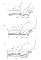
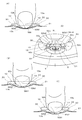
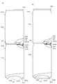
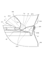
- FIGS. 3A to 3C are explanatory diagrams of the tab raising operation. 4 (A) to 4 (C) are explanatory views of the causing operation when FIG.
- FIG. 5 shows a can body for an evaluation test.
- FIG. 5A is a view showing a state in which the first type can body and FIG. .
- FIG. 6 is an enlarged cross-sectional view of a main part of the loading portion of the first can body in FIG.
- FIG. 7 is an enlarged cross-sectional view of the main part of the loading portion of the second can body in FIG.
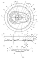
- FIG. 1 shows an easily openable can lid according to an embodiment of the present invention.
- the easily openable can lid includes a can lid main body 1 in which a score 6 surrounding the planned opening 8 serving as a drinking mouth is formed, and a score breaking tab 10 fixed to the can lid main body 1.
- the can lid body 1 is formed continuously with a circular center panel 2, a chuck wall radius 3 projecting downward from the periphery of the center panel 2, a chuck wall 4 rising from the outer wall of the chuck wall radius 3, and the chuck wall 4.
- a seaming panel 5 is provided.
- the center panel 2 has a first panel surface 21 on the peripheral side of the panel, and a second panel surface 22 that forms a recessed portion that is one step lower than the first panel surface 21 inside the first panel surface 21.
- the second panel surface 22 is partitioned from the first panel surface 21 by a step portion 22 b, and the planned opening portion 8 and the tab 10 are disposed on the second panel surface 22.
- the tab 10 is of a steion type and is fixed to a rivet portion 7 protruding from the center O (can lid center) of the circular center panel 2.
- the planned opening portion 8 is formed in one semicircular region when it is divided in half by the first center line M passing through the panel center O of the center panel 2, and the score 6 is in the vicinity of the rivet portion 7.
- the opening by the tab 10 is opened toward the end portion 6b with the initial end portion 6a being initially broken.
- the tab 10 is a plate-like member formed in a substantially track shape.
- the tab 10 is disposed along a second center line N that passes through the panel center O and is orthogonal to the first center line M, the tab tip 11 exceeds the panel center O, and further exceeds the start end 6 a of the score 6.
- the finger hooking portion 13 of the tab 10 is disposed near the periphery of the center panel 2 on the side opposite to the scheduled opening portion 8 with respect to the panel center O.
- the finger hook portion 13 of the tab 10 extends linearly in a direction orthogonal to the second center line N, and both end portions reach the side portions 16 and 16 of the tab 10 via the corner portions 13c and 13c. It has become.
- the tab 10 is formed with an elliptical hole 14 adjacent to the finger hook portion 13, and in this example, the finger hook portion 13 is a narrow plate-like shape between the rear end 13 a and the hole 14. Part.
- a curled portion 17 is formed on the outer peripheral edge of the tab 10 so as to be folded back on the lower surface side.
- the curled portion 17 at the end 13a is a flat portion 20 in which a central portion in a direction orthogonal to the second center line N is flattened by a predetermined range (see FIG. 1C).
- the center panel 2 is provided with an embossed portion 9 that is locally recessed in the vicinity of the rear end 13a of the finger hooking portion 13, and further, dimples 30 and 30 as convex portions are provided near both sides of the embossed portion 9.
- the embossed portion 9 is an area of the second panel surface 22 and is provided in the vicinity of the stepped portion 22 b with the first panel surface 21.
- the embossed portion 9 and the dimple 30 will be described in detail.
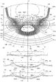
- FIG. 2A is an enlarged view of the vicinity of the embossed portion 9, and contour lines are attached to clarify the undulating state.
- the contour lines are drawn at predetermined height intervals with the ground contact surface of the annular chuck wall radius 3 as a horizontal plane, for example.
- the distance from the first panel surface 21 to the bottom surface 91 of the embossed portion 9 is 1.1 mm ⁇ 0.4 mm, 1.1 mm, and the number of contour line intervals is 17.
- the embossed portion 9 is provided on the second panel surface 22 with a predetermined depth, and includes a flat bottom surface 91 and an inner peripheral wall 92 surrounding the bottom surface 91.
- the shape of the bottom surface 91 is a trapezoidal shape symmetrical with respect to the second center line N, the first side 91a on the side opposite to the panel center O (panel peripheral side), the second side 91b on the panel center O side, It has a pair of side sides 91c and 91c connecting both ends of the first side 91a and both ends of the second side 91b.
- the first side 91a and the side sides 91c and 91c swell in an arc shape, and
- the two sides 91b are linear with respect to the second center line N.
- the corners of the first side 91a and the side side 91c are rounded.
- the inner peripheral wall 92 of the embossed portion 9 is inclined in a direction extending upward, a first inclined surface 92a located on the opposite side of the panel center O, a second inclined surface 92b on the can lid center side, and a first inclined surface It has side slopes 92c and 92c that connect both ends of 92a and both ends of the second slope 92b.
- the schematic shape of the outer peripheral edge of the inner peripheral wall 92 has a fan shape in which the outer peripheral edge of the first inclined surface 92a is an arc of a fan and the tip of the second inclined surface 92b is the center of the fan.
- the pair of side slopes 92c, 92c are inclined toward the panel center O side in a direction gradually approaching each other in line symmetry with respect to the second center line N.
- the first inclined surface 92 a and the side inclined surfaces 92 c and 92 c are inclined surfaces whose upper edges continue to the first panel surface 21, and the second inclined surfaces 92 b are inclined surfaces whose upper edges continue to the second panel surface 22. ing.
- the step portion 22b branches from the side slope 92c and bypasses the dimple 30 at a position where the side slope 92c, 92c transitions to the second slope 92b.
- the detour portion 22 b 1 of the step portion 22 b is continuous with the slope region 30 b on the side facing the tab 10 of the dimple 30 and constitutes a part of the slope of the dimple 30.
- the lower two thirds of the side slope 92c continues to the second slope 92b.
- the branch position between the second slope 92b and the stepped portion 22b is in the vicinity of the virtual branch line L passing through the linear second side 91b of the bottom surface 91, and the panel center O side of the inner peripheral wall 92 relative to the virtual branch line L.
- This region is defined as a second slope 92b.
- the contour line of the second slope 92b is a concave curve toward the bottom surface 91 when viewed from the second panel surface 22, and is recessed in a valley shape with a portion along the second center line N as a valley bottom. Is shown.
- the second inclined surface 92b extends toward the panel center O to a position facing at least the back surface of the finger hooking portion 13. In this embodiment, the entire second inclined surface 92b is guided for fingertip guidance according to the present invention. A recess is formed, and the side slope 92c is also a part of the guide recess.
- an imaginary line K, K that passes through both ends of the second side 91b of the bottom surface 91 and is parallel to the second center line N is drawn, and an area between the second inclined surface 92b and the imaginary lines K, K is a central area.
- the regions 92b1 and the virtual lines K, K that are located on the opposite side of the central region 92b1 and connected to the side slopes 92c, 92c are referred to as transition regions 92b2, 92b2.
- the outer edge of the second inclined surface 92b is the second contour line b1 viewed from the second panel surface 22 side, and the first contour line b0 located outside the second contour line b1 is a slight part of the second panel surface 22. It shows an inclination. If the contour line drawn toward the bottom surface including the contour line b1 is bn, each contour line bn is axisymmetric with respect to the second center line N in the central region 92b1 and has a convex arc shape toward the panel center O.
- the curved portion bn1 is curved, and the transition region 92b2 has diagonal portions bn2 and bn2 extending from both ends of the curved portion bn1 toward the side slopes 92c and 92c.
- the hatched portions bn2 and bn2 are inclined with respect to the second center line N so as to be inclined toward the panel center O in a direction in which the interval becomes narrower.
- the hatched portions bn2 and bn2 are slightly curved outward (in the opposite direction to the second center line N) and are smoothly continuous with the contour lines c2 and c2 of the side slopes 92c and 92c.
- the connecting portion between the hatched portions bn2 and bn2 and the curved portion bn1 is also smoothly continuous.
- the contour b1 has a concave arc connecting portion b13 on the outer side (opposite direction to the second center line N). Connected smoothly through.
- the interval between the curved portions bn1 of the contour lines bn in the central region 92b1 is substantially constant from the bottom surface 91 to a predetermined height, and the interval increases as the second panel surface 22 is approached.
- the interval between the curved portions bn1 on the bottom side is as wide as about twice the interval between the contour lines on the first inclined surface 92a side. Therefore, the inclination angle along the second center line N of the second inclined surface 92b is a gentle constant angle smaller than the inclination angle of the first inclined surface 92a from the bottom surface 91 to a predetermined height, and further the second panel. Up to the surface, the inclination angle gradually becomes gentle, and the second panel surface 22 is smoothly connected.
- the inclination angle along the second center line N of the second inclined surface 92b located on the rear end 13a side of the finger hook portion 13 is preferably set to an angle of 5 ° to 22 ° with respect to the bottom surface 91.
- This inclination angle is an angle of a straight line portion from the bottom surface 91 to a position where the second inclined surface 92b shown in the cross-sectional view of FIG. 2B to 2D are cross-sectional views in which the second inclined surface 92b is cut in a direction orthogonal to the second center line N.
- FIG. FIG. 2D shows a cut surface cut at the position of the second side 91b of the bottom surface 91.
- the central region 92b1 is linear, and the transition regions 92b2 and 92b2 are linear inclined sides.
- the opening width of the second slope 92b on the second panel surface 22 and the width between the upper ends of the inclined sides of the transition regions 92b2 and 92b2 (width in the direction perpendicular to the second center line N) Wd in this cross section are the second slope 92b. Is the maximum width.
- FIG. 2C is a cut surface cut at the position of the top portion 30a of the dimple 30, and the central region 92b1 has an arc shape that is slightly curved downward, and the depth from the second panel surface 22 becomes shallower.
- the regions 92b2 and 92b2 are linear inclined sides.
- FIG. 2B is a cut surface cut near the tip of the central region 92b1. At this position, there is no transition region, and the opening width (width in the direction orthogonal to the second center line N) Wb on the second panel surface 22 is further narrower than Wc.
- the dimples 30 are provided on the first panel surface 21 so as to protrude upward. If it is provided on the first panel surface 21, it is possible to suppress a reduction in the plate thickness when the dimple 30 is formed, which is more advantageous in terms of formability than that provided on the second panel surface 22. Moreover, the coating film coated on the surface is not damaged by excessive stretching.
- the dimples 30 and 30 are disposed in the vicinity of the corner portions 13c and 13c of the tab 10, and are basically provided for preventing an unexpected opening when the cans are stacked. Then, it has a fingertip guidance function.
- the distance A between the top portions 30a and 30a of the dimples 30 and 30 in the direction orthogonal to the second center line N is set to a range of 13 mm ⁇ 2 mm.
- the distance A between the top portions 30a and 30a is the distance between the highest points 30a and 30a (see FIG. 2C).
- the dimples 30 and 30 may have a trapezoidal shape with a flat top, and in this case, the dimples 30 and 30 have a minimum distance in the direction orthogonal to the second center line N between the peripheral edges of the top surface.
- the distance A between the top portions 30a and 30a of the dimples 30 and 30 is the width of the second fingernail central finger in the “Japanese hand dimension data” supervised by AIST (National Institute of Advanced Industrial Science and Technology). N12, male and female average (M + F): set based on 13.3 mm. Since this data is the width of the finger at the intermediate position from the nail edge to the tip of the finger, in this embodiment, the data is set slightly smaller in consideration of the fact that the fingertip is thinner than the intermediate position.
- the planar shape of the base portion is a rounded triangular shape with three sides bulging outward, and the middle part gradually transitions to a circular shape toward the apex.
- the top portion 30a is shifted to the detour portion 22b1 side of the step portion 22b, and is arranged close to the corner portion 13c of the tab 10.
- the slope region 30b facing the corner portion 13c of the tab 10 is located in the bypass portion 22b1 of the step portion 22b, and the bypass portion 22b1 is continuous with the slope region 30b of the dimple 30 and constitutes a part of the slope of the dimple 30.
- the detour portion 22b1 that expands toward the second panel surface 22 protrudes so as to overlap the back surface side of the corner portion 13c of the tab 10.
- the slope region 30 c facing the side slope 92 c of the embossed portion 9 of the dimple 30 is an inclined surface that is continuous with the side slope 92 c of the embossed portion 9.
- action of the can lid of this embodiment is demonstrated.
- the opening operation first, the fingertip is put into the embossed portion 9 and the fingertip is hung on the rear end 13a of the finger hooking portion 13 of the tab 10 (see FIGS. 3A and 4A).
- FIG. 4D the operation of the side inclined surfaces 92c and 92c until the fingertip is guided from the bottom surface of the embossed portion 9 to the second inclined surface 92b will be described.
- the side slopes 92c and 92c and the slope regions 30c and 30c of the dimples 30 and 30 that are continuous with the side slopes 92c and 92c are hatched in a diagonal lattice pattern, and the slopes 30c and 92c are continuous from the side slopes 92c and 92c.
- the transition areas 92b2 and 92b2 of the two inclined surfaces 92b are obliquely hatched.
- the hatched portions in the vertical and horizontal lattice shapes schematically show the region of the contact portion S where the fingertip portion in FIG. In the initial stage, the abutting portion S moves from the bottom surface 91 toward the second inclined surface 92b.
- the abutting portion S is, for example, one side from the second center line N as shown by S1 in the drawing. Even if it is shifted to the side slope 92c side, the side slope 92c is inclined in the direction approaching the second center line N toward the panel center. , Moving toward the second inclined surface 92b while correcting the deviation in the direction approaching the second center line N, directed to the direction along the second center line N, that is, the direction toward the panel center O, and Even after reaching the second slope 92b, it is continuously guided by the transition regions 92b2 and 92b2 of the second slope 92b that continues to the side slope 92c.
- the inclined region 30c of the dimple 30 facing the side inclined surface 92c is an inclined surface continuous with the side inclined surface 92c of the embossed portion 9, and not only the contact portion S of the fingertip, Since the movement of the fingertip side surface in the direction away from the second centerline N is restricted by the slope regions 30c and 30c of the dimples 30 and 30, the movement direction of the fingertip is more effectively changed to the second centerline N Can be guided in the direction along Next, as shown in FIG. 3B, the tab 10 is raised upward. As shown in FIGS.
- the fingertip portion has an inclined surface of the central region 92b1 of the valley-shaped second inclined surface 92b from the bottom surface 91 of the embossed portion 9 at the second center. It is guided along the line N to the center in the width direction of the back surface of the finger hook portion 13 (see FIGS. 4B and 4C). That is, in the second slope 92b, the central region 92b1 is deeper than the left and right transition regions 92b2 and 92b2, and the fingertip is automatically positioned deeper in the central region 92b1 due to the reaction force acting on the fingertip from the tab 10. Be guided.
- the opening width of the second slope 92b in the second panel surface 22 is wide on the bottom face 91 side of the embossed portion 9, and the panel center. Since the width gradually decreases toward O, the finger is naturally guided to the center in the width direction on the back surface of the finger hook portion 13. Further, since the central region 92b1 that becomes the valley bottom of the second inclined surface 92b is a gently inclined surface along the second center line N toward the panel center O, the tab 10 is gradually lifted as the fingertip is gradually lifted. Is caused.
- the distance A between the dimples 30 and 30 is set to about 13 mm, while the fingertip is guided by the second inclined surface 92b, it passes between the left and right dimples 30 and 30. Instead, the fingertip is guided to the central region 92b1 of the second inclined surface 92b from the fingering stage. In this way, at the initial stage of placing the finger on the rear end of the finger hook portion 13 and causing the tab 10, the trajectory of the fingertip along the second center line N is caused by the second inclined surface 92 b on the back surface of the finger hook portion 13.
- the direction of the force is not greatly deviated obliquely from the direction of the panel center O in the subsequent raising operation, and the starting force is applied to the starting point of the score near the rivet portion 7 through the tab tip 11. It is possible to concentrate the action on the part 6a and break the score 6.
- the can lid of the present invention can be used for both negative pressure cans and positive pressure cans, and is not limited to positive pressure cans.
- the height h of the dimple 30 is a height from the second panel 22 that is one step lower than the first panel 21, as shown in FIGS. The higher the dimple 30 is, the less likely it is to catch on the upper can bottom leg.
- the thickness is preferably 0.5 mm or more and 1.2 mm or less from the viewpoint of preventing unexpected opening and the formability. More preferably, it is 0.5 mm or more and 1.2 mm or less, more preferably 0.8 mm or more and 1.2 mm or less.
- FIG. 5 (A) shows a first type can body 200
- FIG. 5 (B) shows a second type can body 300, each showing a state of being stacked in two stages.
- the reference numeral 100 is attached to the can lid.
- the first-type can body 200 is a two-piece can as shown in FIG. 5A, and the can lid 100 is fastened and fixed to the opening end of the body portion 204 to form a tightening portion 205.
- the can bottom 201 has a dome portion 202 that is recessed inwardly toward the inside of the can, and an annular first shape leg portion 203 that protrudes downward from the outer peripheral edge of the dome portion 202, and the positive pressure can is moved up and down.
- the first shape leg 203 of the can bottom 201 of the upper can is placed at a position close to the finger hook 13 of the tab 10 of the can lid 100 of the lower can.
- the inner peripheral surface 203a of the first shape leg 203 is an inclined surface that is inclined in a direction in which the diameter becomes smaller toward the inside of the can. Further, the outer peripheral surface 203b of the first shape leg portion 203 is inclined in a direction of gradually increasing the diameter upward.
- the second-type can body 200 is also a two-piece can as shown in FIG. 5B, and the can lid 100 is fastened and fixed to the open end of the body portion 304 to form a tightening portion 305.
- the can bottom 301 also has a dome portion 302 that is recessed inwardly toward the inside of the can, and an annular second-shaped leg portion that projects downward from the outer peripheral edge of the dome portion 302. 303, and when the cans are stacked up and down, the second-shaped leg portion 303 of the can bottom 301 of the upper can is placed at a position close to the finger hook portion of the tab of the can lid 100 of the lower can. Placed.
- the leg portion 303 having the second shape is called a bottom reform shape.
- the second can body 300 has an inclined surface in which the inner peripheral surface 303a of the second shape leg portion 303 is inclined in a direction in which the inner diameter surface 303a becomes larger in the radial direction (in the expanding direction).
- the second shaped leg 303 of the upper can bottom 301 is more easily hooked by the tab of the can lid 100 of the lower can body than the can body 200 of the seed.
- FIG. 6 is an enlarged cross-sectional view of a main part of the loading portion of the first can body 200 in FIG. 5A, and the leg portion 203 having the first shape in a normally loaded state is inclined along a two-dot chain line.
- the first-shaped leg 203 in the state of being in a state is shown by a solid line.
- the cross section is a view cut at the corner 13c of the tab 10.
- the lower end portion 203c of the first shape leg 203 having an arc cross section is in contact with the first panel surface of the can lid 100 of the lower can, and The outer peripheral surface 203b of the first shape leg 203 is placed in contact with the upper end of the lower can winding part 205.
- the upper can is tilted, as shown by the solid line, it rides on the outer peripheral surface 203b of the first shape leg portion 203 and the winding fastening portion 205, and the lower end portion 203c having an arcuate cross section rides on the dimple 30 and The corner portion 13c of the hanging portion 13 is contacted.
- the leg 203 moves in the direction of lifting the tab 10 upward, and if the hook is strong, a sudden opening will occur due to the lever action.
- FIG. 7 is an enlarged view of a main part of the loading portion of the second can 300 in FIG. 5B, and the first shape leg 303 in a normally loaded state is tilted by a two-dot chain line.
- the second shape leg 303 in the state is indicated by a solid line.
- the cross section is a view cut at the corner 13c of the tab 10.
- the lower end portion 303c of the second shape leg portion 303 having a circular arc cross section contacts the first panel surface of the can lid 100 of the lower can, and
- the outer peripheral surface 303b of the second-shaped leg portion 303 is placed in contact with the upper end of the lower can lid winding fastening portion 305.
- the upper can when tilted, as shown by the solid line, it rides on the outer peripheral surface 303b of the second shape leg portion 303 and the winding fastening portion 305, and the lower end portion 303c having an arcuate cross section rides on the dimple 30 and The corner portion 13c of the hanging portion 13 is contacted.
- the height of the dimple 30 of the above-described four types of can lids was set to four types of 0.7 mm, 0.8 mm, 1.0 mm, and 1.2 mm.
- the diameter of the can lid 100 was 57.15 mm, the plate thickness was 0.235 mm, and the internal pressure was set to 200 kPa at normal temperature for both the first can body 200 and the second can body 300.
- the can lid 100 bulges outward due to the internal pressure, the tab 10 is lifted from the second panel surface 22, and the gap from the lifted second panel surface 22 is about 2.3 mm.
- the evaluation object can bodies (positive pressure) filled with the contents were stacked in two upper and lower stages, and the first can body 200 and the second can body 300 were When the leg part of the sword was tilted by hand in the direction of catching on the tab, the presence or absence of catching was relatively evaluated, and the evaluation results were evaluated in three stages, ⁇ , ⁇ , and ⁇ .
- the evaluation stage is as follows. A: There is no catch between the leg of the can bottom and the tab, and no unexpected opening occurs. ⁇ : Slightly feels catching between the bottom of the can bottom and the tab, but there is no unexpected opening.
- the formability is 0.7 mm, 0.8 mm, and 1.0 mm, all of which are “ ⁇ ”, and the decrease in thickness is negligible.
- the evaluation was appropriate. Further, at 1.2 mm, the plate thickness was slightly reduced, and the evaluation was practical.
- the slope on the rear end side of the finger hook portion of the embossed portion is for fingertip guidance extending to a position facing at least the center portion in the width direction of the back surface of the finger hook portion toward the center of the can lid.
- the structure is provided with a guide recess, there is no guide recess and only dimples may be provided. The range of movement of the finger in the short-side direction of the tab is limited by the pair of dimples, so that the fingertip is guided to the center in the width direction of the finger hook portion, and the tab is easily directed toward the center of the lid.
- the finger hook part 13 is formed in linear form, you may provide the tip up part of a step shape or an arch shape in the width direction center part of the finger hook part 13.
- the hole 14 is provided in the tab 10, the hole 14 does not need to be provided.
- the center panel 2 was set as the structure which has the 1st panel surface 21 and the 2nd panel surface 22 lower than a 1st panel surface, the 2nd panel surface 22 does not need to be.
- the rivet portion 7 is provided at the center of the panel of the center panel. However, the rivet portion 7 does not have to be at the panel center position, and the rivet portion 7 may be shifted from the center of the panel on the second center line.
Landscapes
- Engineering & Computer Science (AREA)
- Mechanical Engineering (AREA)
- Containers Opened By Tearing Frangible Portions (AREA)
Abstract
Priority Applications (5)
| Application Number | Priority Date | Filing Date | Title |
|---|---|---|---|
| JP2020512293A JP7472785B2 (ja) | 2018-04-03 | 2019-04-03 | 缶蓋 |
| US17/044,556 US11560255B2 (en) | 2018-04-03 | 2019-04-03 | Can lid |
| EP19780785.2A EP3778414A4 (fr) | 2019-04-03 | Couvercle de canette | |
| CN201980024125.9A CN112074463B (zh) | 2018-04-03 | 2019-04-03 | 罐盖 |
| KR1020207029147A KR102516439B1 (ko) | 2018-04-03 | 2019-04-03 | 캔 뚜껑 |
Applications Claiming Priority (2)
| Application Number | Priority Date | Filing Date | Title |
|---|---|---|---|
| JP2018071631 | 2018-04-03 | ||
| JP2018-071631 | 2018-04-03 |
Publications (1)
| Publication Number | Publication Date |
|---|---|
| WO2019194237A1 true WO2019194237A1 (fr) | 2019-10-10 |
Family
ID=68100538
Family Applications (1)
| Application Number | Title | Priority Date | Filing Date |
|---|---|---|---|
| PCT/JP2019/014849 Ceased WO2019194237A1 (fr) | 2018-04-03 | 2019-04-03 | Couvercle de canette |
Country Status (5)
| Country | Link |
|---|---|
| US (1) | US11560255B2 (fr) |
| JP (1) | JP7472785B2 (fr) |
| KR (1) | KR102516439B1 (fr) |
| CN (1) | CN112074463B (fr) |
| WO (1) | WO2019194237A1 (fr) |
Cited By (1)
| Publication number | Priority date | Publication date | Assignee | Title |
|---|---|---|---|---|
| US20220144485A1 (en) * | 2020-11-11 | 2022-05-12 | Easytech Closures S.p.A. | Removable closure device for metal containers |
Families Citing this family (3)
| Publication number | Priority date | Publication date | Assignee | Title |
|---|---|---|---|---|
| US20210101724A1 (en) * | 2019-10-04 | 2021-04-08 | Robert E Markus | Lid for beverage cans |
| USD988126S1 (en) * | 2022-06-14 | 2023-06-06 | Meirong Lv | Bottle lid |
| US20240216981A1 (en) * | 2023-01-02 | 2024-07-04 | Mitchell Everts | Pull Tab With Improved Accessibility And Associated Methods Of Manufacture |
Citations (6)
| Publication number | Priority date | Publication date | Assignee | Title |
|---|---|---|---|---|
| JPS5741198B2 (fr) | 1977-02-25 | 1982-09-01 | ||
| JPH0910874A (ja) * | 1995-06-27 | 1997-01-14 | Mitsubishi Materials Corp | 簡易開口缶蓋 |
| JP2010070225A (ja) * | 2008-09-19 | 2010-04-02 | Daiwa Can Co Ltd | 開口容易缶蓋 |
| JP2012236624A (ja) * | 2011-05-11 | 2012-12-06 | Toyo Seikan Kaisha Ltd | 缶蓋 |
| JP2015071436A (ja) * | 2013-10-02 | 2015-04-16 | 大和製罐株式会社 | 缶蓋 |
| JP2015085962A (ja) * | 2013-10-31 | 2015-05-07 | 大和製罐株式会社 | 缶蓋 |
Family Cites Families (16)
| Publication number | Priority date | Publication date | Assignee | Title |
|---|---|---|---|---|
| US4276993A (en) * | 1979-10-10 | 1981-07-07 | The Continental Group, Inc. | Easy-opening container with non-detach tab |
| JPS5812144U (ja) * | 1981-07-16 | 1983-01-26 | 東洋製罐株式会社 | 開口容易な缶蓋 |
| KR0168052B1 (ko) * | 1990-11-28 | 1998-12-01 | 타카사끼 요시로오 | 따기 쉬운 캔뚜껑 및 그 제조방법 |
| JP2568795B2 (ja) * | 1992-11-18 | 1997-01-08 | 食品産業エコロジカル・パッキング技術研究組合 | イージーオープン缶蓋 |
| JP2001018960A (ja) * | 1999-07-01 | 2001-01-23 | Hokkai Can Co Ltd | ステイオンタブ式缶蓋 |
| DE10261232A1 (de) * | 2002-12-20 | 2004-07-22 | Wichelhaus, André | Verschluss für einen Behälter |
| JP4490847B2 (ja) * | 2005-02-23 | 2010-06-30 | サントリーホールディングス株式会社 | 缶蓋及びこれを備えた缶容器 |
| JP5588259B2 (ja) | 2010-07-29 | 2014-09-10 | ユニバーサル製缶株式会社 | 缶蓋 |
| US8695245B2 (en) * | 2011-11-28 | 2014-04-15 | Christopher P. Schorre | Wing shaped beverage can pull tab |
| ES2574903T3 (es) * | 2011-12-20 | 2016-06-23 | Ardagh Mp Group Netherlands B.V. | Panel y recipiente provisto de dicho panel |
| CN104136335B (zh) * | 2012-04-25 | 2017-05-17 | 昭和铝罐株式会社 | 罐盖及饮料罐 |
| US9181007B2 (en) * | 2013-03-12 | 2015-11-10 | Rexam Beverage Can Company | Beverage can end with vent port |
| US9033174B2 (en) * | 2013-03-15 | 2015-05-19 | Ball Corporation | Easy access opening tab for a container end closure |
| KR20160000801U (ko) * | 2014-09-01 | 2016-03-09 | 장기원 | 개량형 캔 뚜껑 |
| JP6953022B2 (ja) * | 2016-02-29 | 2021-10-27 | パワーキャン ホールディング, エルエルシーPowercan Holding, Llc | 再封式容器蓋および付属品ならびにその製造方法と使用方法 |
| JP2017214103A (ja) * | 2016-05-31 | 2017-12-07 | 東洋製罐株式会社 | 缶蓋のタブ |
-
2019
- 2019-04-03 WO PCT/JP2019/014849 patent/WO2019194237A1/fr not_active Ceased
- 2019-04-03 CN CN201980024125.9A patent/CN112074463B/zh active Active
- 2019-04-03 US US17/044,556 patent/US11560255B2/en active Active
- 2019-04-03 JP JP2020512293A patent/JP7472785B2/ja active Active
- 2019-04-03 KR KR1020207029147A patent/KR102516439B1/ko active Active
Patent Citations (6)
| Publication number | Priority date | Publication date | Assignee | Title |
|---|---|---|---|---|
| JPS5741198B2 (fr) | 1977-02-25 | 1982-09-01 | ||
| JPH0910874A (ja) * | 1995-06-27 | 1997-01-14 | Mitsubishi Materials Corp | 簡易開口缶蓋 |
| JP2010070225A (ja) * | 2008-09-19 | 2010-04-02 | Daiwa Can Co Ltd | 開口容易缶蓋 |
| JP2012236624A (ja) * | 2011-05-11 | 2012-12-06 | Toyo Seikan Kaisha Ltd | 缶蓋 |
| JP2015071436A (ja) * | 2013-10-02 | 2015-04-16 | 大和製罐株式会社 | 缶蓋 |
| JP2015085962A (ja) * | 2013-10-31 | 2015-05-07 | 大和製罐株式会社 | 缶蓋 |
Cited By (1)
| Publication number | Priority date | Publication date | Assignee | Title |
|---|---|---|---|---|
| US20220144485A1 (en) * | 2020-11-11 | 2022-05-12 | Easytech Closures S.p.A. | Removable closure device for metal containers |
Also Published As
| Publication number | Publication date |
|---|---|
| JP7472785B2 (ja) | 2024-04-23 |
| KR20200127249A (ko) | 2020-11-10 |
| CN112074463B (zh) | 2022-09-23 |
| CN112074463A (zh) | 2020-12-11 |
| EP3778414A1 (fr) | 2021-02-17 |
| US11560255B2 (en) | 2023-01-24 |
| JPWO2019194237A1 (ja) | 2021-04-08 |
| US20210155371A1 (en) | 2021-05-27 |
| KR102516439B1 (ko) | 2023-03-30 |
Similar Documents
| Publication | Publication Date | Title |
|---|---|---|
| WO2019194237A1 (fr) | Couvercle de canette | |
| JP6703368B2 (ja) | パネル、ならびにそのようなパネルが設けられる容器本体および容器 | |
| JP4979128B2 (ja) | 開口容易缶蓋 | |
| JP2003054549A (ja) | 簡易開口缶蓋 | |
| JP7540135B2 (ja) | 缶蓋 | |
| WO2006090525A1 (fr) | Couvercle de boite de conserve et recipient en forme de boite de conserve equipe de celui-ci | |
| JP6779043B2 (ja) | 開缶用タブ及び缶蓋並びに缶、開缶用タブの製造方法 | |
| JP5741198B2 (ja) | 缶蓋 | |
| JP7590782B2 (ja) | プラスチック容器 | |
| JP4879802B2 (ja) | 缶蓋及び缶蓋の製造方法 | |
| JP2000128168A (ja) | フルオープン缶蓋 | |
| JP5246858B2 (ja) | 開口容易缶蓋 | |
| JP2024052247A (ja) | 缶蓋 | |
| JP2005162267A (ja) | 開口容易蓋のタブ | |
| US6793089B1 (en) | Can with improved opening structure | |
| JP4424626B1 (ja) | プルトップ | |
| JP4895573B2 (ja) | 開口容易缶蓋のタブおよびタブの成形方法 | |
| JP7674086B2 (ja) | 包装用容器の蓋体 | |
| JP7585753B2 (ja) | 缶蓋 | |
| JP4521762B2 (ja) | 開口容易缶蓋 | |
| JP5864982B2 (ja) | 缶蓋 | |
| JP2017030849A (ja) | 缶蓋 | |
| JP3467647B2 (ja) | 収納ケース | |
| JP5189660B2 (ja) | 二重テコ式プルタブ構造を有する缶 | |
| JP2024078243A (ja) | プラスチック容器 |
Legal Events
| Date | Code | Title | Description |
|---|---|---|---|
| 121 | Ep: the epo has been informed by wipo that ep was designated in this application |
Ref document number: 19780785 Country of ref document: EP Kind code of ref document: A1 |
|
| ENP | Entry into the national phase |
Ref document number: 2020512293 Country of ref document: JP Kind code of ref document: A |
|
| NENP | Non-entry into the national phase |
Ref country code: DE |
|
| ENP | Entry into the national phase |
Ref document number: 20207029147 Country of ref document: KR Kind code of ref document: A |
|
| ENP | Entry into the national phase |
Ref document number: 2019780785 Country of ref document: EP Effective date: 20201103 |
|
| WWW | Wipo information: withdrawn in national office |
Ref document number: 2019780785 Country of ref document: EP |