WO2019202648A1 - Dispositif de détection de diffusion de lumière - Google Patents
Dispositif de détection de diffusion de lumière Download PDFInfo
- Publication number
- WO2019202648A1 WO2019202648A1 PCT/JP2018/015769 JP2018015769W WO2019202648A1 WO 2019202648 A1 WO2019202648 A1 WO 2019202648A1 JP 2018015769 W JP2018015769 W JP 2018015769W WO 2019202648 A1 WO2019202648 A1 WO 2019202648A1
- Authority
- WO
- WIPO (PCT)
- Prior art keywords
- light
- sample cell
- scattering
- detector
- detection
- Prior art date
- Legal status (The legal status is an assumption and is not a legal conclusion. Google has not performed a legal analysis and makes no representation as to the accuracy of the status listed.)
- Ceased
Links
Images





Classifications
-
- G—PHYSICS
- G01—MEASURING; TESTING
- G01N—INVESTIGATING OR ANALYSING MATERIALS BY DETERMINING THEIR CHEMICAL OR PHYSICAL PROPERTIES
- G01N15/00—Investigating characteristics of particles; Investigating permeability, pore-volume or surface-area of porous materials
- G01N15/02—Investigating particle size or size distribution
-
- G—PHYSICS
- G01—MEASURING; TESTING
- G01N—INVESTIGATING OR ANALYSING MATERIALS BY DETERMINING THEIR CHEMICAL OR PHYSICAL PROPERTIES
- G01N21/00—Investigating or analysing materials by the use of optical means, i.e. using sub-millimetre waves, infrared, visible or ultraviolet light
- G01N21/17—Systems in which incident light is modified in accordance with the properties of the material investigated
- G01N21/47—Scattering, i.e. diffuse reflection
- G01N21/49—Scattering, i.e. diffuse reflection within a body or fluid
Definitions
- the present invention relates to a light scattering detection device used for a particle detection device for measuring the molecular weight, the radius of rotation (size), etc., of particles dispersed in a liquid sample.
- SEC size exclusion chromatography
- GPC gel filtration chromatography
- MALS multi-angle light scattering
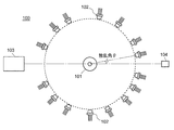
- the MALS detection apparatus 100 includes a cell 101 that holds a liquid sample, a plurality of detectors 102, a light source 103 that makes visible laser light incident on the sample cell 101, and a beam damper 104 that absorbs the laser light.
- the sample cell 101 is usually a cylindrical cell, and light from the light source 103 is incident on the sample cell 101 from the vertical direction.
- the cell 101 is centered on the same plane passing through the optical axis of the light from the light source 103 so that the light emitted from the sample (cell) with a plurality of different scattering angles can be detected simultaneously.
- a plurality of detectors 102 are arranged to surround Then, the relationship between the scattered light intensity and the scattering angle ⁇ is obtained from the scattered light intensities obtained by the plurality of detectors 102, and the molecular weight and size (rotation radius) of the fine particles in the sample are calculated from this relationship.
- the MALS detector is required to measure the scattered light of a sample having a lower concentration or a sample containing fine particles having a smaller particle diameter with high sensitivity. Since the intensity of scattered light generated from a low-concentration sample or small particle sample is low, the solid angle of light incident on each detector is made as large as possible to increase the scattered light generated from the sample. It must be incident on the detector with efficiency. In particular, since the scattered light intensity is proportional to the sixth power of the particle diameter, it is important to increase the solid angle of the scattered light incident on the detector when detecting scattered light of a particle having a small particle diameter.
- the problem to be solved by the present invention is to be able to measure scattered light intensity with high angular resolution and high sensitivity.
- the present invention made to solve the above problems is a light scattering detection device for detecting fine particles in a liquid sample, a) a transparent sample cell holding a liquid sample; b) a light source for irradiating the sample cell with coherent light; c) a plurality of first detectors arranged so as to surround the sample cell and detecting light scattered around the sample cell with different scattering angles in response to the irradiation of the coherent light; and the sample cell And first imaging means disposed between each of the first detectors and an imaging lens for imaging light scattered from the sample cell on a light receiving surface of the first detector; d) Second detection having a second detector in which a plurality of detection elements are arranged in an array to detect light scattered from the sample cell with a scattering angle in a predetermined angular range in response to the irradiation of the coherent light.
- the predetermined angle range is an angle range included in a range from 0 ° to ⁇ 90 °.
- the coherent light is desirably light with high spatial coherence, and is typically laser light.
- the first detector include a single element sensor such as a photodiode, a phototransistor, and a photomultiplier tube.
- the second detector include a two-dimensional CMOS image sensor, a one-dimensional photodiode array sensor, and a CCD image sensor.
- Array sensors Moreover, you may comprise both the 1st detector and the 2nd detector from the array sensor by which a some detection element is arranged in the array form.
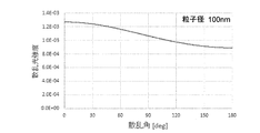
- FIGS. 8A to 8C show the relationship between the intensity of scattered light and the scattering angle emitted from a liquid sample containing fine particles having particle diameters of 10 nm, 100 nm, and 1000 nm, respectively, when irradiated with light having a wavelength of 650 nm. ing.
- the refractive index of the solvent of each liquid sample is 1.3, and the refractive index of the liquid sample is 1.6.
- the intensity of the scattered light depends on the particle size of the fine particles contained in the sample.
- the intensity of the scattered light when the scattering angle is 0 ° is proportional to the sixth power of the particle diameter.
- the light scattering detection apparatus having the above configuration, light scattered from the sample cell with various scattering angles is incident on the plurality of first detectors constituting the first detection means through the imaging lens to constitute the second detection means.
- the light scattered in a predetermined angle range included in the range from 0 ° to ⁇ 90 ° from the sample cell is incident on the second detector.
- the scattering angle of light scattered on one side of the straight line connecting the optical path of the coherent light from the light source and the sample cell is “+”, and the scattering angle of light scattered on the other side is “ ⁇ ”.
- the scattered light from the sample cell is made incident on the first detector through the imaging lens, so that the number of the first detectors is reduced, but a large detection solid angle can be realized, and the sensitivity. Can be measured with high sensitivity.
- the second detection means it is possible to continuously measure the intensity of scattered light in the above-mentioned angular range, and it is possible to accurately measure fine particles having a large particle diameter in which scattered light increases forward from the sample cell.
- the second detection unit includes an aperture disposed between the second detector and the sample cell, and a collimating lens that collimates the light that has passed through the aperture. .
- the second detection unit includes an aperture disposed between the second detector and the sample cell, and a collimating lens that collimates the light that has passed through the aperture.
- the second detection unit further includes a relay lens disposed between the aperture and the sample cell, and the aperture is disposed at a conjugate point of the relay lens.
- the aperture is disposed at a conjugate point of the relay lens.
- the second detection means includes one or two second detectors,
- the predetermined angle range may be an angle range included in a range from 0 ° to ⁇ 30 °.
- FIG. 8C in the case of a particle having a particle diameter of 1000 nm, the intensity of the scattered light is significantly reduced when the scattering angle is 30 ° or more. Therefore, it is necessary to detect the scattered light at a plurality of locations where the scattering angle is 30 ° or less. There is. According to the above configuration, scattered light caused by large fine particles having a particle diameter exceeding 1000 nm can be measured with high angular resolution.
- the first detection means further includes the light scattered between the sample cell and the imaging lens and scattered from the sample cell with a scattering angle outside a predetermined angle range. It is preferable to provide a slit that restricts incidence to the image lens.
- the first detection means may have an aperture arranged between the first detector and the imaging lens for extracting the scattered light image of the sample cell.
- the imaging lens of the first detection means may be constituted by a cylindrical lens. In this configuration, only a light beam in a predetermined direction can be incident on the first detector.
- the second detection means includes a cylindrical lens disposed between the collimating lens and the second detector. In this configuration, only a light beam in a predetermined direction can be incident on the second detector.
- the optical axis of coherent light incident on the sample cell from the light source is inclined at a predetermined angle from a plane including the center of the light receiving surface of the first detector and the center of the light receiving surface of the second detector. It is preferable to arrange the light source. According to this configuration, when the coherent light from the light source is incident on the sample cell, the reflected light generated at the interface between the sample cell and the air and at the interface between the sample cell and the liquid sample is the first detector and the second detector. The amount of incident light can be reduced.
- the plurality of first detectors of the first detection means are arranged so as to surround the sample cell, and the second of the second detection means is at a location where light scattered from the sample cell with a relatively small scattering angle is incident.
- a detector was placed.
- an imaging lens is arranged between the sample cell and each first detector, and in the second detection means, a detector in which a plurality of detection elements are arranged in an array is provided. Since the detector is used, the scattered light intensity at various scattering angles can be measured with high sensitivity, and the scattered light caused by fine particles having a large particle diameter can be measured with high angular resolution.
- FIG. 1 is a schematic plan view showing an embodiment of a light scattering detection device according to the present invention.
- the top view which expands and shows a part of 1st and 2nd detection optical system in the light-scattering detection apparatus shown in FIG.
- the top view which shows the modification of the 2nd detection optical system of the light-scattering detection apparatus which concerns on this invention.
- the side view which shows the modification of the 2nd detection optical system of the light-scattering detection apparatus which concerns on this invention.
- the schematic diagram of the modification of the light-scattering detection apparatus which concerns on this invention.
- the side view which shows the modification of the 1st detection optical system of the light-scattering detection apparatus which concerns on this invention.
- the top view which shows the basic composition of the conventional light-scattering detection apparatus.
- the side view which shows the basic composition of the conventional light-scattering detection apparatus.
- the graph which shows the relationship between the scattered light intensity
- the graph which shows the relationship between the scattered light intensity
- the graph which shows the relationship between the scattered light intensity
- the light scattering detection apparatus 1 includes a sample cell 10 in which a liquid sample is accommodated, a laser light source unit 20 for irradiating the sample cell 10 with laser light that is coherent light, and a sample cell 10.
- a sample cell 10 in which a liquid sample is accommodated
- a laser light source unit 20 for irradiating the sample cell 10 with laser light that is coherent light
- a sample cell 10 nine first detection optical systems 30 and two second detection optical systems 40, and first and second detection optical systems 30 and 40 for detecting scattered light generated by irradiating laser light on A data processing unit 50 for processing the obtained data.
- the first and second detection optical systems 30 and 40 correspond to the first and second detection means of the present invention
- the data processing unit 50 corresponds to the arithmetic processing means of the present invention.
- a plurality of detection optical systems including the first detection optical system 30 and the second detection optical system 40 are arranged so as to surround the sample cell 10 at the center. Specifically, it is on a horizontal plane including the optical path L1 of the laser light emitted from the laser light source unit 20 and directed to the sample cell 10 and its extension line L1 ′, and is on one side with respect to the optical path L1 and the extension line L1 ′. In the region (upper region in FIG. 1), four first detection optical systems 40 and one second detection optical system 40 are arranged, and in the other region (lower side in FIG. 1), 5 One first detection optical system 30 and one second detection optical system 40 are arranged.
- the sample cell 10 is composed of a cylindrical cell whose periphery is transparent.
- a condensing lens 21 made of a plano-convex lens is disposed on the optical path L1 between the laser light source unit 20 and the sample cell 10, and the laser light emitted from the laser light source unit 20 has passed through the condensing lens 21. Thereafter, the light is collected near the central axis of the sample cell 10.
- a laser damper 22 that absorbs laser light is disposed on the extension line L1 ′ of the optical path L1, that is, at a position where the laser light incident on the sample cell 10 from the laser light source unit 20 along the optical path L1 travels straight. .
- FIG. 2 is a schematic diagram showing the first detection optical system 30 and the second detection optical system 40 in an enlarged manner. In this figure, only one first detection optical system 30 and one second detection optical system 40 are drawn, and the other first and second detection optical systems 30 and 40 are omitted.
- the first detection optical system 30 includes a slit plate 301 having a scattering angle limiting slit, an imaging lens 302, and a photodiode 303.
- the slit of the slit plate 301 has a vertically long rectangular shape in order to limit the scattering angle in the horizontal direction and to capture a large amount of light flux in the vertical direction.
- the slit plate 301 and the imaging lens 302 are positioned so that the center of the slit of the slit plate 301 constituting each first detection optical system 30, the optical axis of the imaging lens 302, and the center of the light receiving surface of the photodiode 303 are located.
- the photodiodes 303 are arranged in order from the sample cell 10 side.
- the angle above the extension line L1 'of the optical path L1 shown in FIGS. 1 and 2 is represented by “+”, and the angle below is represented by “ ⁇ ”.
- the imaging lens 302 is a plano-convex lens, and the light receiving surface of the photodiode 303 is located at the focal point.
- the slit plate 301 has a slit size set so that all of the light beam that has passed through the slit is incident on the light receiving surface of the photodiode 303 by the imaging lens 302.
- the solid angle of the photodiode 303 is determined from the distance between the sample cell 10 and the slit plate 301 and the size of the slit of the slit plate 301.
- the second detection optical system 40 includes a relay lens 401, an aperture plate 402, a collimator lens 403, and an array detector 404 having a plurality of detection elements.
- the array detector 404 is composed of a two-dimensional CMOS detector.
- CMOS detector for example, DMK33GX174 manufactured by Imaging Source can be used.
- Detectors 404 are arranged in order from the sample cell 10 side.
- the relay lens 401 is configured by combining two doublet lenses.
- the relay lens 401, the aperture plate 402, and the collimating lens 403 are arranged so that the aperture of the aperture plate 402 is positioned at the conjugate point of the relay lens 401 and at the focal point of the collimating lens 403.
- the solid angle of the array detector 404 is determined from the distance between the sample cell 10 and the relay lens 401 and the outer diameter of the relay lens 401.
- the operation of the light scattering detector 1 will be described.
- laser light which is coherent light
- the laser light is emitted from the laser light source unit 20 and travels along the optical path L1
- the laser light is irradiated onto the sample in the sample cell 10
- the light hits the fine particles contained in the sample and is predetermined. It scatters with the scattering angle of.
- a part of the scattered light emitted from the sample cell 10 enters the first detection optical system 30, and a part enters the second detection optical system 40.
- the nine first detection optical systems 30 respectively receive scattered light having a scattering angle ⁇ range of + 10 ° to + 180 ° and ⁇ 10 ° to ⁇ 180 °.
- scattered light having a scattering angle ⁇ in the range of 0 ° to ⁇ 30 ° is incident on the two second detection optical systems 40, respectively.
- the scattered light that has entered each first detection optical system 30 passes through the slit of the slit plate 301 and then enters the light receiving surface of the photodiode 303 through the imaging lens 302. At this time, since all the light passing through the slit of the slit plate 301 is incident on the light receiving surface of the photodiode 303 by the imaging lens 302, the amount of light received by the photodiode 303 increases.
- the scattered light that has entered each second detection optical system 40 passes through the relay lens 401, so that the source of the scattered light (that is, the fine particles) forms an image at the conjugate point.
- the aperture of the aperture plate 402 is disposed at the conjugate point of the relay lens 401, unnecessary stray light is removed by the aperture, and only the scattered light from the sample is directed to the collimating lens 403, and the collimating lens 403 converts it into parallel light. Then, the light beams are incident on the plurality of detection elements of the array detector 404 in a dispersed manner.
- the data processing unit 50 reads the detection signals of the nine photodiodes 303 simultaneously, and the first particle information calculation unit 501 calculates the scattered light intensity at each angular position.
- the data processing unit 50 stores the concentration information of the liquid sample held in the sample cell 10 in advance, and the first particle information calculation unit 501 determines the scattered light intensity and the sample concentration at each angular position. Based on this, the molecular weight, rotation radius, etc. of the fine particles contained in the sample are calculated. This calculation itself is the same as that of a conventional light scattering detector.
- the data processing unit 50 reads the detection signal of each element of the two array detectors 404 and calculates the scattered light intensity at each angular position. Then, similarly to the first particle information calculation unit 501, the second particle information calculation unit 502 is based on the scattered light intensity at each angular position and the concentration of the sample, the molecular weight of the fine particles contained in the sample, the radius of rotation, etc. Calculate
- the scattered light emitted from the sample cell 10 is scattered light caused by relatively small fine particles having a particle diameter of 500 nm or less, the scattered light is dispersed over the entire periphery of the sample cell 10 and the particle diameter is 500 nm. If the scattered light is caused by fine particles having a relatively large particle diameter exceeding 1, the scattered light is biased and dispersed in front of the sample cell 10.
- the data processing unit 50 is included in the sample from the result calculated by the first particle information calculation unit 501.
- the molecular weight, rotation radius, etc. of the fine particles contained in the sample are obtained from the results calculated by the second particle information calculation unit 502.
- the intensity of the scattered light forward of the sample cell 10 can be detected with high angular resolution by the array detector 404, the molecular weight and rotation radius of the fine particles having a large particle diameter can be increased with high accuracy. Can be obtained.
- the provision of the second detection optical system 40 reduces the number of the first detection optical systems 30 that can be arranged, but by arranging the imaging lens 302 between the sample cell 10 and the photodiode 303, Since the solid angle of the photodiode 303 is increased, the first detection optical system 30 can detect scattered light intensity from fine particles having a small particle diameter with high sensitivity.
- the light scattering detection apparatus 1 having the above-described configuration can be configured using, for example, the sample cell 10, the first detection optical system 30, and the second detection optical system 40 described below.
- Sample cell 10 Cylindrical cell with an inner diameter of 1.6 mm, an outer diameter of 8.0 mm, and a length of 30 mm
- first detection optical system 30 Imaging lens 302: Plano-convex lens arranged at a position 50 mm from the center of the sample cell 10 and having an outer diameter ⁇ of 12.7 mm and a focal length of 38 mm.
- Photodiode 303 provided with a light receiving surface having a size of 2.4 mm ⁇ 2.4 mm.
- Photodiode Slit plate 301 1 mm ⁇ 12 mm slit
- Relay lens 401 A relay lens that is arranged at a position 75 mm from the center of the sample cell 10 and has two doublet lenses with an outer diameter ⁇ of 25.4 mm and a focal length of 75 mm. Aperture of the aperture plate 402: about 1 mm It has an opening width ⁇ .
- Collimating lens 403 A doublet lens with an outer diameter ⁇ of 25.4 mm and a focal length of 30 mm. It is arranged at a position 30 mm from the aperture plate 402.
- Array detector 404 a two-dimensional CMOS detector disposed 30 mm behind the collimating lens 403
- a two-dimensional CMOS detector is used as the array detector 404.
- a one-dimensional photodiode array sensor for example, S4111-16Q manufactured by Hamamatsu Photonics Co., Ltd.
- a cylindrical lens 405 is disposed behind the collimator lens 403, and light scattered in the vertical direction is array detector. The light is preferably collected on the light receiving surface 404. According to this configuration, the amount of light received by each element of the array detector 404 can be increased.
- the sample cell 10 is a cylindrical cell
- light from the laser light source unit 20 enters the sample cell 10
- the interface between the air and the peripheral wall portion of the sample cell 10 and the peripheral wall portion and the liquid sample of the sample cell 10.
- reflected light is generated at the interface with the light and enters each detection optical system, it becomes stray light.
- it is effective to tilt (tilt) the incident optical system with respect to the peripheral wall portion of the sample cell 10 by a predetermined angle.
- the incident surface of the light incident from the laser light source unit 20 to the peripheral wall portion of the sample cell 10 is perpendicular to the peripheral wall portion, and the first detection optical system 30 and the second detection optical system. It is configured so that light from the laser light source unit 20 is incident at a tilt angle ⁇ with respect to a plane (horizontal plane) including the optical system 40.
- the tilt angle ⁇ is determined by the angle determined by the distance from the sample cell 10 to the relay lens 401 and the opening of the relay lens 401.
- the relay lens 401 having a radius of 12.7 mm is disposed at a position 75 mm from the sample cell 10 and it is effective to set the tilt angle ⁇ to about 9 °.
- an aperture plate 304 is disposed in front of the photodiode 303 to eliminate light other than scattered light from the sample (for example, scattered light from the imaging lens 302, the sample cell 10, etc.). You may do it.
- a cylindrical lens may be used as the imaging lens 302 instead of the plano-convex lens, and only the light beam in the vertical direction may be condensed on the photodiode.
- the number of first detection optical systems may be more than nine, or may be less than nine. In particular, when the first detector constituting the first detection optical system is replaced with a single element sensor such as a photodiode and an array sensor is used, the number of the first detection optical systems should be less than nine. Can do.
- the number of second detection optical systems is not limited to two, and may be one. Three or more second detection optical systems may be arranged.
- the region where the first detection optical system and the second detection optical system are arranged is not limited to the above-described example.
- a plurality of first detection optical systems may be dispersed and arranged around the entire periphery of the sample cell (that is, a region where the scattering angle range is 0 ° to ⁇ 180 °).
- a plurality of second detection optical systems may be dispersed and arranged in a region of ⁇ 90 °.
- the region in which the first detection optical system and the second detection optical system are arranged can be appropriately changed according to the size of the fine particles contained in the sample to be measured, but the scattering angle range is 10.
- At least one first detector and two second detectors are arranged in the region of -20 ° and -10 ° to -20 °, even scattered light caused by large fine particles having a particle size exceeding 500 nm can be accurately obtained. This is desirable because it can be measured.
Landscapes
- Chemical & Material Sciences (AREA)
- Physics & Mathematics (AREA)
- Health & Medical Sciences (AREA)
- Life Sciences & Earth Sciences (AREA)
- Analytical Chemistry (AREA)
- Biochemistry (AREA)
- General Health & Medical Sciences (AREA)
- General Physics & Mathematics (AREA)
- Immunology (AREA)
- Pathology (AREA)
- Dispersion Chemistry (AREA)
- Investigating Or Analysing Materials By Optical Means (AREA)
Abstract
La présente invention concerne un dispositif de détection de diffusion de lumière (1) destiné à détecter de fines particules dans un échantillon liquide, le dispositif de détection de diffusion de lumière (1) étant pourvu : d'un premier moyen de détection ayant une source de lumière destinée à émettre une lumière cohérente vers une cellule d'échantillon (10), une pluralité de premiers détecteurs (30) destinés à détecter la lumière diffusée à différents angles de diffusion de la cellule d'échantillon à sa périphérie en réponse à une irradiation par une lumière cohérente, les premiers détecteurs (30) étant disposés de façon à entourer le centre de la cellule d'échantillon (10), et une lentille d'imagerie (302) destinée à former une image sur une surface de réception de lumière des premiers détecteurs de la lumière diffusée à partir de la cellule d'échantillon, la lentille d'imagerie (302) étant disposée entre la cellule d'échantillon et les premiers détecteurs ; d'un second moyen de détection ayant un second détecteur (40) dans lequel une pluralité d'éléments de détection sont agencés en réseau, destiné à détecter la lumière diffusée à un angle de diffusion dans une plage d'angle prédéterminée à partir de la cellule d'échantillon en réponse à une irradiation par une lumière cohérente ; et d'un moyen de traitement de calcul destiné à calculer la taille ou le poids moléculaire de particules fines dans un échantillon liquide sur la base du résultat de détection par le premier moyen de détection et d'un signal de détection provenant du second moyen de détection ; la plage angulaire prédéterminée étant comprise dans une plage allant de 0° à ± 90°.
Priority Applications (1)
| Application Number | Priority Date | Filing Date | Title |
|---|---|---|---|
| PCT/JP2018/015769 WO2019202648A1 (fr) | 2018-04-16 | 2018-04-16 | Dispositif de détection de diffusion de lumière |
Applications Claiming Priority (1)
| Application Number | Priority Date | Filing Date | Title |
|---|---|---|---|
| PCT/JP2018/015769 WO2019202648A1 (fr) | 2018-04-16 | 2018-04-16 | Dispositif de détection de diffusion de lumière |
Publications (1)
| Publication Number | Publication Date |
|---|---|
| WO2019202648A1 true WO2019202648A1 (fr) | 2019-10-24 |
Family
ID=68239721
Family Applications (1)
| Application Number | Title | Priority Date | Filing Date |
|---|---|---|---|
| PCT/JP2018/015769 Ceased WO2019202648A1 (fr) | 2018-04-16 | 2018-04-16 | Dispositif de détection de diffusion de lumière |
Country Status (1)
| Country | Link |
|---|---|
| WO (1) | WO2019202648A1 (fr) |
Citations (8)
| Publication number | Priority date | Publication date | Assignee | Title |
|---|---|---|---|---|
| JPS5833107A (ja) * | 1981-08-24 | 1983-02-26 | Toshiba Corp | 粒径測定装置 |
| JPH03505131A (ja) * | 1989-03-03 | 1991-11-07 | コウルター エレクトロニクス オブ ニュー イングランド,インコーポレイテッド | 偏光強度差分散乱を使用する粒子寸法分析 |
| JPH04249742A (ja) * | 1990-12-30 | 1992-09-04 | Horiba Ltd | 粒度分布測定装置 |
| JPH04335135A (ja) * | 1991-05-11 | 1992-11-24 | Horiba Ltd | 微粒子カウンター |
| JPH0599833A (ja) * | 1991-10-11 | 1993-04-23 | Nikkiso Co Ltd | 粒度分布測定装置 |
| JPH0989665A (ja) * | 1995-09-27 | 1997-04-04 | Ando Electric Co Ltd | 光スペクトラム測定装置 |
| WO2017002535A1 (fr) * | 2015-06-29 | 2017-01-05 | 国立大学法人徳島大学 | Dispositif de mesure |
| JP2017201335A (ja) * | 2011-08-29 | 2017-11-09 | アムジェン インコーポレイテッド | 流体中の非溶解粒子の非破壊的検出のための方法および装置 |
-
2018
- 2018-04-16 WO PCT/JP2018/015769 patent/WO2019202648A1/fr not_active Ceased
Patent Citations (8)
| Publication number | Priority date | Publication date | Assignee | Title |
|---|---|---|---|---|
| JPS5833107A (ja) * | 1981-08-24 | 1983-02-26 | Toshiba Corp | 粒径測定装置 |
| JPH03505131A (ja) * | 1989-03-03 | 1991-11-07 | コウルター エレクトロニクス オブ ニュー イングランド,インコーポレイテッド | 偏光強度差分散乱を使用する粒子寸法分析 |
| JPH04249742A (ja) * | 1990-12-30 | 1992-09-04 | Horiba Ltd | 粒度分布測定装置 |
| JPH04335135A (ja) * | 1991-05-11 | 1992-11-24 | Horiba Ltd | 微粒子カウンター |
| JPH0599833A (ja) * | 1991-10-11 | 1993-04-23 | Nikkiso Co Ltd | 粒度分布測定装置 |
| JPH0989665A (ja) * | 1995-09-27 | 1997-04-04 | Ando Electric Co Ltd | 光スペクトラム測定装置 |
| JP2017201335A (ja) * | 2011-08-29 | 2017-11-09 | アムジェン インコーポレイテッド | 流体中の非溶解粒子の非破壊的検出のための方法および装置 |
| WO2017002535A1 (fr) * | 2015-06-29 | 2017-01-05 | 国立大学法人徳島大学 | Dispositif de mesure |
Similar Documents
| Publication | Publication Date | Title |
|---|---|---|
| JP4817442B2 (ja) | 粒子分析装置用光学系、及びそれを用いた粒子分析装置 | |
| JP2825644B2 (ja) | 粒子寸法分析方法および装置 | |
| JP6299600B2 (ja) | 微小粒子測定装置 | |
| JP5381741B2 (ja) | 光学的測定装置及び光学的測定方法 | |
| US8576396B2 (en) | Cell construction for light scatter detectors having self-focusing properties | |
| JP6691043B2 (ja) | 粒子特性評価装置 | |
| JP2019512701A5 (fr) | ||
| CN106066294A (zh) | 颗粒传感器设备 | |
| JPWO2015125918A1 (ja) | 微小粒子測定装置 | |
| JP2016540237A (ja) | 自由表面を有する液体の光学測定 | |
| JPH038686B2 (fr) | ||
| JPS61271438A (ja) | 浮遊微粒子測定方法及びその装置 | |
| JP7140193B2 (ja) | 光散乱検出装置 | |
| WO2019202648A1 (fr) | Dispositif de détection de diffusion de lumière | |
| JPH0754291B2 (ja) | 粒度分布測定装置 | |
| JP7078115B2 (ja) | 光散乱検出装置 | |
| JP3144687B2 (ja) | 粒子測定装置 | |
| JP4105888B2 (ja) | 粒子径分布測定装置 | |
| JPH03214038A (ja) | 空気中に散布されたエアロゾルと粉麈などの測定装置 | |
| JPH06213795A (ja) | 浮遊粒子計測装置 | |
| JP7187874B2 (ja) | 光散乱検出装置 | |
| JP7170954B1 (ja) | 微粒子計測センサ | |
| JPS60161548A (ja) | 流動微小粒子状物体の散乱光測定装置 | |
| JP2001330551A (ja) | 粒子測定装置 | |
| JPS5833107A (ja) | 粒径測定装置 |
Legal Events
| Date | Code | Title | Description |
|---|---|---|---|
| 121 | Ep: the epo has been informed by wipo that ep was designated in this application |
Ref document number: 18915531 Country of ref document: EP Kind code of ref document: A1 |
|
| NENP | Non-entry into the national phase |
Ref country code: DE |
|
| 122 | Ep: pct application non-entry in european phase |
Ref document number: 18915531 Country of ref document: EP Kind code of ref document: A1 |
|
| NENP | Non-entry into the national phase |
Ref country code: JP |