WO2019202779A1 - Outil d'usinage - Google Patents
Outil d'usinage Download PDFInfo
- Publication number
- WO2019202779A1 WO2019202779A1 PCT/JP2018/048027 JP2018048027W WO2019202779A1 WO 2019202779 A1 WO2019202779 A1 WO 2019202779A1 JP 2018048027 W JP2018048027 W JP 2018048027W WO 2019202779 A1 WO2019202779 A1 WO 2019202779A1
- Authority
- WO
- WIPO (PCT)
- Prior art keywords
- base
- ball screw
- screw
- screw shaft
- axial direction
- Prior art date
- Legal status (The legal status is an assumption and is not a legal conclusion. Google has not performed a legal analysis and makes no representation as to the accuracy of the status listed.)
- Ceased
Links
Images


Classifications
-
- B—PERFORMING OPERATIONS; TRANSPORTING
- B23—MACHINE TOOLS; METAL-WORKING NOT OTHERWISE PROVIDED FOR
- B23B—TURNING; BORING
- B23B3/00—General-purpose turning-machines or devices, e.g. centre lathes with feed rod and lead screw; Sets of turning-machines
- B23B3/22—Turning-machines or devices with rotary tool heads
- B23B3/24—Turning-machines or devices with rotary tool heads the tools of which do not perform a radial movement; Rotary tool heads therefor
-
- B—PERFORMING OPERATIONS; TRANSPORTING
- B23—MACHINE TOOLS; METAL-WORKING NOT OTHERWISE PROVIDED FOR
- B23Q—DETAILS, COMPONENTS, OR ACCESSORIES FOR MACHINE TOOLS, e.g. ARRANGEMENTS FOR COPYING OR CONTROLLING; MACHINE TOOLS IN GENERAL CHARACTERISED BY THE CONSTRUCTION OF PARTICULAR DETAILS OR COMPONENTS; COMBINATIONS OR ASSOCIATIONS OF METAL-WORKING MACHINES, NOT DIRECTED TO A PARTICULAR RESULT
- B23Q5/00—Driving or feeding mechanisms; Control arrangements therefor
- B23Q5/22—Feeding members carrying tools or work
- B23Q5/34—Feeding other members supporting tools or work, e.g. saddles, tool-slides, through mechanical transmission
- B23Q5/38—Feeding other members supporting tools or work, e.g. saddles, tool-slides, through mechanical transmission feeding continuously
- B23Q5/40—Feeding other members supporting tools or work, e.g. saddles, tool-slides, through mechanical transmission feeding continuously by feed shaft, e.g. lead screw
- B23Q5/404—Screw bearings therefor
-
- F—MECHANICAL ENGINEERING; LIGHTING; HEATING; WEAPONS; BLASTING
- F16—ENGINEERING ELEMENTS AND UNITS; GENERAL MEASURES FOR PRODUCING AND MAINTAINING EFFECTIVE FUNCTIONING OF MACHINES OR INSTALLATIONS; THERMAL INSULATION IN GENERAL
- F16H—GEARING
- F16H25/00—Gearings comprising primarily only cams, cam-followers and screw-and-nut mechanisms
- F16H25/18—Gearings comprising primarily only cams, cam-followers and screw-and-nut mechanisms for conveying or interconverting oscillating or reciprocating motions
- F16H25/20—Screw mechanisms
- F16H25/22—Screw mechanisms with balls, rollers, or similar members between the co-operating parts; Elements essential to the use of such members
- F16H25/2204—Screw mechanisms with balls, rollers, or similar members between the co-operating parts; Elements essential to the use of such members with balls
-
- F—MECHANICAL ENGINEERING; LIGHTING; HEATING; WEAPONS; BLASTING
- F16—ENGINEERING ELEMENTS AND UNITS; GENERAL MEASURES FOR PRODUCING AND MAINTAINING EFFECTIVE FUNCTIONING OF MACHINES OR INSTALLATIONS; THERMAL INSULATION IN GENERAL
- F16H—GEARING
- F16H25/00—Gearings comprising primarily only cams, cam-followers and screw-and-nut mechanisms
- F16H25/18—Gearings comprising primarily only cams, cam-followers and screw-and-nut mechanisms for conveying or interconverting oscillating or reciprocating motions
- F16H25/20—Screw mechanisms
- F16H2025/2062—Arrangements for driving the actuator
- F16H2025/2075—Coaxial drive motors
Definitions
- the present invention relates to a machine tool that moves a moving body by a drive mechanism using a ball screw.
- an NC (numerical control) lathe having a ball screw having a screw shaft that is rotationally driven by a servo motor is known.
- One end of the screw shaft is attached to a torque transmission mechanism that receives a rotational driving force from a servo motor.
- the other end of the screw shaft is inserted into a through hole of a support member attached on the base and is rotatably supported with respect to the support member.
- Patent Document 1 discloses a vacuum precision positioning device in which a linear motion table device is installed in a vacuum chamber.
- the end of the screw shaft is rotatably supported via the support unit at the mounting opening of the support bracket attached on the base. Since the opening of the mounting opening of the support bracket faces the base, the mounting opening is closed.
- the ball screw may be replaced due to long-term use. Since one end of the ball screw is attached to the torque transmission mechanism connected to the servo motor, when removing the ball screw from the lathe, it is necessary to remove the ball screw nut from the headstock and pull out one end of the ball screw from the torque transmission mechanism. is there. Here, since it is necessary to attach a ball screw nut to the screw shaft, in order to remove the ball screw from the lathe, it is necessary to tilt the ball screw and pull it out toward the servo motor. For this reason, it is necessary to remove the support member that supports the other end of the ball screw from the base.
- the above-described problems are not limited to NC lathes but also exist in various machine tools other than NC lathes.
- the present invention discloses a machine tool capable of reducing the work of replacing a ball screw.
- the machine tool of the present invention includes a base, A movable body arranged to be movable in a predetermined axial direction with respect to the base; A nut fixed to the movable body, and a ball screw having a screw shaft that moves the nut in the axial direction by rotating around a center line that faces in the axial direction; A cap member that covers an end of the screw shaft and allows the screw shaft to rotate around the center line; A support portion provided on the base and supporting the cap member; The cap member has a main body part and a flange part that is wider than the main body part on the outer side in the axial direction than the main body part, The support portion is provided with an opening that allows the screw shaft to pass in a direction orthogonal to the axial direction in a state of being provided on the base, and receives the main body portion. It has the aspect which has the positioning part which the surface inside the said flange part abuts in the said axial direction in the receiving state.
- FIG. 3 is a vertical cross-sectional view showing an example of an end portion of a ball screw and its periphery in a cross-sectional view at a position A1 in FIG. It is a top view which shows the state which looked at the edge part of a ball screw, and its periphery from the opening side of the recessed part in a support part.
- FIG. 6 is a vertical sectional view showing another example of the end portion of the ball screw and its periphery in a cross-sectional view at the position A1 in FIG. 2.
- a machine tool for example, a lathe 1
- a lathe 1 includes a base 5, a moving body 6, a ball screw 7, and a cap member 8 arranged to be movable in a predetermined axial direction D1 with respect to the base 5.
- the ball screw 7 includes a nut 7n fixed to the moving body 6 and a screw shaft 7s that moves the nut 7n in the axial direction D1 by rotating around a center line AX0 facing the axial direction D1.
- Have The cap member 8 covers the end portion 72 of the screw shaft 7s and allows the screw shaft 7s to rotate around the center line AX0.
- the support portion 9 is provided on the base 5 and supports the cap member 8.
- the cap member 8 includes a main body portion 81 and a flange portion 85 that is wider than the main body portion 81 on the outer side D1o in the axial direction D1 than the main body portion 81.
- the support portion 9 is provided with an opening 96 that allows the screw shaft 7s to pass in a direction D2 orthogonal to the axial direction D1 in a state of being provided on the base 5, and a recess 95 that receives the main body portion 81.
- the positioning portion 91 with which the inner surface 86 of the flange portion 85 abuts in the axial direction D1 in a state where the concave portion 95 receives the main body portion 81 is provided.
- the concave portion 95 of the support portion 9 that receives the main body portion 81 of the cap member 8 that covers the end portion 72 of the screw shaft 7 s is formed in the state where the support portion 9 is provided on the base 5. Is opened in a direction D2 orthogonal to the axial direction D1. Thereby, when removing the ball screw 7 from the machine, the ball shaft 7 can be completely pulled out by easily tilting the screw shaft 7 s toward the opening 96 of the recess 95 without removing the support portion 9 from the base 5. .
- the screw shaft 7s placed in the recess 95 is easily tilted toward the opening 96 without removing the support portion 9 from the base 5, and then the ball screw 7 is disposed at a predetermined position. can do. Further, when the end portion 72 of the screw shaft 7s is covered with the cap member 8 and the main body portion 81 is put into the concave portion 95, and the inner surface 86 of the flange portion 85 is abutted against the positioning portion 91 of the support portion 9 in the axial direction D1, The mounting posture of the ball screw 7 is determined.
- this aspect can provide a machine tool capable of reducing the work of replacing the ball screw.
- the moving body includes a table that moves together with the headstock, a table that moves together with the tool rest, and the like.
- the support part may be a separate member that can be attached to and detached from the base, or may be a part that is formed integrally with the base.
- the direction of the opening of the concave portion in the support portion includes a direction away from the base, a direction along the base, and the like.
- FIG. 1 schematically illustrates a configuration of a spindle movement type NC (numerical control) lathe 1 as an example of a machine tool.
- FIG. 1 shows only a simplified example for explaining the present technology, and does not limit the present technology. Note that the description of the positional relationship of each unit is merely an example. Therefore, change the left / right direction to the up / down direction or the front / rear direction, change the up / down direction to the left / right direction or the front / rear direction, change the front / rear direction to the left / right direction or the up / down direction, or change the rotation direction to the reverse direction. It is also included in the present technology. Further, the same direction, position, etc. are not limited to exact matching, but include deviation from exact matching due to an error.
- a lathe 1 shown in FIG. 1 includes a headstock 10 provided with a spindle 11 for gripping a workpiece W0 on a bed 2, a tool rest 20 for holding a tool T0 for cutting the workpiece W0, and the spindle stock 10 in the X1 axis direction and Z1.
- a spindle head drive unit that drives in the axial direction, a tool post drive unit that drives the tool post 20 in the X2 axis direction and the Z2 axis direction, an NC device 3, and the like are provided.
- the main parts of the bed 2, the spindle stock 10, the tool post 20, and the tool T0 can be formed of, for example, metal.
- the NC device 3 executes, for example, a RAM (Random Access Memory) in which an NC program is stored, a ROM (Read Only Memory) in which an interpretation execution program for interpreting and executing the NC program is stored, and an interpretation execution program. It has a CPU (Central Processing Unit), a timer circuit, an interface, and the like.
- the NC device 3 controls operations of the headstock 10, the tool rest 20, the head rest driving section, the tool rest driving section, and the like according to the NC program.
- the headstock 10 is movable in the Z1 axis direction along the spindle center line AXs and in the X1 axis direction orthogonal to the Z1 axis direction.
- a spindle 11 provided on the spindle stock 10 grips a columnar (rod-like) workpiece W0 inserted in the Z1 axis direction so as to be releasable by a collet (not shown), and a spindle centerline AXs along the longitudinal direction of the workpiece W0.
- the workpiece W0 is rotated around the center.
- the tool post 20 holds one or more tools T0 for cutting the workpiece W0 and is movable in the X2 axis direction along the X1 axis direction and the Z2 axis direction along the Z1 axis direction.
- a turret tool post, a comb tool post, or the like can be used as the tool post.
- the spindle head driving unit shown in FIG. 1 includes an X1 axis driving element (X1 axis motor M11, ball screw 31b, etc.) for driving an X1 axis direction slide base 31 on which the spindle base 10 is installed in the X1 axis direction, and an X1 axis.
- X1 axis driving element X1 axis motor M11, ball screw 31b, etc.
- a Z1 axis drive element (Z1 axis motor M12, ball screw 32b, etc.) for driving the Z1 axis direction slide base 32 provided with the direction slide base 31 in the Z1 axis direction is provided.
- the X1 axial slide base 31 includes a pair of rails 31r installed on a Z1 axial slide base 32, which will be described later, and a pair of guide members 31g that are slidably fitted in the X1 axial direction, and a nut 31n is detachable. It is fixed.
- the ball screw 31b is a mechanical component in which a screw shaft 31s and a nut 31n are operated via a ball (not shown). The screw shaft 31s rotates the nut 31n in the X1 axis direction by rotating around the center line directed in the X1 axis direction.
- the X1-axis motor M11 which is a servo motor, is installed on the Z1-axis slide base 32 and rotates the screw shaft 31s in accordance with a command from the NC device 3. With the ball screw 31b, the headstock 10 moves in the X1 axis direction together with the X1 axis direction slide base 31.
- the Z1-axis motor M12 has a pair of rails 32r installed on the bed 2 and a pair of guide members 32g slidably fitted in the Z1-axis direction, and a nut 32n is detachably fixed.
- the ball screw 32b is a mechanical component in which a screw shaft 32s and a nut 32n are operated via a ball (not shown).
- the screw shaft 32s moves the nut 32n in the Z1 axis direction by rotating around the center line directed in the Z1 axis direction.
- a Z1-axis motor M12 which is a servo motor, is installed on the bed 2 and rotationally drives the screw shaft 32s in accordance with a command from the NC device 3.
- the spindle 10 moves together with the Z1-axis slide base 32 in the Z1-axis direction by the ball screw 32b.
- the Z1 axis drive element may be moved in the X1 axis direction by the X1 axis drive element.
- the tool post driving unit shown in FIG. 1 includes an X2 axis driving element (X2 axis motor M21, ball screw 41b, etc.) for driving an X2 axis direction slide base 41 on which the tool rest 20 is installed in the X2 axis direction, and an X2 axis.
- X2 axis driving element X2 axis motor M21, ball screw 41b, etc.
- Z2 axis drive element Z2 axis motor M22, ball screw 42b, etc.
- the X2-axis slide base 41 includes a pair of rails 41r installed on a Z2-axis slide base 42, which will be described later, and a pair of guide members 41g that are slidably fitted in the X2-axis direction.
- a nut 41n is detachable. It is fixed.
- the ball screw 41b is a mechanical component in which a screw shaft 41s and a nut 41n are operated via a ball (not shown). The screw shaft 41 s moves the nut 41 n in the X2 axis direction by rotating around the center line oriented in the X2 axis direction.
- the X2-axis motor M21 which is a servo motor, is installed on the Z2-axis direction slide base 42 and rotationally drives the screw shaft 41s according to a command from the NC device 3.
- the tool post 20 is moved in the X2 axis direction together with the X2 axis direction slide base 41 by the ball screw 41b.
- the Z2-axis slide base 42 has a pair of rails 42r installed on the bed 2 and a pair of guide members 42g fitted so as to be slidable in the Z2-axis direction, and a nut 42n is detachably fixed thereto.
- the ball screw 42b is a mechanical component in which a screw shaft 42s and a nut 42n are operated via a ball (not shown).
- the screw shaft 42s moves the nut 42n in the Z2 axis direction by rotating around the center line directed in the Z2 axis direction.
- a Z2-axis motor M22 which is a servo motor, is installed on the bed 2 and rotationally drives the screw shaft 42s in accordance with a command from the NC device 3.
- the tool rest 20 moves in the Z2 axis direction together with the Z2 axis direction slide base 42 by the ball screw 42b.
- the Z2 axis drive element may be moved in the X2 axis direction by the X2 axis drive element.
- the above-described guide is a combination of a rail and a guide member, but the guide used for the machine tool is not limited to a combination of a rail and a guide member, and may be a combination of an ant and an ant groove.
- the base and moving body of the present technology are determined by relative positional relationship.
- the base is the Z1-axis direction slide base 32.
- the base is the bed 2.
- the moving body is the X2 axial slide base 41 on which the tool post 20 is installed, the base is the Z2 axial slide base 42.
- the moving body is the Z2 axial slide table 42, the base is the bed 2.
- FIG. 2A to 2D schematically show an example of a machine tool having a base 5, a moving body 6, a ball screw 7, a cap member 8, and a support portion 9.
- FIG. 2A to 2D also schematically show an example in which the ball screw 7 is replaced.
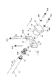
- FIG. 3 is an exploded view showing an example of the end 72 of the ball screw 7 and its periphery.
- FIG. 4 shows an example of the end 72 of the ball screw 7 and its periphery in a cross-sectional view at the position A1 in FIG.
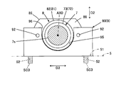
- FIG. 5 shows a state in which the end portion 72 of the ball screw 7 and its periphery are viewed from the opening 96 side of the recess 95 in the support portion 9.
- the base 5 corresponds to any of the bed 2, the Z1 axial slide base 32, and the Z2 axial slide base 42 shown in FIG.
- the movable body 6 includes an X1 axial slide base 31 on which the headstock 10 is installed, a Z1 axial slide base 32 on which the X1 axial slide base 31 is installed, an X2 axial slide base 41 on which the tool post 20 is installed, and X2.
- This corresponds to one of the Z2 axial slide bases 42 on which the axial slide bases 41 are installed.
- the ball screw 7 corresponds to any of the ball screws 31b, 32b, 41b, and 42b shown in FIG.
- the nut 7n of the ball screw 7 corresponds to any of the nuts 31n, 32n, 41n, 42n
- the screw shaft 7s of the ball screw 7 corresponds to any of the screw shafts 31s, 32s, 41s, 42s.
- the servo motor M0 installed on the base 5 corresponds to any of the motors M11, M12, M21, and M22 shown in FIG.
- the base 5 has an attachment portion 51 for attaching a support member 90 as an example of the support portion 9 with a plurality of screws SC3.
- the attachment portion 51 has screw holes 52 that are screwed into the screws SC3.
- the moving body 6 is arranged so as to be movable in a predetermined axial direction D1 with respect to the base 5 as shown in FIGS. 2A to 2D.
- the axial direction D1 is a direction along the center line AX0 of the screw shaft 7s of the ball screw 7.
- the moving body 6 has a main body 61 and a bracket 62 provided with a through hole 63 for mounting the nut 7n of the ball screw 7.
- the bracket 62 protrudes downward from the main body 61, that is, toward the screw shaft 7s.
- the through hole 63 penetrates the bracket 62 in the axial direction D1.
- the ball screw 7 has a nut 7n and a screw shaft 7s that are screwed together via a ball (not shown).
- the screw shaft 7s rotates around the center line AX0 directed in the axial direction D1, thereby moving the nut 7n fixed to the moving body 6 in the axial direction D1.
- One end 71 of the screw shaft 7s is connected to the motor M0 via a coupling C0 which is a torque transmission mechanism in the motor support member MS.
- a rolling bearing 73 is fitted on the other end 72 of the screw shaft 7 s and is fixed by a lock nut 74.
- the end 72 is inserted into the recess 83 of the main body 81 of the cap member 8 and is positioned by the support member 90 and the cap member 8.
- the bearing 73 a ball bearing, a roller bearing, or the like can be used.
- the coupling C0 connects the shaft member Ma of the motor M0 and the end 71 of the screw shaft 7s, and rotates about the center line AX0 as the shaft member Ma rotates to rotate the screw shaft 7s.
- a spun ring having a hub coupled to the shaft (the shaft member Ma or the end portion 71) by tightening a screw can be used as the coupling C0.
- the spun ring is a wedge-shaped frictional engagement element.
- the motor M0 is supported by a motor support member MS mounted on the base 5 and rotationally drives the screw shaft 7s via the coupling C0 in accordance with a command from the NC device 3.
- the ball screw 7 moves the moving body 6 together with the nut 7n in the axial direction D1.
- the cap member 8 enters the concave portion 95 of the support member 90, and the cap member 8 does not enter the concave portion 95 of the support member 90 and protrudes outside D1o in the axial direction D1 from the main body portion 81.
- the flange portion 85 is provided.
- the main body 81 has a concave section 83 having a circular cross section into which an end 72 into which the bearing 73 is fitted on the screw shaft 7s is inserted, and covers the end 72 of the screw shaft 7s. As a result, the main body 81 allows the screw shaft 7s to rotate around the center line AX0.
- the outer surface 82 of the main body 81 is circular when viewed from the side, and is slightly smaller than the curved surface portion of the recess 95 of the support member 90. This is because the main body 81 is placed in the recess 95 and the flange 85 is brought into contact with the positioning portion 91 so that the mounting posture of the ball screw 7 is determined and the direction perpendicular to the axial direction D1 (here shown in FIGS. 3 and 4). This is to finely adjust the position of the ball screw 7 in the direction D2 and in the direction D3 perpendicular to both directions D1 and D2. Therefore, usually, a slight gap is generated between the main body 81 and the recess 95.
- the flange portion 85 extends in the radial direction from the main body portion 81 around the center line AX0, and has screw insertion holes 87 for passing the plurality of screws SC2 in the axial direction D1.
- An inner surface 86 of the flange portion 85 is in contact with the positioning portion 91 of the support member 90.
- the diameter of the screw insertion hole 87 is larger than the diameter of the screw SC2. This is because the position of the ball screw 7 is finely adjusted and the cap member 8 is fixed by the screw SC2 in a state where the mounting posture of the ball screw 7 is determined as described above.
- the concave portion 83 may enter the flange portion 85.
- the support member 90 which is an example of the support portion 9, includes a screw hole 92 to be screwed into each screw SC 2, a screw insertion hole 93 for passing each of the plurality of screws SC 3, and a main body portion 81. And a planar positioning portion 91 against which the inner surface 86 of the flange portion 85 abuts.
- FIG. 3 shows that each screw SC ⁇ b> 2 is screwed into the screw hole 92 through the washer WA ⁇ b> 1 and the screw insertion hole 87.
- Each screw insertion hole 93 penetrates in a direction D2 orthogonal to the axial direction D1. The diameter of the screw insertion hole 93 is larger than the diameter of the screw SC3.
- the support member 90 is fixed by the screw SC3 with the positioning portion 91 against which the inner surface 86 of the flange portion 85 abuts as a vertical surface on which the mounting posture of the ball screw 7 is determined.
- the positioning portion 91 is a vertical surface and each screw SC3 is passed through the screw insertion hole 93 and screwed into the screw hole 52 of the mounting portion 51 of the base 5, the support member 90 is fixed on the mounting portion 51, and this support The member 90 can support the cap member 8.
- the recess 95 is substantially U-shaped, and is an opening 96 through which the main body 81 of the cap member 8 can pass in a direction D2 orthogonal to the axial direction D1 in a state where the support member 90 is fixed to the mounting portion 51.
- the curved surface portion of the recess 95 is slightly larger than the outer surface 82 of the main body portion 81.
- the opening 96 faces in the direction opposite to the base 5. Therefore, the opening 96 allows the screw shaft 7s to pass in the direction D2 orthogonal to the axial direction D1 in a state where the support member 90 is fixed to the mounting portion 51.
- the positioning portion 91 is on the outer surface of the support member 90 in the axial direction D1, and the inner surface 86 of the flange portion 85 abuts in the axial direction D1 in a state where the concave portion 95 receives the main body portion 81.
- one end 71 of the screw shaft 7s can be pulled out from the coupling C0, and the ball screw 7 together with the cap member 8 can be pulled out to the outside D1o in the axial direction D1 to some extent.
- the screw shaft 7s passes through the bracket 62 of the moving body 6 between the nut 7n and the cap member 8, the ball screw 7 cannot be completely drawn out to the outer side D1o in the axial direction D1.
- the ball screw 7 is moved to the motor M0 side unless the screw shaft 7s is tilted. It cannot be pulled out.
- the recess 95 of the support member 90 has an opening 96 that allows the screw shaft 7s to pass in a direction D2 orthogonal to the axial direction D1 in a state where the support member 90 is attached to the base 5.
- one end 71 can be easily moved upward, that is, away from the base 5 so that the screw shaft 7 s is inclined toward the opening 96.
- the cap member 8 By removing the cap member 8 from the other end 72 of the screw shaft 7s, the other end 72 of the screw shaft 7s can be pulled out from the through hole 63 of the bracket 62, and the ball screw 7 can be completely pulled out to the motor M0 side. it can.
- the ball screw 7 can be completely pulled out by easily tilting the screw shaft 7 s toward the opening 96 of the recess 95 without removing the support member 90 from the base 5. it can.
- the work may be performed in the reverse order of the above-described removal procedure.
- one end 71 of the screw shaft 7 s is tilted upward, and the other end 72 of the screw shaft 7 s is passed through the through hole 63 of the bracket 62. Since the recess 95 of the support member 90 has an opening 96 on the side where the screw shaft 7s is inclined in a state where the support member 90 is attached to the base 5, it is necessary to remove the support member 90 from the base 5. No. Next, as shown in FIG.
- the cap member 8 is attached to the end portion 72 of the screw shaft 7s, one end portion 71 of the screw shaft 7s is inserted into the coupling C0, and the main body portion 81 of the cap member 8 is supported by the support member. 90 recesses 95 are inserted.
- the support member 90 remains attached to the base 5, the positioning part 91 of the support member 90 is maintained on the vertical plane. Accordingly, when the inner surface 86 of the flange portion 85 is abutted against the positioning portion 91 of the support member 90 in the axial direction D1, the mounting posture of the ball screw 7 is determined. In this state, when the position of the ball screw 7 in the direction orthogonal to the axial direction D1 (here, directions D2 and D3 shown in FIGS. 3 and 4) is finely adjusted and the cap member 8 is fixed with the screw SC2, the ball screw 7 is attached. Is completed.
- the support member When the support member is attached to the base and does not have an opening that allows the screw shaft to pass therethrough, the screw shaft interferes with the support member, so it is difficult to tilt the ball screw. In this case, in order to replace the ball screw, it is necessary to remove the support member from the base.
- the ball screw mounting posture is such that the parallelism of the screw shaft is confirmed while performing the axis feed movement using a pick tester. It is necessary to fix the support member to the base after performing the adjustment and confirmation work. Therefore, such work needs to be performed by an operator having skill and experience.
- this specific example since it is not necessary to remove the support member from the base when the ball screw is replaced, an operation requiring skill and experience of adjusting or confirming the mounting posture of the ball screw becomes unnecessary. Since the mounting position of the ball screw is determined by applying the flange portion of the cap member to the positioning portion of the support member, the operator may finely adjust the position of the ball screw and fix the cap member to the support member. Therefore, this specific example can reduce the work of replacing the ball screw regardless of the skill and experience of the operator. Further, as shown in FIG. 4, since the concave portion 95 of the support member 90 has the opening 96, the support member 90 does not need to surround the screw shaft 7s, and the height of the support member 90 can be reduced. Therefore, this specific example can make the support portion compact.
- the machine tool may be a main spindle fixed NC lathe or the like.
- the support portion 9 does not need to be removed from the base 5, it may be a portion formed integrally with the base 5.
- the direction of the opening 96 of the recess 95 in the support portion 9 is not limited to the direction opposite to the base 5.
- the support portion is not removed from the base by tilting the screw shaft toward the opening.
- the ball screw can be replaced.
- the direction of the opening of the recess in the support portion may be a direction shifted from the vertical direction or the horizontal direction as long as the screw shaft can pass through the opening.
- the fixing of the cap member 8 to the support portion 9 is not limited to the fixing by the screw SC2, but may be fixing using another case, fixing by a claw member shown in FIG.
- FIG. 6 shows a state in which another example of fixing the cap member 8 to the support portion 9 is viewed from the flange portion 85 side.
- the support member 90 shown in FIG. 6 has a plurality of claw members 110 that can be tilted. When each claw member 110 stands like a solid line portion, it holds the flange portion 85 between it and the positioning portion 91, and when it is tilted like a two-dot chain line portion, the holding of the flange portion 85 is released. Even in this case, the mounting posture of the ball screw 7 is determined by the inner surface 86 of the flange portion 85 being abutted against the positioning portion 91 of the support member 90 in the axial direction D1.
- FIG. 7 shows another example of the end of the ball screw and its periphery in a cross-sectional view at the position A1 in FIG.
- the concave portion 95 of the support member 90 shown in FIG. 7 has a rectangular shape in side view.
- the lower side of the outer surface 82 of the main body 81 of the cap member 8 is shaped to match the rectangular recess 95. Even in this case, the mounting posture of the ball screw 7 is determined by the inner surface 86 of the flange portion 85 being abutted against the positioning portion 91 of the support member 90 in the axial direction D1.
Landscapes
- Engineering & Computer Science (AREA)
- Mechanical Engineering (AREA)
- General Engineering & Computer Science (AREA)
- Transmission Devices (AREA)
- Supporting Of Heads In Record-Carrier Devices (AREA)
- Glass Compositions (AREA)
- Soil Working Implements (AREA)
Abstract
L'invention concerne un outil d'usinage dans lequel l'effort d'échange d'une vis à billes peut être atténué. L'outil d'usinage (1) selon l'invention est doté : d'une base (5) ; d'un corps mobile (6) ; d'une vis à billes (7) présentant un écrou (7n) et un arbre à vis (7s) ; d'un élément de capuchon (8) qui recouvre une extrémité de l'arbre à vis (7s) et permet la rotation de l'arbre à vis (7s) autour de la ligne centrale (AX0) ; et d'une partie de support (9) qui est disposée sur la base (5) de manière à supporter l'élément de capuchon (8). L'élément de capuchon (8) inclut : une section de corps (81) ; et une section de bride (85) qui est disposée au niveau du côté externe (D1o), dans la direction d'axe (D1), à partir de la section de corps (81) et qui est plus large que la section de corps (81). La partie de support (9) inclut : un évidement (95) dans lequel une ouverture (96) permettant de faire passer l'arbre à vis (7s) dans une direction (D2) orthogonale à la direction d'axe (D1) dans l'état où la partie de support (9) est fournie à la base (5) est fournie pour recevoir la section de corps (81) ; et une section de positionnement (91) sur laquelle une surface interne (86) de la section de bride (85) vient en butée dans la direction d'axe (D1) dans l'état dans lequel l'évidement (95) reçoit la section de corps (81).
Priority Applications (3)
| Application Number | Priority Date | Filing Date | Title |
|---|---|---|---|
| EP18915724.1A EP3766632B1 (fr) | 2018-04-16 | 2018-12-27 | Machine-outil |
| CN201880085686.5A CN111712351B (zh) | 2018-04-16 | 2018-12-27 | 机床 |
| US17/032,230 US11358225B2 (en) | 2018-04-16 | 2020-09-25 | Machine tool |
Applications Claiming Priority (2)
| Application Number | Priority Date | Filing Date | Title |
|---|---|---|---|
| JP2018-078372 | 2018-04-16 | ||
| JP2018078372A JP7157306B2 (ja) | 2018-04-16 | 2018-04-16 | 工作機械 |
Related Child Applications (1)
| Application Number | Title | Priority Date | Filing Date |
|---|---|---|---|
| US17/032,230 Continuation US11358225B2 (en) | 2018-04-16 | 2020-09-25 | Machine tool |
Publications (1)
| Publication Number | Publication Date |
|---|---|
| WO2019202779A1 true WO2019202779A1 (fr) | 2019-10-24 |
Family
ID=68240221
Family Applications (1)
| Application Number | Title | Priority Date | Filing Date |
|---|---|---|---|
| PCT/JP2018/048027 Ceased WO2019202779A1 (fr) | 2018-04-16 | 2018-12-27 | Outil d'usinage |
Country Status (6)
| Country | Link |
|---|---|
| US (1) | US11358225B2 (fr) |
| EP (1) | EP3766632B1 (fr) |
| JP (1) | JP7157306B2 (fr) |
| CN (1) | CN111712351B (fr) |
| TW (1) | TWI803620B (fr) |
| WO (1) | WO2019202779A1 (fr) |
Families Citing this family (4)
| Publication number | Priority date | Publication date | Assignee | Title |
|---|---|---|---|---|
| EP3244201B1 (fr) | 2016-05-13 | 2021-10-27 | Honeywell International Inc. | Capteur d'humidité à base de tec avec couche barrière protégeant le diélectrique de grille |
| JP7511237B2 (ja) * | 2019-12-17 | 2024-07-05 | 株式会社アイエイアイ | アクチュエータ |
| JP6994099B1 (ja) | 2020-10-28 | 2022-01-14 | 株式会社スギノマシン | 穴あけ機 |
| WO2023145075A1 (fr) * | 2022-01-31 | 2023-08-03 | ファナック株式会社 | Mécanisme d'arbre d'alimentation |
Citations (6)
| Publication number | Priority date | Publication date | Assignee | Title |
|---|---|---|---|---|
| JPH0253545A (ja) * | 1988-08-12 | 1990-02-22 | Mitsubishi Heavy Ind Ltd | 送りねじ装置 |
| JPH0569352A (ja) * | 1991-09-09 | 1993-03-23 | Smc Corp | アクチユエータおよびその構造体 |
| JPH08118199A (ja) * | 1994-10-24 | 1996-05-14 | Makino Milling Mach Co Ltd | 工作機械の送り装置 |
| JP2005066716A (ja) * | 2003-08-28 | 2005-03-17 | Toyo Seiki Kogyo Co Ltd | ネジ送り機構、このネジ送り機構を備える加工装置およびネジ送り機構の製造方法 |
| JP2006097869A (ja) | 2004-09-30 | 2006-04-13 | Nsk Ltd | 直動テーブル装置 |
| US20130239854A1 (en) * | 2012-03-19 | 2013-09-19 | Fu-Chun Huang | Screw and nut assembly with screw rod support means |
Family Cites Families (18)
| Publication number | Priority date | Publication date | Assignee | Title |
|---|---|---|---|---|
| DE2739087A1 (de) * | 1976-08-30 | 1978-03-09 | Komatsu Mfg Co Ltd | Werkzeugmaschine |
| US4561814A (en) * | 1981-07-09 | 1985-12-31 | Dahlgren Jr William V | Mechanical tool manipulating method and apparatus |
| CH658819A5 (de) * | 1982-07-31 | 1986-12-15 | Hauni Werke Koerber & Co Kg | Antriebsmittel fuer den vorschub eines werkzeugmaschinentisches. |
| KR910005549B1 (ko) * | 1987-10-09 | 1991-07-31 | 올림푸스 옵티칼 캄파니 리미티드 | 현미경의 스테이지 이송용 조미동 공용축 핸들 |
| JP3165115B2 (ja) * | 1991-08-01 | 2001-05-14 | エスエムシー株式会社 | アクチュエータ |
| JPH07106527B2 (ja) * | 1993-07-05 | 1995-11-15 | 功 庄田 | 複合加工機のテーブル移動装置 |
| CN1174303A (zh) * | 1996-08-19 | 1998-02-25 | Smc株式会社 | 电传动装置 |
| JP3927285B2 (ja) * | 1997-07-08 | 2007-06-06 | 日本トムソン株式会社 | スライド装置 |
| JP2001219325A (ja) * | 2000-02-08 | 2001-08-14 | Shinx Ltd | ガントリー型の工作機械 |
| JP4190738B2 (ja) * | 2001-02-07 | 2008-12-03 | 株式会社ジェイテクト | 工作機械における半浮上式スライド案内機構 |
| JP2006118574A (ja) * | 2004-10-20 | 2006-05-11 | Nsk Ltd | ステージ駆動装置 |
| JP4604706B2 (ja) * | 2004-12-21 | 2011-01-05 | 日本精工株式会社 | ステージ駆動装置 |
| US20090067941A1 (en) * | 2007-09-07 | 2009-03-12 | Feng-Tien Chen | CNC machine tool having a sliding member movable at a high speed |
| JP5397236B2 (ja) * | 2010-01-18 | 2014-01-22 | Smc株式会社 | 送りねじ機構 |
| TWI586463B (zh) * | 2015-01-06 | 2017-06-11 | Chen Peng-Ren | CNC double spindle drive |
| CN105058074A (zh) * | 2015-07-23 | 2015-11-18 | 洪子涵 | 螺杆传动支撑装置 |
| CN205904751U (zh) * | 2016-08-10 | 2017-01-25 | 锕玛科技股份有限公司 | 滚珠螺杆滑台 |
| US10293442B2 (en) * | 2017-07-07 | 2019-05-21 | Baizheng Innovation Technology Co., Ltd. | C-type CNC machine center |
-
2018
- 2018-04-16 JP JP2018078372A patent/JP7157306B2/ja active Active
- 2018-12-27 CN CN201880085686.5A patent/CN111712351B/zh active Active
- 2018-12-27 WO PCT/JP2018/048027 patent/WO2019202779A1/fr not_active Ceased
- 2018-12-27 EP EP18915724.1A patent/EP3766632B1/fr active Active
-
2019
- 2019-04-16 TW TW108113195A patent/TWI803620B/zh active
-
2020
- 2020-09-25 US US17/032,230 patent/US11358225B2/en active Active
Patent Citations (6)
| Publication number | Priority date | Publication date | Assignee | Title |
|---|---|---|---|---|
| JPH0253545A (ja) * | 1988-08-12 | 1990-02-22 | Mitsubishi Heavy Ind Ltd | 送りねじ装置 |
| JPH0569352A (ja) * | 1991-09-09 | 1993-03-23 | Smc Corp | アクチユエータおよびその構造体 |
| JPH08118199A (ja) * | 1994-10-24 | 1996-05-14 | Makino Milling Mach Co Ltd | 工作機械の送り装置 |
| JP2005066716A (ja) * | 2003-08-28 | 2005-03-17 | Toyo Seiki Kogyo Co Ltd | ネジ送り機構、このネジ送り機構を備える加工装置およびネジ送り機構の製造方法 |
| JP2006097869A (ja) | 2004-09-30 | 2006-04-13 | Nsk Ltd | 直動テーブル装置 |
| US20130239854A1 (en) * | 2012-03-19 | 2013-09-19 | Fu-Chun Huang | Screw and nut assembly with screw rod support means |
Also Published As
| Publication number | Publication date |
|---|---|
| CN111712351A (zh) | 2020-09-25 |
| JP7157306B2 (ja) | 2022-10-20 |
| TWI803620B (zh) | 2023-06-01 |
| CN111712351B (zh) | 2023-05-05 |
| EP3766632A4 (fr) | 2021-12-15 |
| US20210008631A1 (en) | 2021-01-14 |
| EP3766632A1 (fr) | 2021-01-20 |
| EP3766632B1 (fr) | 2024-04-10 |
| US11358225B2 (en) | 2022-06-14 |
| JP2019181645A (ja) | 2019-10-24 |
| TW201943983A (zh) | 2019-11-16 |
Similar Documents
| Publication | Publication Date | Title |
|---|---|---|
| JP5094465B2 (ja) | 工作機械及び該工作機械を用いたワークの内表面加工方法 | |
| US9162289B2 (en) | Machine tool apparatus and method | |
| WO2019202779A1 (fr) | Outil d'usinage | |
| CN109332725B (zh) | 一种双主轴自动化车床 | |
| JP6917135B2 (ja) | 工作機械 | |
| JPWO2005065869A1 (ja) | 自動旋盤 | |
| JP7234136B2 (ja) | 工具保持装置及び工作機械 | |
| JP4280253B2 (ja) | ワーク回転装置 | |
| JP5059530B2 (ja) | 複合旋盤及び複合旋盤におけるワークの加工方法 | |
| JP2000117506A (ja) | 自動旋盤 | |
| JP2002011616A (ja) | 歯切工具及び歯切加工方法 | |
| JP3979722B2 (ja) | 旋盤用補助ガイド装置及び補助ガイド装置を備えた自動旋盤 | |
| JPH1015703A (ja) | 多機能旋盤 | |
| JP2001322001A (ja) | 複合加工旋盤 | |
| KR20220161178A (ko) | 공작 기계 | |
| US5765455A (en) | Lathe attachment | |
| KR20220124534A (ko) | 내부를 절삭가공하기 위한 가공장치 | |
| JP6654403B2 (ja) | 加工装置 | |
| CN118527683B (zh) | 一种数控走芯式双主轴车铣复合加工中心及加工方法 | |
| JP2007044792A (ja) | 長物加工用工作機械 | |
| JP7324848B2 (ja) | 工作機械 | |
| JP4257511B2 (ja) | Nc加工装置 | |
| JPH0429489B2 (fr) | ||
| CN121946258A (zh) | 六面加工车床及其加工方法 | |
| JP2024067569A (ja) | 工作機械 |
Legal Events
| Date | Code | Title | Description |
|---|---|---|---|
| 121 | Ep: the epo has been informed by wipo that ep was designated in this application |
Ref document number: 18915724 Country of ref document: EP Kind code of ref document: A1 |
|
| NENP | Non-entry into the national phase |
Ref country code: DE |
|
| ENP | Entry into the national phase |
Ref document number: 2018915724 Country of ref document: EP Effective date: 20201014 |