WO2019207694A1 - Machine de travail pour niveleuse à moteur - Google Patents
Machine de travail pour niveleuse à moteur Download PDFInfo
- Publication number
- WO2019207694A1 WO2019207694A1 PCT/JP2018/016852 JP2018016852W WO2019207694A1 WO 2019207694 A1 WO2019207694 A1 WO 2019207694A1 JP 2018016852 W JP2018016852 W JP 2018016852W WO 2019207694 A1 WO2019207694 A1 WO 2019207694A1
- Authority
- WO
- WIPO (PCT)
- Prior art keywords
- gear
- circle
- external gear
- space
- plate
- Prior art date
- Legal status (The legal status is an assumption and is not a legal conclusion. Google has not performed a legal analysis and makes no representation as to the accuracy of the status listed.)
- Ceased
Links
Images


Classifications
-
- F—MECHANICAL ENGINEERING; LIGHTING; HEATING; WEAPONS; BLASTING
- F16—ENGINEERING ELEMENTS AND UNITS; GENERAL MEASURES FOR PRODUCING AND MAINTAINING EFFECTIVE FUNCTIONING OF MACHINES OR INSTALLATIONS; THERMAL INSULATION IN GENERAL
- F16C—SHAFTS; FLEXIBLE SHAFTS; ELEMENTS OR CRANKSHAFT MECHANISMS; ROTARY BODIES OTHER THAN GEARING ELEMENTS; BEARINGS
- F16C33/00—Parts of bearings; Special methods for making bearings or parts thereof
- F16C33/30—Parts of ball or roller bearings
- F16C33/66—Special parts or details in view of lubrication
- F16C33/6603—Special parts or details in view of lubrication with grease as lubricant
- F16C33/6622—Details of supply and/or removal of the grease, e.g. purging grease
-
- E—FIXED CONSTRUCTIONS
- E02—HYDRAULIC ENGINEERING; FOUNDATIONS; SOIL SHIFTING
- E02F—DREDGING; SOIL-SHIFTING
- E02F3/00—Dredgers; Soil-shifting machines
- E02F3/04—Dredgers; Soil-shifting machines mechanically-driven
- E02F3/76—Graders, bulldozers, or the like with scraper plates or ploughshare-like elements; Levelling scarifying devices
- E02F3/7636—Graders with the scraper blade mounted under the tractor chassis
- E02F3/764—Graders with the scraper blade mounted under the tractor chassis with the scraper blade being pivotable about a vertical axis
-
- E—FIXED CONSTRUCTIONS
- E02—HYDRAULIC ENGINEERING; FOUNDATIONS; SOIL SHIFTING
- E02F—DREDGING; SOIL-SHIFTING
- E02F3/00—Dredgers; Soil-shifting machines
- E02F3/04—Dredgers; Soil-shifting machines mechanically-driven
- E02F3/76—Graders, bulldozers, or the like with scraper plates or ploughshare-like elements; Levelling scarifying devices
- E02F3/7636—Graders with the scraper blade mounted under the tractor chassis
- E02F3/7645—Graders with the scraper blade mounted under the tractor chassis with the scraper blade being pivotable about a horizontal axis disposed parallel to the blade
-
- E—FIXED CONSTRUCTIONS
- E02—HYDRAULIC ENGINEERING; FOUNDATIONS; SOIL SHIFTING
- E02F—DREDGING; SOIL-SHIFTING
- E02F3/00—Dredgers; Soil-shifting machines
- E02F3/04—Dredgers; Soil-shifting machines mechanically-driven
- E02F3/76—Graders, bulldozers, or the like with scraper plates or ploughshare-like elements; Levelling scarifying devices
- E02F3/80—Component parts
- E02F3/84—Drives or control devices therefor, e.g. hydraulic drive systems
- E02F3/844—Drives or control devices therefor, e.g. hydraulic drive systems for positioning the blade, e.g. hydraulically
-
- F—MECHANICAL ENGINEERING; LIGHTING; HEATING; WEAPONS; BLASTING
- F16—ENGINEERING ELEMENTS AND UNITS; GENERAL MEASURES FOR PRODUCING AND MAINTAINING EFFECTIVE FUNCTIONING OF MACHINES OR INSTALLATIONS; THERMAL INSULATION IN GENERAL
- F16C—SHAFTS; FLEXIBLE SHAFTS; ELEMENTS OR CRANKSHAFT MECHANISMS; ROTARY BODIES OTHER THAN GEARING ELEMENTS; BEARINGS
- F16C33/00—Parts of bearings; Special methods for making bearings or parts thereof
- F16C33/30—Parts of ball or roller bearings
- F16C33/58—Raceways; Race rings
- F16C33/581—Raceways; Race rings integral with other parts, e.g. with housings or machine elements such as shafts or gear wheels
-
- F—MECHANICAL ENGINEERING; LIGHTING; HEATING; WEAPONS; BLASTING
- F16—ENGINEERING ELEMENTS AND UNITS; GENERAL MEASURES FOR PRODUCING AND MAINTAINING EFFECTIVE FUNCTIONING OF MACHINES OR INSTALLATIONS; THERMAL INSULATION IN GENERAL
- F16C—SHAFTS; FLEXIBLE SHAFTS; ELEMENTS OR CRANKSHAFT MECHANISMS; ROTARY BODIES OTHER THAN GEARING ELEMENTS; BEARINGS
- F16C33/00—Parts of bearings; Special methods for making bearings or parts thereof
- F16C33/30—Parts of ball or roller bearings
- F16C33/66—Special parts or details in view of lubrication
- F16C33/6637—Special parts or details in view of lubrication with liquid lubricant
- F16C33/6659—Details of supply of the liquid to the bearing, e.g. passages or nozzles
-
- F—MECHANICAL ENGINEERING; LIGHTING; HEATING; WEAPONS; BLASTING
- F16—ENGINEERING ELEMENTS AND UNITS; GENERAL MEASURES FOR PRODUCING AND MAINTAINING EFFECTIVE FUNCTIONING OF MACHINES OR INSTALLATIONS; THERMAL INSULATION IN GENERAL
- F16C—SHAFTS; FLEXIBLE SHAFTS; ELEMENTS OR CRANKSHAFT MECHANISMS; ROTARY BODIES OTHER THAN GEARING ELEMENTS; BEARINGS
- F16C2350/00—Machines or articles related to building
- F16C2350/26—Excavators
Definitions
- the present invention relates to a working machine for a motor grader.
- Patent Document 1 discloses a motor grader.
- the motor grader is provided with a working machine.
- the work machine has a circle that supports the blade.
- the circle supports the blade and is rotatably supported by the draw bar. Since the external gear (pinion) provided in a rotating machine such as a motor meshes with the internal gear provided on the inner peripheral surface of the circle, the circle can be rotated by the rotating machine.
- the blade also rotates as the circle rotates.
- This invention is made in view of the said subject, Comprising: It aims at providing the working machine of the motor grader which can aim at maintenance property improvement and durability ensuring. That is, it is possible to provide a working machine for a motor grader in which a lubricant can be easily supplied to a meshing portion of an external gear of a rotating machine and an internal gear of a circle so that the circle can operate smoothly.
- a working machine for a motor grader includes a draw bar having a draw bar plate extending along a horizontal plane, an outer ring that is annular in a plan view and fixed to a lower surface of the draw bar plate, and an annular in a plan view And a bearing having an inner ring disposed on the inner side of the outer ring and rotatably connected to the outer ring in the circumferential direction and provided with an inner gear on an inner circumferential surface, and an outer gear meshing with the inner gear.
- a rotating machine main body provided to rotate the external gear, and provided on the rotary machine main body to cover the external gear from the outer peripheral side, forming a space between the external gear and being fixed to the drawbar plate
- a circle rotating machine having a gear cover, a rotating machine lubrication portion provided in the gear cover for supplying a lubricant to the space, and fixed to the lower end of the inner ring over the circumferential direction.
- Moni, and a, a circle to form an opening below the said space communicates with the space.
- the working machine of the motor grader is equipped with a rotating machine lubrication unit capable of supplying a lubricant to the space between the rotating machine body of the circle rotating machine and the gear cover. Therefore, the operator can supply the lubricant to the meshing portion without directly accessing the meshing portion of the internal gear and the external gear and supplying (applying) the lubricant. Furthermore, the lubricant supplied to the space between the external gear and the gear cover spreads around the entire circumference of the external gear as the external gear rotates, and then passes between the external gear and the gear cover through the opening formed by the circle. It is discharged from the space between.
- the motor grader working machine of the above aspect it is possible to provide a motor grader working machine capable of improving maintenance and ensuring durability. That is, the lubricant can be easily supplied to the meshing portion between the external gear of the rotating machine and the internal gear of the circle, and the circle can be smoothly operated.
- FIG. 4 is a longitudinal sectional view of the working machine of the motor grader according to the embodiment of the present invention, showing the XX section of FIG. 3.
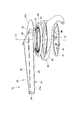
- the motor grader 1 mainly includes traveling wheels 2 and 3, a body frame 4, a cab 8, and a work implement 10.
- the work machine 10 has a blade 90.
- the motor grader 1 performs operations such as leveling work, snow removal work, light cutting, and material mixing with the blade 90.
- the motor grader 1 has front wheels 2 and rear wheels 3 as traveling wheels 2 and 3.
- the motor grader 1 of the present embodiment has two front wheels 2 each having one wheel on one side and four rear wheels 3 each having two wheels on one side.
- the front-rear direction means the front-rear direction of the motor grader 1. That is, the front-rear direction means the front-rear direction viewed from the driver seated on the driver's seat of the cab 8.
- the vehicle width direction means the vehicle width direction of the motor grader 1. That is, the vehicle width direction means the left-right direction as viewed from the driver seated in the driver's seat of the cab 8.
- the vehicle body frame 4 includes a rear frame 5, a front frame 6, and an exterior cover 7.
- the rear frame 5 supports components (not shown) such as an exterior cover 7 and an engine disposed in the engine compartment.
- the exterior cover 7 covers the engine room behind the cab 8.
- Each of the four rear wheels 3 is attached to the rear frame 5 so as to be rotationally driven by a driving force from the engine.
- the front frame 6 is attached in front of the rear frame 5.
- a counterweight 6 a is attached to the front end of the front frame 6.
- the two front wheels 2 are rotatably attached to the lower end of the front frame 6.
- the cab 8 is placed on the front part of the rear frame 5. Inside the cab 8 are provided operating sections (not shown) such as a handle, a speed change lever, an operating lever of the work machine 10, a brake, an accelerator pedal, an inching bead.
- operating sections such as a handle, a speed change lever, an operating lever of the work machine 10, a brake, an accelerator pedal, an inching bead.
- the working machine 10 includes a draw bar 20, a bearing 30 provided with an internal gear 30a, a circle rotating machine 50 provided with an external gear 50a, a circle 60, A rotating machine lubrication unit 40 that supplies the lubricant L to the external gear 50a and a bottom cover 70 are provided.
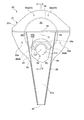
- the draw bar 20 includes a draw bar plate 21, a lateral rib 22, a longitudinal rib 23, a curved rib 26, and a curved rib recess 26a.
- the drawbar plate 21 has a plate shape extending along a horizontal plane.
- the upper surface and the lower surface of the drawbar plate 21 have a planar shape along a horizontal plane.
- the drawbar plate 21 extends with the longitudinal direction as the longitudinal direction.
- a portion on the front side of the drawbar plate 21 is a plate front portion 21a that tapers toward the front side in plan view.
- the rear side portion of the drawbar plate 21 is a plate rear portion 21b having a dimension in the vehicle width direction larger than that of the plate front portion 21a.
- the plate rear portion 21b has a shape in which the width in the vehicle width direction gradually increases from the rear end toward the rear side from the rear end of the plate front portion 21a, and the distance in the vehicle width direction decreases further toward the rear. .
- the lateral rib 22 has a plate shape that protrudes from the upper surface of the plate rear portion 21b of the draw bar plate 21 and extends in the vehicle width direction.
- the lateral rib 22 is provided at a position in the front-rear direction where the vehicle width direction is maximum in the plate rear portion 21b.
- the vertical ribs 23 project from the draw bar plate 21 and have a plate shape extending in the front-rear direction over the plate front portion 21 a and the plate rear portion 21 b of the draw bar plate 21.
- a pair of the vertical ribs 23 is provided at intervals in the vehicle width direction.
- Each vertical rib 23 has a rear end connected to the front surface of the horizontal rib 22.
- the front-rear direction position of the tip of each vertical rib 23 coincides with the tip of the plate front portion 21a.
- the pair of vertical ribs 23 are provided such that the distance between the pair of vertical ribs 23 in the vehicle width direction decreases toward the front side.
- the portions of the pair of vertical ribs 23 on the plate front portion 21a extend in alignment with the side edges of the plate front portion 21a in the vehicle width direction in plan view.
- the front part and the center part defined by the pair of vertical ribs 23 and the horizontal ribs 22 are the front area A1.
- a through hole 21c that penetrates the drawbar plate 21 in the vertical direction is formed in the front region A1.
- the through hole 21c is formed at a position near the center in the vehicle width direction.
- the rear side portion of the lateral rib 22 is a rear area A2.
- a portion between the surface of each vertical rib 23 facing the vehicle width direction outer side and the front surface of the horizontal rib 22 is a side region A3.
- a pair of the side regions A3 are formed at intervals in the vehicle width direction.
- a connecting portion 24 is provided between the front end of the pair of vertical ribs 23 and the front end of the drawbar plate 21.
- a sliding member (not shown) is connected to the connecting portion 24.
- the sliding member is connected to the front frame 6.
- the draw bar 20 is connected to each hydraulic cylinder as will be described later.
- the draw bar 20 can swing with respect to the front frame 6 according to the expansion and contraction of each hydraulic cylinder.
- the curved rib 26 is provided so as to protrude downward from the lower surface of the plate rear portion 21 b in the drawbar plate 21.
- the curved rib 26 has a plate-like shape extending in a circumferential direction (hereinafter simply referred to as a circumferential direction) of an imaginary circle centering on an axis O extending in the vertical direction.
- the axis O is located at the center of the plate rear portion 21b.
- the curved rib 26 has a plate shape in which the radial direction of the virtual circle centered on the axis O (hereinafter simply referred to as the radial direction) is the plate thickness direction.
- a portion of the curved rib 26 on the front side extends so as to be recessed rearward so as to avoid the through hole 21c in plan view.
- the curved rib concave portion 26 a is disposed so as to cover the outer periphery of the side surface portion 52 a of the gear cover 52.
- the end 26aE of the curved rib recess 26a and the curved rib 26 are connected by welding.
- the protruding length of the curved rib 26, that is, the vertical dimension of the curved rib 26 is constant over the circumferential direction.
- the protruding length and plate thickness of the curved rib recess 26a are the same as those of the curved rib 26.
- the curved rib 26 extends so as to pass through the front region A1, the rear region A2, and the side region A3 on the upper surface of the draw bar 20 in a plan view. That is, the curved rib 26 overlaps the horizontal rib 22 and the pair of vertical ribs 23 in plan view, and extends so as to straddle the horizontal rib 22 and the pair of vertical ribs 23.
- the curved rib recess 26a is disposed in the front region A1.
- the draw bar 20 is connected to the front frame 6 by a pair of left and right lift cylinders 101 and a draw bar shift cylinder 102.
- the pair of lift cylinders 101 allows the draw bar 20 to be lifted and swung about an axis along the front-rear direction.
- the drawbar shift cylinder 102 allows the drawbar 20 to move relative to the front frame 6 from side to side.
- the bearing 30 is an annular member having an axis O as a center, and is provided in a space between the draw bar 20 and a circle 60 below the draw bar 20. Yes. As shown in FIG. 5, the bearing 30 includes the outer peripheral side wall 62 provided at the outer peripheral side end portion below the draw bar 20 and the curved rib 26 in the circumferential direction other than where the circle rotating machine 50 is installed. Between the outer peripheral side wall 62 and the curved rib 26. The bearing 30 includes an outer ring 31, an inner ring 32, and rolling elements 33.
- the outer ring 31 is an annular member centered on the axis O in plan view. As shown in FIGS. 5 and 6, the outer ring 31 has a rectangular cross-sectional shape orthogonal to the circumferential direction.
- the upper end surface of the outer ring 31 has a flat shape along a horizontal plane.
- the upper end surface of the outer ring 31 is fixed to the lower surface of the plate rear portion 21b in the draw bar 20 in the circumferential direction.
- the outer ring 31 is fixed and integrated with the draw bar plate 21 by a plurality of bolts (not shown) arranged in the circumferential direction through the draw bar plate 21 in the vertical direction.
- the lower end surface of the outer ring 31 has a flat shape along a horizontal plane.
- the lower end surface of the outer ring 31 is positioned below the upper end surface of the outer peripheral side wall portion 62.
- the inner and outer peripheral surfaces of the outer ring 31 have a cylindrical surface parallel to the axis O.
- the outer ring 31 is formed with a plurality of supply holes 31b that penetrate the inner circumferential surface and the outer circumferential surface of the outer ring 31 in the radial direction at intervals in the circumferential direction.
- the supply hole 31b communicates with the outer ring concave groove 31a.
- the outer peripheral surface of the outer ring 31 is opposed to the inner peripheral surface of the outer peripheral side wall 62 of the circle 60 with a gap inward in the radial direction.
- an outer peripheral space S ⁇ b> 1 is formed between the outer peripheral surface of the outer ring 31 and the inner peripheral surface of the outer peripheral side wall portion 62.
- the inner ring 32 is an annular member centering on the axis O in plan view.
- the inner ring 32 has a diameter slightly smaller than that of the outer ring 31, and is disposed on the radially inner side of the outer ring 31.
- the inner ring 32 has a rectangular cross-sectional shape orthogonal to the circumferential direction.
- the upper end surface of the inner ring 32 is positioned one step below the upper end surface of the outer ring 31.
- an upper space R ⁇ b> 1 is formed between the upper end surface of the inner ring 32 and the lower surface of the drawbar plate 21.
- the lower end surface of the inner ring 32 is located one step below the lower end surface of the outer ring 31.
- the outer peripheral surface of the inner ring 32 has a cylindrical surface shape with the axis O as the center.
- the outer peripheral surface of the inner ring 32 is disposed with a slight clearance with respect to the inner peripheral surface of the outer ring 31.
- an inner ring concave groove 32a is formed that is recessed radially inward from the outer peripheral surface and extends in the circumferential direction.
- the vertical position of the inner ring groove 32a corresponds to the vertical position of the outer ring groove 31a.
- An inner gear 30a having unevenness in the circumferential direction so as to form an annular shape centering on the axis O is provided on the inner circumferential side portion of the inner ring 32 in the circumferential direction and the vertical direction.
- the internal gear 30 a is provided integrally with the inner ring 32 so as to protrude radially inward from the inner peripheral surface of the inner ring 32.
- the internal gear 30a is disposed at a distance from the outer peripheral surface of the curved rib recess 26a of the draw bar 20 in the radial direction.
- a space between the internal gear 30a and the curved rib recess 26a is an inner circumferential space R2 extending in the vertical direction and the circumferential direction. The upper end of the inner peripheral space R2 and the upper space R1 communicate with each other.
- the rolling element 33 is provided between the outer ring 31 and the inner ring 32, and the outer ring 31 and the inner ring 32 can be relatively rotated in the circumferential direction by slidingly contacting the outer ring 31 and the inner ring 32.
- the rolling element 33 of this embodiment is a spherical ball.
- a plurality of rolling elements 33 are accommodated in a circumferential direction in an accommodation space formed by the outer ring groove 31a and the inner ring groove 32a.
- a rod-shaped roller may be used as the rolling element 33.
- a plurality of rollers are arranged in the circumferential direction with the center axis of the rollers facing the vertical direction.
- the bearing 30 is provided with a bearing lubrication portion 34 that supplies the lubricant L between the outer ring 31 and the inner ring 32.
- the bearing lubrication part 34 has a through pipe 35 and a connection part 36.
- the through pipe 35 is a pipe extending in the vertical direction.
- the through pipe 35 passes through the draw bar plate 21 and opens above the draw bar plate 21.
- the lower part of the through pipe 35 is located in the outer peripheral side space S1.
- a lubricant (grease) L is pumped from an opening 35a (see FIG. 3) of a through pipe 35 provided above the draw bar plate 21 to supply the lubricant L to the bearing 30 (greasing). )
- a plurality of connecting portions 36 are provided in the outer circumferential side space S ⁇ b> 1 and are respectively attached to the openings of the respective supply holes 31 b on the outer circumferential surface of the outer ring 31.
- the connecting portion 36 is connected to the lower end of the through pipe 35.
- the connecting portion 36 connects the through pipe 35 and the supply hole 31b so as to communicate with each other. As a result, the lubricant L introduced from the opening of the through pipe 35 is supplied to the supply hole 31 b through the through pipe 35 and the connection part 36.
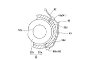
- the circle rotating machine 50 is provided so as to vertically penetrate the through hole 21 c of the drawbar plate 21.
- the circle rotating machine 50 includes a rotating machine main body 51, a gear cover 52, and a flange portion 53.
- the rotating machine main body 51 includes a casing 51a, a worm 51b, a worm wheel 51c, and a shaft 51d.
- the housing 51a houses a worm 51b and a worm wheel 51c.
- the worm 51b is a cylindrical member disposed along the horizontal direction.
- the worm 51b is rotated by a hydraulic device (not shown).
- Screw teeth 51e are formed on the outer peripheral surface of the worm 51b.
- the worm wheel 51c has a cylindrical shape and is disposed above the draw bar plate 21.
- the worm wheel 51c is rotatable around an axis O1 extending in the vertical direction.
- the outer peripheral surface of the worm wheel 51c is formed with a tooth portion 51f that meshes with the screw teeth 51e of the worm 51b.
- the worm wheel 51c is rotated by the rotation of the worm 51b.
- the shaft 51d has a cylindrical shape and is disposed so as to penetrate the draw bar plate 21 in the vertical direction.
- the shaft 51d is inserted into and integrated with the worm wheel 51c.
- the shaft 51d is supported by the housing 51a so as to be rotatable together with the worm wheel 51c about the axis O1.
- An external gear 50a is provided below the shaft 51d.
- the external gear 50 a is a pinion gear and is disposed below the draw bar plate 21.
- a shaft 51d is inserted into and integrated with the external gear 50a.
- the external gear 50a is rotatable with the shaft 51d and the worm wheel 51c about the axis O1.
- a cylindrical upper projecting portion 50a1 having an outer diameter smaller than that of the external gear 50a is provided integrally with the external gear 50a.
- the upper surface of the upper protrusion 50a1 is disposed to face the lower surface of the housing 51a, and an O-ring 55 is provided between the upper surface of the upper protrusion 50a1 and the lower surface of the housing 51a.
- a lower protrusion 50a2 having the same outer diameter as that of the upper protrusion 50a1 is provided integrally with the external gear 50a on the lower surface of the external gear 50a.
- the gear cover 52 is provided integrally with the housing 51a.
- the gear cover 52 has a side surface portion 52a and a lower surface portion 52b provided integrally with the side surface portion 52a.
- the side surface portion 52a covers a portion of the external gear 50a excluding the position where the external gear 50a and the internal gear 30a mesh with each other from the outer peripheral side.
- the side surface portion 52a is disposed away from the external gear 50a in the radial direction of the imaginary circle centered on the axis O1, covers the external gear 50a from the outer peripheral side, and forms a space T1 between the external gear 50a.
- the side surface portion 52 a has a shape in which the external gear 50 a has a part of an annular member centered on the axis O ⁇ b> 1 as viewed from the direction of the axis O ⁇ b> 1.
- the lower surface portion 52b has a disk shape centered on the axis O1, and is provided integrally with the side surface portion 52a at the lower end of the side surface portion 52a.
- the lower surface portion 52b is disposed away from the external gear 50a in the direction of the axis O1, covers the lower side of the external gear 50a, and forms a space T2 with the external gear 50a.
- a part of the lower surface portion 52b is disposed below the inner ring 32 as shown in FIG. That is, a part of the lower surface portion 52b protrudes from the side surface portion 52a toward the inner ring 32 in plan view.
- the lower surface portion 52b is provided with a through hole 52c penetrating in the vertical direction.
- a lid member 54 is inserted into the through hole 52c from below and is fixed to the lower surface portion 52b with a bolt (not shown).
- the upper surface of the lid member 54 is disposed to face the lower surface of the lower protrusion 50a2 provided integrally with the external gear 50a.
- An O-ring 56 is provided between the upper surface of the lid member 54 and the lower surface of the lower protrusion 50a2.
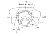
- the flange portion 53 protrudes from the upper end of the gear cover 52 to the outside in the radial direction of the imaginary circle around the axis O ⁇ b> 1, that is, the outside in the radial direction of the external gear 50 a.
- the flange portion 53 is fixed in a state where the circle rotating machine 50 is in contact with the upper surface of the draw bar plate 21 in a state where the circle rotating machine 50 is inserted into the through hole 21 c of the draw bar plate 21.
- a part of the lower surface of the flange portion 53 is exposed downward from the through hole 21c.
- a portion where the flange portion 53 is exposed downward from the through hole 21c is an exposed portion 53a.
- the flange portion 53 can be inserted into and removed from the through hole 21c together with the gear cover 52 and the housing 51a.
- the rotating machine lubrication unit 40 includes a plurality of supply units 41 (41 a and 41 b), a single introduction unit 42, and a connection unit 43.
- the supply part 41 is provided in the inner peripheral space R2 between the side face part 52a and the curved rib concave part 26a.
- the supply portions 41 are provided at a plurality of locations (two locations in the present embodiment) at intervals in the circumferential direction of the external gear 50a, that is, in the circumferential direction of the side surface portion 52a of the gear cover 52.
- Each supply unit 41 is provided at the same vertical position at a position near the upper end of the side surface portion 52a.
- Each supply portion 41 is provided in a supply hole 52d that penetrates the side surface portion 52a of the gear cover 52 in the radial direction of the external gear 50a, and opens toward the space T1.
- Lubricant (grease) L is pumped and supplied (greased) from the supply unit 41 to the space T1.
- connection portion 43 is a tubular member that connects the plurality of supply portions 41a and 41b and through which the lubricant L flows.
- the connecting portion 43 extends in the circumferential direction of the side surface portion 52a of the gear cover 52 along the side surface portion 52a so as to be curved and spaced from the side surface portion 52a.
- the introduction part 42 is connected to only one supply part 41a, extends downward from the supply part 41a, passes through the exposed part 53a of the flange part 53, and above the flange part 53, that is, a draw bar. It is a U-shaped tubular member that opens above the plate 21.
- the lubricant L is introduced into the introduction portion 42 from the opening 42 a (see FIG. 3) on the upper surface of the drawbar plate 21.
- the lubricant L introduced from the opening 42a is supplied to the space T1 through the introduction part 42, the supply part 41, and the connection part 43.
- the circle 60 is provided below the draw bar 20 so as to be rotatable around the axis O via a bearing 30.
- the circle 60 has a circle plate 61, an outer peripheral side wall 62, and a lower side wall 64.
- the circle plate 61 has an annular shape centering on the axis O in plan view and has a plate shape extending in the horizontal direction.
- the upper surface and the lower surface of the circle plate 61 have a planar shape along a horizontal plane.
- the circle plate 61 is fixed to the lower end surface of the inner ring 32 by a fixing member (not shown) such as a bolt over the circumferential direction.
- a fixing member such as a bolt
- the circle plate 61 rotates around the axis O integrally with the inner ring 32.
- the circle plate 61 can rotate relative to the draw bar plate 21 around the axis O via the bearing 30.
- the lower surface of the circle plate 61 is located above the lower end of the curved rib 26 of the draw bar 20.
- the inner peripheral edge 61a of the circle plate 61 is circular with the axis O as the center.
- the inner peripheral edge 61a of the circle plate 61 faces the outer peripheral surface of the curved rib 26 of the draw bar 20 from the radially outer side.
- the radial position of the inner peripheral edge 61 a of the circle plate 61 is a position between the tooth tip of the internal gear 30 a and the outer peripheral surface of the inner ring 32.
- the circle plate 61 is disposed so as to protrude outward in the radial direction from the inner peripheral edge 61a.
- the upper surface of the circle plate 61 and the lower end surface of the outer ring 31 are opposed to each other with an interval in the vertical direction.
- the outer peripheral side wall 62 is provided on the circle plate 61.
- the outer peripheral side wall 62 has a cylindrical shape with the axis O as the center.
- the inner peripheral surface of the outer peripheral side wall 62 is connected to the outer peripheral side of the circle plate 61.
- the outer peripheral side wall 62 extends from the outer periphery of the circle plate 61 toward both the upper side and the lower side.
- the outer peripheral side wall 62 surrounds the bearing 30 from the outer peripheral side.
- the upper end of the outer peripheral side wall 62 faces the lower surface of the draw bar plate 21 with a space in the vertical direction. That is, a clearance C penetrating in the radial direction is formed between the upper end of the outer peripheral side wall 62 and the lower surface of the draw bar plate 21 in the circumferential direction.
- a pair of supports 80 are fixed to the outer peripheral surface of the outer peripheral side wall 62, which is the outer peripheral surface of the circle 60, spaced apart in the vehicle width direction.
- Each support 80 extends rearward along the outer peripheral surface of the circle 60 and then curves and extends downward.
- the circle plate 61 is provided with a lower side wall portion 64.
- the lower wall portion 64 protrudes downward from the lower surface of the circle plate 61 and extends in the circumferential direction.
- the lower side wall portion 64 has an annular shape centered on the axis O in plan view.
- the radial position of the lower side wall portion 64 is a position between the inner peripheral edge portion 61 a of the circle plate 61 and the outer peripheral side wall portion 62.
- the radial position of the lower wall portion 64 is located on the radially outer side with respect to the outer circumferential surface of the inner ring 32 and is located on the radially inner side with respect to the outer circumferential surface of the outer ring 31.
- the inner peripheral edge 61a of the circle plate 61 and the radially outer end of the lower surface 52b of the gear cover 52 are spaced apart from each other in the radial direction, and the inner peripheral edge 61a and the lower surface 52b.
- a gap G1 is formed between the two.
- the bottom cover 70 has a plate shape extending in the horizontal direction while having an outer shape centering on the axis O as a whole in a plan view.
- the bottom cover 70 is divided into a plurality in the circumferential direction.
- Each of the divided bottom covers 70 is structured to be folded at a joint between adjacent bottom covers 70.
- the bottom cover 70 avoids direct application of earth and sand or water to the bearing 30, the gear cover 52, the circle rotating machine 50, and the like on the upper surface side of the bottom cover 70. Further, it is avoided that rocks or the like directly contact the bearing 30, the gear cover 52, the circle rotating machine 50, and the like to damage those devices.
- the upper surface and the lower surface of the bottom cover 70 have a planar shape along a horizontal plane.
- the bottom cover 70 is fixed to the lower ends of the curved rib 26 and the curved rib recess 26a of the draw bar 20 with bolts (not shown) over the circumferential direction.
- the bottom cover 70 may be fixed to the curved rib 26 and the curved rib recess 26a via a bracket or the like. Since the bottom cover 70 is divided into a plurality of parts in the circumferential direction, for example, when performing maintenance on the bearing 30, only the bottom cover 70 corresponding to a predetermined place in the circumferential direction that needs to be inspected can be removed. The maintainability is improved. Further, when a part of the bottom cover 70 is damaged, it is only necessary to replace the bottom cover 70, and the maintenance performance including the maintenance cost can be improved.
- the inner periphery of the bottom cover 70 is disposed along the curved rib 26 and the curved rib recess 26a.
- the bottom cover 70 extends so as to project outward in the radial direction from a fixed portion between the curved rib 26 and the curved rib recess 26a.
- the outer peripheral edge 71 of the bottom cover 70 faces the inner peripheral surface of the lower wall 64 of the circle 60 from the radially inner side.
- an opening G2 is formed between the outer peripheral edge portion 71 of the bottom cover 70 and the inner peripheral surface of the lower side wall portion 64 so as to penetrate vertically in the circumferential direction.
- the opening G2 communicates with the space T1 inside the gear cover 52 through the gap G1, the space T2, and the bottom space R3 described later.
- the lower end of the lower side wall 64 of the circle 60 is located slightly below the lower end of the outer peripheral edge 71 of the bottom cover 70. That is, the lower side wall 64 protrudes downward from the outer peripheral edge 71 of the bottom cover 70.
- the bottom cover 70 is formed with a recessed portion (recessed portion 72) at a position below the circle rotating machine 50 as shown in FIG.
- a lid member 54 provided on the lower surface portion 52 b of the gear cover 52 is disposed in the recess 72.
- the space defined by the outer peripheral surface of the curved rib recess 26a, the lower surface of the circle plate 61, the inner peripheral surface of the lower side wall portion 64, and the upper surface of the bottom cover 70 is a bottom space R3.
- the bottom space R3 communicates with the inner circumferential space R2 through the gap G1. Further, the bottom space R3 communicates with the opening G2.
- the blade 90 extends horizontally below the circle 60.
- the blade 90 is supported by a pair of supports 80. That is, the blade 90 is supported by the circle 60 through the support 80.
- the blade 90 is movable relative to the circle 60 in the extending direction of the blade 90 by a blade shift cylinder (not shown).
- the draw bar 20 can be swung around an axis along the extending direction of the blade 90 by a tilt cylinder 103 shown in FIG.
- the lubricant L can be supplied to the space T1 inside the gear cover 52 through the supplying unit 41 of the rotating machine lubricating unit 40.
- the lubricant L supplied to the space T1 between the external gear 50a and the gear cover 52 spreads all around the external gear 50a as the external gear 50a rotates. Thereafter, the lubricant L flows toward the space T2, and the gap G1 between the inner peripheral edge 61a of the circle plate 61 and the lower surface 52b of the gear cover 52 and the bottom cover 70 as shown in FIGS.
- the lubricant L is discharged through the opening G ⁇ b> 2 between the outer peripheral edge portion 71 and the inner peripheral surface of the lower wall portion 64.
- the lubricant L supplied from the bearing lubrication part 34 to the bearing 30 flows into the upper space R1 above the inner ring through the supply hole 31b of the outer ring 31 and then flows toward the gap G1, and is a space inside the gear cover 52.
- the lubricant L flowing from T 1 toward the gap G 1 is merged and discharged from the opening G 2, and a part of the lubricant L flows down to the recess 72 of the bottom cover 70.
- a plurality of supply portions 41 for supplying the lubricant L are provided on the side surface portion 52a of the gear cover 52 at positions separated in the circumferential direction. Therefore, the lubricant L can be supplied from the supply unit 41 to the space T1 over a wide range in the circumferential direction.
- the introduction part 42 for introducing the lubricant L into the supply part 41 is opened above the draw bar plate 21. Therefore, for example, it is not necessary for the operator to enter under the drawbar plate 21 and introduce the lubricant L into the meshing portion of the internal gear 30a and the external gear 50a. Therefore, according to this embodiment, the operation
- the lubricant L can be supplied from all the supply parts 41 to the space T1. Thereby, the lubricant L can be supplied to the space T1 very easily.
- the gear cover 52 has a lower surface portion 52b, and a lid member 54 is provided on the lower surface portion 52b. Therefore, even when earth and sand or water flows into the bottom space R3 through the opening G2, it is possible to avoid the earth and sand from flowing into the space T1 inside the gear cover 52. Thereby, generation
- the circle rotating machine 50 has a flange portion 53. And a part of lower surface of the flange part 53 is exposed below from the through-hole 21c of the draw bar plate 21, and the flange part 53 has the exposed part 53a. Further, an introduction portion 42 is provided in the exposed portion 53a. Therefore, it is not necessary to provide the introduction portion 42 through the draw bar plate 21. For this reason, even if it is a case where the introducing
- the supply unit 41, the introducing unit 42, and the connecting unit 43 of the rotating machine lubrication unit 40 can be installed and removed integrally with the circle rotating machine 50. It becomes possible. For this reason, the maintainability of the rotating machine lubrication part 40 can also be improved.
- the lubricant L supplied to the space T1 by the rotating machine lubrication unit 40 and the lubricant L supplied to the bearing 30 by the bearing lubrication unit 34 are other lubricants such as a lubricant having a viscosity lower than that of grease. May be used.
- the supply of the lubricant L may be performed automatically, or may be performed manually by an operator using, for example, a grease gun.
- only one supply unit 41 of the rotating machine lubrication unit 34 may be provided. That is, it is sufficient that at least one supply unit 41 is provided.
- the introduction part 42 of the rotating machine lubrication part 34 may be provided through the draw bar plate 21 instead of the flange part 53 of the circle rotating machine 50.
- the introduction part 42 is not limited to the case where the introduction part 42 is opened above the draw bar plate 21, and it is sufficient that the introduction part 42 is opened at a position where the lubricant L can be introduced.
- the gear cover 52 includes the side surface portion 52a and the lower surface portion 52b.
- the gear cover 52 may include only the side surface portion 52a.
- the working machine of the motor grader of the present invention maintenance can be improved and durability can be ensured. That is, the lubricant can be easily supplied to the meshing portion between the external gear of the rotating machine and the internal gear of the circle, and the circle can be smoothly operated.
- lid member 55,56 ... O-ring, 60 ... circle, 61 ... circle plate, 61a ... inner peripheral edge portion, 62 ... outer peripheral sidewall portion, 64 ... Lower side wall portion, 80 ... support, 70 ... bottom cover, 71 ... outer peripheral edge portion, 72 ... recess, 90 ... blade, A1 ... front region, A2 ... rear region, A3 ... side region, O ... axis, O1 ... Axis 101, lift cylinder 102, drawbar shift cylinder S 1 outer space R 1 upper space R 2 inner space R 3 bottom space T 1 space T 2 space C clearer Scan, G1 ... gap, G2 ... opening
Landscapes
- Engineering & Computer Science (AREA)
- General Engineering & Computer Science (AREA)
- Mechanical Engineering (AREA)
- Mining & Mineral Resources (AREA)
- Civil Engineering (AREA)
- Structural Engineering (AREA)
- General Details Of Gearings (AREA)
Abstract
La présente invention concerne une machine de travail (10) pour une niveleuse à moteur (1) qui est pourvue d'une section de lubrification de machine rotative (40) prévue sur un couvercle d'engrenage (52) pour une machine rotative circulaire (50). La machine rotative circulaire (50) comprend : un corps de machine rotatif (51) qui met en rotation un engrenage externe (50) qui s'engrène avec un engrenage interne (30a) prévu sur la surface périphérique intérieure de la bague intérieure (32) d'un palier (30) ; et le couvercle d'engrenage (52) qui est prévu sur le corps de machine rotatif (51), recouvre l'engrenage externe (50a) depuis le côté périphérique extérieur, forme un espace (T1) entre le couvercle d'engrenage (52) et l'engrenage externe (51a), et est fixé à une plaque de barre de traction (21). La section de lubrification de machine rotative (40) fournit un lubrifiant (L) dans l'espace (T1).
Priority Applications (4)
| Application Number | Priority Date | Filing Date | Title |
|---|---|---|---|
| CN201880013958.0A CN110637128B (zh) | 2018-04-25 | 2018-04-25 | 机动平路机的作业装置 |
| PCT/JP2018/016852 WO2019207694A1 (fr) | 2018-04-25 | 2018-04-25 | Machine de travail pour niveleuse à moteur |
| JP2019513460A JP7138097B2 (ja) | 2018-04-25 | 2018-04-25 | モータグレーダの作業機 |
| US16/480,859 US11371208B2 (en) | 2018-04-25 | 2018-04-25 | Work equipment for motor grader |
Applications Claiming Priority (1)
| Application Number | Priority Date | Filing Date | Title |
|---|---|---|---|
| PCT/JP2018/016852 WO2019207694A1 (fr) | 2018-04-25 | 2018-04-25 | Machine de travail pour niveleuse à moteur |
Publications (1)
| Publication Number | Publication Date |
|---|---|
| WO2019207694A1 true WO2019207694A1 (fr) | 2019-10-31 |
Family
ID=68294987
Family Applications (1)
| Application Number | Title | Priority Date | Filing Date |
|---|---|---|---|
| PCT/JP2018/016852 Ceased WO2019207694A1 (fr) | 2018-04-25 | 2018-04-25 | Machine de travail pour niveleuse à moteur |
Country Status (4)
| Country | Link |
|---|---|
| US (1) | US11371208B2 (fr) |
| JP (1) | JP7138097B2 (fr) |
| CN (1) | CN110637128B (fr) |
| WO (1) | WO2019207694A1 (fr) |
Families Citing this family (2)
| Publication number | Priority date | Publication date | Assignee | Title |
|---|---|---|---|---|
| WO2019207692A1 (fr) * | 2018-04-25 | 2019-10-31 | 株式会社小松製作所 | Engin de chantier destiné à une niveleuse automotrice |
| US11505912B2 (en) * | 2019-10-03 | 2022-11-22 | Caterpillar Inc. | Motor grader circle drawbar debris remover |
Citations (3)
| Publication number | Priority date | Publication date | Assignee | Title |
|---|---|---|---|---|
| JP2012163215A (ja) * | 2006-03-24 | 2012-08-30 | Railway Technical Research Institute | 軸受の潤滑構造 |
| US20150135866A1 (en) * | 2013-11-20 | 2015-05-21 | Deere & Company | Sealed guard for motor grader draft apparatus |
| JP2016125587A (ja) * | 2014-12-29 | 2016-07-11 | 株式会社日立製作所 | 風力発電設備および増速機 |
Family Cites Families (11)
| Publication number | Priority date | Publication date | Assignee | Title |
|---|---|---|---|---|
| US4015669A (en) * | 1976-03-03 | 1977-04-05 | Caterpillar Tractor Co. | Circle mounting bar and circle assembly for a motor grader |
| US4122903A (en) * | 1976-06-14 | 1978-10-31 | Caterpillar Tractor Co. | Motor grader circle drive |
| US4185700A (en) * | 1976-06-14 | 1980-01-29 | Caterpillar Tractor Co. | Circle mounting and circle assembly for a motor grader |
| CA2348202C (fr) | 2001-05-18 | 2009-04-28 | Volvo Motor Graders Limited | Reglage de coulisse pour lame niveleuse |
| DE112004001951T5 (de) | 2003-10-21 | 2006-09-07 | Komatsu Ltd. | Achsinnenschmiervorrichtung |
| WO2014203309A1 (fr) * | 2013-06-17 | 2014-12-24 | 株式会社小松製作所 | Niveleuse motorisée |
| JP6289976B2 (ja) | 2014-03-31 | 2018-03-07 | 住友重機械工業株式会社 | 旋回駆動装置 |
| CN107574850A (zh) | 2017-08-24 | 2018-01-12 | 山东临工工程机械有限公司 | 滚盘式工作装置及其滑动回转支撑 |
| US11585411B2 (en) * | 2019-11-11 | 2023-02-21 | Deere & Company | Torque dividing arrangement for a circle drive |
| US11718974B2 (en) * | 2019-12-17 | 2023-08-08 | Deere & Company | Motor graders incorporating mount kits for work implement assemblies and methods of servicing motor graders |
| US11846296B2 (en) * | 2020-03-13 | 2023-12-19 | Carrier Corporation | Flushing of a touchdown bearing |
-
2018
- 2018-04-25 US US16/480,859 patent/US11371208B2/en active Active
- 2018-04-25 WO PCT/JP2018/016852 patent/WO2019207694A1/fr not_active Ceased
- 2018-04-25 JP JP2019513460A patent/JP7138097B2/ja active Active
- 2018-04-25 CN CN201880013958.0A patent/CN110637128B/zh active Active
Patent Citations (3)
| Publication number | Priority date | Publication date | Assignee | Title |
|---|---|---|---|---|
| JP2012163215A (ja) * | 2006-03-24 | 2012-08-30 | Railway Technical Research Institute | 軸受の潤滑構造 |
| US20150135866A1 (en) * | 2013-11-20 | 2015-05-21 | Deere & Company | Sealed guard for motor grader draft apparatus |
| JP2016125587A (ja) * | 2014-12-29 | 2016-07-11 | 株式会社日立製作所 | 風力発電設備および増速機 |
Also Published As
| Publication number | Publication date |
|---|---|
| CN110637128B (zh) | 2021-05-18 |
| US20210355652A1 (en) | 2021-11-18 |
| JPWO2019207694A1 (ja) | 2021-03-18 |
| US11371208B2 (en) | 2022-06-28 |
| CN110637128A (zh) | 2019-12-31 |
| JP7138097B2 (ja) | 2022-09-15 |
Similar Documents
| Publication | Publication Date | Title |
|---|---|---|
| JP7059260B2 (ja) | モータグレーダの作業機 | |
| CN107614800A (zh) | 作业机械 | |
| JP7138097B2 (ja) | モータグレーダの作業機 | |
| US8714660B2 (en) | Chamber for milling machine | |
| US20250074520A1 (en) | Travel driving apparatus | |
| JP7138099B2 (ja) | モータグレーダの作業機 | |
| JP2017133560A (ja) | スイベルジョイント | |
| JP2013203232A (ja) | 作業車用の車軸ケース | |
| US20150192207A1 (en) | Shaft seal assembly for final drive system | |
| JP7138098B2 (ja) | モータグレーダの作業機 | |
| JP7374036B2 (ja) | 建設機械 | |
| JP7818419B2 (ja) | ローラ支持構造体 | |
| JP4740088B2 (ja) | 建設機械 | |
| JP4896799B2 (ja) | 減速装置 | |
| EP3730703B1 (fr) | Engin de chantier | |
| JPH057321Y2 (fr) | ||
| JP2025112477A (ja) | 作業機械の履帯式走行装置 | |
| US20140143993A1 (en) | Method and retrofit kit for oscillation joint | |
| JPH08199626A (ja) | 作業車両の旋回フレーム構造 | |
| JPH11107315A (ja) | 旋回式建設機械 | |
| JP2007078083A (ja) | 軸受装置 |
Legal Events
| Date | Code | Title | Description |
|---|---|---|---|
| ENP | Entry into the national phase |
Ref document number: 2019513460 Country of ref document: JP Kind code of ref document: A |
|
| 121 | Ep: the epo has been informed by wipo that ep was designated in this application |
Ref document number: 18916296 Country of ref document: EP Kind code of ref document: A1 |
|
| NENP | Non-entry into the national phase |
Ref country code: DE |
|
| 122 | Ep: pct application non-entry in european phase |
Ref document number: 18916296 Country of ref document: EP Kind code of ref document: A1 |