WO2019207886A1 - Dispositif de traitement d'informations, procédé de traitement d'informations et programme - Google Patents
Dispositif de traitement d'informations, procédé de traitement d'informations et programme Download PDFInfo
- Publication number
- WO2019207886A1 WO2019207886A1 PCT/JP2019/003391 JP2019003391W WO2019207886A1 WO 2019207886 A1 WO2019207886 A1 WO 2019207886A1 JP 2019003391 W JP2019003391 W JP 2019003391W WO 2019207886 A1 WO2019207886 A1 WO 2019207886A1
- Authority
- WO
- WIPO (PCT)
- Prior art keywords
- polarization
- information
- degree
- object surface
- noise
- Prior art date
- Legal status (The legal status is an assumption and is not a legal conclusion. Google has not performed a legal analysis and makes no representation as to the accuracy of the status listed.)
- Ceased
Links
Images


Classifications
-
- G—PHYSICS
- G06—COMPUTING OR CALCULATING; COUNTING
- G06T—IMAGE DATA PROCESSING OR GENERATION, IN GENERAL
- G06T5/00—Image enhancement or restoration
- G06T5/70—Denoising; Smoothing
-
- G—PHYSICS
- G01—MEASURING; TESTING
- G01B—MEASURING LENGTH, THICKNESS OR SIMILAR LINEAR DIMENSIONS; MEASURING ANGLES; MEASURING AREAS; MEASURING IRREGULARITIES OF SURFACES OR CONTOURS
- G01B11/00—Measuring arrangements characterised by the use of optical techniques
- G01B11/24—Measuring arrangements characterised by the use of optical techniques for measuring contours or curvatures
-
- G—PHYSICS
- G06—COMPUTING OR CALCULATING; COUNTING
- G06T—IMAGE DATA PROCESSING OR GENERATION, IN GENERAL
- G06T7/00—Image analysis
- G06T7/40—Analysis of texture
Definitions
- This technology makes it possible to acquire object surface information that is robust against noise with respect to an information processing apparatus, an information processing method, and a program.
- a polarization image is used to detect the surface shape of a subject.
- the degree of polarization is calculated from a polarization image, and based on the degree of polarization, a shadow region caused by the subject's normal line not facing the light source and the light that is blocked by the shield are generated. Discrimination from the area is performed.
- the object surface information such as the degree of polarization acquired from the polarization image is affected by the noise, and there is a possibility that the accuracy of processing using the object surface information is reduced.
- the information processing apparatus includes an information correction unit that corrects object surface information calculated based on polarization information according to a noise amount of the polarization information.
- the noise amount calculation unit calculates the noise amount of the polarization information for each pixel based on the noise variance generated in the polarization imaging unit that acquired the polarization information.
- the information correction unit calculates the object surface information, for example, the degree of polarization of the object surface, the zenith angle, or the reflection component for each pixel based on the polarization information, and the calculated object surface information is calculated by the noise amount calculation unit. Correct according to the amount of noise.
- the correction of the object surface information is performed based on change characteristic information indicating a change in the object surface information according to the amount of noise.
- the object surface information is a degree of polarization or a specular reflection component
- the information correction unit has, as characteristic information, a table showing the object surface information after change according to the amount of noise for each amount of noise for each degree of polarization.
- the noise amount calculated by the noise amount calculation unit the object surface information before change corresponding to the object surface information after change that minimizes the difference from the object surface information calculated based on the polarization information is corrected. It is object surface information.
- the object surface information is the zenith angle
- the information correction unit has a table indicating the change in the degree of polarization according to the amount of noise for each zenith angle as change characteristic information, and is calculated by the noise amount calculation unit.
- the zenith angle corresponding to the degree of polarization that minimizes the difference from the degree of polarization calculated based on the polarization information in the amount of noise is defined as the corrected zenith angle.
- the information correction unit corrects the object surface information corrected using the correction gain set based on the object surface information calculated based on the noise amount calculated by the noise amount calculation unit and the polarization information.
- the object surface information may be used.
- the noise amount calculation unit calculates the ratio of the average luminance value of the polarization information with respect to the dispersion of the noise of the polarization information as the noise amount.
- the object surface information is a degree of polarization or a specular reflection component
- the information correction unit corrects a DC component obtained by smoothing the object surface information calculated based on the polarization information according to the amount of noise.
- the information correction unit uses the difference between the object surface information calculated based on the polarization information and the direct current component as an alternating current component of the object surface information, and adds the alternating current component and the direct current component corrected according to the amount of noise. The result may be corrected object surface information.
- the object surface information is the zenith angle
- the information correction unit calculates the zenith angle with respect to the degree of polarization that minimizes the difference from the direct current component obtained by smoothing the degree of polarization calculated based on the polarization information.
- a corrected zenith angle a zenith angle corresponding to an alternating current component of the degree of polarization calculated based on polarization information may be added to the zenith angle to obtain a corrected zenith angle.
- the information processing apparatus calculates a non-polarized component from the polarization imaging unit that acquires polarization information, the normal information generation unit that generates normal information based on the object surface information corrected by the information correction unit, or the polarization information.
- a diffuse reflection calculation unit that calculates a diffuse reflection component by subtracting the specular reflection component corrected by the information correction unit from the non-polarized component may be further provided.
- An information processing method includes correcting object surface information calculated based on polarization information by an information correction unit according to a noise amount of the polarization information.
- the third aspect of this technology is A program that causes a computer to calculate object surface information based on polarization information, A program for causing a computer to execute a procedure for correcting object surface information calculated based on the polarization information according to a noise amount of the polarization information.
- the program of the present technology is, for example, a storage medium or a communication medium provided in a computer-readable format to a general-purpose computer that can execute various program codes, such as an optical disk, a magnetic disk, or a semiconductor memory. It is a program that can be provided by a medium or a communication medium such as a network. By providing such a program in a computer-readable format, processing corresponding to the program is realized on the computer.
- the amount of noise in the polarization information is calculated, and the object surface information calculated based on the polarization information is corrected according to the calculated amount of noise. Therefore, object surface information that is robust against noise can be acquired. Note that the effects described in the present specification are merely examples and are not limited, and may have additional effects.
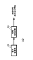
- FIG. 1 exemplifies a system configuration using an information processing apparatus of the present technology.
- the information acquisition system 10 includes a polarization imaging unit 20 and an information processing unit 30.
- the polarization imaging unit 20 acquires different polarization images having polarization directions of at least three directions (which may include non-polarization in the polarization direction) and outputs the acquired polarization images to the information processing unit 30.
- FIG. 2 illustrates the configuration of a polarization imaging unit that acquires a polarization image.
- the polarization imaging unit 20 arranges a polarization filter 202 having a plurality of polarization direction pixel configurations on an image sensor 201 provided with a mosaic filter (not shown) on the imaging surface. It has been configured.
- By performing imaging using the polarization imaging unit 20 having such a configuration it is possible to acquire a polarization image having polarization components in a plurality of directions.
- FIG. 2A illustrates the case where a polarizing filter 202 serving as a pixel in any of four different polarization directions (polarization directions are indicated by arrows) is arranged on the front surface of the image sensor 201.
- FIG. 2B the polarization imaging unit 20 may generate a polarization image having polarization components in a plurality of directions by using the configuration of the multi-lens array.
- a plurality (four in the figure) of lenses 203 are provided on the front surface of the image sensor 201, and an optical image of a subject is formed on the imaging surface of the image sensor 201 by each lens 203.
- a polarizing plate 204 is provided on the front surface of each lens 203 so that the polarizing direction of the polarizing plate 204 is different. If the polarization imaging unit 20 is configured in this way, a polarization image having polarization components in a plurality of directions can be acquired by one imaging. Further, as shown in FIG. 2C, a configuration in which polarizing plates 212-1 to 212-4 having different polarization directions are provided in front of the imaging units 210-1 to 210-4, from a plurality of different viewpoints. A plurality of polarization images having different polarization directions may be generated.
- the parallax can be ignored in a plurality of polarized images having different polarization directions. .
- the polarization images having different polarization directions are aligned according to the parallax amount.
- the information processing unit 30 corrects the object surface information calculated based on the polarization information acquired by the polarization imaging unit 20 according to the noise amount of the polarization information.
- the information processing unit 30 calculates the polarization degree, the zenith angle, or the reflection component of the object surface as the object surface information from the polarization information, for example, the polarization image.
- the information processing unit 30 corrects the calculated object surface information according to the amount of noise in the polarization image based on change characteristic information indicating a change in the object surface information according to the amount of noise.
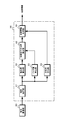
- FIG. 3 illustrates the configuration of the first embodiment.
- the information processing unit 30 includes an interpolation processing unit 31, a polarization degree calculation unit 32, a noise amount calculation unit 33, and a polarization degree correction unit 34.
- a zenith angle calculation unit 41 When the normal information is generated by the information processing unit 30, a zenith angle calculation unit 41, an azimuth angle calculation unit 43, and a normal information generation unit 44 may be further provided.
- the interpolation processing unit 31 may be provided in the polarization imaging unit 20.
- the polarization degree correction unit 34 corresponds to the information correction unit.
- the interpolation processing unit 31 performs an interpolation process using an image signal of a polarization image made up of pixels for each of a plurality of polarization components generated by the polarization imaging unit 20, and generates a polarization image for each polarization component.
- the pixel signal of the interpolation target pixel is calculated based on the pixel signal of the pixel of the same polarization component located in the vicinity of the interpolation target pixel.
- the interpolation processing unit 31 outputs the generated polarization image for each polarization component to the polarization degree calculation unit 32, the noise amount calculation unit 33, and the azimuth angle calculation unit 43.
- the polarization degree calculation unit 32 calculates the polarization degree based on the polarization image for each polarization component.
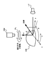
- the relationship between the polarization image and the polarization degree will be described.
- the light source LT is used to illuminate the subject OB
- the imaging unit CM images the subject OB via the polarizing plate PL.
- the luminance of the subject OB changes according to the polarization direction of the polarizing plate PL.
- the highest luminance is Imax and the lowest luminance is Imin.
- the x-axis and y-axis in the two-dimensional coordinates are on the plane of the polarizing plate PL, and the angle in the y-axis direction with respect to the x-axis is a polarization angle ⁇ indicating the polarization direction (transmission axis angle) of the polarizing plate PL.
- the polarizing plate PL returns to the original polarization state when the polarization direction is rotated by 180 degrees, and has a period of 180 degrees.
- the polarization angle ⁇ when the maximum luminance Imax is observed is defined as an azimuth angle ⁇ .
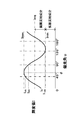
- Equation (1) when the polarization direction of the polarizing plate PL is changed, the observed luminance I ( ⁇ ) can be expressed by the polarization model equation of Equation (1).
- FIG. 5 illustrates the relationship between the luminance and the polarization angle.
- Parameters a, b, and c in Expression (1) are parameters that express a Cos waveform due to polarized light.
- Expression (1) is expressed as Expression (2)
- the luminance I ( ⁇ ) becomes a matrix shown in Expression (3)
- the coefficient A becomes a matrix shown in Expression (4). Therefore, the parameters a, b, and c are values calculated based on Expression (5).
- the parameters a, b, and c can be calculated using the luminance values in the three polarization directions.
- the degree of polarization calculation unit 32 calculates the degree of polarization ⁇ for each pixel based on Expression (6), and outputs it to the degree of polarization correction unit 34. Note that parameters a, b, and c in equation (6) are values calculated based on equation (5).
- the noise amount calculation unit 33 calculates the noise amount based on the polarization image for each polarization component.
- the noise amount calculation unit 33 calculates, as a noise amount, the variance of noise in the average luminance value of the polarization image for each polarization component, based on a preset noise model represented by, for example, Expression (7).
- the average luminance value corresponds to the parameter c in Expression (5).
- the coefficient “n0” is a coefficient used for calculating the variance of the shot noise distribution when the output from the image sensor 201 is an average luminance value.
- the coefficient “n1” corresponds to the distribution of the thermal noise distribution of the image sensor 201.
- the noise amount calculation unit 33 calculates the noise amount SNR for each pixel using the average luminance value (parameter c) and the variance ⁇ based on the equation (8). Note that the unit of the amount of noise shown in Expression (8) is decibels.
- the noise amount calculation unit 33 may perform at least one of time direction and spatial direction filter processing so that the influence of noise can be reduced even if noise is superimposed on the average luminance value. For example, the average luminance value of a plurality of frames at the noise calculation target pixel position may be averaged to obtain the average luminance value of the noise calculation target pixel position. The average luminance value of pixels within a predetermined range with the noise calculation target pixel position as a reference May be averaged to obtain the average luminance value of the noise calculation target pixel position. As described above, the noise amount can be stably calculated by reducing the influence of noise on the average luminance value. The noise amount calculation unit 33 outputs the calculated noise amount to the polarization degree correction unit 34.
- the polarization degree correction unit 34 corrects the polarization degree based on the polarization degree calculated by the polarization degree calculation unit 32 and the noise amount calculated by the noise amount calculation unit 33.
- the polarization degree correction unit 34 has, as change characteristic information, a look-up table LUT [SNR] [ ⁇ ] indicating the degree of polarization after change corresponding to the noise amount for each noise amount.
- the polarization degree correction unit 34 uses the degree of polarization (pin) calculated by the polarization degree calculation unit 32, the noise amount SNR calculated by the noise amount calculation unit 33, and the lookup table LUT [SNR] [ ⁇ ].
- the corrected degree of polarization ⁇ out is output.
- Formula (9) shows a generation formula of the lookup table LUT [SNR] [ ⁇ ].
- the variable ⁇ in the equation (9) is a value calculated based on the equation (10), and I0 () and I1 () in the equation (9) and the equation (37) described later are shown in the equation (11).
- it is the first type modified Bessel function.
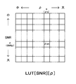
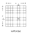
- FIG. 6 illustrates the lookup table LUT [SNR] [ ⁇ ].
- the row direction indicates the polarization degree ⁇ before the change
- the column direction indicates the noise amount SNR.
- the polarization degree It shows the degree of polarization after change, which shows how it changes when ⁇ is the noise amount SNR.
- the polarization degree correction unit 34 calculates the expression (12) by using the polarization degree ⁇ in calculated by the polarization degree calculation unit 32, the noise amount SNR calculated by the noise amount calculation unit 33, and the lookup table.
- the degree of polarization before change corresponding to the degree of polarization after change that minimizes the difference from the calculated degree of polarization ⁇ in in the noise amount SNR is defined as the degree of polarization ⁇ out after correction.
- the noise amount SNR calculated by the noise amount calculation unit 33 is SNRp
- p rows in the lookup table LUT [SNR] [ ⁇ ] are used.
- the difference between the polarization degree ⁇ pq and the polarization degree ⁇ in after the change is minimum in the p-th row
- the polarization degree ⁇ q in the q column of the polarization degree ⁇ pq after the change is set as the corrected polarization degree ⁇ out.
- the polarization degree correction unit 34 outputs the corrected degree of polarization to the zenith angle calculation unit 41. Since the degree of polarization ⁇ is calculated based on the above equation (6), if an error occurs in the parameters a and b due to noise, the error in the direction in which the degree of polarization ⁇ increases regardless of whether the error is positive or negative. Will occur. However, the degree of polarization correction unit 34 can output a degree of polarization with little error to the zenith angle calculation unit 41.
- the zenith angle calculation unit 41 calculates the zenith angle using the corrected polarization degree supplied from the polarization degree correction unit 34.
- the zenith angle calculation unit 41 calculates the zenith angle ⁇ based on the equation (13).
- Expression (13) is a calculation expression when diffuse reflection is dominant, and parameters A, B, C, and D are calculated based on Expressions (14) to (17).
- the parameter n is a relative refractive index.
- the zenith angle calculation unit 41 calculates the zenith angle using equation (18).
- parameters A and B are calculated based on Expressions (19) and (20).
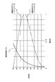
- Fig. 7 shows the relationship between the degree of polarization and the zenith angle.
- the zenith angle since two zenith angles are calculated with respect to the degree of polarization, one of the zenith angles is used. For example, in selecting the zenith angle, information corresponding to the normal line may be calculated from information such as a distance sensor, and the zenith angle may be selected based on the calculation result. For example, the smaller zenith angle is selected so that the selection result is stable. You may always choose.
- the azimuth angle calculation unit 43 calculates the azimuth angle based on the luminance value for each polarization direction.
- the azimuth angle calculation unit 43 calculates the azimuth angle ⁇ based on the formula (21) when diffuse reflection is dominant, and the azimuth angle ⁇ based on the formula (22) when specular reflection is dominant. Is calculated.
- parameters a, b, and c are values calculated based on equation (5).
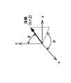
- the normal information generation unit 44 performs calculations of equations (23) to (25) using the zenith angle ⁇ calculated by the zenith angle calculation unit 41 and the azimuth angle ⁇ calculated by the azimuth angle calculation unit 43. As shown in FIG. 8, normal information indicating a normal three-dimensional vector (X, Y, Z) is generated.
- X cos ⁇ ⁇ sin ⁇ (23)
- Y sin ⁇ ⁇ sin ⁇ (24)
- Z cos ⁇ (25)
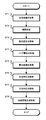
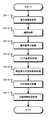
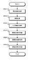
- FIG. 9 is a flowchart illustrating the operation of the first embodiment.
- the information processing unit 30 acquires a polarization image.
- the information processing unit 30 acquires the polarization image generated by the polarization imaging unit 20, and proceeds to step ST2.
- step ST2 the information processing unit 30 performs an interpolation process.
- the interpolation processing unit 31 of the information processing unit 30 performs an interpolation process using the polarization image acquired in step ST1, and generates a polarization image for each polarization component from a polarization image composed of pixels for each of the plurality of polarization components. Proceed to ST3.
- step ST3 the information processing unit 30 performs a polarization degree calculation process.
- the polarization degree calculation unit 32 of the information processing unit 30 performs the calculation of Expression (6) for each pixel using the polarization image for each polarization component, calculates the polarization degree ⁇ , and proceeds to step ST4.
- step ST4 the information processing section 30 performs a noise amount calculation process.
- the noise amount calculation unit 33 of the information processing unit 30 calculates the noise amount SNR for each pixel using the polarization image for each polarization component, and proceeds to step ST5.
- step ST5 the information processing unit 30 performs polarization degree correction processing.
- the polarization degree correction unit 34 of the information processing unit 30 uses a lookup table LUT [SNR] [ ⁇ ] stored in advance, based on the polarization degree calculated in step ST3 and the noise amount calculated in step ST4. Then, the corrected degree of polarization is acquired, and the process proceeds to step ST6.
- step ST6 the information processing section 30 performs a zenith angle calculation process.
- the zenith angle calculation unit 41 of the information processing unit 30 performs the calculation of Expression (13) for each pixel using the corrected polarization degree obtained in step ST5, and proceeds to the calculation step ST7.
- step ST7 the information processing section 30 performs an azimuth calculation process.
- the azimuth angle calculation unit 43 of the information processing unit 30 calculates the azimuth angle ⁇ by performing the calculation of Expression (21) using the polarization image for each polarization component, for example, assuming that diffuse reflection is dominant.
- the azimuth angle ⁇ is calculated based on the equation (22).
- the azimuth calculation unit 43 calculates the azimuth using the polarization image for each polarization component, and proceeds to step ST8.
- step ST8 the information processing section 30 performs normal information generation processing.
- the normal information generation unit 44 of the information processing unit 30 performs calculations of Expressions (23) to (25) using the zenith angle ⁇ calculated in step ST6 and the azimuth angle ⁇ calculated in step ST7, and normals
- the normal information indicating the three-dimensional vector (X, Y, Z) is generated.
- step ST3 or step ST4 may be performed first, and the degree of polarization and the amount of noise may be calculated by parallel processing. Further, the azimuth angle calculation process of step ST7 may be performed at any timing after the interpolation process and before the normal line information generation process. Furthermore, when the polarization image acquired in step ST1 is an image for each polarization direction, it is not necessary to perform the interpolation process in step ST2.
- the degree of polarization in which the influence of noise is corrected based on the change characteristic information indicating the change in degree of polarization according to the amount of noise.
- the degree of polarization ⁇ calculated based on Expression (6) if an error occurs in the parameters a and b due to noise, the error is increased in the direction in which the degree of polarization ⁇ increases, regardless of whether the error is positive or negative. Arise.
- the polarization degree in which the influence of noise is corrected can be calculated, it is possible to generate accurate normal information using the corrected polarization degree.
- Second Embodiment> Next, a second embodiment will be described. In the second embodiment, the configuration is simplified compared to the first embodiment.
- the information processing unit 30 of the second embodiment has the same configuration as that of the first embodiment, and the operation of the polarization degree correction unit is different from that of the first embodiment.
- the polarization degree correction unit 34 uses a correction gain function as change characteristic information indicating a change in the degree of polarization according to the amount of noise.
- the polarization degree correction unit 34 uses a correction gain function to calculate a correction gain according to the noise amount SNR calculated by the noise amount calculation unit 33 and the degree of polarization (pin) calculated based on the polarization image by the polarization degree calculation unit 32. Based on g (SNR, ⁇ in), the degree of polarization ⁇ in is corrected using the calculated correction gain.
- Equation (26) represents a correction equation for the degree of polarization.
- Expression (27) represents the correction gain function g (SNR, ⁇ in), and the variable t is a value calculated based on Expression (28).
- parameter th0 is a value calculated based on Expression (29)
- parameter th1 is a value calculated based on Expression (30).
- the operation of the second embodiment is the same as that of the first embodiment shown in FIG. 9, and the polarization degree correction process in step ST5 is different. That is, the degree of polarization correction unit 34 of the information processing unit 30 acquires the degree of polarization after correction using the degree of polarization calculated in step ST3, the amount of noise calculated in step ST4, and the correction gain function g (SNR, ⁇ in). To do.
- the degree of polarization can be corrected using the correction gain function g (SNR, ⁇ in). Therefore, as in the first embodiment, the lookup table LUT [SNR] [ There is no need to store ⁇ ], and the configuration can be simplified as compared with the first embodiment.
- the information processing unit 30 of the third embodiment has the same configuration as that of the second embodiment, and the operations of the noise calculation unit and the polarization degree correction unit are different from those of the second embodiment.
- the noise amount calculation unit 33 calculates the noise amount based on the polarization image for each polarization component.
- the noise amount calculation unit 33 may perform at least one of the filtering process in the time direction and the spatial direction so that the influence of the noise can be reduced even if the noise is superimposed on the average luminance value. Good.
- the noise amount calculation unit 33 outputs the calculated noise amount to the polarization degree correction unit 34.
- the polarization degree correction unit 34 performs the correction calculation of Expression (26) using the correction gain function g (SNR, ⁇ in) shown in Expression (27), and calculates the corrected degree of polarization ⁇ out. Further, since the noise amount SNR [ratio] calculated by the noise amount calculation unit 33 is the ratio of the average luminance value (parameter c) to the variance ⁇ , the calculation formula for the parameter th1 is the equation (32). Compared with the equation (30) in the embodiment, the parameter th1 can be easily calculated.
- the operation of the third embodiment is the same as that of the first embodiment shown in FIG. 9, and the noise amount calculation process in step ST4 and the polarization degree correction process in step ST5 are different. That is, the noise amount calculation unit 33 of the information processing unit 30 calculates the ratio of the average luminance value to the dispersion as the noise amount SNR [ratio] , and the polarization degree correction unit 34 calculates the degree of polarization calculated in step ST3 and step ST4. The degree of polarization after correction is acquired using the noise amount SNR [ratio] calculated in step (b) and the correction gain function g (SNR, ⁇ in).
- the calculation cost can be reduced as compared with the second embodiment by using the ratio of the average luminance value to the variance as the noise amount calculated by the noise amount calculation unit 33.
- the fourth embodiment has a configuration that is more robust with respect to variations in the degree of polarization compared to the first to third embodiments.
- the information processing unit 30 of the fourth embodiment has the same configuration as that of the second embodiment, and the operation of the polarization degree correction unit is different from that of the second embodiment.
- the polarization degree correction unit 34 corrects the direct current component (DC component) obtained by smoothing the polarization degree ⁇ in calculated by the polarization degree calculation unit 32 according to the noise amount SNR. Further, the polarization degree correction unit 34 calculates the corrected degree of polarization ⁇ out by adding an alternating current component (AC component) of the degree of polarization to the corrected DC component. Equation (33) represents a correction equation for the degree of polarization.
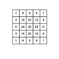
- any method may be used to calculate the DC component ⁇ dc of the degree of polarization ⁇ in, and the polarization degree correction unit 34 smoothes the degree of polarization using, for example, a Gaussian filter to calculate the DC component ⁇ dc.
- FIG. 10 illustrates filter coefficients of the Gaussian filter, and the center position corresponds to the processing target pixel.
- the degree of polarization correction unit 34 calculates the DC component ⁇ dc of the degree of polarization in the processing target pixel by adding the multiplication results of the degree of polarization and the filter coefficient and multiplying the addition result by the sum of the weights.
- the operation of the fourth embodiment is the same as that of the first embodiment shown in FIG. 9, and the polarization degree correction process in step ST5 is different. That is, the polarization degree correction unit 34 of the information processing unit 30 corrects the DC component obtained by smoothing the polarization degree calculated in step ST3 based on the noise amount SNR calculated in step ST4, and the corrected DC component. Is added to the AC component to obtain the corrected polarization degree.
- the fourth embodiment similarly to the first embodiment, it is possible to calculate the degree of polarization in which the influence of noise is corrected and to generate accurate normal information.
- the DC component obtained by smoothing the polarization degree calculated by the polarization degree calculation unit 32 is corrected according to the amount of noise. Robust correction processing is possible.
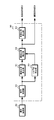
- FIG. 11 illustrates the configuration of the fifth embodiment.
- the information processing unit 30 includes an interpolation processing unit 31, a degree of polarization calculation unit 32, a noise amount calculation unit 33, an error correction zenith angle calculation unit 42, an azimuth angle calculation unit 43, and a normal line information generation unit 44.
- the error correction zenith angle calculation unit 42 corresponds to an information correction unit.
- the interpolation processing unit 31 performs an interpolation process using the image signal of the polarization image composed of pixels for each of the plurality of polarization components generated by the polarization imaging unit 20, and performs the interpolation processing for each polarization component. A polarized image is generated.
- the interpolation processing unit 31 outputs the generated polarization image for each polarization component to the polarization degree calculation unit 32, the noise amount calculation unit 33, and the azimuth angle calculation unit 43.
- the polarization degree calculation unit 32 calculates the degree of polarization for each pixel based on the polarization image for each polarization component, and outputs it to the error correction zenith angle calculation unit 42 as in the first embodiment.
- the noise amount calculation unit 33 calculates the noise amount for each pixel based on the polarization image for each polarization component, and outputs the noise amount to the error correction zenith angle calculation unit 42, as in the first embodiment.
- the error correction zenith angle calculation unit 42 calculates the zenith angle in which the error is corrected based on the polarization degree calculated by the polarization degree calculation unit 32 and the noise amount calculated by the noise amount calculation unit 33.
- the error correction zenith angle calculation unit 42 has a two-dimensional table TN [SNR] [ ⁇ ] indicating change in polarization degree according to the amount of noise for each zenith angle as change characteristic information.
- the error correction zenith angle calculation unit 42 corresponds to the polarization degree ( ⁇ in) calculated by the polarization degree calculation unit 32 and the noise amount SNR calculated by the noise amount calculation unit 33.
- the zenith angle ⁇ out in which the error is corrected is calculated using the two-dimensional table TL [SNR] [ ⁇ ].
- the error correction zenith angle calculation unit 42 acquires the degree of polarization corresponding to the noise amount SNR calculated by the noise amount calculation unit 33 from the two-dimensional table TL [SNR] [ ⁇ ], and is calculated by the polarization degree calculation unit 32.
- the zenith angle corresponding to the degree of polarization that minimizes the difference from the degree of polarization ⁇ in is output to the normal information generation unit 44 as the zenith angle ⁇ out in which the error is corrected.
- Formula (34) shows a formula for calculating the zenith angle ⁇ out in which the error is corrected.
- the azimuth angle calculation unit 43 calculates an azimuth angle based on the luminance value for each polarization direction and outputs the azimuth angle to the normal vector information generation unit 44.
- the normal line information generation unit 44 uses the zenith angle ⁇ calculated by the error correction zenith angle calculation unit 42 and the azimuth angle ⁇ calculated by the azimuth angle calculation unit 43, as in the first embodiment. Normal line information indicating a three-dimensional vector (X, Y, Z) is generated.
- FIG. 12 is a flowchart illustrating the operation of the fifth embodiment.
- the information processing unit 30 acquires the polarization image generated by the polarization imaging unit 20, and proceeds to step ST12.
- step ST12 the information processing unit 30 performs an interpolation process.
- the interpolation processing unit 31 of the information processing unit 30 performs an interpolation process using the polarization image acquired in step ST11, generates a polarization image for each polarization component from a polarization image composed of pixels for each of the plurality of polarization components, and performs step Proceed to ST13.
- step ST13 the information processing section 30 performs a polarization degree calculation process.
- the polarization degree calculation unit 32 of the information processing unit 30 performs the calculation of Expression (6) for each pixel using the polarization image for each polarization component, calculates the polarization degree ⁇ , and proceeds to step ST14.
- step ST14 the information processing section 30 performs a noise amount calculation process.
- the noise amount calculation unit 33 of the information processing unit 30 calculates the noise amount SNR for each pixel using the polarization image for each polarization component, and proceeds to step ST15.
- step ST15 the information processing section 30 performs error correction zenith angle calculation processing.
- the error correction zenith angle calculation unit 42 of the information processing unit 30 uses the two-dimensional table TL [SNR] [ ⁇ ] stored in advance, the degree of polarization calculated in step ST13, and the amount of noise calculated in step ST14.
- the calculation of Expression (34) is performed to calculate the zenith angle in which the error is corrected, and the process proceeds to step ST16.
- step ST16 the information processing section 30 performs azimuth calculation processing.
- the azimuth angle calculation unit 43 of the information processing unit 30 calculates the azimuth angle ⁇ by performing the calculation of Expression (21) using the polarization image for each polarization component, for example, assuming that diffuse reflection is dominant.
- the azimuth angle ⁇ is calculated based on the equation (22).
- the azimuth calculation unit 43 calculates the azimuth using the polarization image for each polarization component, and proceeds to step ST17.
- step ST17 the information processing section 30 performs normal information generation processing.
- the normal information generation unit 44 of the information processing unit 30 performs calculations of Expressions (23) to (25) using the zenith angle ⁇ calculated in step ST15 and the azimuth angle ⁇ calculated in step ST16, and normals
- the normal information indicating the three-dimensional vector (X, Y, Z) is generated.
- any of the processes of step ST13 and step ST14 may be performed first, and the degree of polarization and the amount of noise may be calculated by parallel processing. Further, the azimuth calculation processing in step ST16 may be performed at any timing after the interpolation processing and before the normal information generation processing. Furthermore, when the polarization image acquired in step ST11 is an image for each polarization direction, it is not necessary to perform the interpolation process in step ST12.
- the zenith angle in which the influence of noise is corrected can be calculated.
- normal information can be generated with high accuracy by using the corrected zenith angle.
- the sixth embodiment has a configuration that is more robust with respect to variations in polarization degree than the fifth embodiment.
- the information processing unit 30 of the sixth embodiment has the same configuration as that of the fifth embodiment, and the operation of the error correction zenith angle calculation unit is different from that of the fifth embodiment.
- the error correction zenith angle calculation unit 42 is a two-dimensional DC component (DC component) obtained by smoothing the polarization degree ⁇ in calculated by the polarization degree calculation unit 32, the noise amount SNR calculated by the noise amount calculation unit 33, and two-dimensional. Based on the table TL [SNR] [ ⁇ ], the zenith angle corresponding to the degree of polarization that minimizes the difference from the DC component of the degree of polarization ⁇ in is defined as the zenith angle ⁇ dc in which the error with respect to the DC component is corrected. Note that the process of smoothing the degree of polarization ⁇ in and calculating the DC component may be performed in the same manner as in the fourth embodiment.
- the error correction zenith angle calculation unit 42 adds the zenith angle corresponding to the AC component of the degree of polarization calculated based on the polarization image to the zenith angle in which the error with respect to the DC component is corrected, and the corrected zenith angle ⁇ ] out to the normal information generator 44.
- the error correction zenith angle calculation unit 42 sets the difference between the zenith angle for the polarization degree ⁇ in and the zenith angle for the DC component as the zenith angle of the AC component (AC component). Equation (35) shows a calculation formula for the zenith angle with the error corrected.
- Equation (35) g ⁇ (SNR, ⁇ dc) is a value when the degree of polarization ⁇ in Equation (34) is a DC component ⁇ dc of the degree of polarization.
- g ⁇ ( ⁇ in) is a value when the degree of polarization ⁇ in the equation (13) or equation (18) is the degree of polarization ⁇ in
- g ⁇ ( ⁇ dc) is the degree of polarization ⁇ in the equation (13) or equation (18). Is a DC component ⁇ dc, and (g ⁇ ( ⁇ in) ⁇ g ⁇ ( ⁇ dc)) corresponds to the zenith angle corresponding to the AC component.
- the operation of the sixth embodiment is the same as that of the fifth embodiment shown in FIG. 12, and the error correction zenith angle calculation process in step ST15 is different. That is, the polarization degree correcting unit 34 of the information processing unit 30 obtains the DC component obtained by smoothing the degree of polarization calculated in step ST13, the noise amount SNR calculated in step ST14, and the two-dimensional table TL [SNR] [ ⁇ ]. Based on the above, the corrected zenith angle corresponding to the DC component of the degree of polarization is calculated. The error correction zenith angle calculation unit 42 calculates the zenith angle in which the error is corrected by adding the zenith angle of the AC component to the corrected zenith angle corresponding to the DC component of the polarization degree.
- the zenith angle is corrected according to the DC component obtained by smoothing the polarization degree calculated by the polarization degree calculation unit 32 and the amount of noise. And robust zenith angle can be calculated.
- FIG. 13 illustrates the configuration of the seventh embodiment.
- the information processing unit 30 includes an interpolation processing unit 31, a noise amount calculation unit 33, a specular reflection calculation unit 51, a specular reflection correction unit 52, and a diffuse reflection calculation unit 53.
- the specular reflection correction unit 52 corresponds to the information correction unit.
- the interpolation processing unit 31 performs an interpolation process using the image signal of the polarization image composed of pixels for each of the plurality of polarization components generated by the polarization imaging unit 20, and performs the interpolation processing for each polarization component. A polarized image is generated.
- the interpolation processing unit 31 outputs the generated polarization image for each polarization component to the noise amount calculation unit 33 and the specular reflection calculation unit 51.
- the noise amount calculation unit 33 performs the calculation of Expression (7) using the polarization image for each polarization component, calculates the noise variance ⁇ for each pixel, and uses the specular surface as the noise amount. Output to the reflection correction unit 52.
- the specular reflection calculating unit 51 calculates the specular reflection component s based on the polarization image for each polarization component based on Expression (36).
- the parameters a and b in the equation (36) are calculated based on the equation (5).
- the specular reflection calculation unit 51 outputs the calculated specular reflection component s to the specular reflection correction unit 52.
- the specular reflection correction unit 52 corrects the specular reflection component based on the specular reflection component calculated by the specular reflection calculation unit 51 and the noise amount calculated by the noise amount calculation unit 33.
- the specular reflection correction unit 52 has, as change characteristic information, a look-up table LUT [ ⁇ ] [s] indicating, for each specular reflection component, a specular reflection component after change corresponding to the noise amount for each noise amount.
- the specular reflection correction unit 52 uses the specular reflection component (referred to as sin) calculated by the specular reflection calculation unit 51, the noise amount ⁇ calculated by the noise amount calculation unit 33, and the lookup table LUT [ ⁇ ] [s].
- the corrected specular reflection component sout is output.
- Formula (37) represents a generation formula of the lookup table LUT [ ⁇ ] [s]. Further, the variable ⁇ in Expression (37) is a value calculated based on Expression (38).
- FIG. 14 shows the lookup table LUT [ ⁇ ] [s].
- the row direction indicates the specular reflection component s before the change
- the column direction indicates the noise amount ⁇ .
- the specular reflection component after change indicating how the specular reflection component s changes when the noise amount ⁇ is present is shown.
- the specular reflection correction unit 52 uses the specular reflection component sin calculated by the specular reflection calculation unit 51, the noise amount ⁇ calculated by the noise amount calculation unit 33, and the lookup table LUT [ ⁇ ] [s] (39). ), And in the calculated noise amount ⁇ , the specular reflection component before change corresponding to the degree of polarization after change that minimizes the difference from the calculated specular reflection component s is obtained as the corrected specular reflection component. sout.
- the noise variance ⁇ calculated by the noise amount calculation unit 33 is ⁇ p
- p rows in the lookup table are used.
- the specular reflection component sq in the q column of the specular reflection component spq after change is used as the corrected specular reflection component sout.
- the diffuse reflection calculation unit 53 calculates a diffuse reflection component based on the polarization image for each polarization component generated by the interpolation processing unit 31 and the specular reflection component corrected by the specular reflection correction unit 52.
- the specular reflection component s indicates the maximum luminance difference between the luminance average value of the polarization image for each polarization component and the luminance value having the cos waveform characteristic, and the average luminance value Iavg corresponding to the parameter c.
- a value obtained by subtracting the specular reflection component s from this is the diffuse reflection component d. Therefore, the diffuse reflection calculation unit 53 calculates the diffuse reflection component d by performing the calculation of Expression (40) for each pixel.
- parameter c is a value calculated based on Expression (5).
- d cs (40)
- FIG. 15 is a flowchart illustrating the operation of the seventh embodiment.
- the information processing unit 30 acquires a polarization image.
- the information processing unit 30 acquires the polarization image generated by the polarization imaging unit 20, and proceeds to step ST22.
- step ST22 the information processing unit 30 performs an interpolation process.
- the interpolation processing unit 31 of the information processing unit 30 performs interpolation processing using the polarization image acquired in step ST21, generates a polarization image for each polarization component from a polarization image composed of pixels for each of the plurality of polarization components, and performs step Proceed to ST23.
- step ST23 the information processing section 30 performs a noise amount calculation process.
- the noise amount calculation unit 33 of the information processing unit 30 calculates the noise amount ⁇ for each pixel using the polarization image for each polarization component, and proceeds to step ST24.
- step ST24 the information processing section 30 performs specular reflection calculation processing.
- the specular reflection calculation unit 51 of the information processing unit 30 calculates the specular reflection component s by performing the calculation of Expression (36) for each pixel using the polarization image for each polarization component, and proceeds to step ST25.
- step ST25 the information processing unit 30 performs a specular reflection correction process.
- the specular reflection correcting unit 52 of the information processing unit 30 uses the look-up table LUT [ ⁇ ] [s] stored in advance, and the noise variance calculated in step ST23 and the specular reflection component calculated in step ST24. Based on the above, the corrected specular reflection component is acquired, and the process proceeds to step ST26.
- step ST26 the information processing section 30 performs a diffuse reflection calculation process.
- the zenith angle calculation unit 41 of the information processing unit 30 calculates the diffuse reflection component d by performing the calculation of Expression (40) for each pixel using the corrected polarization degree obtained in step ST5.
- any of the processes of step ST23 and step ST24 may be performed first, and the degree of polarization and the amount of noise may be calculated by parallel processing. If the polarization image acquired in step ST21 is an image for each polarization direction, the interpolation process in step ST22 need not be performed.
- the specular reflection component in which the influence of noise is corrected can be calculated. Further, by using the corrected specular reflection component, the reflection component information can be generated with high accuracy.
- the information processing unit 30 of the eighth embodiment has the same configuration as that of the seventh embodiment, and the operation of the specular reflection correction unit is different from that of the seventh embodiment.
- the specular reflection correction unit 52 uses a correction gain function as change characteristic information indicating a change in the specular reflection component according to the amount of noise.
- the specular reflection correction unit 52 corrects the correction gain according to the noise amount ⁇ calculated by the noise amount calculation unit 33 and the specular reflection component (referred to as sin) calculated based on the polarization image by the specular reflection calculation unit 51. Based on the function g ( ⁇ , sin), the specular reflection component sin is corrected using the calculated correction gain.
- Expression (41) represents a correction expression for the specular reflection component.
- Expression (42) represents the correction gain function g ( ⁇ , sin), and the variable t is a value calculated based on Expression (43).
- parameter th0 is a value calculated based on equation (45)
- parameter th1 is a value calculated based on equation (45).
- the operation of the eighth embodiment is the same as that of the seventh embodiment shown in FIG. 15, and the specular reflection correction process in step ST25 is different. That is, the specular reflection correction unit 52 of the information processing unit 30 corrects the specular reflection component after correction using the noise amount calculated in step ST23, the specular reflection component calculated in step ST24, and the correction gain function g ( ⁇ , sin). To get.
- the specular reflection component can be corrected by using the correction gain function g ( ⁇ , sin). Therefore, as in the seventh embodiment, the lookup table LUT [ ⁇ ] [ It is not necessary to store s], and the configuration can be simplified as compared with the seventh embodiment.
- the ninth embodiment has a configuration that is more robust with respect to variations in the degree of polarization compared to the seventh embodiment.
- the information processing unit 30 of the ninth embodiment has the same configuration as that of the seventh embodiment, and the operation of the specular reflection correction unit is different from that of the seventh embodiment.
- the specular reflection correction unit 52 corrects the direct current component (DC component) obtained by smoothing the specular reflection component sin calculated by the specular reflection calculation unit 51 according to the noise amount ⁇ . Further, the specular reflection correction unit 52 calculates the corrected specular reflection component sout by adding the AC component (AC component) of the specular reflection component to the corrected DC component. Equation (46) shows a correction equation for the degree of polarization. In Expression (46), g ( ⁇ , sdc) is a value when “sdc” is used instead of “sin” in Expression (41).
- any method may be used to calculate the DC component sdc of the specular reflection, and the specular reflection correction unit 52 smoothes the specular reflection using a filter, for example, as in the fourth embodiment, and the DC component. sdc is calculated.
- the operation of the ninth embodiment is the same as that of the seventh embodiment shown in FIG. 15, and the specular reflection correction process in step ST25 is different. That is, the specular reflection correction unit 52 of the information processing unit 30 uses the DC component obtained by smoothing the specular reflection calculated in step ST24, the noise amount calculated in step ST23, and the correction gain function g ( ⁇ , sin). To obtain a corrected DC component. Further, the specular reflection correction unit 52 adds the AC component of the specular reflection to the corrected DC component to obtain the corrected degree of polarization.
- the specular reflection component in which the influence of noise is corrected can be calculated as in the seventh embodiment. Further, by using the corrected specular reflection component, the reflection component information can be generated with high accuracy. Furthermore, in the ninth embodiment, the DC component obtained by smoothing the specular reflection calculated by the degree of polarization calculating unit 32 is corrected according to the amount of noise, so that the variation in specular reflection is prevented. Robust correction processing is possible.
- the polarization imaging unit 20 is provided with the polarization pixels in the four polarization directions. However, the polarization imaging unit 20 includes the polarization pixels in the three polarization directions (including the non-polarization in the polarization direction). If so, parameters a, b, and c can be calculated.
- the non-polarization pixel indicates the average value of the polarization pixels, and the polarization direction of the two polarization pixels has a phase difference different from 90 ° (for example, the polarization direction is In the case of 0 ° and 45 °), the luminance values of other polarized pixels (for example, pixels whose polarization directions are 90 ° and 135 °) can be calculated.
- the polarization imaging unit 20 and the information processing unit 30 may be provided integrally or may be provided independently.
- the information processing unit 30 performs the above-described processing online using the polarization image acquired by the polarization imaging unit 20 and calculates the object surface information, and uses the polarization image recorded on the recording medium or the like. Then, the object surface information may be calculated by performing the above processing offline. Further, the polarization imaging unit 20 may generate a color polarization image by providing a color mosaic filter on the imaging surface of the image sensor.
- the technology according to the present disclosure can be applied to various fields.
- the technology according to the present disclosure is realized as a device that is mounted on any type of mobile body such as an automobile, an electric vehicle, a hybrid electric vehicle, a motorcycle, a bicycle, personal mobility, an airplane, a drone, a ship, and a robot. May be.
- the influence of noise included in the polarization image can be reduced, so that normal information generation, reflection component separation, and the like can be accurately performed based on the corrected object surface information. Therefore, it becomes possible to accurately grasp the surrounding environment in three dimensions, and the fatigue of the driver and the operator can be reduced.
- automatic driving and the like can be performed more safely.
- the technology according to the present disclosure can also be applied to the medical field. For example, if it is applied to the case where an operation image is used at the time of surgery, it is possible to accurately obtain an image without a three-dimensional shape or reflection of the operation part, and to reduce the operator's fatigue and safely. Surgery can be performed more reliably.
- the technology according to the present disclosure can be applied to fields such as public services. For example, when an image of a subject is published in a book or magazine, an unnecessary reflection component or the like can be accurately removed from the image of the subject.
- the series of processes described in the specification can be executed by hardware, software, or a combined configuration of both.
- a program in which a processing sequence is recorded is installed and executed in a memory in a computer incorporated in dedicated hardware.
- the program can be installed and executed on a general-purpose computer capable of executing various processes.
- the program can be recorded in advance on a hard disk, SSD (Solid State Drive), or ROM (Read Only Memory) as a recording medium.
- the program is a flexible disk, a CD-ROM (Compact Disc Read Only Memory), an MO (Magneto optical disc), a DVD (Digital Versatile Disc), a BD (Blu-Ray Disc (registered trademark)), a magnetic disk, or a semiconductor memory card. It can be stored (recorded) in a removable recording medium such as temporarily or permanently. Such a removable recording medium can be provided as so-called package software.
- the program may be transferred from the download site to the computer wirelessly or by wire via a network such as a LAN (Local Area Network) or the Internet.
- the computer can receive the program transferred in this way and install it on a recording medium such as a built-in hard disk.
- the information processing apparatus may have the following configuration.
- An information processing apparatus including an information correction unit that corrects object surface information calculated based on polarization information according to a noise amount of the polarization information.
- the information correction unit corrects the object surface information according to a noise amount of the polarization information based on change characteristic information indicating a change in the object surface information according to a noise amount. Processing equipment.
- the object surface information is a polarization degree, a zenith angle, or a reflection component.
- the object surface information is a polarization degree or a specular reflection component
- the information correction unit has, as the change characteristic information, a table indicating object surface information after change corresponding to the noise amount for each degree of polarization for each degree of polarization, and the polarization information in the amount of noise of the polarization information
- the information processing apparatus according to (3), wherein the object surface information before change corresponding to the object surface information after change that minimizes the difference from the object surface information calculated based on is used as the corrected object surface information .
- the object surface information is a zenith angle
- the information correction unit has a table indicating the change in the degree of polarization corresponding to the amount of noise for each zenith angle as the change characteristic information, and the difference from the degree of polarization calculated based on the polarization information is minimized.
- the information processing apparatus according to (3) wherein a zenith angle corresponding to a degree of polarization corresponding to a noise amount of the polarization information is a corrected zenith angle.
- the information correction unit corrects the object surface information using a correction amount set based on the object surface information calculated based on the amount of noise of the polarization information and the polarization information (3).
- the information processing apparatus wherein the amount of noise of the polarization information is a ratio of an average luminance value of the polarization information to a variance of noise.
- the object surface information is a polarization degree or a specular reflection component,
- the information correction unit performs correction according to a noise amount of the polarization information with respect to a direct current component obtained by smoothing the object surface information calculated based on the polarization information. .
- the information correction unit performs correction according to the AC component and the amount of noise, using a difference between the object surface information calculated based on the polarization information and the DC component as an AC component of the object surface information.
- the information processing apparatus wherein the addition result of the broken DC component is used as the corrected object surface information.
- the object surface information is a zenith angle
- the information correction unit sets the zenith angle for the degree of polarization that minimizes the difference from the direct current component obtained by smoothing the degree of polarization calculated based on the polarization information as the zenith angle for the corrected direct current component ( The information processing apparatus according to 3).
- the information correction unit adds the zenith angle corresponding to the alternating current component of the degree of polarization calculated based on the polarization information to the corrected zenith angle to the corrected zenith angle with respect to the direct current component ( The information processing apparatus according to 10).
- the information processing apparatus according to any one of (1) to (11), wherein noise dispersion generated in the polarization imaging unit that has acquired the polarization information is used as a noise amount of the polarization information.
- the information correction unit corrects the object surface information calculated for each pixel of the polarization image based on the polarization information according to the amount of noise calculated for each pixel of the polarization image (1) to (12). ).
- the information processing apparatus according to any one of (1) to (13), further including a polarization imaging unit that acquires the polarization information.
- the information processing apparatus according to any one of (1) to (14), further including a normal line information generation unit that generates normal line information based on the object surface information corrected by the information correction unit.
- a diffuse reflection calculation unit that calculates a non-polarization component from the polarization information and subtracts the specular reflection component corrected by the information correction unit from the non-polarization component to calculate a diffuse reflection component
- the amount of noise of polarization information is calculated, and the object surface information calculated based on the polarization information is corrected according to the calculated amount of noise. Therefore, object surface information that is robust against noise can be acquired. Therefore, it is suitable for a device that performs subject recognition, reflection component adjustment, and the like.
- DESCRIPTION OF SYMBOLS 10 ... Information acquisition system 20 ... Polarization imaging part 30 ... Information processing part 31 ... Interpolation processing part 32 ... Polarization degree calculation part 33 ... Noise amount calculation part 34 ... Polarization degree Correction unit 41 ... Zenith angle calculation unit 42 ... Error correction zenith angle calculation unit 43 ... Azimuth angle calculation unit 44 ... Normal information generation unit 51 ... Specular reflection calculation unit 52 ... Mirror surface Reflection correction unit 53 ... Diffuse reflection calculation unit 201 ... Image sensor 202 ... Polarization filter 203 ... Lens 204, 211, 2121-1 to 212-4 ... Polarizing plate 210, 210-1 to 210-4 ... Imaging unit
Landscapes
- Engineering & Computer Science (AREA)
- Physics & Mathematics (AREA)
- General Physics & Mathematics (AREA)
- Theoretical Computer Science (AREA)
- Computer Vision & Pattern Recognition (AREA)
- Image Processing (AREA)
- Studio Devices (AREA)
Abstract
Dans un dispositif de traitement d'informations selon la présente invention, une unité d'imagerie de polarisation 20 génère, en tant qu'informations de polarisation, une image de polarisation comprenant des pixels dans une pluralité de directions de polarisation. Une unité de traitement d'interpolation 31 d'une unité de traitement d'informations 30 utilise l'image de polarisation acquise auprès de l'unité d'imagerie de polarisation 20 pour exécuter un traitement d'interpolation pour générer une image de polarisation pour chaque procédé de polarisation. Une unité de calcul de degré de polarisation 32 calcule, par exemple, le degré de polarisation pour chaque pixel en tant qu'informations de surface d'objet sur la base de l'image de polarisation pour chaque procédé de polarisation. Une unité de calcul de quantité de bruit 33 calcule la quantité de bruit dans chaque pixel sur la base de l'image de polarisation pour chaque procédé de polarisation et similaire. Une unité de correction de degré de polarisation 34 est une unité de correction d'informations et corrige, en fonction de la quantité de bruit calculée par l'unité de calcul de quantité de bruit 33, le degré de polarisation qui correspond à des informations de surface d'objet calculées par l'unité de calcul de degré de polarisation 32. Les informations de surface d'objet qui sont robustes au bruit peuvent être acquises.
Priority Applications (1)
| Application Number | Priority Date | Filing Date | Title |
|---|---|---|---|
| US17/048,762 US11847762B2 (en) | 2018-04-26 | 2019-01-31 | Information processing apparatus and method for processing information |
Applications Claiming Priority (2)
| Application Number | Priority Date | Filing Date | Title |
|---|---|---|---|
| JP2018-084919 | 2018-04-26 | ||
| JP2018084919 | 2018-04-26 |
Publications (1)
| Publication Number | Publication Date |
|---|---|
| WO2019207886A1 true WO2019207886A1 (fr) | 2019-10-31 |
Family
ID=68295258
Family Applications (1)
| Application Number | Title | Priority Date | Filing Date |
|---|---|---|---|
| PCT/JP2019/003391 Ceased WO2019207886A1 (fr) | 2018-04-26 | 2019-01-31 | Dispositif de traitement d'informations, procédé de traitement d'informations et programme |
Country Status (2)
| Country | Link |
|---|---|
| US (1) | US11847762B2 (fr) |
| WO (1) | WO2019207886A1 (fr) |
Families Citing this family (3)
| Publication number | Priority date | Publication date | Assignee | Title |
|---|---|---|---|---|
| US11754692B2 (en) * | 2020-03-31 | 2023-09-12 | Bae Systems Information And Electronic Systems Integration Inc. | LIDAR polarimetry |
| JP7755402B2 (ja) * | 2021-07-12 | 2025-10-16 | キヤノン株式会社 | 画像処理装置及び方法、及び撮像装置 |
| JP2023081728A (ja) * | 2021-12-01 | 2023-06-13 | キヤノン株式会社 | 画像処理装置、撮像装置および画像処理方法 |
Citations (3)
| Publication number | Priority date | Publication date | Assignee | Title |
|---|---|---|---|---|
| WO2008099589A1 (fr) * | 2007-02-13 | 2008-08-21 | Panasonic Corporation | Système, procédé et dispositif de traitement d'image et format d'image |
| JP2013066166A (ja) * | 2011-08-30 | 2013-04-11 | Ricoh Co Ltd | 撮像装置、並びに、これを用いる画像解析装置及び移動装置 |
| JP2018005542A (ja) * | 2016-07-01 | 2018-01-11 | キヤノン株式会社 | 画像処理装置、撮像装置、画像処理方法、画像処理プログラム、および、記憶媒体 |
Family Cites Families (4)
| Publication number | Priority date | Publication date | Assignee | Title |
|---|---|---|---|---|
| RU2009107141A (ru) | 2007-08-07 | 2010-09-10 | Панасоник Корпорэйшн (Jp) | Устройство формирования информации нормальных векторов и способ формирования информации нормальных векторов |
| EP2539853B1 (fr) * | 2010-02-25 | 2019-01-09 | Lirhot Systems Ltd. | Filtre de lumière avec angles de polarisation variables et algorithme de traitement |
| EP2439716B1 (fr) * | 2010-09-16 | 2013-11-13 | Ricoh Company, Ltd. | Dispositif d'identification d'objet, appareil de contrôle d'objet mobile doté du dispositif d'identification d'objet et appareil de présentation d'informations doté du dispositif d'identification d'objet |
| WO2013175686A1 (fr) * | 2012-05-22 | 2013-11-28 | パナソニック株式会社 | Dispositif de traitement de capture d'images et endoscope |
-
2019
- 2019-01-31 WO PCT/JP2019/003391 patent/WO2019207886A1/fr not_active Ceased
- 2019-01-31 US US17/048,762 patent/US11847762B2/en active Active
Patent Citations (3)
| Publication number | Priority date | Publication date | Assignee | Title |
|---|---|---|---|---|
| WO2008099589A1 (fr) * | 2007-02-13 | 2008-08-21 | Panasonic Corporation | Système, procédé et dispositif de traitement d'image et format d'image |
| JP2013066166A (ja) * | 2011-08-30 | 2013-04-11 | Ricoh Co Ltd | 撮像装置、並びに、これを用いる画像解析装置及び移動装置 |
| JP2018005542A (ja) * | 2016-07-01 | 2018-01-11 | キヤノン株式会社 | 画像処理装置、撮像装置、画像処理方法、画像処理プログラム、および、記憶媒体 |
Also Published As
| Publication number | Publication date |
|---|---|
| US11847762B2 (en) | 2023-12-19 |
| US20210201450A1 (en) | 2021-07-01 |
Similar Documents
| Publication | Publication Date | Title |
|---|---|---|
| JP5392415B2 (ja) | ステレオ画像生成装置、ステレオ画像生成方法及びステレオ画像生成用コンピュータプログラム | |
| JP6570327B2 (ja) | 制御装置、撮像装置、制御方法、プログラム、および、記憶媒体 | |
| US8928736B2 (en) | Three-dimensional modeling apparatus, three-dimensional modeling method and computer-readable recording medium storing three-dimensional modeling program | |
| WO2019198287A1 (fr) | Dispositif de traitement d'informations, procédé de traitement d'informations, programme, et dispositif d'étalonnage | |
| US11210842B2 (en) | Image processing apparatus, image processing method and storage medium | |
| US9092875B2 (en) | Motion estimation apparatus, depth estimation apparatus, and motion estimation method | |
| CN107690595B (zh) | 用于借助以不同的照明角度进行照明来图像记录的设备和方法 | |
| US10200629B2 (en) | Image capturing device and method for image capturing | |
| US20140009634A1 (en) | Image processing device and image processing system | |
| CN102831601A (zh) | 基于联合相似性测度和自适应支持权重的立体匹配方法 | |
| JP2012026841A (ja) | ステレオ測距装置及びステレオ測距方法 | |
| WO2012049098A1 (fr) | Procédé de mise en correspondance de pixels d'images-distance | |
| WO2020213238A1 (fr) | Dispositif de capture d'images, dispositif de traitement d'images, et procédé de traitement d'images | |
| US11347133B2 (en) | Image capturing apparatus, image processing apparatus, control method, and storage medium | |
| WO2019207886A1 (fr) | Dispositif de traitement d'informations, procédé de traitement d'informations et programme | |
| WO2013005244A1 (fr) | Dispositif et procédé de mesure de coordonnées relatives tridimensionnelles | |
| US10237485B2 (en) | Image processing apparatus, imaging apparatus, and image processing method | |
| JP2019020952A (ja) | 画像処理装置、方法、及びプログラム | |
| WO2019202812A1 (fr) | Dispositif de traitement d'image, procédé de traitement d'image, programme, et dispositif d'apprentissage | |
| US12101583B2 (en) | Information generation device, information generation method and program | |
| JPWO2019220722A1 (ja) | 固体撮像装置と情報処理装置および情報処理方法とキャリブレーション方法 | |
| KR102631472B1 (ko) | 어안 왜곡 이미지의 무손실 보정 방법 및 장치 | |
| JP2017194591A (ja) | 距離測定装置、撮像装置、および距離測定方法 | |
| CN111292380B (zh) | 图像处理方法及装置 | |
| KR20180131743A (ko) | Sift 플로우를 이용한 광각영상의 스테레오 정합 방법 및 장치 |
Legal Events
| Date | Code | Title | Description |
|---|---|---|---|
| 121 | Ep: the epo has been informed by wipo that ep was designated in this application |
Ref document number: 19792934 Country of ref document: EP Kind code of ref document: A1 |
|
| NENP | Non-entry into the national phase |
Ref country code: DE |
|
| 122 | Ep: pct application non-entry in european phase |
Ref document number: 19792934 Country of ref document: EP Kind code of ref document: A1 |
|
| NENP | Non-entry into the national phase |
Ref country code: JP |