WO2019207902A1 - Bloc de verre, structure de terminaison de fibre optique, dispositif laser et système laser - Google Patents
Bloc de verre, structure de terminaison de fibre optique, dispositif laser et système laser Download PDFInfo
- Publication number
- WO2019207902A1 WO2019207902A1 PCT/JP2019/004627 JP2019004627W WO2019207902A1 WO 2019207902 A1 WO2019207902 A1 WO 2019207902A1 JP 2019004627 W JP2019004627 W JP 2019004627W WO 2019207902 A1 WO2019207902 A1 WO 2019207902A1
- Authority
- WO
- WIPO (PCT)
- Prior art keywords
- laser
- glass block
- fiber
- light
- stokes
- Prior art date
- Legal status (The legal status is an assumption and is not a legal conclusion. Google has not performed a legal analysis and makes no representation as to the accuracy of the status listed.)
- Ceased
Links
Images



Classifications
-
- G—PHYSICS
- G02—OPTICS
- G02B—OPTICAL ELEMENTS, SYSTEMS OR APPARATUS
- G02B6/00—Light guides; Structural details of arrangements comprising light guides and other optical elements, e.g. couplings
- G02B6/24—Coupling light guides
- G02B6/26—Optical coupling means
- G02B6/32—Optical coupling means having lens focusing means positioned between opposed fibre ends
-
- G—PHYSICS
- G02—OPTICS
- G02B—OPTICAL ELEMENTS, SYSTEMS OR APPARATUS
- G02B6/00—Light guides; Structural details of arrangements comprising light guides and other optical elements, e.g. couplings
- G02B6/24—Coupling light guides
- G02B6/42—Coupling light guides with opto-electronic elements
-
- H—ELECTRICITY
- H01—ELECTRIC ELEMENTS
- H01S—DEVICES USING THE PROCESS OF LIGHT AMPLIFICATION BY STIMULATED EMISSION OF RADIATION [LASER] TO AMPLIFY OR GENERATE LIGHT; DEVICES USING STIMULATED EMISSION OF ELECTROMAGNETIC RADIATION IN WAVE RANGES OTHER THAN OPTICAL
- H01S3/00—Lasers, i.e. devices using stimulated emission of electromagnetic radiation in the infrared, visible or ultraviolet wave range
-
- H—ELECTRICITY
- H01—ELECTRIC ELEMENTS
- H01S—DEVICES USING THE PROCESS OF LIGHT AMPLIFICATION BY STIMULATED EMISSION OF RADIATION [LASER] TO AMPLIFY OR GENERATE LIGHT; DEVICES USING STIMULATED EMISSION OF ELECTROMAGNETIC RADIATION IN WAVE RANGES OTHER THAN OPTICAL
- H01S3/00—Lasers, i.e. devices using stimulated emission of electromagnetic radiation in the infrared, visible or ultraviolet wave range
- H01S3/05—Construction or shape of optical resonators; Accommodation of active medium therein; Shape of active medium
- H01S3/06—Construction or shape of active medium
- H01S3/063—Waveguide lasers, i.e. whereby the dimensions of the waveguide are of the order of the light wavelength
- H01S3/067—Fibre lasers
-
- H—ELECTRICITY
- H01—ELECTRIC ELEMENTS
- H01S—DEVICES USING THE PROCESS OF LIGHT AMPLIFICATION BY STIMULATED EMISSION OF RADIATION [LASER] TO AMPLIFY OR GENERATE LIGHT; DEVICES USING STIMULATED EMISSION OF ELECTROMAGNETIC RADIATION IN WAVE RANGES OTHER THAN OPTICAL
- H01S3/00—Lasers, i.e. devices using stimulated emission of electromagnetic radiation in the infrared, visible or ultraviolet wave range
- H01S3/10—Controlling the intensity, frequency, phase, polarisation or direction of the emitted radiation, e.g. switching, gating, modulating or demodulating
Definitions
- the present invention relates to a glass block capable of optically coupling a delivery fiber, an optical fiber termination structure including such a glass block and a delivery fiber, and a fiber laser system including such an optical fiber termination structure.
- a fiber laser system including a plurality of fiber laser units is used as a processing laser device.
- the laser light generated by each fiber laser unit and propagating through the laser delivery fiber of each fiber laser unit is combined into one output laser light in the output combiner, and the incident surface of the output delivery fiber Combined with An incident surface of a glass block (for example, the glass rod 63 described in FIG. 3 of Patent Document 1 or the coreless fiber described in FIG. 3 of Patent Document 2) is optically coupled to the output surface of the output delivery fiber. ing.
- the output laser light that has propagated through the output delivery fiber is emitted from the exit surface of the glass block, collected by an optical system interposed between the exit surface and the workpiece, and then irradiated onto the workpiece.
- Patent Document 1 describes a technique of reducing the reflectivity of output laser light on the exit surface by providing a dielectric multilayer film on the exit surface of the glass block.
- Patent Document 2 describes a technique in which a dielectric multilayer film having characteristics such that a part of laser light is reflected and the rest is transmitted on the surface of an output coupler.
- Japanese Patent Publication “JP 2012-68664 A” (April 5, 2012) Japanese Published Patent Publication "Japanese Patent Laid-Open No. 2005-303166” (October 27, 2005) Japanese Patent Publication “Japanese Patent Laid-Open No. 2016-186536” (released on October 27, 2016)
- the number of fiber laser units provided in the fiber laser system as described above and the rated output of each fiber laser unit vary. As an example, there is a fiber laser system that includes seven fiber laser units and each fiber laser unit has a rated output of 1 kW. That is, the rated output of this fiber laser system is 7 kW.
- FIG. 1 of Patent Document 3 describes a fiber laser device in which a demultiplexing element that demultiplexes unnecessary light and Raman light is disposed inside a laser head provided in a termination structure of an output delivery fiber.
- a demultiplexing element that demultiplexes unnecessary light and Raman light is disposed inside a laser head provided in a termination structure of an output delivery fiber.
- Each of the fiber laser device, unnecessary light, and Raman light can be read as the fiber laser system, output laser light, and Stokes light in this specification, respectively.
- the Stokes light transmitted through the demultiplexing element is applied to the workpiece, and unnecessary light reflected by the demultiplexing element is guided to the outside of the laser head by the unnecessary light propagation optical fiber and coupled to the unnecessary light processing unit.
- the unnecessary light processing unit converts the unnecessary light into heat and then processes the unnecessary light by diffusing the heat.
- the branching element described in Patent Document 3 is a bandpass filter that transmits Raman light and reflects unwanted light.
- a demultiplexing element is separately provided inside the laser head (optical fiber termination structure in the present specification), and unnecessary light is transmitted using an unnecessary light propagation fiber. It was necessary to guide the laser head outside. Therefore, this laser head has room for further miniaturization.
- the laser head is disposed in the vicinity of the workpiece. There is a desire to make the laser head as compact as possible in order to increase the degree of freedom during processing.
- One embodiment of the present invention has been made in view of the above-described problem, and an object thereof is to reduce the possibility of occurrence of Stokes oscillation, and to make a more compact glass block, optical fiber termination structure, laser device, and laser Is to provide a system.
- the glass block according to one aspect of the present invention has a bottom surface as an incident surface and an output surface, and the output surface of the delivery fiber is optically coupled to the incident surface.
- (A) is sectional drawing of the output head provided with the glass block which concerns on the 1st Embodiment of this invention.
- (B) is an expanded sectional view of the glass block shown to (a).
- (C) is the arrow view which looked at the glass block shown to (a) and (b) from the delivery fiber side.
- (A) is a longitudinal cross-sectional view of the cladding mode stripper with which the delivery fiber shown to (a) of FIG. 1 is equipped.
- (B) is a cross-sectional view of the cladding mode stripper shown in (a). It is a graph which shows the reflective characteristic and transmission characteristic of a short pass filter with which the glass block shown to (a) of FIG. 1 is provided.
- (A) And (b) is sectional drawing of the 1st modification of a glass block shown in FIG. 1, and sectional drawing of a 2nd modification, respectively. It is a block diagram of the fiber laser system provided with the output head shown in FIG. It is a block diagram of the fiber laser apparatus provided with the output head shown in FIG.
- FIG. 1A is a cross-sectional view of an output head 1 including a glass block 11 according to this embodiment.
- FIG. 1B is an enlarged cross-sectional view of the glass block 11.
- C of FIG. 1 is the arrow view which looked at the glass block 11 from the delivery fiber 21 side (z-axis negative direction side).
- FIG. 2A is a longitudinal sectional view of a clad mode stripper 22 provided in the delivery fiber 21.
- FIG. 2B is a cross-sectional view of the clad mode stripper 22.
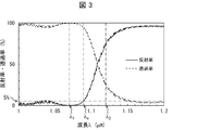
- FIG. 3 is a graph showing reflection characteristics and transmission characteristics of the short pass filter 111 provided in the glass block 11.
- the direction parallel to the central axis of the delivery fiber 21 and the central axis of the glass block 11 is defined as the z-axis direction.
- An arbitrary direction among the orthogonal directions is defined as an x-axis direction, and a direction orthogonal to each of the x-axis and the z-axis is defined as a y-axis direction.
- the direction from the incident surface 11i of the glass block 11 to the exit surface 11o is defined as the z-axis positive direction, and the right-handed orthogonal coordinate system is configured together with the z-axis positive direction.
- the z-axis positive direction is also referred to as the forward direction
- the z-axis negative direction is also referred to as the reverse direction. This is because in the fiber laser system FLS (see FIG. 5) described in the second embodiment, the output laser light propagates along the positive z-axis direction.
- the output head 1 includes a glass block 11, a delivery fiber 21, a glass tube 31, and an outer cylinder 41.
- a clad mode stripper 22 is provided at an intermediate portion of the delivery fiber 21.
- the output head 1 has an optical fiber termination structure that terminates an output side end of the optical fiber.
- the output side end of the output delivery fiber ODF provided in each of the fiber laser system FLS and the fiber laser apparatus FLA is provided.
- Each of the output head 1 and the delivery fiber 21 shown in FIG. 1A includes an output head OH and an output delivery fiber ODF provided in each of the fiber laser system FLS and the fiber laser apparatus FLA shown in FIG.
- the glass block 11 is made of glass having a high transmittance in a wavelength region including the wavelength ⁇ 1 of the output laser light (that is, having a low absorption rate) and a high melting point. Further, the glass material constituting the glass block 11 may have a high transmittance even in a wavelength region including the wavelength ⁇ 2 of Stokes light that can be generated as the output laser light having high intensity propagates through the delivery fiber 21. preferable.
- 1.07 ⁇ m is adopted as the wavelength ⁇ 1 .
- the wavelength ⁇ 2 is 1.12 ⁇ m.
- the material constituting the glass block 11 is preferably quartz (also called quartz).
- the shape of the glass block 11 is a cylinder as shown in FIGS.
- the glass block 11 has a diameter of 9 mm and an axial length of 20 mm.
- one bottom surface is defined as an incident surface 11i and the other bottom surface is defined as 11o.
- the incident surface 11i is located on the z-axis negative direction side
- the exit surface 11o is located on the z-axis positive direction side.
- the shape of the glass block 11 is not limited to a column,
- the shape (columnar shape) which looks like a cylinder may be sufficient as a macro, a prism may be sufficient, (( A truncated cone may be used as shown in a). That is, the shape of the glass block 11 may be any shape as long as it is columnar.
- each FS propagates in the forward direction in the glass block 11 while expanding at a predetermined angle.
- output surface 11o is configured to exceed the reflectance reflectance with respect to the output laser beam L FO for the Stokes light L FS.
- a short pass filter 111 having a reflectivity with respect to the Stokes light L FS higher than a reflectivity with respect to the output laser light L FO is laminated on the emission surface 11o.
- the short pass filter 111 corresponds to the layered filter described in the claims.
- the short pass filter 111 is referred to as SPF 111.
- the short pass filter is a filter that transmits light having a shorter wavelength than a predetermined wavelength (for example, a cutoff wavelength ⁇ c ) and reflects light having a longer wavelength than the predetermined wavelength among filters called edge filters. It is.
- the SPF 111 preferably has reflection characteristics (wavelength dependence of reflectance) and transmission characteristics (wavelength dependence of transmittance) as shown in FIG.
- the absorption rate of the SPF 111 can be regarded as zero, the sum of the reflectance and the transmittance is 1.
- the SPF 111 is configured by laminating a plurality of dielectric films. That is, the SPF 111 is composed of a dielectric multilayer film. By controlling the dielectric constant and film thickness of each dielectric film, a short pass filter having desired reflection characteristics can be designed.
- SPF111 is a reflectance for the Stokes light L FS 10% or more, and a reflectance for the output laser beam L FO is 2% or less.
- the cut-off wavelength ⁇ c of the SPF 111 is preferably located between the wavelength ⁇ 1 and the wavelength ⁇ 2 .
- the cutoff wavelength ⁇ c means a wavelength at which the reflectance of the SPF 111 is 5%.
- the cut-off wavelength ⁇ c of the SPF 111 shown in FIG. 3 is approximately 1.09 ⁇ m. SPF111 has an edge reflectance in the wavelength region of the longer wavelength side in the wavelength range near the cutoff wavelength lambda c is increased sharply.
- the SPF 111 having the reflection characteristics shown in FIG. 3 has a reflectance corresponding to the wavelength ⁇ 1 of 0.1% and a reflectance for the wavelength ⁇ 2 of 72.1%. Therefore, the SPF 111 transmits (1) almost all of the output laser light L FO as it is, (2) 72.1% of the Stokes light L FS is reflected as the return Stokes light L RS , and (3) the Stokes light L FS. 27.9% of the light is transmitted as Stokes light LFS ′ .
- the output laser beam LFO is provided to suppress reflection in the reverse direction on the exit surface of the glass block or the surface of the output coupler, and is a so-called anti-reflection (AR) film. It is. AR film reduces the reflectance to light included in a wide wavelength range, for increasing the transmittance, the output laser beam L FO and Stokes light L FS Tonouchi Stokes light L FS selectively be reflected more strongly Can not.
- the diameter of the spot S RS of the return Stokes light L RS on the incident surface 11i is twice the diameter of the spot of the Stokes light L FS on the output surface 11o. For example, if the spot diameter of the Stokes light L FS in the exit surface 11o (spot diameter) is 1.7 mm, the spot S RS diameter (spot diameter) it becomes 3.4 mm.
- the delivery fiber 21 is a double clad fiber including a core 211, an inner clad 212, and an outer clad 213.
- a multimode fiber is used as the delivery fiber 21.
- the core 211, the inner cladding 212, and the outer cladding 213 are all made of quartz.
- the exit surface 21o which is one end surface of the delivery fiber 21 is fused in a state of being abutted against the entrance surface 11i. That is, the entrance surface 11i and the exit surface 21o are optically coupled.
- coupling when the term “coupling” is used without particular notice, it means “optical coupling”.
- a removal section I in which the outer cladding 213 is removed is provided in the middle portion of the delivery fiber 21.
- a cladding mode stripper 22 is provided in the removal section I.
- the intermediate portion of the delivery fiber 21 means a portion excluding both ends of the delivery fiber 21.
- the removal section I may be provided in any portion as long as it is a portion excluding both ends of the delivery fiber 21. However, the removal section I is preferably provided in the vicinity of the exit surface 21o in terms of removing the return Stokes light L RS (see FIG. 1B) described later at an early stage.
- the cladding mode stripper 22 includes a high refractive index resin body 221 that covers the inner cladding 212 in the removal section I, and a reinforcing member 222 that supports the high refractive index resin body 221. Yes.
- the reinforcing member 222 is a rectangular parallelepiped block having a V-shaped groove formed on the upper surface.
- the reinforcing member 222 is made of an opaque material such as alumina.
- Alumina is suitable as a material for the reinforcing member 222 because it has good thermal conductivity, a low coefficient of linear expansion, and good workability.
- the high refractive index resin body 221 is obtained by curing a resin having a high refractive index injected into the V-shaped groove of the reinforcing member 222, for example.
- the high refractive index resin body 221 is made of a translucent resin having a refractive index equal to or higher than the refractive index of the inner cladding 212 of the delivery fiber 21 in the removal section I.
- the clad mode stripper 22 configured in this manner removes light (for example, Stokes light L FS and return Stokes light L RS ) coupled to the inner cladding 212 and the outer cladding 213 from the modes propagating through the delivery fiber 21. can do.
- light for example, Stokes light L FS and return Stokes light L RS
- the clad mode stripper 22 is adopted as an example of the clad mode stripper.
- the clad mode stripper provided in the output head 1 is not limited to the clad mode stripper 22 and may be any clad mode stripper.
- the glass tube 31 is a columnar glass member, and is made of quartz in the present embodiment.
- the glass tube 31 is provided in a section of the delivery fiber 21 from the emission surface 21 o of the delivery fiber 21 to the cladding mode stripper 22. In this section, the inner wall surface of the glass tube 31 is in contact with the surface of the delivery fiber 21 (the surface of the outer cladding 213) and covers the surface of the delivery fiber 21.
- the glass tube 31 is fixed by shrink fitting to the delivery fiber 21.
- the glass tube 31 before being fixed to the delivery fiber 21 is configured such that its inner diameter exceeds the outer diameter of the delivery fiber 21.
- Glass tube 31, when it is shrink-fitted against the delivery fiber 21, (1) is heated to a temperature above the glass transition point T g of the own and heated to a temperature above (2)
- Glass transition point T g remain, passed through a delivery fiber 21 on the inside of its cylinder, (3) with respect to its outer surface 313, it is under pressure, is cooled to a temperature below (4) a glass transition temperature T g.
- the glass tube 31 and the delivery fiber 21 are fixed in a state where the inner wall of the glass tube 31 is in close contact with the surface of the delivery fiber 21.
- the glass tube 31 is coupled to the glass block 11 via an end surface 311 which is one end surface thereof. More specifically, the end surface 311 is fused to the entrance surface 11i together with the exit surface 21o. Further, as shown in FIG. 2A, the glass tube 31 is coupled to the high refractive index resin body 221 of the cladding mode stripper 22 through an end surface 312 which is the other end surface.
- the high refractive index resin body 221 will be described later.
- the outer diameter of the glass tube 31 is preferably greater than the spot diameter of the spot S RS. Moreover, it is preferable that the end surface 311 is couple
- the outer surface 313 of the glass tube 31 has a concavo-convex structure that scatters at least Stokes light among the output laser light LFO and Stokes light. That is, it is preferable that the outer surface 313 is roughened into a ground glass shape.
- the Stokes light referred to here includes both the Stokes light LFS and the return Stokes light LRS .
- the outer cylinder 41 is a cylindrical glass member that houses the glass block 11, the delivery fiber 21, and the glass tube 31, and functions as a casing of the output head 1. To do.
- the outer cylinder 41 is made of quartz.
- the reinforcing member 222 of the cladding mode stripper 22 is illustrated as floating in the air inside the outer cylinder 41.
- FIG. 2B the actual reinforcing member 222 is fixed in a state where the two vertices 2221 and 2222 (see FIG. 2B) located on the negative side in the y-axis direction are in contact with the inner wall 411 of the outer cylinder 41.
- the load applied to the fusion point where the emission surface 21o of the delivery fiber 21 and the end surface 311 of the glass tube 31 and the incident surface 11i of the glass block 11 are fused can be greatly reduced.
- the glass block 11 outputs the laser beam L FO supplied from the delivery fiber 21 (the laser beam described in the claims). ) From the exit surface 11o.
- the reflectance with respect to the Stokes light L FS corresponding to the output laser beam L FO is configured to exceed the reflectivity for outputting the laser beam L FO.
- the output laser beam L FO and Stokes light L FS incident on the incident surface 11i propagates the inside of the glass block 11 while spreading at a predetermined angle determined by the numerical aperture of the delivery fiber 21, output surface 11o is reached.
- the exit surface 11o the reflectance with respect to the Stokes light L FS is configured to exceed the reflectivity for outputting the laser beam L FO. Therefore, among the emission output laser beam reaches the surface 11o L FO and Stokes light L FS, Stokes light L FS is reflected more strongly than the output laser beam L FO at the exit surface 11o a return Stokes beam L RS.
- Part of the return Stokes beam L RS is after propagated to the incident surface 11i from the exit surface 11o, it can bind to the core 211.
- the return Stokes beam L RS Stokes light coupled to the core of the delivery fiber that the (Stokes light propagating in the core 211 in other words in the opposite direction, not shown in FIG. 1 (b)) This is referred to as first return Stokes light.
- first return Stokes light because many of the return Stokes beam L RS, dissipated without binding to the core 211 of the delivery fiber 21. Therefore, even if the exit surface 11o is constructed so that the reflectance for the Stokes light L FS exceeds the reflectivity for outputting the laser beam L FO, the intensity of the first return Stokes light becomes extremely low .
- the Stokes light L FS is reflected more strongly than the output laser light L FO on the exit surface 11o of the glass block among the output laser light L FO and the Stokes light L FS . Therefore, compared with the conventional glass block, the glass block 11 can suppress the intensity
- the output laser beam L FO and the Stokes beam L FS ′ are focused by a spatial optical system (not shown in FIG. 5) and then the workpiece W, which is a workpiece, is processed. Irradiate the surface.
- the Stokes light LFS ′ irradiated on the surface of the workpiece W is reflected on the surface of the workpiece W.
- a part of the Stokes light LFS ′ reflected on the surface of the workpiece W can be refocused by the spatial optical system and can be coupled to the core 211 after propagating from the exit surface 11o to the entrance surface 11i.
- the Stokes light LFS ′ caused by the Stokes light coupled to the core 211 is a second. This is called return Stokes light.
- the intensity of the second return Stokes beam is proportional to the reflectance for the Stokes light L FS 'of the surface of the workpiece, and is proportional to the square of the transmittance for the Stokes light L FS of the exit surface 11o. Therefore, lowering the transmittance for the Stokes light L FS emission surface 11o, in other words, to increase the reflectance for the Stokes light L FS of the exit surface 11o is to reduce the intensity of the second return Stokes beam means. Therefore, compared with the case where the conventional glass block is used, the intensity of the second return Stokes light when the glass block 11 is used is clearly reduced.
- the glass block 11 can reduce the intensity of the second return Stokes light without substantially increasing the intensity of the first return Stokes light. Therefore, the glass block 11 can reduce the sum of the intensity of the first return Stokes light and the intensity of the second return Stokes light as compared with the conventional glass block, and thus Stokes oscillation occurs. The possibility can be reduced.
- the present glass block can be made compact as compared with the case where the demultiplexing element is provided separately.
- the present glass block can provide a more compact glass block while reducing the possibility of occurrence of Stokes oscillation.
- the glass block 11 has a secondary effect that it is maintenance-free.
- the laser head shown in FIG. 1 of Patent Document 3 includes a spatial optical system including a demultiplexing element.
- the glass block 11 does not include a spatial optical system.
- the glass block 11 is configured such that the exit surface 11o, which is one end surface of the columnar glass block 11, satisfies the above-described predetermined condition. Since the emission surface 11o cannot move, the glass block 11 is maintenance-free.
- an SPF 111 (a layered filter described in claims) having a reflectivity with respect to the Stokes light L FS higher than a reflectivity with respect to the output laser light L FO is laminated on the emission surface 11o.
- SPF111 is a reflectance for the Stokes light L FS 10% or more, reflectance to output the laser beam L FO is 2% or less, it is preferable.
- the cutoff wavelength ⁇ c of the SPF 111 is located between the wavelength ⁇ 1 corresponding to the output laser light L FO and the wavelength ⁇ 2 corresponding to the Stokes light L FS .
- the Stokes beam L FS ′ that passes through the emission surface 11o and reaches the workpiece is reliably suppressed. can do.
- (1) is reflected or scattered in the work
- (2) by passing through the forward and reverse path, you are possible to reliably suppress the intensity of the return Stokes beam L RS to again bind the delivery fiber 21. That is, the possibility of occurrence of Stokes oscillation can be reliably reduced.
- the output head 1 (the optical fiber termination structure described in the claims) includes a glass block 11 and a delivery fiber 21 in which an exit surface 21o is optically coupled to an entrance surface 11i.
- the output head 1 configured as described above has the same effect as the glass block 11.
- the delivery fiber 21 includes a clad mode stripper 22 provided at an intermediate portion thereof.
- the output head 1 can further reduce the possibility that Stokes oscillation will occur.
- the delivery fiber 21 includes the clad mode stripper 22, the demultiplexing element and unnecessary light included in the laser head shown in FIG. 1 of Patent Document 3 (replaced by the output head 1 of the present specification). There is no need to provide a propagation optical fiber and an unnecessary light processing unit. Therefore, the output head 1 can be made more compact than the laser head shown in FIG.
- a cylindrical glass tube 31 provided in a section from the emission surface 21 o of the delivery fiber 21 to the cladding mode stripper 22 and covering the surface of the outer cladding 213 of the delivery fiber 21.
- the glass tube 31 is coupled to the glass block 11 through an end surface 311 that is one end surface thereof, and is coupled to the cladding mode stripper 22 through an end surface 312 that is the other end surface. preferable.
- the return Stokes light L RS coupled to the glass tube 31 (at least a part of the return Stokes light L RS not coupled to the delivery fiber 21 again) propagates through the glass tube 31 in the reverse direction and reaches the cladding mode stripper 22. Finally, it is removed by the cladding mode stripper 22. Therefore, the output head 1 can be reliably remove at least a portion of not again coupled to the delivery fiber 21 return Stokes beam L RS.
- the outer diameter of the glass tube 31 is above the spot diameter of reaching the entrance surface 11i after reflected by the exit surface 11o return Stokes beam L RS (diameter of the spot S RS), the end surface 311 of the glass tube 31 is
- the glass block 11 is preferably bonded so as to include the spot SRS .
- the glass tube 31 is reflected at the exit surface 11o, binds to most again did not bind return Stokes beam L RS to the delivery fiber 21 (all ideally). Therefore, the output head 1, most of the newly unbound return Stokes beam L RS to the delivery fiber 21 (ideally all) can be reliably removed.
- the outer surface 313 of the glass tube 31 has an uneven structure that scatters at least Stokes light among the output laser light LFO and Stokes light (Stokes light LFS and return Stokes light LRS ). preferable.
- At least a part of the return Stokes light L RS coupled to the glass tube 31 can be dissipated to the outside of the glass tube 31.
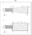
- FIGS. 4A and 4B are a cross-sectional view of a first modification and a cross-sectional view of a second modification of the glass block shown in FIG. 1, respectively.
- the glass block 11 of the first modification is obtained by reducing the diameter of the incident surface 11i of the glass block.
- the diameter of the incident surface 11 i is equal to the outer diameter of the glass tube 31.
- the entrance surface 11i and the exit surface 11o are arranged so as to be concentric.
- the glass block 11 of the first modification is configured such that the area of the incident surface 11i is less than the area of the exit surface 11o.
- the glass block 11 of the first modification has a truncated cone shape with the incident surface 11i as the upper bottom surface and the emission surface 11o as the lower bottom surface.
- the volume in the vicinity of the incident surface of the glass block 11 of the first modification can be reduced. Therefore, since the heat capacity in the vicinity of the incident surface of the glass block 11 can be reduced, the fusion can be easily performed when the fusion is adopted as a method for joining the glass block 11 and the delivery fiber 21. .
- the glass block 11 of the second modified example combines the outer surface 11s of the surfaces of the glass block 11 and the end surface 311 of the glass tube 31 of the incident surface 11i.
- the metal film 12 is further provided in a region excluding the region where the region is formed.
- the region where the end surface 311 is coupled includes the region where the emission surface 21 o of the delivery fiber 21 is coupled. Therefore, the metal film 12 is not formed in the region where the emission surface 21o is coupled.
- the region where the exit surface 21o is coupled is rephrased as the region where the exit surface 21o is scheduled to be coupled.
- the metal film 12 is laminated on the entire surface of the glass block 11 except for the region where the short pass filter 111 is laminated and the region where the end surface 311 of the glass tube 31 is bonded. ing. Therefore, the Stokes light L RS can be prevented from leaking outside the glass block 11. Therefore, it is possible to heat caused by the Stokes light L RS is reduce or eliminate the possibility of influencing the outside (ie, the output head 1) of the glass block 11.
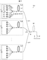
- FIG. 5 is a configuration diagram of the fiber laser system FLS.
- the fiber laser system FLS includes an output head OH (that is, the output head 1 shown in FIG. 1A) according to an embodiment of the present invention.
- the fiber laser system FLS is a laser device for processing a workpiece W that is a processing target.
- n fiber laser units FLU1 to FLUn, n laser delivery fibers LDF1 to LDFn, An output combiner OC, an output delivery fiber ODF, and an output head OH are provided.
- the fiber laser units FLU1 to FLUn and the laser delivery fibers LDF1 to LDFn correspond one to one.
- n is an arbitrary natural number of 1 or more, and represents the number of fiber laser units FLU1 to FLUn and laser delivery fibers LDF1 to LDFn.
- the output combiner OC is an aspect of the multiplexing unit described in the claims, and includes n input ports and one output port.
- the output combiner OC combines n laser beams input to each input port into one laser beam, and outputs the combined laser beam from the output port.
- Each of the output delivery fiber ODF and the output head OH of the fiber laser system FLS corresponds to the delivery fiber 21 and the output head 1 shown in FIG.
- the fiber laser unit FLUI (i is a natural number between 1 and n) generates laser light.
- forward-pumped fiber lasers are used as the fiber laser units FLU1 to FLUn.
- the fiber laser unit FLUi is connected to the input end of the corresponding laser delivery fiber LDFi.
- the laser beam generated by the fiber laser unit FLUi is input to the laser delivery fiber LDFi.
- the laser delivery fiber LDFi guides the laser light generated by the corresponding fiber laser unit FLUi.
- the laser delivery fibers LDF1 to LDFn may be single mode fibers or fu mode fibers having 10 or less modes.
- the fu mode fiber is used as the laser delivery fibers LDF1 to LDFn.
- the output end of the laser delivery fiber LDFi is connected to the input port of the output combiner OC.
- the laser light generated by the fiber laser unit FLUi and guided through the laser delivery fiber LDFi is input to the output combiner OC through this input port.
- the output combiner OC is generated by each of the fiber laser units FLU1 to FLUn, and combines the laser beams guided by the laser delivery fibers LDF1 to LDFn.
- the output port of the output combiner OC is connected to the input end of the output delivery fiber ODF.
- the laser beam combined by the output combiner OC is input to the output delivery fiber ODF. That is, the incident surface of the output delivery fiber ODF is coupled to a plurality of fiber laser units FLUi via the output combiner OC.
- the output delivery fiber ODF guides the laser beam combined by the output combiner OC.
- a multimode fiber is used as the output delivery fiber ODF.
- the output end of the output delivery fiber ODF is connected to the output head OH.
- a spatial optical system for example, a convex lens, not shown in FIG. 5 for focusing the laser beam emitted from the output head OH on the surface of the work W is provided between the output head OH and the work W. ing.
- the laser beam combined by the output combiner OC is emitted from the output head OH, and is irradiated onto the workpiece W in a state of being focused by the spatial optical system.
- the output combiner OC is adopted as an example of the multiplexing unit described in the claims.
- a spatial optical system including a plurality of convex lenses can be employed as an example of the combining unit recited in the claims.
- this spatial optical system is composed of n convex lenses, each convex lens focuses the laser beam emitted from the laser delivery fiber LDFi of each fiber laser unit FLUi and outputs each focused laser beam. What is necessary is just to be arrange
- the configuration of the fiber laser unit FLU1 provided in the fiber laser system FLS will be described with reference to FIG.
- the fiber laser units FLU2 to FLUn are configured in the same manner as the fiber laser unit FLU1.
- the fiber laser unit FLU1 is a forward pumping type fiber laser, and as shown in FIG. 5, m pumping light sources PS1 to PSm, m pumping delivery fibers PDF1 to PDFm, pumping combiner PC, and high reflection fiber Bragg A grating FBG-HR, an amplification fiber AF, and a low reflection fiber Bragg grating FBG-LR are provided. That is, the fiber laser unit FLU1 is a resonator type fiber laser unit.
- the excitation light sources PS1 to PSm and the excitation delivery fibers PDF1 to PDFm correspond one to one.
- m is an arbitrary natural number of 2 or more, and represents the number of excitation light sources PS1 to PSm and excitation delivery fibers PDF1 to PDFm.
- the excitation light source PSj (j is a natural number between 1 and m) generates excitation light.
- laser diodes are used as the excitation light sources PS1 to PSm.
- the excitation light source PSj is connected to the input end of the corresponding excitation delivery fiber PDFj. Excitation light generated by the excitation light source PSj is input to the excitation delivery fiber PDFi.
- the excitation delivery fiber PDFj guides the excitation light generated by the corresponding excitation light source PSj.
- the output end of the excitation delivery fiber PDFj is connected to the input port of the excitation combiner PC.
- the excitation light generated by the excitation light source PSj and guided through the excitation delivery fiber PDFj is input to the excitation combiner PC via this input port.
- the excitation combiner PC multiplexes the excitation light generated by each of the excitation light sources PS1 to PSm and guided through each of the excitation delivery fibers PDF1 to PDFm.
- the output port of the excitation combiner PC is connected to the input end of the amplification fiber AF via the high reflection fiber Bragg grating FBG-HR.
- the excitation light transmitted through the highly reflective fiber Bragg grating FBG-HR is input to the amplification fiber AF.
- the amplification fiber AF generates laser light using the excitation light that has passed through the highly reflective fiber Bragg grating FBG-HR.
- the excitation light transmitted through the highly reflective fiber Bragg grating FBG-HR is used to maintain this rare earth element in an inverted distribution state.
- the output end of the amplification fiber AF is connected to the input end of the laser delivery fiber LDF1 via the low reflection fiber Bragg grating FBG-LR.
- the high reflection fiber Bragg grating FBG-HR functions as a mirror at a certain wavelength ⁇ (for example, 1060 nm) (reflectance becomes 99%, for example), and the low reflection fiber Bragg grating FBG-LR serves as a half mirror at the wavelength ⁇ . Function (reflectance becomes 10%, for example).
- the amplification fiber AF together with the high reflection fiber Bragg grating FBG-HR and the low reflection fiber Bragg grating FBG-LR, constitutes a resonator that oscillates laser light of wavelength ⁇ .
- the laser light transmitted through the low reflection fiber Bragg grating FBG-LR is input to the laser delivery fiber LDF1.
- forward-pumped fiber lasers are used as the fiber laser units FLU1 to FLUn, but the present invention is not limited to this. That is, in the present invention, backward pumping type fiber lasers can be used as the fiber laser units FLU1 to FLUn, and bidirectional pumping fiber lasers can be used as the fiber laser units FLU1 to FLUn.
- the fiber laser system FLS configured in this manner has the same effects as the glass block 11 and the output head 1 described in the first embodiment.
- the fiber laser system FLS employs a resonator type fiber laser unit as each of the fiber laser units FLU1 to FLUn which are laser units described in the claims.
- the fiber laser system FLS can adopt a MOPA type fiber laser unit as each of the fiber laser units FLU1 to FLUn.
- the MOPA type fiber laser unit includes a main oscillation (Master Oscillator: MO) unit and a power amplification (Power Amplifier: PA) unit arranged at a subsequent stage of the MO unit.
- the MO unit generates seed light
- the PA unit generates laser light by amplifying the power of the seed light.
- the MO unit may be a resonator type fiber laser unit, or any one of a semiconductor laser unit, a solid state laser unit, a liquid laser unit, and a gas laser unit. Also good.
- the fiber laser system LFS may employ any one of a semiconductor laser unit, a solid-state laser unit, a liquid laser unit, and a gas laser unit as the laser unit described in the claims.
- FIG. 6 is a configuration diagram of the fiber laser apparatus FLA.
- the fiber laser apparatus FLA includes a fiber laser unit FLU1 and an output head OH (that is, the output head 1 shown in FIG. 1A) according to an embodiment of the present invention.
- the fiber laser unit FLU1 provided in the fiber laser apparatus FLA has the same configuration as the fiber laser unit FLU1 provided in the fiber laser system FLS (see FIG. 5). Therefore, in this embodiment, the description of the fiber laser unit FLU1 is omitted.
- the fiber laser apparatus FLA does not need to multiplex laser beams generated by each of the plurality of fiber laser units FLU1 to FLUn. Therefore, the fiber laser apparatus FLA can omit the output combiner OC included in the fiber laser system FLS. As a result, in the fiber laser apparatus FLA, the incident end face of the output delivery fiber ODF is coupled to the fiber laser unit FLU1. As in the case of the fiber laser system FLS, the fiber laser apparatus FLA may employ a resonator type fiber laser unit or a MOPA type fiber laser unit as the fiber laser unit FLU1. Good.
- the MO unit may be a resonator type fiber laser unit, a semiconductor laser unit, a solid state laser unit, a liquid Either a laser unit or a gas laser unit may be used.
- the fiber laser apparatus FLA may employ any one of a semiconductor laser unit, a solid-state laser unit, a liquid laser unit, and a gas laser unit as the laser unit described in the claims.
- the fiber laser apparatus FLA configured as described above has the same effects as the glass block 11 described in the first embodiment, the output head 1, and the fiber laser apparatus FLA described in the second embodiment. .
- the incident end face of the output delivery fiber ODF included in the output head 1 is connected to at least one of the fiber laser units FLU1 to FLUn via the output combiner OC.
- the fiber laser units FLU1 can be coupled to one fiber laser unit FLU1.
- the glass block (11) has an exit surface (21o) of a delivery fiber (21) with respect to the entrance surface (11i), with both bottom surfaces as an entrance surface (11i) and an exit surface (11o). ) Are optically coupled to each other, a columnar glass block (11) for emitting laser light supplied from the delivery fiber (21) from the emission surface (11o), the emission surface (11o) being The reflectance with respect to the Stokes light corresponding to the laser light is higher than the reflectance with respect to the laser light.
- the output surface of a glass block is comprised so that the reflectance with respect to Stokes light may exceed the reflectance with respect to a laser beam. Therefore, of the laser light and Stokes light that has reached the exit surface of the glass block, the Stokes light is reflected more strongly than the laser light on the exit surface of the glass block.
- a portion of the Stokes light reflected by the exit surface of the glass block can be coupled to the core of the delivery fiber after propagating from the exit surface of the glass block to the entrance surface.
- Stokes light (in other words, Stokes light propagating in the reverse direction through the delivery fiber) coupled to the core of the delivery fiber due to the Stokes light reflected on the exit surface of the glass block is referred to as the first return Stokes. Called light.
- the intensity of the first return Stokes light is extremely low.
- the Stokes light is reflected more strongly than the laser light on the exit surface of the glass block. Therefore, the intensity of the Stokes light emitted from the exit surface of the main glass block is suppressed compared to a glass block whose exit surface is configured such that the reflectivity for Stokes light is equal to or less than the reflectivity for laser light. ing.
- a part of the Stokes light emitted from the exit surface of the glass block is reflected on the surface of the workpiece and can be coupled to the core of the delivery fiber after propagating from the exit surface of the glass block to the entrance surface.
- the Stokes light coupled to the core of the delivery fiber due to the Stokes light emitted from the exit surface of the glass block is referred to as the second return Stokes. Called light.
- the second return Stokes the Stokes light coupled to the core of the delivery fiber due to the Stokes light emitted from the exit surface of the glass block
- the second return Stokes the Stokes light propagating in the reverse direction through the delivery fiber
- the intensity of the second return Stokes light is proportional to the reflectance with respect to the Stokes light on the surface of the workpiece, and is proportional to the square of the transmittance with respect to the Stokes light on the exit surface of the glass block. Therefore, reducing the transmittance of the exit surface of the glass block with respect to the Stokes light, in other words, increasing the reflectivity of the exit surface with respect to the Stokes light means that the intensity of the second return Stokes light is reduced. .
- the present glass block can reduce the intensity of the second return Stokes light without substantially increasing the intensity of the first return Stokes light as compared with the conventional glass block. Therefore, since the present glass block can reduce the sum of the intensity of the first return Stokes light and the intensity of the second return Stokes light as compared with the conventional glass block, Stokes oscillation occurs. The possibility can be reduced.
- the present glass block can be made compact as compared with the case where the demultiplexing element is provided separately.
- the present glass block can provide a more compact glass block while reducing the possibility of occurrence of Stokes oscillation.
- this glass block has a secondary effect of being maintenance-free.
- the laser head shown in FIG. 1 of Patent Document 3 includes a spatial optical system including a demultiplexing element.
- the present glass block does not include a spatial optical system.
- the present glass block is configured such that the emission end face, which is one end face of the columnar glass block, satisfies the above-described predetermined condition. Since one end surface of the columnar glass block cannot move, the glass block is maintenance-free.
- a layered filter (111) having a reflectance with respect to the Stokes light that exceeds the reflectance with respect to the laser light is stacked on the emission surface (11o). Is preferable.
- the possibility of occurrence of Stokes oscillation can be reduced without increasing the volume of the glass block.
- the layered filter (111) has a reflectance with respect to the Stokes light of 10% or more and a reflectance with respect to the laser light of 2% or less. It is preferable.
- the cutoff wavelength of the layered filter (111) is located between a wavelength corresponding to the laser light and a wavelength corresponding to the Stokes light. It is preferable.
- the reflection coefficient or the cut-off wavelength for laser light and Stokes light as described above, Stokes light that passes through the exit surface of the glass block and reaches the workpiece can be reliably suppressed. Therefore, (1) the intensity of the Stokes light that is reflected or scattered by the workpiece and (2) rejoins with the delivery fiber can be reliably suppressed by passing through the path opposite to the forward path. That is, the possibility of occurrence of Stokes oscillation can be reliably reduced.
- the cut-off wavelength means a wavelength at which the reflection coefficient is 5%.
- the area of the incident surface (11i) is configured to be smaller than the area of the emission surface (11o).
- the volume in the vicinity of the incident surface of the glass block can be reduced. Therefore, since the heat capacity in the vicinity of the incident surface of the glass block can be reduced, the fusion can be easily performed when the fusion is adopted as a method for coupling the glass block and the delivery fiber.
- the said metal film (12) is laminated on at least a part of the surface excluding the region where the emission surface (21o) of the delivery fiber (21) is planned to be coupled.
- An optical fiber termination structure (1) includes an exit surface with respect to the glass block (11) according to any one aspect described above and the incident surface (11i) of the glass block (11). (21o) and an optically coupled delivery fiber (21).
- the Stokes light is Stokes light generated as the laser light propagates through the delivery fiber (21).
- this optical fiber termination structure has an effect similar to the glass block which concerns on each aspect mentioned above.
- the delivery fiber (21) includes a clad mode stripper (22) provided at an intermediate portion thereof.
- Stokes light also referred to as clad mode
- this optical fiber termination structure can further reduce the possibility of occurrence of Stokes oscillation.
- the delivery fiber includes the cladding mode stripper, the demultiplexing element and unnecessary light included in the laser head shown in FIG. 1 of Patent Document 3 (which can be read as the output head 1 described in claims).
- the optical fiber termination structure can be made more compact than the laser head described in FIG.
- An optical fiber termination structure (1) is provided in a section from the emission surface (21o) of the delivery fiber (21) to the cladding mode stripper (22).
- 21) is further provided with a cylindrical glass tube (31) that covers the surface of the clad (213) provided in the glass block (31) via the one end surface (311) of the glass block (11).
- a glass tube couple
- Stokes light coupled to the glass tube propagates in the reverse direction through the glass tube, reaches the cladding mode stripper, and is finally removed by the cladding mode stripper. . Therefore, this optical fiber termination structure can reliably remove at least a part of the Stokes light that has not been coupled to the delivery fiber.
- the glass tube (31) has an outer diameter reflected by the emission surface (11o) of the glass block (11) and then the glass.
- the spot diameter of the Stokes light that has reached the entrance surface (11i) of the block (11) exceeds the one end surface (311) of the glass tube (31), and the exit surface (11o) of the glass block (11). It is preferable that the glass block (11) is optically coupled so as to include the spot of the Stokes light that has reached.
- the glass tube is reflected on the exit surface of the glass block and is coupled with most of the Stokes light that has not been coupled to the delivery fiber again. Therefore, the present optical fiber termination structure can reliably remove most of the Stokes light that has not been re-coupled to the delivery fiber.
- the outer surface (313) of the glass tube (31) has at least unevenness that scatters the Stokes light among the laser light and the Stokes light. It is preferable that a structure is formed.
- part of the Stokes light propagating in the reverse direction coupled to the glass tube can be dissipated to the outside of the glass tube.
- a laser apparatus (FLA) includes a laser apparatus (FLU1) that emits laser light and the optical fiber termination structure (OH) according to any one aspect described above ( FLA), the incident surface of the delivery fiber (ODF) is optically coupled to the laser unit (FLU1), and the glass block (11) is emitted from the laser unit (FLU1).
- the laser beam supplied from the delivery fiber (ODF) is emitted from the emission surface (11o) of the glass block (11).
- a laser system (FLS) includes one or more laser units (FLU1 to FLUn) each emitting laser light, and each of the one or more laser units (FLU1 to FLUn) emitting light.
- a fiber laser system (FLS) comprising a multiplexing unit (OC) for combining the laser beams into one and the optical fiber termination structure (OH) according to any one of the above-described aspects,
- An incident surface of a fiber (ODF) is optically coupled to the multiplexing unit (OC), and the glass block (11) emits from each of the one or a plurality of laser units (FLU1 to FLUn).
- the laser beam combined by the multiplexing unit (OC) and supplied from the delivery fiber (ODF) is emitted from the glass block (11). Emitted from the surface (11o), and wherein the.
- each of the present laser device and the present laser system has the same effect as the glass block according to each aspect described above.
- the laser unit (FLU1) is a fiber laser unit including a plurality of excitation light sources (PS1 to PSm) and an amplification fiber (AF). It is preferable.
- each of the one or more laser units includes a plurality of excitation light sources (PS1 to PSm) and an amplification fiber (AF).
- PS1 to PSm excitation light sources
- AF amplification fiber
- the multiplexing unit (OC) is preferably a combiner including one or more input ports and one output port.
- One embodiment of the present invention is suitable for a laser apparatus or a laser system that employs a fiber laser unit as a laser unit as described above.
Landscapes
- Physics & Mathematics (AREA)
- Electromagnetism (AREA)
- Optics & Photonics (AREA)
- Engineering & Computer Science (AREA)
- Plasma & Fusion (AREA)
- General Physics & Mathematics (AREA)
- Lasers (AREA)
- Optical Couplings Of Light Guides (AREA)
Abstract
La présente invention concerne un bloc de verre plus compact qui réduit au maximum la possibilité d'oscillations de Stokes. Le bloc de verre (11), qui a la forme d'une colonne, émet une lumière laser à partir d'une surface d'émission (11o) lorsque la surface d'émission (21i) d'une fibre de distribution (21) est reliée à la surface d'incidence (11i) du bloc de verre. La surface d'émission (11o) du bloc de verre (11) est configurée de telle sorte que la réflectance par rapport à la lumière de Stokes est supérieure à la réflectance par rapport à la lumière laser.
Applications Claiming Priority (2)
| Application Number | Priority Date | Filing Date | Title |
|---|---|---|---|
| JP2018-085593 | 2018-04-26 | ||
| JP2018085593A JP6636562B2 (ja) | 2018-04-26 | 2018-04-26 | ガラスブロック、光ファイバ終端構造、レーザ装置、及びレーザシステム |
Publications (1)
| Publication Number | Publication Date |
|---|---|
| WO2019207902A1 true WO2019207902A1 (fr) | 2019-10-31 |
Family
ID=68295239
Family Applications (1)
| Application Number | Title | Priority Date | Filing Date |
|---|---|---|---|
| PCT/JP2019/004627 Ceased WO2019207902A1 (fr) | 2018-04-26 | 2019-02-08 | Bloc de verre, structure de terminaison de fibre optique, dispositif laser et système laser |
Country Status (2)
| Country | Link |
|---|---|
| JP (1) | JP6636562B2 (fr) |
| WO (1) | WO2019207902A1 (fr) |
Cited By (1)
| Publication number | Priority date | Publication date | Assignee | Title |
|---|---|---|---|---|
| CN113906288A (zh) * | 2019-12-13 | 2022-01-07 | 在线业务解决方案株式会社 | 圆筒内表面检查装置 |
Citations (8)
| Publication number | Priority date | Publication date | Assignee | Title |
|---|---|---|---|---|
| JPS63265206A (ja) * | 1987-04-23 | 1988-11-01 | Fujitsu Ltd | 光フアイバフイルタ |
| JPH0425804A (ja) * | 1990-05-21 | 1992-01-29 | Nippon Telegr & Teleph Corp <Ntt> | 光学接続構造 |
| JP2002006348A (ja) * | 2000-06-21 | 2002-01-09 | Mitsubishi Electric Corp | 光増幅器 |
| US20100329292A1 (en) * | 2008-01-31 | 2010-12-30 | Nkt Photonics A/S | System, device and method for stabilizing the optical output power of an optical system |
| JP2014513411A (ja) * | 2011-03-01 | 2014-05-29 | オーエフエス ファイテル,エルエルシー | 高次モードファイバを用いる超短パルスのファイバデリバリーのための方法、およびシステム |
| WO2015155994A1 (fr) * | 2014-04-10 | 2015-10-15 | アダマンド株式会社 | Assemblage de fibres optiques, et dispositif de liaison optique / dispositif de liaison de fibres optiques |
| US20170017036A1 (en) * | 2015-07-17 | 2017-01-19 | Spi Lasers Uk Limited | Apparatus for combining optical radiation |
| JP2017085042A (ja) * | 2015-10-30 | 2017-05-18 | 株式会社フジクラ | ファイバレーザシステム |
-
2018
- 2018-04-26 JP JP2018085593A patent/JP6636562B2/ja active Active
-
2019
- 2019-02-08 WO PCT/JP2019/004627 patent/WO2019207902A1/fr not_active Ceased
Patent Citations (8)
| Publication number | Priority date | Publication date | Assignee | Title |
|---|---|---|---|---|
| JPS63265206A (ja) * | 1987-04-23 | 1988-11-01 | Fujitsu Ltd | 光フアイバフイルタ |
| JPH0425804A (ja) * | 1990-05-21 | 1992-01-29 | Nippon Telegr & Teleph Corp <Ntt> | 光学接続構造 |
| JP2002006348A (ja) * | 2000-06-21 | 2002-01-09 | Mitsubishi Electric Corp | 光増幅器 |
| US20100329292A1 (en) * | 2008-01-31 | 2010-12-30 | Nkt Photonics A/S | System, device and method for stabilizing the optical output power of an optical system |
| JP2014513411A (ja) * | 2011-03-01 | 2014-05-29 | オーエフエス ファイテル,エルエルシー | 高次モードファイバを用いる超短パルスのファイバデリバリーのための方法、およびシステム |
| WO2015155994A1 (fr) * | 2014-04-10 | 2015-10-15 | アダマンド株式会社 | Assemblage de fibres optiques, et dispositif de liaison optique / dispositif de liaison de fibres optiques |
| US20170017036A1 (en) * | 2015-07-17 | 2017-01-19 | Spi Lasers Uk Limited | Apparatus for combining optical radiation |
| JP2017085042A (ja) * | 2015-10-30 | 2017-05-18 | 株式会社フジクラ | ファイバレーザシステム |
Cited By (1)
| Publication number | Priority date | Publication date | Assignee | Title |
|---|---|---|---|---|
| CN113906288A (zh) * | 2019-12-13 | 2022-01-07 | 在线业务解决方案株式会社 | 圆筒内表面检查装置 |
Also Published As
| Publication number | Publication date |
|---|---|
| JP2019192834A (ja) | 2019-10-31 |
| JP6636562B2 (ja) | 2020-01-29 |
Similar Documents
| Publication | Publication Date | Title |
|---|---|---|
| JP6140072B2 (ja) | レーザ装置および加工装置 | |
| EP0812039B1 (fr) | Source de lumière à fibre optique avec coupleur à fibre multimode | |
| WO2012099116A1 (fr) | Appareil du type laser à fibre et procédé d'alignement d'une position de rayonnement lumineux du laser | |
| JP6356856B1 (ja) | クラッドモード光除去構造及びレーザ装置 | |
| US20060098694A1 (en) | Optical fiber for fiber laser, fiber laser, and laser oscillation method | |
| JP5688565B2 (ja) | ファイバレーザ装置と光増幅方法 | |
| JP2021163814A (ja) | 光ファイバ増幅器および光通信システム | |
| JP7809691B2 (ja) | レーザ装置および加工装置 | |
| JP6357207B2 (ja) | 光ファイバ及びファイバレーザ | |
| US7106928B2 (en) | Coupling high power optical sources to small diameter fibers | |
| JP6423914B1 (ja) | クラッドモードストリッパ | |
| JP6636562B2 (ja) | ガラスブロック、光ファイバ終端構造、レーザ装置、及びレーザシステム | |
| WO2020162057A1 (fr) | Structure, procédé de fabrication de structure, dispositif laser et système laser | |
| JP2007250951A (ja) | ダブルクラッドファイバ及びそれを備えたファイバレーザ | |
| JP7300512B2 (ja) | 光増幅装置 | |
| US7724424B2 (en) | Optical module and optical amplification module | |
| JP4899705B2 (ja) | 光増幅モジュール | |
| WO2006098313A1 (fr) | Amplificateur optique et dispositif laser | |
| WO2020203136A1 (fr) | Dispositif laser à fibre | |
| JP5014640B2 (ja) | マルチモードファイバ、光増幅器及びファイバレーザ | |
| JP2007294534A (ja) | 光学的モジュール | |
| JP5202820B2 (ja) | 光結合器、ファイバレーザ及び光ファイバ増幅器 | |
| JP7189790B2 (ja) | 光ファイバレーザおよび合波型光ファイバレーザ | |
| WO2019172398A1 (fr) | Dispositif d'élimination de lumière en excès et laser à fibre | |
| JP2007123594A (ja) | 光ファイバ型光増幅装置及びこれを用いた光ファイバ型レーザ装置 |
Legal Events
| Date | Code | Title | Description |
|---|---|---|---|
| 121 | Ep: the epo has been informed by wipo that ep was designated in this application |
Ref document number: 19793018 Country of ref document: EP Kind code of ref document: A1 |
|
| NENP | Non-entry into the national phase |
Ref country code: DE |
|
| 122 | Ep: pct application non-entry in european phase |
Ref document number: 19793018 Country of ref document: EP Kind code of ref document: A1 |