WO2019207902A1 - ガラスブロック、光ファイバ終端構造、レーザ装置、及びレーザシステム - Google Patents
ガラスブロック、光ファイバ終端構造、レーザ装置、及びレーザシステム Download PDFInfo
- Publication number
- WO2019207902A1 WO2019207902A1 PCT/JP2019/004627 JP2019004627W WO2019207902A1 WO 2019207902 A1 WO2019207902 A1 WO 2019207902A1 JP 2019004627 W JP2019004627 W JP 2019004627W WO 2019207902 A1 WO2019207902 A1 WO 2019207902A1
- Authority
- WO
- WIPO (PCT)
- Prior art keywords
- laser
- glass block
- fiber
- light
- stokes
- Prior art date
- Legal status (The legal status is an assumption and is not a legal conclusion. Google has not performed a legal analysis and makes no representation as to the accuracy of the status listed.)
- Ceased
Links
Images



Classifications
-
- G—PHYSICS
- G02—OPTICS
- G02B—OPTICAL ELEMENTS, SYSTEMS OR APPARATUS
- G02B6/00—Light guides; Structural details of arrangements comprising light guides and other optical elements, e.g. couplings
- G02B6/24—Coupling light guides
- G02B6/26—Optical coupling means
- G02B6/32—Optical coupling means having lens focusing means positioned between opposed fibre ends
-
- G—PHYSICS
- G02—OPTICS
- G02B—OPTICAL ELEMENTS, SYSTEMS OR APPARATUS
- G02B6/00—Light guides; Structural details of arrangements comprising light guides and other optical elements, e.g. couplings
- G02B6/24—Coupling light guides
- G02B6/42—Coupling light guides with opto-electronic elements
-
- H—ELECTRICITY
- H01—ELECTRIC ELEMENTS
- H01S—DEVICES USING THE PROCESS OF LIGHT AMPLIFICATION BY STIMULATED EMISSION OF RADIATION [LASER] TO AMPLIFY OR GENERATE LIGHT; DEVICES USING STIMULATED EMISSION OF ELECTROMAGNETIC RADIATION IN WAVE RANGES OTHER THAN OPTICAL
- H01S3/00—Lasers, i.e. devices using stimulated emission of electromagnetic radiation in the infrared, visible or ultraviolet wave range
-
- H—ELECTRICITY
- H01—ELECTRIC ELEMENTS
- H01S—DEVICES USING THE PROCESS OF LIGHT AMPLIFICATION BY STIMULATED EMISSION OF RADIATION [LASER] TO AMPLIFY OR GENERATE LIGHT; DEVICES USING STIMULATED EMISSION OF ELECTROMAGNETIC RADIATION IN WAVE RANGES OTHER THAN OPTICAL
- H01S3/00—Lasers, i.e. devices using stimulated emission of electromagnetic radiation in the infrared, visible or ultraviolet wave range
- H01S3/05—Construction or shape of optical resonators; Accommodation of active medium therein; Shape of active medium
- H01S3/06—Construction or shape of active medium
- H01S3/063—Waveguide lasers, i.e. whereby the dimensions of the waveguide are of the order of the light wavelength
- H01S3/067—Fibre lasers
-
- H—ELECTRICITY
- H01—ELECTRIC ELEMENTS
- H01S—DEVICES USING THE PROCESS OF LIGHT AMPLIFICATION BY STIMULATED EMISSION OF RADIATION [LASER] TO AMPLIFY OR GENERATE LIGHT; DEVICES USING STIMULATED EMISSION OF ELECTROMAGNETIC RADIATION IN WAVE RANGES OTHER THAN OPTICAL
- H01S3/00—Lasers, i.e. devices using stimulated emission of electromagnetic radiation in the infrared, visible or ultraviolet wave range
- H01S3/10—Controlling the intensity, frequency, phase, polarisation or direction of the emitted radiation, e.g. switching, gating, modulating or demodulating
Definitions
- the present invention relates to a glass block capable of optically coupling a delivery fiber, an optical fiber termination structure including such a glass block and a delivery fiber, and a fiber laser system including such an optical fiber termination structure.
- a fiber laser system including a plurality of fiber laser units is used as a processing laser device.
- the laser light generated by each fiber laser unit and propagating through the laser delivery fiber of each fiber laser unit is combined into one output laser light in the output combiner, and the incident surface of the output delivery fiber Combined with An incident surface of a glass block (for example, the glass rod 63 described in FIG. 3 of Patent Document 1 or the coreless fiber described in FIG. 3 of Patent Document 2) is optically coupled to the output surface of the output delivery fiber. ing.
- the output laser light that has propagated through the output delivery fiber is emitted from the exit surface of the glass block, collected by an optical system interposed between the exit surface and the workpiece, and then irradiated onto the workpiece.
- Patent Document 1 describes a technique of reducing the reflectivity of output laser light on the exit surface by providing a dielectric multilayer film on the exit surface of the glass block.
- Patent Document 2 describes a technique in which a dielectric multilayer film having characteristics such that a part of laser light is reflected and the rest is transmitted on the surface of an output coupler.
- Japanese Patent Publication “JP 2012-68664 A” (April 5, 2012) Japanese Published Patent Publication "Japanese Patent Laid-Open No. 2005-303166” (October 27, 2005) Japanese Patent Publication “Japanese Patent Laid-Open No. 2016-186536” (released on October 27, 2016)
- the number of fiber laser units provided in the fiber laser system as described above and the rated output of each fiber laser unit vary. As an example, there is a fiber laser system that includes seven fiber laser units and each fiber laser unit has a rated output of 1 kW. That is, the rated output of this fiber laser system is 7 kW.
- FIG. 1 of Patent Document 3 describes a fiber laser device in which a demultiplexing element that demultiplexes unnecessary light and Raman light is disposed inside a laser head provided in a termination structure of an output delivery fiber.
- a demultiplexing element that demultiplexes unnecessary light and Raman light is disposed inside a laser head provided in a termination structure of an output delivery fiber.
- Each of the fiber laser device, unnecessary light, and Raman light can be read as the fiber laser system, output laser light, and Stokes light in this specification, respectively.
- the Stokes light transmitted through the demultiplexing element is applied to the workpiece, and unnecessary light reflected by the demultiplexing element is guided to the outside of the laser head by the unnecessary light propagation optical fiber and coupled to the unnecessary light processing unit.
- the unnecessary light processing unit converts the unnecessary light into heat and then processes the unnecessary light by diffusing the heat.
- the branching element described in Patent Document 3 is a bandpass filter that transmits Raman light and reflects unwanted light.
- a demultiplexing element is separately provided inside the laser head (optical fiber termination structure in the present specification), and unnecessary light is transmitted using an unnecessary light propagation fiber. It was necessary to guide the laser head outside. Therefore, this laser head has room for further miniaturization.
- the laser head is disposed in the vicinity of the workpiece. There is a desire to make the laser head as compact as possible in order to increase the degree of freedom during processing.
- One embodiment of the present invention has been made in view of the above-described problem, and an object thereof is to reduce the possibility of occurrence of Stokes oscillation, and to make a more compact glass block, optical fiber termination structure, laser device, and laser Is to provide a system.
- the glass block according to one aspect of the present invention has a bottom surface as an incident surface and an output surface, and the output surface of the delivery fiber is optically coupled to the incident surface.
- (A) is sectional drawing of the output head provided with the glass block which concerns on the 1st Embodiment of this invention.
- (B) is an expanded sectional view of the glass block shown to (a).
- (C) is the arrow view which looked at the glass block shown to (a) and (b) from the delivery fiber side.
- (A) is a longitudinal cross-sectional view of the cladding mode stripper with which the delivery fiber shown to (a) of FIG. 1 is equipped.
- (B) is a cross-sectional view of the cladding mode stripper shown in (a). It is a graph which shows the reflective characteristic and transmission characteristic of a short pass filter with which the glass block shown to (a) of FIG. 1 is provided.
- (A) And (b) is sectional drawing of the 1st modification of a glass block shown in FIG. 1, and sectional drawing of a 2nd modification, respectively. It is a block diagram of the fiber laser system provided with the output head shown in FIG. It is a block diagram of the fiber laser apparatus provided with the output head shown in FIG.
- FIG. 1A is a cross-sectional view of an output head 1 including a glass block 11 according to this embodiment.
- FIG. 1B is an enlarged cross-sectional view of the glass block 11.
- C of FIG. 1 is the arrow view which looked at the glass block 11 from the delivery fiber 21 side (z-axis negative direction side).
- FIG. 2A is a longitudinal sectional view of a clad mode stripper 22 provided in the delivery fiber 21.
- FIG. 2B is a cross-sectional view of the clad mode stripper 22.
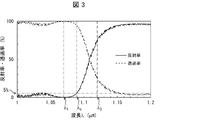
- FIG. 3 is a graph showing reflection characteristics and transmission characteristics of the short pass filter 111 provided in the glass block 11.
- the direction parallel to the central axis of the delivery fiber 21 and the central axis of the glass block 11 is defined as the z-axis direction.
- An arbitrary direction among the orthogonal directions is defined as an x-axis direction, and a direction orthogonal to each of the x-axis and the z-axis is defined as a y-axis direction.
- the direction from the incident surface 11i of the glass block 11 to the exit surface 11o is defined as the z-axis positive direction, and the right-handed orthogonal coordinate system is configured together with the z-axis positive direction.
- the z-axis positive direction is also referred to as the forward direction
- the z-axis negative direction is also referred to as the reverse direction. This is because in the fiber laser system FLS (see FIG. 5) described in the second embodiment, the output laser light propagates along the positive z-axis direction.
- the output head 1 includes a glass block 11, a delivery fiber 21, a glass tube 31, and an outer cylinder 41.
- a clad mode stripper 22 is provided at an intermediate portion of the delivery fiber 21.
- the output head 1 has an optical fiber termination structure that terminates an output side end of the optical fiber.
- the output side end of the output delivery fiber ODF provided in each of the fiber laser system FLS and the fiber laser apparatus FLA is provided.
- Each of the output head 1 and the delivery fiber 21 shown in FIG. 1A includes an output head OH and an output delivery fiber ODF provided in each of the fiber laser system FLS and the fiber laser apparatus FLA shown in FIG.
- the glass block 11 is made of glass having a high transmittance in a wavelength region including the wavelength ⁇ 1 of the output laser light (that is, having a low absorption rate) and a high melting point. Further, the glass material constituting the glass block 11 may have a high transmittance even in a wavelength region including the wavelength ⁇ 2 of Stokes light that can be generated as the output laser light having high intensity propagates through the delivery fiber 21. preferable.
- 1.07 ⁇ m is adopted as the wavelength ⁇ 1 .
- the wavelength ⁇ 2 is 1.12 ⁇ m.
- the material constituting the glass block 11 is preferably quartz (also called quartz).
- the shape of the glass block 11 is a cylinder as shown in FIGS.
- the glass block 11 has a diameter of 9 mm and an axial length of 20 mm.
- one bottom surface is defined as an incident surface 11i and the other bottom surface is defined as 11o.
- the incident surface 11i is located on the z-axis negative direction side
- the exit surface 11o is located on the z-axis positive direction side.
- the shape of the glass block 11 is not limited to a column,
- the shape (columnar shape) which looks like a cylinder may be sufficient as a macro, a prism may be sufficient, (( A truncated cone may be used as shown in a). That is, the shape of the glass block 11 may be any shape as long as it is columnar.
- each FS propagates in the forward direction in the glass block 11 while expanding at a predetermined angle.
- output surface 11o is configured to exceed the reflectance reflectance with respect to the output laser beam L FO for the Stokes light L FS.
- a short pass filter 111 having a reflectivity with respect to the Stokes light L FS higher than a reflectivity with respect to the output laser light L FO is laminated on the emission surface 11o.
- the short pass filter 111 corresponds to the layered filter described in the claims.
- the short pass filter 111 is referred to as SPF 111.
- the short pass filter is a filter that transmits light having a shorter wavelength than a predetermined wavelength (for example, a cutoff wavelength ⁇ c ) and reflects light having a longer wavelength than the predetermined wavelength among filters called edge filters. It is.
- the SPF 111 preferably has reflection characteristics (wavelength dependence of reflectance) and transmission characteristics (wavelength dependence of transmittance) as shown in FIG.
- the absorption rate of the SPF 111 can be regarded as zero, the sum of the reflectance and the transmittance is 1.
- the SPF 111 is configured by laminating a plurality of dielectric films. That is, the SPF 111 is composed of a dielectric multilayer film. By controlling the dielectric constant and film thickness of each dielectric film, a short pass filter having desired reflection characteristics can be designed.
- SPF111 is a reflectance for the Stokes light L FS 10% or more, and a reflectance for the output laser beam L FO is 2% or less.
- the cut-off wavelength ⁇ c of the SPF 111 is preferably located between the wavelength ⁇ 1 and the wavelength ⁇ 2 .
- the cutoff wavelength ⁇ c means a wavelength at which the reflectance of the SPF 111 is 5%.
- the cut-off wavelength ⁇ c of the SPF 111 shown in FIG. 3 is approximately 1.09 ⁇ m. SPF111 has an edge reflectance in the wavelength region of the longer wavelength side in the wavelength range near the cutoff wavelength lambda c is increased sharply.
- the SPF 111 having the reflection characteristics shown in FIG. 3 has a reflectance corresponding to the wavelength ⁇ 1 of 0.1% and a reflectance for the wavelength ⁇ 2 of 72.1%. Therefore, the SPF 111 transmits (1) almost all of the output laser light L FO as it is, (2) 72.1% of the Stokes light L FS is reflected as the return Stokes light L RS , and (3) the Stokes light L FS. 27.9% of the light is transmitted as Stokes light LFS ′ .
- the output laser beam LFO is provided to suppress reflection in the reverse direction on the exit surface of the glass block or the surface of the output coupler, and is a so-called anti-reflection (AR) film. It is. AR film reduces the reflectance to light included in a wide wavelength range, for increasing the transmittance, the output laser beam L FO and Stokes light L FS Tonouchi Stokes light L FS selectively be reflected more strongly Can not.
- the diameter of the spot S RS of the return Stokes light L RS on the incident surface 11i is twice the diameter of the spot of the Stokes light L FS on the output surface 11o. For example, if the spot diameter of the Stokes light L FS in the exit surface 11o (spot diameter) is 1.7 mm, the spot S RS diameter (spot diameter) it becomes 3.4 mm.
- the delivery fiber 21 is a double clad fiber including a core 211, an inner clad 212, and an outer clad 213.
- a multimode fiber is used as the delivery fiber 21.
- the core 211, the inner cladding 212, and the outer cladding 213 are all made of quartz.
- the exit surface 21o which is one end surface of the delivery fiber 21 is fused in a state of being abutted against the entrance surface 11i. That is, the entrance surface 11i and the exit surface 21o are optically coupled.
- coupling when the term “coupling” is used without particular notice, it means “optical coupling”.
- a removal section I in which the outer cladding 213 is removed is provided in the middle portion of the delivery fiber 21.
- a cladding mode stripper 22 is provided in the removal section I.
- the intermediate portion of the delivery fiber 21 means a portion excluding both ends of the delivery fiber 21.
- the removal section I may be provided in any portion as long as it is a portion excluding both ends of the delivery fiber 21. However, the removal section I is preferably provided in the vicinity of the exit surface 21o in terms of removing the return Stokes light L RS (see FIG. 1B) described later at an early stage.
- the cladding mode stripper 22 includes a high refractive index resin body 221 that covers the inner cladding 212 in the removal section I, and a reinforcing member 222 that supports the high refractive index resin body 221. Yes.
- the reinforcing member 222 is a rectangular parallelepiped block having a V-shaped groove formed on the upper surface.
- the reinforcing member 222 is made of an opaque material such as alumina.
- Alumina is suitable as a material for the reinforcing member 222 because it has good thermal conductivity, a low coefficient of linear expansion, and good workability.
- the high refractive index resin body 221 is obtained by curing a resin having a high refractive index injected into the V-shaped groove of the reinforcing member 222, for example.
- the high refractive index resin body 221 is made of a translucent resin having a refractive index equal to or higher than the refractive index of the inner cladding 212 of the delivery fiber 21 in the removal section I.
- the clad mode stripper 22 configured in this manner removes light (for example, Stokes light L FS and return Stokes light L RS ) coupled to the inner cladding 212 and the outer cladding 213 from the modes propagating through the delivery fiber 21. can do.
- light for example, Stokes light L FS and return Stokes light L RS
- the clad mode stripper 22 is adopted as an example of the clad mode stripper.
- the clad mode stripper provided in the output head 1 is not limited to the clad mode stripper 22 and may be any clad mode stripper.
- the glass tube 31 is a columnar glass member, and is made of quartz in the present embodiment.
- the glass tube 31 is provided in a section of the delivery fiber 21 from the emission surface 21 o of the delivery fiber 21 to the cladding mode stripper 22. In this section, the inner wall surface of the glass tube 31 is in contact with the surface of the delivery fiber 21 (the surface of the outer cladding 213) and covers the surface of the delivery fiber 21.
- the glass tube 31 is fixed by shrink fitting to the delivery fiber 21.
- the glass tube 31 before being fixed to the delivery fiber 21 is configured such that its inner diameter exceeds the outer diameter of the delivery fiber 21.
- Glass tube 31, when it is shrink-fitted against the delivery fiber 21, (1) is heated to a temperature above the glass transition point T g of the own and heated to a temperature above (2)
- Glass transition point T g remain, passed through a delivery fiber 21 on the inside of its cylinder, (3) with respect to its outer surface 313, it is under pressure, is cooled to a temperature below (4) a glass transition temperature T g.
- the glass tube 31 and the delivery fiber 21 are fixed in a state where the inner wall of the glass tube 31 is in close contact with the surface of the delivery fiber 21.
- the glass tube 31 is coupled to the glass block 11 via an end surface 311 which is one end surface thereof. More specifically, the end surface 311 is fused to the entrance surface 11i together with the exit surface 21o. Further, as shown in FIG. 2A, the glass tube 31 is coupled to the high refractive index resin body 221 of the cladding mode stripper 22 through an end surface 312 which is the other end surface.
- the high refractive index resin body 221 will be described later.
- the outer diameter of the glass tube 31 is preferably greater than the spot diameter of the spot S RS. Moreover, it is preferable that the end surface 311 is couple
- the outer surface 313 of the glass tube 31 has a concavo-convex structure that scatters at least Stokes light among the output laser light LFO and Stokes light. That is, it is preferable that the outer surface 313 is roughened into a ground glass shape.
- the Stokes light referred to here includes both the Stokes light LFS and the return Stokes light LRS .
- the outer cylinder 41 is a cylindrical glass member that houses the glass block 11, the delivery fiber 21, and the glass tube 31, and functions as a casing of the output head 1. To do.
- the outer cylinder 41 is made of quartz.
- the reinforcing member 222 of the cladding mode stripper 22 is illustrated as floating in the air inside the outer cylinder 41.
- FIG. 2B the actual reinforcing member 222 is fixed in a state where the two vertices 2221 and 2222 (see FIG. 2B) located on the negative side in the y-axis direction are in contact with the inner wall 411 of the outer cylinder 41.
- the load applied to the fusion point where the emission surface 21o of the delivery fiber 21 and the end surface 311 of the glass tube 31 and the incident surface 11i of the glass block 11 are fused can be greatly reduced.
- the glass block 11 outputs the laser beam L FO supplied from the delivery fiber 21 (the laser beam described in the claims). ) From the exit surface 11o.
- the reflectance with respect to the Stokes light L FS corresponding to the output laser beam L FO is configured to exceed the reflectivity for outputting the laser beam L FO.
- the output laser beam L FO and Stokes light L FS incident on the incident surface 11i propagates the inside of the glass block 11 while spreading at a predetermined angle determined by the numerical aperture of the delivery fiber 21, output surface 11o is reached.
- the exit surface 11o the reflectance with respect to the Stokes light L FS is configured to exceed the reflectivity for outputting the laser beam L FO. Therefore, among the emission output laser beam reaches the surface 11o L FO and Stokes light L FS, Stokes light L FS is reflected more strongly than the output laser beam L FO at the exit surface 11o a return Stokes beam L RS.
- Part of the return Stokes beam L RS is after propagated to the incident surface 11i from the exit surface 11o, it can bind to the core 211.
- the return Stokes beam L RS Stokes light coupled to the core of the delivery fiber that the (Stokes light propagating in the core 211 in other words in the opposite direction, not shown in FIG. 1 (b)) This is referred to as first return Stokes light.
- first return Stokes light because many of the return Stokes beam L RS, dissipated without binding to the core 211 of the delivery fiber 21. Therefore, even if the exit surface 11o is constructed so that the reflectance for the Stokes light L FS exceeds the reflectivity for outputting the laser beam L FO, the intensity of the first return Stokes light becomes extremely low .
- the Stokes light L FS is reflected more strongly than the output laser light L FO on the exit surface 11o of the glass block among the output laser light L FO and the Stokes light L FS . Therefore, compared with the conventional glass block, the glass block 11 can suppress the intensity
- the output laser beam L FO and the Stokes beam L FS ′ are focused by a spatial optical system (not shown in FIG. 5) and then the workpiece W, which is a workpiece, is processed. Irradiate the surface.
- the Stokes light LFS ′ irradiated on the surface of the workpiece W is reflected on the surface of the workpiece W.
- a part of the Stokes light LFS ′ reflected on the surface of the workpiece W can be refocused by the spatial optical system and can be coupled to the core 211 after propagating from the exit surface 11o to the entrance surface 11i.
- the Stokes light LFS ′ caused by the Stokes light coupled to the core 211 is a second. This is called return Stokes light.
- the intensity of the second return Stokes beam is proportional to the reflectance for the Stokes light L FS 'of the surface of the workpiece, and is proportional to the square of the transmittance for the Stokes light L FS of the exit surface 11o. Therefore, lowering the transmittance for the Stokes light L FS emission surface 11o, in other words, to increase the reflectance for the Stokes light L FS of the exit surface 11o is to reduce the intensity of the second return Stokes beam means. Therefore, compared with the case where the conventional glass block is used, the intensity of the second return Stokes light when the glass block 11 is used is clearly reduced.
- the glass block 11 can reduce the intensity of the second return Stokes light without substantially increasing the intensity of the first return Stokes light. Therefore, the glass block 11 can reduce the sum of the intensity of the first return Stokes light and the intensity of the second return Stokes light as compared with the conventional glass block, and thus Stokes oscillation occurs. The possibility can be reduced.
- the present glass block can be made compact as compared with the case where the demultiplexing element is provided separately.
- the present glass block can provide a more compact glass block while reducing the possibility of occurrence of Stokes oscillation.
- the glass block 11 has a secondary effect that it is maintenance-free.
- the laser head shown in FIG. 1 of Patent Document 3 includes a spatial optical system including a demultiplexing element.
- the glass block 11 does not include a spatial optical system.
- the glass block 11 is configured such that the exit surface 11o, which is one end surface of the columnar glass block 11, satisfies the above-described predetermined condition. Since the emission surface 11o cannot move, the glass block 11 is maintenance-free.
- an SPF 111 (a layered filter described in claims) having a reflectivity with respect to the Stokes light L FS higher than a reflectivity with respect to the output laser light L FO is laminated on the emission surface 11o.
- SPF111 is a reflectance for the Stokes light L FS 10% or more, reflectance to output the laser beam L FO is 2% or less, it is preferable.
- the cutoff wavelength ⁇ c of the SPF 111 is located between the wavelength ⁇ 1 corresponding to the output laser light L FO and the wavelength ⁇ 2 corresponding to the Stokes light L FS .
- the Stokes beam L FS ′ that passes through the emission surface 11o and reaches the workpiece is reliably suppressed. can do.
- (1) is reflected or scattered in the work
- (2) by passing through the forward and reverse path, you are possible to reliably suppress the intensity of the return Stokes beam L RS to again bind the delivery fiber 21. That is, the possibility of occurrence of Stokes oscillation can be reliably reduced.
- the output head 1 (the optical fiber termination structure described in the claims) includes a glass block 11 and a delivery fiber 21 in which an exit surface 21o is optically coupled to an entrance surface 11i.
- the output head 1 configured as described above has the same effect as the glass block 11.
- the delivery fiber 21 includes a clad mode stripper 22 provided at an intermediate portion thereof.
- the output head 1 can further reduce the possibility that Stokes oscillation will occur.
- the delivery fiber 21 includes the clad mode stripper 22, the demultiplexing element and unnecessary light included in the laser head shown in FIG. 1 of Patent Document 3 (replaced by the output head 1 of the present specification). There is no need to provide a propagation optical fiber and an unnecessary light processing unit. Therefore, the output head 1 can be made more compact than the laser head shown in FIG.
- a cylindrical glass tube 31 provided in a section from the emission surface 21 o of the delivery fiber 21 to the cladding mode stripper 22 and covering the surface of the outer cladding 213 of the delivery fiber 21.
- the glass tube 31 is coupled to the glass block 11 through an end surface 311 that is one end surface thereof, and is coupled to the cladding mode stripper 22 through an end surface 312 that is the other end surface. preferable.
- the return Stokes light L RS coupled to the glass tube 31 (at least a part of the return Stokes light L RS not coupled to the delivery fiber 21 again) propagates through the glass tube 31 in the reverse direction and reaches the cladding mode stripper 22. Finally, it is removed by the cladding mode stripper 22. Therefore, the output head 1 can be reliably remove at least a portion of not again coupled to the delivery fiber 21 return Stokes beam L RS.
- the outer diameter of the glass tube 31 is above the spot diameter of reaching the entrance surface 11i after reflected by the exit surface 11o return Stokes beam L RS (diameter of the spot S RS), the end surface 311 of the glass tube 31 is
- the glass block 11 is preferably bonded so as to include the spot SRS .
- the glass tube 31 is reflected at the exit surface 11o, binds to most again did not bind return Stokes beam L RS to the delivery fiber 21 (all ideally). Therefore, the output head 1, most of the newly unbound return Stokes beam L RS to the delivery fiber 21 (ideally all) can be reliably removed.
- the outer surface 313 of the glass tube 31 has an uneven structure that scatters at least Stokes light among the output laser light LFO and Stokes light (Stokes light LFS and return Stokes light LRS ). preferable.
- At least a part of the return Stokes light L RS coupled to the glass tube 31 can be dissipated to the outside of the glass tube 31.
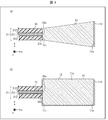
- FIGS. 4A and 4B are a cross-sectional view of a first modification and a cross-sectional view of a second modification of the glass block shown in FIG. 1, respectively.
- the glass block 11 of the first modification is obtained by reducing the diameter of the incident surface 11i of the glass block.
- the diameter of the incident surface 11 i is equal to the outer diameter of the glass tube 31.
- the entrance surface 11i and the exit surface 11o are arranged so as to be concentric.
- the glass block 11 of the first modification is configured such that the area of the incident surface 11i is less than the area of the exit surface 11o.
- the glass block 11 of the first modification has a truncated cone shape with the incident surface 11i as the upper bottom surface and the emission surface 11o as the lower bottom surface.
- the volume in the vicinity of the incident surface of the glass block 11 of the first modification can be reduced. Therefore, since the heat capacity in the vicinity of the incident surface of the glass block 11 can be reduced, the fusion can be easily performed when the fusion is adopted as a method for joining the glass block 11 and the delivery fiber 21. .
- the glass block 11 of the second modified example combines the outer surface 11s of the surfaces of the glass block 11 and the end surface 311 of the glass tube 31 of the incident surface 11i.
- the metal film 12 is further provided in a region excluding the region where the region is formed.
- the region where the end surface 311 is coupled includes the region where the emission surface 21 o of the delivery fiber 21 is coupled. Therefore, the metal film 12 is not formed in the region where the emission surface 21o is coupled.
- the region where the exit surface 21o is coupled is rephrased as the region where the exit surface 21o is scheduled to be coupled.
- the metal film 12 is laminated on the entire surface of the glass block 11 except for the region where the short pass filter 111 is laminated and the region where the end surface 311 of the glass tube 31 is bonded. ing. Therefore, the Stokes light L RS can be prevented from leaking outside the glass block 11. Therefore, it is possible to heat caused by the Stokes light L RS is reduce or eliminate the possibility of influencing the outside (ie, the output head 1) of the glass block 11.
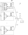
- FIG. 5 is a configuration diagram of the fiber laser system FLS.
- the fiber laser system FLS includes an output head OH (that is, the output head 1 shown in FIG. 1A) according to an embodiment of the present invention.
- the fiber laser system FLS is a laser device for processing a workpiece W that is a processing target.
- n fiber laser units FLU1 to FLUn, n laser delivery fibers LDF1 to LDFn, An output combiner OC, an output delivery fiber ODF, and an output head OH are provided.
- the fiber laser units FLU1 to FLUn and the laser delivery fibers LDF1 to LDFn correspond one to one.
- n is an arbitrary natural number of 1 or more, and represents the number of fiber laser units FLU1 to FLUn and laser delivery fibers LDF1 to LDFn.
- the output combiner OC is an aspect of the multiplexing unit described in the claims, and includes n input ports and one output port.
- the output combiner OC combines n laser beams input to each input port into one laser beam, and outputs the combined laser beam from the output port.
- Each of the output delivery fiber ODF and the output head OH of the fiber laser system FLS corresponds to the delivery fiber 21 and the output head 1 shown in FIG.
- the fiber laser unit FLUI (i is a natural number between 1 and n) generates laser light.
- forward-pumped fiber lasers are used as the fiber laser units FLU1 to FLUn.
- the fiber laser unit FLUi is connected to the input end of the corresponding laser delivery fiber LDFi.
- the laser beam generated by the fiber laser unit FLUi is input to the laser delivery fiber LDFi.
- the laser delivery fiber LDFi guides the laser light generated by the corresponding fiber laser unit FLUi.
- the laser delivery fibers LDF1 to LDFn may be single mode fibers or fu mode fibers having 10 or less modes.
- the fu mode fiber is used as the laser delivery fibers LDF1 to LDFn.
- the output end of the laser delivery fiber LDFi is connected to the input port of the output combiner OC.
- the laser light generated by the fiber laser unit FLUi and guided through the laser delivery fiber LDFi is input to the output combiner OC through this input port.
- the output combiner OC is generated by each of the fiber laser units FLU1 to FLUn, and combines the laser beams guided by the laser delivery fibers LDF1 to LDFn.
- the output port of the output combiner OC is connected to the input end of the output delivery fiber ODF.
- the laser beam combined by the output combiner OC is input to the output delivery fiber ODF. That is, the incident surface of the output delivery fiber ODF is coupled to a plurality of fiber laser units FLUi via the output combiner OC.
- the output delivery fiber ODF guides the laser beam combined by the output combiner OC.
- a multimode fiber is used as the output delivery fiber ODF.
- the output end of the output delivery fiber ODF is connected to the output head OH.
- a spatial optical system for example, a convex lens, not shown in FIG. 5 for focusing the laser beam emitted from the output head OH on the surface of the work W is provided between the output head OH and the work W. ing.
- the laser beam combined by the output combiner OC is emitted from the output head OH, and is irradiated onto the workpiece W in a state of being focused by the spatial optical system.
- the output combiner OC is adopted as an example of the multiplexing unit described in the claims.
- a spatial optical system including a plurality of convex lenses can be employed as an example of the combining unit recited in the claims.
- this spatial optical system is composed of n convex lenses, each convex lens focuses the laser beam emitted from the laser delivery fiber LDFi of each fiber laser unit FLUi and outputs each focused laser beam. What is necessary is just to be arrange
- the configuration of the fiber laser unit FLU1 provided in the fiber laser system FLS will be described with reference to FIG.
- the fiber laser units FLU2 to FLUn are configured in the same manner as the fiber laser unit FLU1.
- the fiber laser unit FLU1 is a forward pumping type fiber laser, and as shown in FIG. 5, m pumping light sources PS1 to PSm, m pumping delivery fibers PDF1 to PDFm, pumping combiner PC, and high reflection fiber Bragg A grating FBG-HR, an amplification fiber AF, and a low reflection fiber Bragg grating FBG-LR are provided. That is, the fiber laser unit FLU1 is a resonator type fiber laser unit.
- the excitation light sources PS1 to PSm and the excitation delivery fibers PDF1 to PDFm correspond one to one.
- m is an arbitrary natural number of 2 or more, and represents the number of excitation light sources PS1 to PSm and excitation delivery fibers PDF1 to PDFm.
- the excitation light source PSj (j is a natural number between 1 and m) generates excitation light.
- laser diodes are used as the excitation light sources PS1 to PSm.
- the excitation light source PSj is connected to the input end of the corresponding excitation delivery fiber PDFj. Excitation light generated by the excitation light source PSj is input to the excitation delivery fiber PDFi.
- the excitation delivery fiber PDFj guides the excitation light generated by the corresponding excitation light source PSj.
- the output end of the excitation delivery fiber PDFj is connected to the input port of the excitation combiner PC.
- the excitation light generated by the excitation light source PSj and guided through the excitation delivery fiber PDFj is input to the excitation combiner PC via this input port.
- the excitation combiner PC multiplexes the excitation light generated by each of the excitation light sources PS1 to PSm and guided through each of the excitation delivery fibers PDF1 to PDFm.
- the output port of the excitation combiner PC is connected to the input end of the amplification fiber AF via the high reflection fiber Bragg grating FBG-HR.
- the excitation light transmitted through the highly reflective fiber Bragg grating FBG-HR is input to the amplification fiber AF.
- the amplification fiber AF generates laser light using the excitation light that has passed through the highly reflective fiber Bragg grating FBG-HR.
- the excitation light transmitted through the highly reflective fiber Bragg grating FBG-HR is used to maintain this rare earth element in an inverted distribution state.
- the output end of the amplification fiber AF is connected to the input end of the laser delivery fiber LDF1 via the low reflection fiber Bragg grating FBG-LR.
- the high reflection fiber Bragg grating FBG-HR functions as a mirror at a certain wavelength ⁇ (for example, 1060 nm) (reflectance becomes 99%, for example), and the low reflection fiber Bragg grating FBG-LR serves as a half mirror at the wavelength ⁇ . Function (reflectance becomes 10%, for example).
- the amplification fiber AF together with the high reflection fiber Bragg grating FBG-HR and the low reflection fiber Bragg grating FBG-LR, constitutes a resonator that oscillates laser light of wavelength ⁇ .
- the laser light transmitted through the low reflection fiber Bragg grating FBG-LR is input to the laser delivery fiber LDF1.
- forward-pumped fiber lasers are used as the fiber laser units FLU1 to FLUn, but the present invention is not limited to this. That is, in the present invention, backward pumping type fiber lasers can be used as the fiber laser units FLU1 to FLUn, and bidirectional pumping fiber lasers can be used as the fiber laser units FLU1 to FLUn.
- the fiber laser system FLS configured in this manner has the same effects as the glass block 11 and the output head 1 described in the first embodiment.
- the fiber laser system FLS employs a resonator type fiber laser unit as each of the fiber laser units FLU1 to FLUn which are laser units described in the claims.
- the fiber laser system FLS can adopt a MOPA type fiber laser unit as each of the fiber laser units FLU1 to FLUn.
- the MOPA type fiber laser unit includes a main oscillation (Master Oscillator: MO) unit and a power amplification (Power Amplifier: PA) unit arranged at a subsequent stage of the MO unit.
- the MO unit generates seed light
- the PA unit generates laser light by amplifying the power of the seed light.
- the MO unit may be a resonator type fiber laser unit, or any one of a semiconductor laser unit, a solid state laser unit, a liquid laser unit, and a gas laser unit. Also good.
- the fiber laser system LFS may employ any one of a semiconductor laser unit, a solid-state laser unit, a liquid laser unit, and a gas laser unit as the laser unit described in the claims.
- FIG. 6 is a configuration diagram of the fiber laser apparatus FLA.
- the fiber laser apparatus FLA includes a fiber laser unit FLU1 and an output head OH (that is, the output head 1 shown in FIG. 1A) according to an embodiment of the present invention.
- the fiber laser unit FLU1 provided in the fiber laser apparatus FLA has the same configuration as the fiber laser unit FLU1 provided in the fiber laser system FLS (see FIG. 5). Therefore, in this embodiment, the description of the fiber laser unit FLU1 is omitted.
- the fiber laser apparatus FLA does not need to multiplex laser beams generated by each of the plurality of fiber laser units FLU1 to FLUn. Therefore, the fiber laser apparatus FLA can omit the output combiner OC included in the fiber laser system FLS. As a result, in the fiber laser apparatus FLA, the incident end face of the output delivery fiber ODF is coupled to the fiber laser unit FLU1. As in the case of the fiber laser system FLS, the fiber laser apparatus FLA may employ a resonator type fiber laser unit or a MOPA type fiber laser unit as the fiber laser unit FLU1. Good.
- the MO unit may be a resonator type fiber laser unit, a semiconductor laser unit, a solid state laser unit, a liquid Either a laser unit or a gas laser unit may be used.
- the fiber laser apparatus FLA may employ any one of a semiconductor laser unit, a solid-state laser unit, a liquid laser unit, and a gas laser unit as the laser unit described in the claims.
- the fiber laser apparatus FLA configured as described above has the same effects as the glass block 11 described in the first embodiment, the output head 1, and the fiber laser apparatus FLA described in the second embodiment. .
- the incident end face of the output delivery fiber ODF included in the output head 1 is connected to at least one of the fiber laser units FLU1 to FLUn via the output combiner OC.
- the fiber laser units FLU1 can be coupled to one fiber laser unit FLU1.
- the glass block (11) has an exit surface (21o) of a delivery fiber (21) with respect to the entrance surface (11i), with both bottom surfaces as an entrance surface (11i) and an exit surface (11o). ) Are optically coupled to each other, a columnar glass block (11) for emitting laser light supplied from the delivery fiber (21) from the emission surface (11o), the emission surface (11o) being The reflectance with respect to the Stokes light corresponding to the laser light is higher than the reflectance with respect to the laser light.
- the output surface of a glass block is comprised so that the reflectance with respect to Stokes light may exceed the reflectance with respect to a laser beam. Therefore, of the laser light and Stokes light that has reached the exit surface of the glass block, the Stokes light is reflected more strongly than the laser light on the exit surface of the glass block.
- a portion of the Stokes light reflected by the exit surface of the glass block can be coupled to the core of the delivery fiber after propagating from the exit surface of the glass block to the entrance surface.
- Stokes light (in other words, Stokes light propagating in the reverse direction through the delivery fiber) coupled to the core of the delivery fiber due to the Stokes light reflected on the exit surface of the glass block is referred to as the first return Stokes. Called light.
- the intensity of the first return Stokes light is extremely low.
- the Stokes light is reflected more strongly than the laser light on the exit surface of the glass block. Therefore, the intensity of the Stokes light emitted from the exit surface of the main glass block is suppressed compared to a glass block whose exit surface is configured such that the reflectivity for Stokes light is equal to or less than the reflectivity for laser light. ing.
- a part of the Stokes light emitted from the exit surface of the glass block is reflected on the surface of the workpiece and can be coupled to the core of the delivery fiber after propagating from the exit surface of the glass block to the entrance surface.
- the Stokes light coupled to the core of the delivery fiber due to the Stokes light emitted from the exit surface of the glass block is referred to as the second return Stokes. Called light.
- the second return Stokes the Stokes light coupled to the core of the delivery fiber due to the Stokes light emitted from the exit surface of the glass block
- the second return Stokes the Stokes light propagating in the reverse direction through the delivery fiber
- the intensity of the second return Stokes light is proportional to the reflectance with respect to the Stokes light on the surface of the workpiece, and is proportional to the square of the transmittance with respect to the Stokes light on the exit surface of the glass block. Therefore, reducing the transmittance of the exit surface of the glass block with respect to the Stokes light, in other words, increasing the reflectivity of the exit surface with respect to the Stokes light means that the intensity of the second return Stokes light is reduced. .
- the present glass block can reduce the intensity of the second return Stokes light without substantially increasing the intensity of the first return Stokes light as compared with the conventional glass block. Therefore, since the present glass block can reduce the sum of the intensity of the first return Stokes light and the intensity of the second return Stokes light as compared with the conventional glass block, Stokes oscillation occurs. The possibility can be reduced.
- the present glass block can be made compact as compared with the case where the demultiplexing element is provided separately.
- the present glass block can provide a more compact glass block while reducing the possibility of occurrence of Stokes oscillation.
- this glass block has a secondary effect of being maintenance-free.
- the laser head shown in FIG. 1 of Patent Document 3 includes a spatial optical system including a demultiplexing element.
- the present glass block does not include a spatial optical system.
- the present glass block is configured such that the emission end face, which is one end face of the columnar glass block, satisfies the above-described predetermined condition. Since one end surface of the columnar glass block cannot move, the glass block is maintenance-free.
- a layered filter (111) having a reflectance with respect to the Stokes light that exceeds the reflectance with respect to the laser light is stacked on the emission surface (11o). Is preferable.
- the possibility of occurrence of Stokes oscillation can be reduced without increasing the volume of the glass block.
- the layered filter (111) has a reflectance with respect to the Stokes light of 10% or more and a reflectance with respect to the laser light of 2% or less. It is preferable.
- the cutoff wavelength of the layered filter (111) is located between a wavelength corresponding to the laser light and a wavelength corresponding to the Stokes light. It is preferable.
- the reflection coefficient or the cut-off wavelength for laser light and Stokes light as described above, Stokes light that passes through the exit surface of the glass block and reaches the workpiece can be reliably suppressed. Therefore, (1) the intensity of the Stokes light that is reflected or scattered by the workpiece and (2) rejoins with the delivery fiber can be reliably suppressed by passing through the path opposite to the forward path. That is, the possibility of occurrence of Stokes oscillation can be reliably reduced.
- the cut-off wavelength means a wavelength at which the reflection coefficient is 5%.
- the area of the incident surface (11i) is configured to be smaller than the area of the emission surface (11o).
- the volume in the vicinity of the incident surface of the glass block can be reduced. Therefore, since the heat capacity in the vicinity of the incident surface of the glass block can be reduced, the fusion can be easily performed when the fusion is adopted as a method for coupling the glass block and the delivery fiber.
- the said metal film (12) is laminated on at least a part of the surface excluding the region where the emission surface (21o) of the delivery fiber (21) is planned to be coupled.
- An optical fiber termination structure (1) includes an exit surface with respect to the glass block (11) according to any one aspect described above and the incident surface (11i) of the glass block (11). (21o) and an optically coupled delivery fiber (21).
- the Stokes light is Stokes light generated as the laser light propagates through the delivery fiber (21).
- this optical fiber termination structure has an effect similar to the glass block which concerns on each aspect mentioned above.
- the delivery fiber (21) includes a clad mode stripper (22) provided at an intermediate portion thereof.
- Stokes light also referred to as clad mode
- this optical fiber termination structure can further reduce the possibility of occurrence of Stokes oscillation.
- the delivery fiber includes the cladding mode stripper, the demultiplexing element and unnecessary light included in the laser head shown in FIG. 1 of Patent Document 3 (which can be read as the output head 1 described in claims).
- the optical fiber termination structure can be made more compact than the laser head described in FIG.
- An optical fiber termination structure (1) is provided in a section from the emission surface (21o) of the delivery fiber (21) to the cladding mode stripper (22).
- 21) is further provided with a cylindrical glass tube (31) that covers the surface of the clad (213) provided in the glass block (31) via the one end surface (311) of the glass block (11).
- a glass tube couple
- Stokes light coupled to the glass tube propagates in the reverse direction through the glass tube, reaches the cladding mode stripper, and is finally removed by the cladding mode stripper. . Therefore, this optical fiber termination structure can reliably remove at least a part of the Stokes light that has not been coupled to the delivery fiber.
- the glass tube (31) has an outer diameter reflected by the emission surface (11o) of the glass block (11) and then the glass.
- the spot diameter of the Stokes light that has reached the entrance surface (11i) of the block (11) exceeds the one end surface (311) of the glass tube (31), and the exit surface (11o) of the glass block (11). It is preferable that the glass block (11) is optically coupled so as to include the spot of the Stokes light that has reached.
- the glass tube is reflected on the exit surface of the glass block and is coupled with most of the Stokes light that has not been coupled to the delivery fiber again. Therefore, the present optical fiber termination structure can reliably remove most of the Stokes light that has not been re-coupled to the delivery fiber.
- the outer surface (313) of the glass tube (31) has at least unevenness that scatters the Stokes light among the laser light and the Stokes light. It is preferable that a structure is formed.
- part of the Stokes light propagating in the reverse direction coupled to the glass tube can be dissipated to the outside of the glass tube.
- a laser apparatus (FLA) includes a laser apparatus (FLU1) that emits laser light and the optical fiber termination structure (OH) according to any one aspect described above ( FLA), the incident surface of the delivery fiber (ODF) is optically coupled to the laser unit (FLU1), and the glass block (11) is emitted from the laser unit (FLU1).
- the laser beam supplied from the delivery fiber (ODF) is emitted from the emission surface (11o) of the glass block (11).
- a laser system (FLS) includes one or more laser units (FLU1 to FLUn) each emitting laser light, and each of the one or more laser units (FLU1 to FLUn) emitting light.
- a fiber laser system (FLS) comprising a multiplexing unit (OC) for combining the laser beams into one and the optical fiber termination structure (OH) according to any one of the above-described aspects,
- An incident surface of a fiber (ODF) is optically coupled to the multiplexing unit (OC), and the glass block (11) emits from each of the one or a plurality of laser units (FLU1 to FLUn).
- the laser beam combined by the multiplexing unit (OC) and supplied from the delivery fiber (ODF) is emitted from the glass block (11). Emitted from the surface (11o), and wherein the.
- each of the present laser device and the present laser system has the same effect as the glass block according to each aspect described above.
- the laser unit (FLU1) is a fiber laser unit including a plurality of excitation light sources (PS1 to PSm) and an amplification fiber (AF). It is preferable.
- each of the one or more laser units includes a plurality of excitation light sources (PS1 to PSm) and an amplification fiber (AF).
- PS1 to PSm excitation light sources
- AF amplification fiber
- the multiplexing unit (OC) is preferably a combiner including one or more input ports and one output port.
- One embodiment of the present invention is suitable for a laser apparatus or a laser system that employs a fiber laser unit as a laser unit as described above.
Landscapes
- Physics & Mathematics (AREA)
- Electromagnetism (AREA)
- Optics & Photonics (AREA)
- Engineering & Computer Science (AREA)
- Plasma & Fusion (AREA)
- General Physics & Mathematics (AREA)
- Lasers (AREA)
- Optical Couplings Of Light Guides (AREA)
Abstract
ストークス発振が発生する可能性を低減しつつ、よりコンパクトなガラスブロックを提供する。ガラスブロック(11)は、入射面(11i)に対してデリバリファイバ(21)の出射面(21i)を結合した場合に、レーザ光を出射面(11o)から出射する柱状のガラスブロックである。ガラスブロック(11)の出射面(11o)は、ストークス光に対する反射率がレーザ光に対する反射率を上回るように構成されている。
Description
本発明は、デリバリファイバを光学的に結合可能なガラスブロック、そのようなガラスブロックとデリバリファイバとを備えた光ファイバ終端構造、及びそのような光ファイバ終端構造を備えたファイバレーザシステムに関する。
加工用のレーザ装置として、複数のファイバレーザユニットを備えたファイバレーザシステムが用いられている。このようなファイバレーザシステムにおいて、各ファイバレーザユニットによって生成され、各ファイバレーザユニットのレーザデリバリファイバを伝搬するレーザ光は、出力コンバイナにおいて1つの出力レーザ光に合波され、出力デリバリファイバの入射面に結合される。出力デリバリファイバの出射面には、ガラスブロック(例えば、特許文献1の図3に記載のガラスロッド63や、特許文献2の図3に記載のコアレスファイバなど)の入射面が光学的に結合されている。出力デリバリファイバを伝搬した出力レーザ光は、ガラスブロックの出射面から出射され、該出射面とワークとの間に介在する光学系により集光されたのちにワークに照射される。
特許文献1には、ガラスブロックの出射面に誘電体多層膜を設けることによって、該出射面において出力レーザ光の反射率を低減する技術が記載されている。
また、特許文献2には、出力カプラの表面に、レーザ光の一部を反射し、残りを透過するような特性を有する誘電体多層膜を設ける技術が記載されている。
上述したようなファイバレーザシステムが備えているファイバレーザユニットの数と、各ファイバレーザユニットの定格出力とは、様々である。その一例としては、7個のファイバレーザユニットを備えており、各ファイバレーザユニットの定格出力が1kWであるファイバレーザシステムが挙げられる。すなわち、このファイバレーザシステムの定格出力は、7kWである。
このように高出力なファイバレーザシステムにおいては、その高い出力に起因して、各デリバリファイバ及び出力デリバリファイバの媒質において生じる誘導ラマン散乱、ならびに誘導ラマン散乱に起因するストークス発振が問題となる。各デリバリファイバ及び出力デリバリファイバの何れかにおいて閾値を超える誘導ラマン散乱が生じた場合、ストークス発振が生じる。その結果、各ファイバレーザユニットの出力、すなわちファイバレーザシステムの出力が不安定になり、ワークの加工を続けることができなくなる。また、場合によっては、ストークス発振に起因してファイバレーザシステムが故障することもある。このようなストークス発振は、出力デリバリファイバ及び各デリバリファイバを逆方向(ガラスブロックからファイバレーザユニットへ向かう方向)へ伝搬するストークス光を低減することによって、その発生の確率を低減することができる。
特許文献3の図1には、出力デリバリファイバの終端構造に設けられたレーザヘッドの内部に、不要光とラマン光とを分波する分波素子を配置したファイバレーザ装置が記載されている。ファイバレーザ装置、不要光、及びラマン光の各々は、それぞれ、本願明細書におけるファイバレーザシステム、出力レーザ光、及びストークス光と読み替えられる。分波素子を透過したストークス光は、ワークに照射され、分波素子により反射された不要光は、不要光伝搬用光ファイバによりレーザヘッドの外部へ導かれ、不要光処理部に結合される。不要光処理部は、不要光を熱に変換したうえで、その熱を拡散させることによって不要光を処理する。なお、特許文献3に記載された分波素子は、ラマン光を透過し、不要光を反射するバンドパスフィルタである。なお、特許文献3に記載のレーザヘッドは、本願明細書の出力ヘッドに読み替えられる。
しかし、特許文献3の図1に記載のファイバレーザ装置では、レーザヘッド(本願明細書における光ファイバ終端構造)の内部に分波素子を別個に設け、不要光伝搬用ファイバを用いて不要光をレーザヘッドの外部へ導く必要があった。したがって、このレーザヘッドには、更なるコンパクト化を図る余地がある。レーザヘッドは、ワークの近傍に配置される。加工時の自由度を高めるために、レーザヘッドをできるだけコンパクトにしたいとの要望がある。
本発明の一態様は、上述した課題に鑑みなされたものであり、その目的は、ストークス発振が発生する可能性を低減しつつ、よりコンパクトなガラスブロック、光ファイバ終端構造、レーザ装置、及びレーザシステムを提供することである。
上記の課題を解決するために、本発明の一態様に係るガラスブロックは、その両底面を入射面及び出射面として、前記入射面に対してデリバリファイバの出射面を光学的に結合した場合に、前記デリバリファイバから供給されたレーザ光を前記出射面から出射する柱状のガラスブロックであって、前記出射面は、前記レーザ光に対応するストークス光に対する反射率が前記レーザ光に対する反射率を上回る、ことを特徴とする。
本発明の一態様によれば、ストークス発振が発生する可能性を低減しつつ、よりコンパクトなガラスブロック、光ファイバ終端構造、レーザ装置、及びレーザシステムを提供することができる。
〔第1の実施形態〕
本発明の一実施形態に係るガラスブロック11について、図1~図3を参照して説明する。図1の(a)は、本実施形態に係るガラスブロック11を備えた出力ヘッド1の断面図である。図1の(b)は、ガラスブロック11の拡大断面図である。図1の(c)は、ガラスブロック11をデリバリファイバ21の側(z軸負方向側)からみた矢視図である。図2の(a)は、デリバリファイバ21が備えているクラッドモードストリッパ22の縦断面図である。図2の(b)は、クラッドモードストリッパ22の横断面図である。図3は、ガラスブロック11が備えているショートパスフィルタ111の反射特性及び透過特性を示すグラフである。
本発明の一実施形態に係るガラスブロック11について、図1~図3を参照して説明する。図1の(a)は、本実施形態に係るガラスブロック11を備えた出力ヘッド1の断面図である。図1の(b)は、ガラスブロック11の拡大断面図である。図1の(c)は、ガラスブロック11をデリバリファイバ21の側(z軸負方向側)からみた矢視図である。図2の(a)は、デリバリファイバ21が備えているクラッドモードストリッパ22の縦断面図である。図2の(b)は、クラッドモードストリッパ22の横断面図である。図3は、ガラスブロック11が備えているショートパスフィルタ111の反射特性及び透過特性を示すグラフである。
図1の(a)~(c)に図示した座標系は、デリバリファイバ21の中心軸及びガラスブロック11の中心軸に平行な方向(すなわち軸方向)をz軸方向と定め、z軸方向に直交する方向(すなわち径方向)のうち任意の方向をx軸方向と定め、x軸及びz軸の各々に直交する方向をy軸方向と定めている。また、ガラスブロック11の入射面11iから出射面11oへ向かう方向をz軸正方向とし、z軸正方向とともに右手系の直交座標系を構成するように、x軸正方向及びy軸正方向の各々を定めている。なお、入射面11i及び出射面11oについては、後述する。以下では、z軸正方向のことを順方向とも呼び、z軸負方向のことを逆方向とも呼ぶ。第2の実施形態において説明するファイバレーザシステムFLS(図5参照)において、出力レーザ光は、z軸正方向に添って伝搬するためである。
(ガラスブロック11)
図1の(a)に示すように、出力ヘッド1は、ガラスブロック11と、デリバリファイバ21と、ガラス管31と、外筒41とを備えている。デリバリファイバ21の中間部には、クラッドモードストリッパ22が設けられている。
図1の(a)に示すように、出力ヘッド1は、ガラスブロック11と、デリバリファイバ21と、ガラス管31と、外筒41とを備えている。デリバリファイバ21の中間部には、クラッドモードストリッパ22が設けられている。
出力ヘッド1は、光ファイバの出射側の端部を終端する光ファイバ終端構造であり、例えば、ファイバレーザシステムFLS及びファイバレーザ装置FLAの各々が備えている出力デリバリファイバODFの出射側の端部を終端するために利用可能である。図1の(a)に示した出力ヘッド1及びデリバリファイバ21の各々は、それぞれ、図5に示したファイバレーザシステムFLS及びファイバレーザ装置FLAの各々が備えている出力ヘッドOH及び出力デリバリファイバODFに対応する。
ガラスブロック11は、出力レーザ光の波長λ1を含む波長域において高い透過率を有し(すなわち低い吸収率を有し)、且つ、高い融点を有するガラスにより構成されている。また、ガラスブロック11を構成するガラス材料は、強度が高い出力レーザ光がデリバリファイバ21を伝搬することに伴い生じ得るストークス光の波長λ2を含む波長域においても、高い透過率を有することが好ましい。本実施形態においては、波長λ1として、1.07μmを採用する。その場合、波長λ2は、1.12μmである。波長λ1=1.07μmであり、波長λ2=1.12μmである場合、ガラスブロック11を構成する材料としては、石英(クオーツとも呼ばれる)が好適である。
ガラスブロック11の形状は、図1の(a)~(c)に示すように円柱である。本実施形態において、ガラスブロック11の直径は、9mmであり、その軸方向の長さは、20mmである。ガラスブロック11の両底面のうち一方の底面を入射面11iとし、他方の底面を11oとする。入射面11iは、z軸負方向側に位置し、出射面11oは、z軸正方向側に位置する。なお、ガラスブロック11の形状は、円柱に限定されるものではなく、マクロには円柱に見える形状(円柱状の形状)であってもよいし、角柱であってもよいし、図4の(a)に示すように円錐台であってもよい。すなわち、ガラスブロック11の形状は、柱状であれば如何なる形状であってもよい。
図1の(b)に示すように、入射面11iに対してデリバリファイバ21の出射面21oが結合されている場合、デリバリファイバ21を順方向に伝搬してきた出力レーザ光LFO及びストークス光LFSの各々は、所定の角度で拡がりながらガラスブロック11の内部を順方向に伝搬する。
ガラスブロック11において、出射面11oは、ストークス光LFSに対する反射率が出力レーザ光LFOに対する反射率を上回るように構成されている。具体的には、出射面11oには、ストークス光LFSに対する反射率が出力レーザ光LFOに対する反射率を上回るショートパスフィルタ111が積層されている。ショートパスフィルタ111は、請求の範囲に記載の層状フィルタに対応する。また、以下において、ショートパスフィルタ111のことをSPF111と記載する。ショートパスフィルタは、エッジフィルタと呼ばれるフィルタのうち、所定の波長(例えばカットオフ波長λc)よりも短波長側の光を透過し、該所定の波長よりも長波長側の光を反射するフィルタである。
SPF111は、図3に示すような反射特性(反射率の波長依存性)及び透過特性(透過率の波長依存性)を有することが好ましい。SPF111の吸収率をゼロとみなせる場合、反射率と透過率との和は、1になる。
SPF111は、複数の誘電体膜を積層することによって構成されている。すなわち、SPF111は、誘電体多層膜によって構成されている。各誘電体膜の誘電率及び膜厚を制御することによって、所望の反射特性を有するショートパスフィルタを設計することができる。
図3に示すように、SPF111は、ストークス光LFSに対する反射率が10%以上であり、出力レーザ光LFOに対する反射率が2%以下であることが好ましい。
また、図3に示すように、SPF111のカットオフ波長λcは、波長λ1と、波長λ2との間に位置することが好ましい。なお、本願明細書において、カットオフ波長λcは、SPF111の反射率が5%となる波長を意味する。図3に示したSPF111のカットオフ波長λcは、およそ1.09μmである。SPF111は、カットオフ波長λc近傍の波長域のうち長波長側の波長域に反射率が急激に増大するエッジを有する。
図3に示した反射特性を有するSPF111は、波長λ1に対応する反射率が0.1%であり、波長λ2に対する反射率が72.1%である。したがって、SPF111は、(1)出力レーザ光LFOのほぼ全てをそのまま透過し、(2)ストークス光LFSの72.1%を戻りストークス光LRSとして反射し、(3)ストークス光LFSの27.9%をストークス光LFS’として透過する。
特許文献1に記載されたガラスブロックの出射面に設けられた誘電体多層膜、及び、特許文献2に記載された出力カプラの表面に設けられた誘電体多層膜は、いずれも順方向に伝搬する出力レーザ光LFOがガラスブロックの出射面あるいは出力カプラの表面において逆方向へ向けて反射されることを抑制するために設けられたものであり、いわゆる反射防止(AR:Anti-reflection)膜である。AR膜は、幅広い波長域に含まれる光に反射率を低減し、透過率を高めるため、出力レーザ光LFOとストークス光LFSとのうちストークス光LFSを選択的により強く反射することはできない。
ストークス光LFSは、所定の角度で拡がりながら順方向に伝搬するので、戻りストークス光LRSは、前記所定の角度で拡がりながら逆方向に伝搬する。したがって、入射面11iにおける戻りストークス光LRSのスポットSRS(図1の(c)参照)の直径は、出射面11oにおけるストークス光LFSのスポットの直径の2倍となる。例えば、出射面11oにおけるストークス光LFSのスポットの直径(スポット径)が1.7mmである場合、スポットSRSの直径(スポット径)は、3.4mmとなる。
(デリバリファイバ21)
図1の(b)に示すように、デリバリファイバ21は、コア211と、内側クラッド212と、外側クラッド213とを備えたダブルクラッドファイバである。また、本実施形態においては、デリバリファイバ21としてマルチモードファイバを採用している。コア211、内側クラッド212、及び外側クラッド213は、何れも、石英製である。
図1の(b)に示すように、デリバリファイバ21は、コア211と、内側クラッド212と、外側クラッド213とを備えたダブルクラッドファイバである。また、本実施形態においては、デリバリファイバ21としてマルチモードファイバを採用している。コア211、内側クラッド212、及び外側クラッド213は、何れも、石英製である。
デリバリファイバ21の一方の端面である出射面21oは、入射面11iに突き当てられた状態で融着されている。すなわち、入射面11iと出射面21oとは、光学的に結合している。なお、以下において、特に断りなく「結合」との用語を用いた場合、それは、「光学的な結合」を意味する。
図2の(a)に示すように、デリバリファイバ21の中間部には、外側クラッド213を除去した除去区間Iが設けられている。除去区間Iには、クラッドモードストリッパ22が設けられている。デリバリファイバ21の中間部は、デリバリファイバ21の両端部を除いた部分を意味する。
除去区間Iは、デリバリファイバ21の両端部を除いた部分であれば何れの部分に設けられていてもよい。ただし、後述する戻りストークス光LRS(図1の(b)参照)を早い段階で除去するという点では、除去区間Iは、出射面21oの近傍に設けられていることが好ましい。
図2の(a)に示すように、クラッドモードストリッパ22は、除去区間Iにおいて内側クラッド212を覆う高屈折率樹脂体221、及び、高屈折率樹脂体221を支持する補強部材222を備えている。
図2の(b)に示すように、補強部材222は、上面にV字溝が形成された直方体状のブロックである。この補強部材222は、不透明材料、例えば、アルミナにより構成されている。アルミナは、熱伝導性が良く、線膨張係数が小さく、加工性が良いため、補強部材222の材料として好適である。
高屈折率樹脂体221は、例えば、補強部材222のV字溝に注入された高い屈折リスを有する樹脂を硬化させたものである。この高屈折率樹脂体221は、除去区間Iにおけるデリバリファイバ21の内側クラッド212の屈折率以上の屈折率を有する透光性樹脂により構成されている。
このように構成されたクラッドモードストリッパ22は、デリバリファイバ21を伝搬するモードのうち、内側クラッド212及び外側クラッド213に結合している光(例えばストークス光LFS及び戻りストークス光LRS)を除去することができる。
なお、本実施形態では、クラッドモードストリッパの一例としてクラッドモードストリッパ22を採用している。しかし、出力ヘッド1が備えているクラッドモードストリッパは、クラッドモードストリッパ22に限定されるものではなく、如何なるクラッドモードストリッパであってもよい。
(ガラス管31)
図1の(a)~(c)に示すように、ガラス管31は、円柱状ガラス部材であり、本実施形態においては石英製である。ガラス管31は、デリバリファイバ21のうち、デリバリファイバ21の出射面21oからクラッドモードストリッパ22までの区間に設けられている。ガラス管31は、該区間において、その内壁面がデリバリファイバ21の表面(外側クラッド213の表面)に接し、且つ、デリバリファイバ21の前記表面を覆っている。
図1の(a)~(c)に示すように、ガラス管31は、円柱状ガラス部材であり、本実施形態においては石英製である。ガラス管31は、デリバリファイバ21のうち、デリバリファイバ21の出射面21oからクラッドモードストリッパ22までの区間に設けられている。ガラス管31は、該区間において、その内壁面がデリバリファイバ21の表面(外側クラッド213の表面)に接し、且つ、デリバリファイバ21の前記表面を覆っている。
本実施形態において、ガラス管31は、デリバリファイバ21に対して焼き嵌めすることによって固定されている。具体的には、デリバリファイバ21に固定される前のガラス管31は、その内径がデリバリファイバ21の外径を上回るように構成されている。ガラス管31は、デリバリファイバ21に対して焼き嵌めされるときに、(1)自身のガラス転移点Tgを超える温度まで加熱され、(2)ガラス転移点Tgを超える温度まで加熱された状態のまま、自身の筒の内側にデリバリファイバ21を通され、(3)自身の外側面313に対して、圧力を加えられ、(4)ガラス転移点Tgを下回る温度まで冷却される。以上の工程により、ガラス管31の内壁がデリバリファイバ21の表面に密着した状態で、ガラス管31とデリバリファイバ21とは固定される。
図1の(b)に示すように、ガラス管31は、その一方の端面である端面311を介してガラスブロック11と結合している。より具体的には、端面311は、出射面21oとともに入射面11iに融着されている。また、図2の(a)に示すように、ガラス管31は、その他方の端面である端面312を介してクラッドモードストリッパ22の高屈折率樹脂体221と結合している。高屈折率樹脂体221については、後述する。
図1の(c)に示すように、ガラス管31の外径は、スポットSRSのスポット径を上回ることが好ましい。また、端面311は、スポットSRSを包含した状態で、ガラスブロック11に結合されていることが好ましい。
また、ガラス管31の外側面313には、出力レーザ光LFO及びストークス光のうち少なくともストークス光を散乱する凹凸構造が形成されていることが好ましい。すなわち、外側面313は、その表面がすりガラス状に荒らされていることが好ましい。なお、ここでいうストークス光は、ストークス光LFS及び戻りストークス光LRSの双方を含む。
(外筒41)
図1の(a)に示すように、外筒41は、ガラスブロック11と、デリバリファイバ21と、ガラス管31とを収容する円筒形のガラス部材であって、出力ヘッド1の筐体として機能する。本実施形態において、外筒41は、石英製である。
図1の(a)に示すように、外筒41は、ガラスブロック11と、デリバリファイバ21と、ガラス管31とを収容する円筒形のガラス部材であって、出力ヘッド1の筐体として機能する。本実施形態において、外筒41は、石英製である。
図1の(a)において、クラッドモードストリッパ22の補強部材222は、外筒41の内部において宙に浮いているように図示されている。しかし、実際の補強部材222は、y軸方向負方向側に位置する2つの頂点2221,2222(図2の(b)参照)が外筒41の内壁411に接した状態で固定されている。この構成によれば、デリバリファイバ21の出射面21o及びガラス管31の端面311と、ガラスブロック11の入射面11iとを融着した融着点に掛かる負荷を大幅に低減することができる。
(まとめ)
以上のように、ガラスブロック11は、入射面11iに対してデリバリファイバ21の出射面21oを結合した場合に、デリバリファイバ21から供給された出力レーザ光LFO(請求の範囲に記載のレーザ光)を出射面11oから出射する柱状のガラスブロックである。出射面11oは、出力レーザ光LFOに対応するストークス光LFSに対する反射率が出力レーザ光LFOに対する反射率を上回るように構成されている。
以上のように、ガラスブロック11は、入射面11iに対してデリバリファイバ21の出射面21oを結合した場合に、デリバリファイバ21から供給された出力レーザ光LFO(請求の範囲に記載のレーザ光)を出射面11oから出射する柱状のガラスブロックである。出射面11oは、出力レーザ光LFOに対応するストークス光LFSに対する反射率が出力レーザ光LFOに対する反射率を上回るように構成されている。
出射面21oから出射され、入射面11iに入射した出力レーザ光LFO及びストークス光LFSは、デリバリファイバ21の開口数により定まる所定の角度で拡がりながらガラスブロック11の内部を伝搬し、出射面11oに到達する。上述のように、出射面11oは、ストークス光LFSに対する反射率が出力レーザ光LFOに対する反射率を上回るように構成されている。そのため、出射面11oに到達した出力レーザ光LFO及びストークス光LFSのうち、ストークス光LFSは、出射面11oにおいて出力レーザ光LFOよりも強く反射され戻りストークス光LRSとなる。戻りストークス光LRSの一部は、出射面11oから入射面11iへ伝搬したあとに、コア211に結合し得る。以下において、戻りストークス光LRSに起因し、デリバリファイバのコアに結合したストークス光(換言すればコア211を逆方向に伝搬するストークス光、図1の(b)には不図示)のことを第1の戻りストークス光と称す。ただし、戻りストークス光LRSの多くは、デリバリファイバ21のコア211に結合することなく散逸する。したがって、ストークス光LFSに対する反射率が出力レーザ光LFOに対する反射率を上回るように出射面11oが構成されている場合であっても、この第1の戻りストークス光の強度は、極めて低くなる。とはいえ、ストークス光LFSに対する反射率が出力レーザ光LFOに対する反射率を下回るように構成された出射面を有するガラスブロック(以下、従来のガラスブロック)を用いた場合と比較して、ガラスブロック11を用いた場合における第1の戻りストークス光の強度は、わずかに増大する。
また、上述したように、出力レーザ光LFO及びストークス光LFSのうち、ストークス光LFSがガラスブロックの出射面11oにおいて出力レーザ光LFOよりも強く反射されている。そのため、従来のガラスブロックと比較して、ガラスブロック11は、出射面11oを透過しワークに至るストークス光LFS’の強度を抑制することができる。出力レーザ光LFO及びストークス光LFS’は、第2の実施形態において説明するように、空間光学系(図5には不図示)により集束されたのちに、加工対象物であるワークWの表面に照射される。
ワークWの表面に照射されたストークス光LFS’の一部は、ワークWの表面において反射される。ワークWの表面において反射されたストークス光LFS’の一部は、上記空間光学系により再び集束され、且つ、出射面11oから入射面11iへ伝搬したあとに、コア211に結合し得る。以下において、ストークス光LFS’に起因し、コア211に結合したストークス光(換言すればデリバリファイバを逆方向に伝搬するストークス光、図1の(b)には不図示)のことを第2の戻りストークス光と称す。出射面11oにおいて反射された戻りストークス光LRSの場合と異なり、ワークの表面において反射されたストークス光の多くは、そのままコア211に結合する。これは、ワークの表面において反射されたストークス光が上記空間光学系により再び集束されるためである。したがって、ストークス発振が発生する可能性を低減するためには、第2の戻りストークス光の強度を低減することが重要である。
ここで、第2の戻りストークス光の強度は、ワークの表面のストークス光LFS’に対する反射率に比例し、且つ、出射面11oのストークス光LFSに対する透過率の2乗に比例する。したがって、出射面11oのストークス光LFSに対する透過率を下げること、換言すれば、出射面11oのストークス光LFSに対する反射率を高めることは、第2の戻りストークス光の強度を低減することを意味する。そのため、従来のガラスブロックを用いた場合と比較して、ガラスブロック11を用いた場合における第2の戻りストークス光の強度は、明らかに減少する。
以上のように、ガラスブロック11は、第1の戻りストークス光の強度をほとんど増大させることなく第2の戻りストークス光の強度を低減することができる。そのため、ガラスブロック11は、従来のガラスブロックと比較して、第1の戻りストークス光の強度と、第2の戻りストークス光の強度との和を低減することができるため、ストークス発振が発生する可能性を低減することができる。
また、上記の構成によれば、従来のレーザヘッドのように、レーザ光とストークス光とを分波する分波素子を別個に設ける必要がない。そのため、本ガラスブロックは、分波素子を別個に設ける場合と比較して、コンパクト化を図ることができる。
以上のように、本ガラスブロックは、ストークス発振が発生する可能性を低減しつつ、よりコンパクトなガラスブロックを提供することができる。
更に、ガラスブロック11は、メンテナンスフリーであるという副次的な効果を奏する。特許文献3の図1に示したレーザヘッドは、分波素子を含む空間光学系を含む。それに対し、ガラスブロック11は、空間光学系を含まない。特許文献3の図1に示したレーザヘッドにおいては、分波素子の角度を適切に調整する必要があり、定期的にメンテナンスを施すことが求められる。一方、ガラスブロック11は、柱状のガラスブロック11の一方の端面である出射面11oが、上述した所定の条件を満たすように構成されている。出射面11oは、可動し得ないものであるため、ガラスブロック11は、メンテナンスフリーである。
また、出射面11oには、ストークス光LFSに対する反射率が出力レーザ光LFOに対する反射率を上回るSPF111(請求の範囲に記載の層状フィルタ)が積層されている、ことが好ましい。
この構成によれば、ガラスブロック11の体積を増加させることなく、ストークス発振が発生する可能性を低減することができる。
また、SPF111は、ストークス光LFSに対する反射率が10%以上であり、出力レーザ光LFOに対する反射率が2%以下である、ことが好ましい。
また、SPF111のカットオフ波長λcは、出力レーザ光LFOに対応する波長λ1とストークス光LFSに対応する波長λ2との間に位置する、ことが好ましい。
出力レーザ光LFO及びストークス光LFSに対する反射係数、あるいは、カットオフ波長λcを上述したように構成することによって、出射面11oを透過し、ワークに至るストークス光LFS’を確実に抑制することができる。したがって、(1)ワークにおいて反射又は散乱され、(2)往路と逆の経路を通ることによって、デリバリファイバ21と改めて結合する戻りストークス光LRSの強度を確実に抑制することができる。すなわち、ストークス発振が発生する可能性を確実に低減することができる。
出力ヘッド1(請求の範囲に記載の光ファイバ終端構造)は、ガラスブロック11と、入射面11iに対して、出射面21oが光学的に結合されたデリバリファイバ21と、を備えている。
このように構成された出力ヘッド1は、ガラスブロック11と同様の効果を奏する。
また、デリバリファイバ21は、その中間部に設けられたクラッドモードストリッパ22を備えている、ことが好ましい。
この構成によれば、デリバリファイバに改めて結合した戻りストークス光LRSのうち、デリバリファイバ21の内側クラッド212及び外側クラッド213(請求の範囲に記載のクラッド)に結合した戻りストークス光LRSのうちクラッドを伝搬する戻りストークス光LRSを除去することができる。そのため、戻りストークス光LRSを更に抑制することができる。したがって、出力ヘッド1は、ストークス発振が発生する可能性を更に低減することができる。
また、デリバリファイバ21がクラッドモードストリッパ22を備えていることにより、特許文献3の図1に記載のレーザヘッド(本願明細書の出力ヘッド1に読み替えられる)が備えている分波素子、不要光伝搬用光ファイバ、及び不要光処理部を設ける必要がない。したがって、出力ヘッド1は、特許文献3の図1に記載のレーザヘッドと比較して、コンパクト化を図ることができる。
また、デリバリファイバ21の出射面21oからクラッドモードストリッパ22までの区間に設けられ、デリバリファイバ21の外側クラッド213の表面を覆う筒状のガラス管31を更に備えていることが好ましい。ガラス管31は、その一方の端面である端面311を介してガラスブロック11と結合しており、且つ、その他方の端面である端面312を介してクラッドモードストリッパ22と結合している、ことが好ましい。
このように構成されたガラス管31は、戻りストークス光LRSのうち、デリバリファイバ21に改めて結合しなかった戻りストークス光LRSの少なくとも一部と結合する。ガラス管31に結合した戻りストークス光LRS(デリバリファイバ21に改めて結合しなかった戻りストークス光LRSの少なくとも一部)は、ガラス管31を逆方向に伝搬し、クラッドモードストリッパ22に至り、最終的にクラッドモードストリッパ22により除去される。そのため、出力ヘッド1は、デリバリファイバ21に改めて結合しなかった戻りストークス光LRSの少なくとも一部を確実に除去することができる。
また、ガラス管31の外径は、出射面11oで反射されたあとに入射面11iに到達した戻りストークス光LRSのスポット径(スポットSRSの直径)を上回り、ガラス管31の端面311は、スポットSRSを包含するように、ガラスブロック11結合されている、ことが好ましい。
この構成によれば、ガラス管31は、出射面11oにおいて反射され、デリバリファイバ21に改めて結合しなかった戻りストークス光LRSの大部分(理想的には全部)と結合する。そのため、出力ヘッド1は、デリバリファイバ21に改めて結合しなかった戻りストークス光LRSの大部分(理想的には全部)を確実に除去することができる。
また、ガラス管31の外側面313には、出力レーザ光LFO及びストークス光(ストークス光LFS及び戻りストークス光LRS)のうち少なくともストークス光を散乱する凹凸構造が形成されている、ことが好ましい。
この構成によれば、ガラス管31に結合した戻りストークス光LRS少なくともの一部をガラス管31の外部へ散逸させることができる。
〔変形例〕
図1に示したガラスブロック11の第1の変形例及び第2の変形例について、図4を参照して説明する。図4の(a)及び(b)は、それぞれ、図1に示したガラスブロックの第1の変形例の断面図及び第2の変形例の断面図である。
図1に示したガラスブロック11の第1の変形例及び第2の変形例について、図4を参照して説明する。図4の(a)及び(b)は、それぞれ、図1に示したガラスブロックの第1の変形例の断面図及び第2の変形例の断面図である。
図4の(a)に示すように、第1の変形例のガラスブロック11は、ガラスブロックの入射面11iの直径を縮小することによって得られる。第1の変形例のガラスブロック11において、入射面11iの直径は、ガラス管31の外径と等しい。なお、入射面11iと、出射面11oとは、同心円となるように配置されている。
以上のように、第1の変形例のガラスブロック11は、入射面11iの面積が出射面11oの面積を下回るように構成されている。換言すれば、第1の変形例のガラスブロック11は、入射面11iを上底面とし、出射面11oを下底面とする円錐台形状を有する。
この構成によれば、第1の変形例のガラスブロック11の入射面近傍における体積を小さくすることができる。したがって、ガラスブロック11の入射面近傍の熱容量を小さくすることができるので、ガラスブロック11とデリバリファイバ21とを結合する方法として融着を採用する場合に、容易に融着を実施することができる。
また、図4の(b)に示すように、第2の変形例のガラスブロック11は、ガラスブロック11の表面のうち、外側面11sと、入射面11iのうちガラス管31の端面311が結合されている領域を除いた領域に積層された金属膜12を更に備えている。端面311が結合されている領域は、デリバリファイバ21の出射面21oが結合されている領域を包含する。したがって、金属膜12は、出射面21oが結合されている領域には、形成されていない。なお、デリバリファイバ21を結合される前の状態のガラスブロック11において、出射面21oが結合されている領域は、出射面21oが結合されることが予定されている領域と言い換えられる。
この構成によれば、逆方向に伝搬するストークス光LRSがガラスブロック11の外部に漏洩することを抑制することができる。特に本変形例では、ガラスブロック11の表面のうち、ショートパスフィルタ111が積層されている領域と、ガラス管31の端面311が結合されている領域とを除いた全域に金属膜12が積層されている。そのため、ストークス光LRSがガラスブロック11の外部に漏洩することを防止することができる。したがって、ストークス光LRSに起因する熱がガラスブロック11の外部(すなわち出力ヘッド1)に影響を与える可能性を低減又はなくすことができる。
〔第2の実施形態〕
本発明の第2の実施形態に係るファイバレーザシステムFLSについて、図5を参照して説明する。図5は、ファイバレーザシステムFLSの構成図である。ファイバレーザシステムFLSは、本発明の一実施形態に係る出力ヘッドOH(すなわち図1の(a)に示した出力ヘッド1)を備えている。
本発明の第2の実施形態に係るファイバレーザシステムFLSについて、図5を参照して説明する。図5は、ファイバレーザシステムFLSの構成図である。ファイバレーザシステムFLSは、本発明の一実施形態に係る出力ヘッドOH(すなわち図1の(a)に示した出力ヘッド1)を備えている。
ファイバレーザシステムFLSは、加工対象物であるワークWを加工するためのレーザ装置であり、図5に示すように、n個のファイバレーザユニットFLU1~FLUn、n個のレーザデリバリファイバLDF1~LDFn、出力コンバイナOC、出力デリバリファイバODF、及び出力ヘッドOHを備えている。ファイバレーザユニットFLU1~FLUnとレーザデリバリファイバLDF1~LDFnとは、互いに一対一に対応する。ここで、nは、1以上の任意の自然数であり、ファイバレーザユニットFLU1~FLUn及びレーザデリバリファイバLDF1~LDFnの個数を表す。なお、図5においては、n=7の場合のファイバレーザシステムFLSの構成例を示している。また、出力コンバイナOCは、請求の範囲に記載の合波部の一態様であり、n個の入力ポートと1つの出力ポートを備えている。出力コンバイナOCは、各入力ポートに入力されたn個のレーザ光を1つのレーザ光に合波し、合波したレーザ光を出力ポートから出力する。
ファイバレーザシステムFLSの出力デリバリファイバODF及び出力ヘッドOHの各々は、それぞれ、図1に示したデリバリファイバ21及び出力ヘッド1に対応する。
ファイバレーザユニットFLUi(iは1以上n以下の自然数)は、レーザ光を生成する。本実施形態においては、前方励起型のファイバレーザをファイバレーザユニットFLU1~FLUnとして用いている。ファイバレーザユニットFLUiは、対応するレーザデリバリファイバLDFiの入力端に接続されている。ファイバレーザユニットFLUiにて生成されたレーザ光は、このレーザデリバリファイバLDFiに入力される。
レーザデリバリファイバLDFiは、対応するファイバレーザユニットFLUiにて生成されたレーザ光を導波する。レーザデリバリファイバLDF1~LDFnは、シングルモードファイバであってもよいし、モード数が10以下のフューモードファイバであってもよい。
本実施形態においては、フューモードファイバをレーザデリバリファイバLDF1~LDFnとして用いている。レーザデリバリファイバLDFiの出力端は、出力コンバイナOCの入力ポートに接続されている。ファイバレーザユニットFLUiにて生成され、レーザデリバリファイバLDFiを導波されたレーザ光は、この入力ポートを介して出力コンバイナOCに入力される。
出力コンバイナOCは、ファイバレーザユニットFLU1~FLUnの各々にて生成され、レーザデリバリファイバLDF1~LDFnの各々を導波されたレーザ光を合波する。出力コンバイナOCの出力ポートは、出力デリバリファイバODFの入力端に接続されている。出力コンバイナOCにて合波されたレーザ光は、この出力デリバリファイバODFに入力される。すなわち、出力デリバリファイバODFの入射面は、出力コンバイナOCを介して複数のファイバレーザユニットFLUiに結合されている。
出力デリバリファイバODFは、出力コンバイナOCにて合波されたレーザ光を導波する。本実施形態においては、マルチモードファイバを出力デリバリファイバODFとして用いている。出力デリバリファイバODFの出力端は、出力ヘッドOHに接続されている。また、出力ヘッドOHとワークWとの間には、出力ヘッドOHから出射されたレーザ光をワークWの表面において集束するための空間光学系(例えば凸レンズ、図5には不図示)が設けられている。出力コンバイナOCにて合波されたレーザ光は、この出力ヘッドOHから出射され、上記空間光学系により集束された状態でワークWに照射される。
なお、本実施形態では、請求の範囲に記載の合波部の一例として出力コンバイナOCを採用している。しかし、本発明の一態様では、請求の範囲に記載の合波部の一例として、複数の凸レンズを含む空間光学系を採用することもできる。この空間光学系がn個の凸レンズにより構成されている場合、各凸レンズは、各ファイバレーザユニットFLUiのレーザデリバリファイバLDFiから出射されたレーザ光を集束させ、且つ、集束された各レーザ光を出力デリバリファイバODFのコアに結合するように配置されていればよい。
(ファイバレーザユニットの構成)
ファイバレーザシステムFLSが備えるファイバレーザユニットFLU1の構成について、引き続き図5を参照して説明する。なお、ファイバレーザユニットFLU2~FLUnも、ファイバレーザユニットFLU1と同様に構成されている。
ファイバレーザシステムFLSが備えるファイバレーザユニットFLU1の構成について、引き続き図5を参照して説明する。なお、ファイバレーザユニットFLU2~FLUnも、ファイバレーザユニットFLU1と同様に構成されている。
ファイバレーザユニットFLU1は、前方向励起型のファイバレーザであり、図5に示すように、m個の励起光源PS1~PSm、m個の励起デリバリファイバPDF1~PDFm、励起コンバイナPC、高反射ファイバブラッググレーティングFBG-HR、増幅用ファイバAF、及び低反射ファイバブラッググレーティングFBG-LRを備えている。すなわち、ファイバレーザユニットFLU1は、共振器型のファイバレーザユニットである。励起光源PS1~PSmと励起デリバリファイバPDF1~PDFmとは、互いに一対一に対応する。ここで、mは、2以上の任意の自然数であり、励起光源PS1~PSm及び励起デリバリファイバPDF1~PDFmの個数を表す。なお、図5においては、m=6の場合のファイバレーザユニットFLU1の構成例を示している。
励起光源PSj(jは1以上m以下の自然数)は、励起光を生成する。本実施形態においては、レーザダイオードを励起光源PS1~PSmとして用いている。励起光源PSjは、対応する励起デリバリファイバPDFjの入力端に接続されている。励起光源PSjにて生成された励起光は、この励起デリバリファイバPDFiに入力される。
励起デリバリファイバPDFjは、対応する励起光源PSjにて生成された励起光を導波する。励起デリバリファイバPDFjの出力端は、励起コンバイナPCの入力ポートに接続されている。励起光源PSjにて生成され、励起デリバリファイバPDFjを導波された励起光は、この入力ポートを介して励起コンバイナPCに入力される。
励起コンバイナPCは、励起光源PS1~PSmの各々にて生成され、励起デリバリファイバPDF1~PDFmの各々を導波された励起光を合波する。励起コンバイナPCの出力ポートは、高反射ファイバブラッググレーティングFBG-HRを介して増幅用ファイバAFの入力端に接続されている。励起コンバイナPCにて合波された励起光のうち、高反射ファイバブラッググレーティングFBG-HRを透過した励起光は、増幅用ファイバAFに入力される。
増幅用ファイバAFは、高反射ファイバブラッググレーティングFBG-HRを透過した励起光を用いて、レーザ光を生成する。本実施形態においては、コアに希土類元素(例えばYb)が添加されたダブルクラッドファイバ(ラマンゲイン係数=1×10-13[1/W])を増幅用ファイバAFとして用いている。高反射ファイバブラッググレーティングFBG-HRを透過した励起光は、この希土類元素を反転分布状態に維持するために用いられる。増幅用ファイバAFの出力端は、低反射ファイバブラッググレーティングFBG-LRを介してレーザデリバリファイバLDF1の入力端に接続されている。高反射ファイバブラッググレーティングFBG-HRは、ある波長λ(例えば、1060nm)においてミラーとして機能し(反射率が例えば99%となり)、低反射ファイバブラッググレーティングFBG-LRは、その波長λにおいてハーフミラーとして機能する(反射率が例えば10%となる)。このため、増幅用ファイバAFは、高反射ファイバブラッググレーティングFBG-HR及び低反射ファイバブラッググレーティングFBG-LRと共に、波長λのレーザ光を発振する共振器を構成する。増幅用ファイバAFにて生成されたレーザ光のうち、この低反射ファイバブラッググレーティングFBG-LRを透過したレーザ光は、レーザデリバリファイバLDF1に入力される。
なお、本実施形態においては、前方励起型のファイバレーザをファイバレーザユニットFLU1~FLUnとして用いているが、本発明は、これに限定されない。すなわち、本発明においては、後方励起型のファイバレーザをファイバレーザユニットFLU1~FLUnとして用いることもできるし、双方向励起型のファイバレーザをファイバレーザユニットFLU1~FLUnとして用いることもできる。
このように構成されたファイバレーザシステムFLSは、第1の実施形態において説明したガラスブロック11、及び、出力ヘッド1と同様の効果を奏する。
なお、本実施形態において、ファイバレーザシステムFLSは、請求の範囲に記載のレーザユニットである各ファイバレーザユニットFLU1~FLUnとして、共振器型のファイバレーザユニットを採用している。しかし、ファイバレーザシステムFLSは、各ファイバレーザユニットFLU1~FLUnとして、MOPA型のファイバレーザユニットを採用することもできる。MOPA型のファイバレーザユニットは、主発振(Master Oscillator:MO)部と、MO部の後段に配置されたパワー増幅(Power Amplifier:PA)部とを備えている。MO部は、種光を生成し、PA部は、種光のパワーを増幅することによってレーザ光を生成する。なお、MOPA型のファイバレーザユニットにおいて、MO部は、共振器型のファイバレーザユニットであってもよいし、半導体レーザユニット、固体レーザユニット、液体レーザユニット、及び気体レーザユニットの何れかであってもよい。
また、ファイバレーザシステムLFSは、請求の範囲に記載のレーザユニットとして、半導体レーザユニット、固体レーザユニット、液体レーザユニット、及び気体レーザユニットの何れかを採用してもよい。
〔第3の実施形態〕
本発明の第3の実施形態に係るファイバレーザ装置FLAについて、図6を参照して説明する。図6は、ファイバレーザ装置FLAの構成図である。ファイバレーザ装置FLAは、ファイバレーザユニットFLU1と、本発明の一実施形態に係る出力ヘッドOH(すなわち図1の(a)に示した出力ヘッド1)を備えている。
本発明の第3の実施形態に係るファイバレーザ装置FLAについて、図6を参照して説明する。図6は、ファイバレーザ装置FLAの構成図である。ファイバレーザ装置FLAは、ファイバレーザユニットFLU1と、本発明の一実施形態に係る出力ヘッドOH(すなわち図1の(a)に示した出力ヘッド1)を備えている。
図6に示すように、ファイバレーザ装置FLAが備えるファイバレーザユニットFLU1は、ファイバレーザシステムFLS(図5参照)が備えているファイバレーザユニットFLU1と同じ構成を有する。したがって、本実施形態は、ファイバレーザユニットFLU1の説明を省略する。
また、ファイバレーザ装置FLAは、ファイバレーザシステムFLSと異なり、複数のファイバレーザユニットFLU1~FLUnの各々にて生成されたレーザ光を合波する必要がない。したがって、ファイバレーザ装置FLAは、ファイバレーザシステムFLSが備えている出力コンバイナOCを省略することができる。その結果、ファイバレーザ装置FLAにおいて、出力デリバリファイバODFの入射端面は、ファイバレーザユニットFLU1に対して結合されている。なお、ファイバレーザシステムFLSの場合と同様に、ファイバレーザ装置FLAは、ファイバレーザユニットFLU1として、共振器型のファイバレーザユニットを採用してもよいし、MOPA型のファイバレーザユニットを採用してもよい。なお、ファイバレーザ装置FLAがファイバレーザユニットFLU1としてMOPA型のファイバレーザユニットを採用する場合、MO部は、共振器型のファイバレーザユニットであってもよいし、半導体レーザユニット、固体レーザユニット、液体レーザユニット、及び気体レーザユニットの何れかであってもよい。また、ファイバレーザ装置FLAは、請求の範囲に記載のレーザユニットとして、半導体レーザユニット、固体レーザユニット、液体レーザユニット、及び気体レーザユニットの何れかを採用してもよい。
このように構成されたファイバレーザ装置FLAは、第1の実施形態において説明したガラスブロック11、及び、出力ヘッド1、並びに、第2の実施形態において説明したファイバレーザ装置FLAと同様の効果を奏する。
本発明の一態様である出力ヘッド1に含まれる出力デリバリファイバODFの入射端面は、図5に示したように、少なくとも1つのファイバレーザユニットFLU1~FLUnに対して、出力コンバイナOCを介して接続することもできるし、図6に示したように、1つのファイバレーザユニットFLU1に対して結合することもできる。
〔付記事項〕
本発明の一態様に係るガラスブロック(11)は、その両底面を入射面(11i)及び出射面(11o)として、前記入射面(11i)に対してデリバリファイバ(21)の出射面(21o)を光学的に結合した場合に、前記デリバリファイバ(21)から供給されたレーザ光を前記出射面(11o)から出射する柱状のガラスブロック(11)であって、前記出射面(11o)は、前記レーザ光に対応するストークス光に対する反射率が前記レーザ光に対する反射率を上回る、ことを特徴とする。
本発明の一態様に係るガラスブロック(11)は、その両底面を入射面(11i)及び出射面(11o)として、前記入射面(11i)に対してデリバリファイバ(21)の出射面(21o)を光学的に結合した場合に、前記デリバリファイバ(21)から供給されたレーザ光を前記出射面(11o)から出射する柱状のガラスブロック(11)であって、前記出射面(11o)は、前記レーザ光に対応するストークス光に対する反射率が前記レーザ光に対する反射率を上回る、ことを特徴とする。
デリバリファイバの出射面から出射され、ガラスブロックの入射面に入射したレーザ光及びストークス光は、開口数により定まる所定の角度で拡がりながらガラスブロックの内部を伝搬し、ガラスブロックの出射面に到達する。上記の構成によれば、ストークス光に対する反射率がレーザ光に対する反射率を上回るようにガラスブロックの出射面が構成されている。そのため、ガラスブロックの出射面に到達したレーザ光及びストークス光のうち、ストークス光は、ガラスブロックの出射面においてレーザ光よりも強く反射される。ガラスブロックの出射面により反射されたストークス光の一部は、ガラスブロックの出射面から入射面へ伝搬したあとに、デリバリファイバのコアに結合し得る。以下において、ガラスブロックの出射面において反射されたストークス光に起因し、デリバリファイバのコアに結合したストークス光(換言すればデリバリファイバを逆方向に伝搬するストークス光)のことを第1の戻りストークス光と称す。この第1の戻りストークス光の強度は、極めて低い。
また、上述したように、ガラスブロックの出射面に到達したレーザ光及びストークス光のうち、ストークス光がガラスブロックの出射面においてレーザ光よりも強く反射されている。そのため、ストークス光に対する反射率がレーザ光に対する反射率以下となるように出射面が構成されたガラスブロックと比較して、その本ガラスブロックの出射面から出射されたストークス光の強度は、抑制されている。ガラスブロックの出射面から出射されたストークス光の一部は、ワークの表面において反射され、且つ、ガラスブロックの出射面から入射面へ伝搬したあとに、デリバリファイバのコアに結合し得る。以下において、ガラスブロックの出射面から出射されたストークス光に起因し、デリバリファイバのコアに結合したストークス光(換言すればデリバリファイバを逆方向に伝搬するストークス光)のことを第2の戻りストークス光と称す。ガラスブロックの出射面において反射されたストークス光の場合と異なり、ワークの表面において反射されたストークス光の多くは、そのままデリバリファイバのコアに結合する。したがって、ストークス発振が発生する可能性を減少させるためには、第2の戻りストークス光の強度を低減することが重要である。
第2の戻りストークス光の強度は、ワークの表面のストークス光に対する反射率に比例し、また、ガラスブロックの出射面のストークス光に対する透過率の2乗に比例する。したがって、ガラスブロックの出射面のストークス光に対する透過率を下げること、換言すれば、この出射面のストークス光に対する反射率を高めることは、第2の戻りストークス光の強度を低減することを意味する。
以上のように、本ガラスブロックは、従来のガラスブロックと比較して、第1の戻りストークス光の強度をほとんど増大させることなく第2の戻りストークス光の強度を低減することができる。そのため、本ガラスブロックは、従来のガラスブロックと比較して、第1の戻りストークス光の強度と、第2の戻りストークス光の強度との和を低減することができるため、ストークス発振が発生する可能性を低減することができる。
また、上記の構成によれば、従来の出力ヘッドのように、レーザ光とストークス光とを分波する分波素子を別個に設ける必要がない。そのため、本ガラスブロックは、分波素子を別個に設ける場合と比較して、コンパクト化を図ることができる。
以上のように、本ガラスブロックは、ストークス発振が発生する可能性を低減しつつ、よりコンパクトなガラスブロックを提供することができる。
更に、本ガラスブロックは、メンテナンスフリーであるという副次的な効果を奏する。特許文献3の図1に示したレーザヘッドは、分波素子を含む空間光学系を含む。それに対し、本ガラスブロックは、空間光学系を含まない。特許文献3の図1に示したレーザヘッドにおいては、分波素子の角度を適切に調整する必要があり、定期的にメンテナンスを施すことが求められる。一方、本ガラスブロックは、柱状のガラスブロックの一方の端面である出射端面が、上述した所定の条件を満たすように構成されている。柱状のガラスブロックの一方の端面は、可動し得ないものであるため、本ガラスブロックは、メンテナンスフリーである。
また、本発明の一態様に係るガラスブロック(11)において、前記出射面(11o)には、前記ストークス光に対する反射率が前記レーザ光に対する反射率を上回る層状フィルタ(111)が積層されている、ことが好ましい。
上記の構成によれば、ガラスブロックの体積を増加させることなく、ストークス発振が発生する可能性を低減することができる。
また、本発明の一態様に係るガラスブロック(11)において、前記層状フィルタ(111)は、前記ストークス光に対する反射率が10%以上であり、前記レーザ光に対する反射率が2%以下である、ことが好ましい。
また、本発明の一態様に係るガラスブロック(11)において、前記層状フィルタ(111)のカットオフ波長は、前記レーザ光に対応する波長と前記ストークス光に対応する波長との間に位置する、ことが好ましい。
レーザ光及びストークス光に対する反射係数、あるいは、カットオフ波長を上述したように構成することによって、ガラスブロックの出射面を透過し、ワークに至るストークス光を確実に抑制することができる。したがって、(1)ワークにおいて反射又は散乱され、(2)往路と逆の経路を通ることによって、デリバリファイバと改めて結合するストークス光の強度を確実に抑制することができる。すなわち、ストークス発振が発生する可能性を確実に低減することができる。
なお、本願明細書において、カットオフ波長は、反射係数が5%になる波長を意味する。
また、本発明の一態様に係るガラスブロック(11)において、前記入射面(11i)の面積は、前記出射面(11o)の面積を下回るように構成されている、ことが好ましい。
上記の構成によれば、ガラスブロックの入射面近傍における体積を小さくすることができる。したがって、ガラスブロックの入射面近傍の熱容量を小さくすることができるので、ガラスブロックとデリバリファイバとを結合する方法として融着を採用する場合に、容易に融着を実施することができる。
また、本発明の一態様に係るガラスブロック(11)において、該ガラスブロック(11)の表面のうち、(1)前記出射面(11o)と、(2)前記入射面(11i)のうち前記デリバリファイバ(21)の出射面(21o)が結合されることが予定されている領域とを除いた表面の少なくとも一部には、金属膜(12)が積層されている、ことが好ましい。
上記の構成によれば、逆方向に伝搬するストークス光がガラスブロックの外部に漏洩することを抑制することができる。したがって、逆方向に伝搬するストークス光に起因する熱がガラスブロックの外部に影響を与える可能性を低減することができる。
本発明の一態様に係る光ファイバ終端構造(1)は、上述した何れか一態様に係るガラスブロック(11)と、前記ガラスブロック(11)の前記入射面(11i)に対して、出射面(21o)が光学的に結合されたデリバリファイバ(21)と、を備えている。また、前記ストークス光は、前記レーザ光が前記デリバリファイバ(21)を伝搬することに伴い生じるストークス光である。
上記の構成によれば、本光ファイバ終端構造は、上述した各態様に係るガラスブロックと同様の効果を奏する。
また、本発明の一態様に係る光ファイバ終端構造(1)において、前記デリバリファイバ(21)は、その中間部に設けられたクラッドモードストリッパ(22)を備えている、ことが好ましい。
上記の構成によれば、デリバリファイバに改めて結合したストークス光のうち、デリバリファイバのクラッドに結合したストークス光(クラッドモードとも呼ぶ)を除去することができる。そのため、逆方向に向かって伝搬するストークス光を更に抑制することができる。したがって、本光ファイバ終端構造は、ストークス発振が発生する可能性を更に低減することができる。
また、デリバリファイバがクラッドモードストリッパを備えていることにより、特許文献3の図1に記載のレーザヘッド(請求の範囲に記載の出力ヘッド1に読み替えられる)が備えている分波素子、不要光伝搬用光ファイバ、及び不要光処理部を設ける必要がない。したがって、本光ファイバ終端構造は、特許文献3の図1に記載のレーザヘッドと比較して、コンパクト化を図ることができる。
また、本発明の一態様に係る光ファイバ終端構造(1)は、前記デリバリファイバ(21)の前記出射面(21o)から前記クラッドモードストリッパ(22)までの区間に設けられ、該デリバリファイバ(21)が備えているクラッド(213)の表面を覆う筒状のガラス管(31)を更に備え、該ガラス管(31)は、その一方の端面(311)を介して前記ガラスブロック(11)と光学的に結合しており、且つ、その他方の端面(312)を介して前記クラッドモードストリッパ(22)と光学的に結合している、ことが好ましい。
上記の構成によれば、ガラス管は、ガラスブロックの出射面において反射され、ガラスブロックの入射面に至ったストークス光のうち、デリバリファイバに改めて結合しなかったストークス光の少なくとも一部と結合する。ガラス管に結合したストークス光(デリバリファイバに改めて結合しなかったストークス光の少なくとも一部)は、ガラス管を逆方向に伝搬し、クラッドモードストリッパに至り、最終的にクラッドモードストリッパにより除去される。そのため、本光ファイバ終端構造は、デリバリファイバに改めて結合しなかったストークス光の少なくとも一部を確実に除去することができる。
また、本発明の一態様に係る光ファイバ終端構造(1)において、前記ガラス管(31)の外径は、前記ガラスブロック(11)の前記出射面(11o)により反射されたあとに前記ガラスブロック(11)の前記入射面(11i)に到達したストークス光のスポット径を上回り、前記ガラス管(31)の前記一方の端面(311)は、ガラスブロック(11)の出射面(11o)に到達したストークス光のスポットを包含するように、前記ガラスブロック(11)と光学的に結合されている、ことが好ましい。
上記の構成によれば、ガラス管は、ガラスブロックの出射面において反射され、デリバリファイバに改めて結合しなかったストークス光の大部分と結合する。そのため、本光ファイバ終端構造は、デリバリファイバに改めて結合しなかったストークス光の大部分を確実に除去することができる。
また、本発明の一態様に係る光ファイバ終端構造(1)において、前記ガラス管(31)の外側面(313)には、前記レーザ光及び前記ストークス光のうち少なくとも前記ストークス光を散乱する凹凸構造が形成されている、ことが好ましい。
上記の構成によれば、ガラス管に結合した逆方向に伝搬するストークス光の一部をガラス管の外部へ散逸させることができる。
本発明の一態様に係るレーザ装置(FLA)は、レーザ光を出射する1つのレーザユニット(FLU1)と、上述した何れか一態様に係る光ファイバ終端構造(OH)とを備えたレーザ装置(FLA)であって、前記デリバリファイバ(ODF)の入射面が前記レーザユニット(FLU1)に対して光学的に結合されており、前記ガラスブロック(11)は、前記レーザユニット(FLU1)から出射され、前記デリバリファイバ(ODF)から供給された前記レーザ光を該ガラスブロック(11)の前記出射面(11o)から出射する、ことを特徴とする。
本発明の一態様に係るレーザシステム(FLS)は、それぞれがレーザ光を出射する1又は複数のレーザユニット(FLU1~FLUn)と、当該1又は複数のレーザユニット(FLU1~FLUn)の各々が出射した前記レーザ光を1つに合波する合波部(OC)と、上述した何れか一態様に係る光ファイバ終端構造(OH)とを備えたファイバレーザシステム(FLS)であって、前記デリバリファイバ(ODF)の入射面が前記合波部(OC)に対して光学的に結合されており、前記ガラスブロック(11)は、前記1又は複数のレーザユニット(FLU1~FLUn)の各々から出射され、前記合波部(OC)により合波され、前記デリバリファイバ(ODF)から供給された前記レーザ光を、該ガラスブロック(11)の前記出射面(11o)から出射する、ことを特徴とする。
これらの構成によれば、本レーザ装置及び本レーザシステムの各々は、何れも上述した各態様に係るガラスブロックと同様の効果を奏する。
また、本発明の一態様に係るレーザ装置(FLA)において、前記レーザユニット(FLU1)は、複数の励起光源(PS1~PSm)と増幅用ファイバ(AF)とを備えたファイバレーザユニットである、ことが好ましい。
また、本発明の一態様に係るレーザシステム(FLS)において、前記1又は複数のレーザユニット(FLU1~FLUn)の各々は、何れも複数の励起光源(PS1~PSm)と増幅用ファイバ(AF)とを備えたファイバレーザユニット(FLU1~FLUn)であり、前記合波部(OC)は、1又は複数の入力ポートと、1つの出力ポートとを備えたコンバイナである、ことが好ましい。
本発明の一態様は、このようにレーザユニットとしてファイバレーザユニットを採用したレーザ装置又はレーザシステムに好適である。
本発明は上述した各実施形態に限定されるものではなく、請求項に示した範囲で種々の変更が可能であり、異なる実施形態にそれぞれ開示された技術的手段を適宜組み合わせて得られる実施形態についても本発明の技術的範囲に含まれる。
1、OH 出力ヘッド
11 ガラスブロック
11i 入射面
11o 出射面
111 ショートパスフィルタ(層状フィルタ)
12 金属膜
21、ODF デリバリファイバ
21o 出射面
22 クラッドモードストリッパ(CMS)
221 高屈折率樹脂体
222 補強部材
31 ガラス管
311 端面(一方の端面)
312 端面(他方の端面)
41 外筒
FLS ファイバレーザシステム
FLA ファイバレーザ装置
11 ガラスブロック
11i 入射面
11o 出射面
111 ショートパスフィルタ(層状フィルタ)
12 金属膜
21、ODF デリバリファイバ
21o 出射面
22 クラッドモードストリッパ(CMS)
221 高屈折率樹脂体
222 補強部材
31 ガラス管
311 端面(一方の端面)
312 端面(他方の端面)
41 外筒
FLS ファイバレーザシステム
FLA ファイバレーザ装置
Claims (15)
- その両底面を入射面及び出射面として、前記入射面に対してデリバリファイバの出射面を光学的に結合した場合に、前記デリバリファイバから供給されたレーザ光を前記出射面から出射する柱状のガラスブロックであって、
前記出射面は、前記レーザ光に対応するストークス光に対する反射率が前記レーザ光に対する反射率を上回る、
ことを特徴とするガラスブロック。 - 前記出射面には、前記ストークス光に対する反射率が前記レーザ光に対する反射率を上回る層状フィルタが積層されている、
ことを特徴とする請求項1に記載のガラスブロック。 - 前記層状フィルタは、前記ストークス光に対する反射率が10%以上であり、前記レーザ光に対する反射率が2%以下である、
ことを特徴とする請求項2に記載のガラスブロック。 - 前記層状フィルタのカットオフ波長は、前記レーザ光に対応する波長と前記ストークス光に対応する波長との間に位置する、
ことを特徴とする請求項2又は3に記載のガラスブロック。 - 前記入射面の面積は、前記出射面の面積を下回るように構成されている、
ことを特徴とする請求項1~4の何れか1項に記載のガラスブロック。 - 該ガラスブロックの表面のうち、(1)前記出射面と、(2)前記入射面のうち前記デリバリファイバの出射面が結合されることが予定されている領域とを除いた表面の少なくとも一部には、金属膜が積層されている、
ことを特徴とする請求項1~5の何れか1項に記載のガラスブロック。 - 請求項1~6の何れか1項に記載のガラスブロックと、
前記ガラスブロックの前記入射面に対して、出射面が光学的に結合されたデリバリファイバと、を備えており、
前記ストークス光は、前記レーザ光が前記デリバリファイバを伝搬することに伴い生じるストークス光である、
ことを特徴とする光ファイバ終端構造。 - 前記デリバリファイバは、その中間部に設けられたクラッドモードストリッパを備えている、
ことを特徴とする請求項7に記載の光ファイバ終端構造。 - 前記デリバリファイバの前記出射面から前記クラッドモードストリッパまでの区間に設けられ、該デリバリファイバが備えているクラッドの表面を覆う筒状のガラス管を更に備え、
該ガラス管は、その一方の端面を介して前記ガラスブロックと光学的に結合しており、且つ、その他方の端面を介して前記クラッドモードストリッパと光学的に結合している、ことを特徴とする請求項8に記載の光ファイバ終端構造。 - 前記ガラス管の外径は、ガラスブロックの入射面に到達したストークス光のスポット径を上回り、
前記ガラス管の前記一方の端面は、ガラスブロックの出射面に到達したストークス光のスポットを包含するように、前記ガラスブロックと光学的に結合されている、
ことを特徴とする請求項9に記載の光ファイバ終端構造。 - 前記ガラス管の外側面には、前記レーザ光及び前記ストークス光のうち少なくとも前記ストークス光を散乱する凹凸構造が形成されている、
ことを特徴とする請求項9又は10に記載の光ファイバ終端構造。 - レーザ光を出射する1つのレーザユニットと、請求項7~11の何れか1項に記載の光ファイバ終端構造とを備えたレーザ装置であって、
前記デリバリファイバの入射面が前記レーザユニットに対して光学的に結合されており、
前記ガラスブロックは、前記レーザユニットから出射され、前記デリバリファイバから供給された前記レーザ光を該ガラスブロックの前記出射面から出射する、
ことを特徴とするレーザ装置。 - 前記レーザユニットは、複数の励起光源と増幅用ファイバとを備えたファイバレーザユニットである、
ことを特徴とする請求項12に記載のレーザ装置。 - それぞれがレーザ光を出射する1又は複数のレーザユニットと、当該1又は複数のレーザユニットの各々が出射した前記レーザ光を1つに合波する合波部と、請求項7~11の何れか1項に記載の光ファイバ終端構造とを備えたレーザシステムであって、
前記デリバリファイバの入射面が前記合波部に対して光学的に結合されており、
前記ガラスブロックは、前記1又は複数のレーザユニットの各々から出射され、前記合波部により合波され、前記デリバリファイバから供給された前記レーザ光を、該ガラスブロックの前記出射面から出射する、
ことを特徴とするレーザシステム。 - 前記1又は複数のレーザユニットの各々は、何れも複数の励起光源と増幅用ファイバとを備えたファイバレーザユニットであり、
前記合波部は、1又は複数の入力ポートと、1つの出力ポートとを備えたコンバイナである、
ことを特徴とする請求項14に記載のレーザシステム。
Applications Claiming Priority (2)
| Application Number | Priority Date | Filing Date | Title |
|---|---|---|---|
| JP2018-085593 | 2018-04-26 | ||
| JP2018085593A JP6636562B2 (ja) | 2018-04-26 | 2018-04-26 | ガラスブロック、光ファイバ終端構造、レーザ装置、及びレーザシステム |
Publications (1)
| Publication Number | Publication Date |
|---|---|
| WO2019207902A1 true WO2019207902A1 (ja) | 2019-10-31 |
Family
ID=68295239
Family Applications (1)
| Application Number | Title | Priority Date | Filing Date |
|---|---|---|---|
| PCT/JP2019/004627 Ceased WO2019207902A1 (ja) | 2018-04-26 | 2019-02-08 | ガラスブロック、光ファイバ終端構造、レーザ装置、及びレーザシステム |
Country Status (2)
| Country | Link |
|---|---|
| JP (1) | JP6636562B2 (ja) |
| WO (1) | WO2019207902A1 (ja) |
Cited By (1)
| Publication number | Priority date | Publication date | Assignee | Title |
|---|---|---|---|---|
| CN113906288A (zh) * | 2019-12-13 | 2022-01-07 | 在线业务解决方案株式会社 | 圆筒内表面检查装置 |
Citations (8)
| Publication number | Priority date | Publication date | Assignee | Title |
|---|---|---|---|---|
| JPS63265206A (ja) * | 1987-04-23 | 1988-11-01 | Fujitsu Ltd | 光フアイバフイルタ |
| JPH0425804A (ja) * | 1990-05-21 | 1992-01-29 | Nippon Telegr & Teleph Corp <Ntt> | 光学接続構造 |
| JP2002006348A (ja) * | 2000-06-21 | 2002-01-09 | Mitsubishi Electric Corp | 光増幅器 |
| US20100329292A1 (en) * | 2008-01-31 | 2010-12-30 | Nkt Photonics A/S | System, device and method for stabilizing the optical output power of an optical system |
| JP2014513411A (ja) * | 2011-03-01 | 2014-05-29 | オーエフエス ファイテル,エルエルシー | 高次モードファイバを用いる超短パルスのファイバデリバリーのための方法、およびシステム |
| WO2015155994A1 (ja) * | 2014-04-10 | 2015-10-15 | アダマンド株式会社 | 光ファイバアセンブリ及び光結合装置、光ファイバ結合装置 |
| US20170017036A1 (en) * | 2015-07-17 | 2017-01-19 | Spi Lasers Uk Limited | Apparatus for combining optical radiation |
| JP2017085042A (ja) * | 2015-10-30 | 2017-05-18 | 株式会社フジクラ | ファイバレーザシステム |
-
2018
- 2018-04-26 JP JP2018085593A patent/JP6636562B2/ja active Active
-
2019
- 2019-02-08 WO PCT/JP2019/004627 patent/WO2019207902A1/ja not_active Ceased
Patent Citations (8)
| Publication number | Priority date | Publication date | Assignee | Title |
|---|---|---|---|---|
| JPS63265206A (ja) * | 1987-04-23 | 1988-11-01 | Fujitsu Ltd | 光フアイバフイルタ |
| JPH0425804A (ja) * | 1990-05-21 | 1992-01-29 | Nippon Telegr & Teleph Corp <Ntt> | 光学接続構造 |
| JP2002006348A (ja) * | 2000-06-21 | 2002-01-09 | Mitsubishi Electric Corp | 光増幅器 |
| US20100329292A1 (en) * | 2008-01-31 | 2010-12-30 | Nkt Photonics A/S | System, device and method for stabilizing the optical output power of an optical system |
| JP2014513411A (ja) * | 2011-03-01 | 2014-05-29 | オーエフエス ファイテル,エルエルシー | 高次モードファイバを用いる超短パルスのファイバデリバリーのための方法、およびシステム |
| WO2015155994A1 (ja) * | 2014-04-10 | 2015-10-15 | アダマンド株式会社 | 光ファイバアセンブリ及び光結合装置、光ファイバ結合装置 |
| US20170017036A1 (en) * | 2015-07-17 | 2017-01-19 | Spi Lasers Uk Limited | Apparatus for combining optical radiation |
| JP2017085042A (ja) * | 2015-10-30 | 2017-05-18 | 株式会社フジクラ | ファイバレーザシステム |
Cited By (1)
| Publication number | Priority date | Publication date | Assignee | Title |
|---|---|---|---|---|
| CN113906288A (zh) * | 2019-12-13 | 2022-01-07 | 在线业务解决方案株式会社 | 圆筒内表面检查装置 |
Also Published As
| Publication number | Publication date |
|---|---|
| JP2019192834A (ja) | 2019-10-31 |
| JP6636562B2 (ja) | 2020-01-29 |
Similar Documents
| Publication | Publication Date | Title |
|---|---|---|
| JP6140072B2 (ja) | レーザ装置および加工装置 | |
| EP0812039B1 (en) | Fiber light source with multimode fiber coupler | |
| WO2012099116A1 (ja) | ファイバレーザ装置およびレーザ光照射位置の位置決め方法 | |
| JP6356856B1 (ja) | クラッドモード光除去構造及びレーザ装置 | |
| US20060098694A1 (en) | Optical fiber for fiber laser, fiber laser, and laser oscillation method | |
| JP5688565B2 (ja) | ファイバレーザ装置と光増幅方法 | |
| JP2021163814A (ja) | 光ファイバ増幅器および光通信システム | |
| JP7809691B2 (ja) | レーザ装置および加工装置 | |
| JP6357207B2 (ja) | 光ファイバ及びファイバレーザ | |
| US7106928B2 (en) | Coupling high power optical sources to small diameter fibers | |
| JP6423914B1 (ja) | クラッドモードストリッパ | |
| JP6636562B2 (ja) | ガラスブロック、光ファイバ終端構造、レーザ装置、及びレーザシステム | |
| WO2020162057A1 (ja) | 構造体、構造体の製造方法、レーザ装置、及びレーザシステム | |
| JP2007250951A (ja) | ダブルクラッドファイバ及びそれを備えたファイバレーザ | |
| JP7300512B2 (ja) | 光増幅装置 | |
| US7724424B2 (en) | Optical module and optical amplification module | |
| JP4899705B2 (ja) | 光増幅モジュール | |
| WO2006098313A1 (ja) | 光増幅器およびレーザ装置 | |
| WO2020203136A1 (ja) | ファイバレーザ装置 | |
| JP5014640B2 (ja) | マルチモードファイバ、光増幅器及びファイバレーザ | |
| JP2007294534A (ja) | 光学的モジュール | |
| JP5202820B2 (ja) | 光結合器、ファイバレーザ及び光ファイバ増幅器 | |
| JP7189790B2 (ja) | 光ファイバレーザおよび合波型光ファイバレーザ | |
| WO2019172398A1 (ja) | 余剰光除去装置及びファイバレーザ | |
| JP2007123594A (ja) | 光ファイバ型光増幅装置及びこれを用いた光ファイバ型レーザ装置 |
Legal Events
| Date | Code | Title | Description |
|---|---|---|---|
| 121 | Ep: the epo has been informed by wipo that ep was designated in this application |
Ref document number: 19793018 Country of ref document: EP Kind code of ref document: A1 |
|
| NENP | Non-entry into the national phase |
Ref country code: DE |
|
| 122 | Ep: pct application non-entry in european phase |
Ref document number: 19793018 Country of ref document: EP Kind code of ref document: A1 |