WO2019220726A1 - 二輪車用タイヤ - Google Patents
二輪車用タイヤ Download PDFInfo
- Publication number
- WO2019220726A1 WO2019220726A1 PCT/JP2019/006129 JP2019006129W WO2019220726A1 WO 2019220726 A1 WO2019220726 A1 WO 2019220726A1 JP 2019006129 W JP2019006129 W JP 2019006129W WO 2019220726 A1 WO2019220726 A1 WO 2019220726A1
- Authority
- WO
- WIPO (PCT)
- Prior art keywords
- land
- tire
- land portion
- portions
- tread
- Prior art date
- Legal status (The legal status is an assumption and is not a legal conclusion. Google has not performed a legal analysis and makes no representation as to the accuracy of the status listed.)
- Ceased
Links
Images




Classifications
-
- B—PERFORMING OPERATIONS; TRANSPORTING
- B60—VEHICLES IN GENERAL
- B60C—VEHICLE TYRES; TYRE INFLATION; TYRE CHANGING; CONNECTING VALVES TO INFLATABLE ELASTIC BODIES IN GENERAL; DEVICES OR ARRANGEMENTS RELATED TO TYRES
- B60C11/00—Tyre tread bands; Tread patterns; Anti-skid inserts
- B60C11/03—Tread patterns
- B60C11/11—Tread patterns in which the raised area of the pattern consists only of isolated elements, e.g. blocks
-
- B—PERFORMING OPERATIONS; TRANSPORTING
- B60—VEHICLES IN GENERAL
- B60C—VEHICLE TYRES; TYRE INFLATION; TYRE CHANGING; CONNECTING VALVES TO INFLATABLE ELASTIC BODIES IN GENERAL; DEVICES OR ARRANGEMENTS RELATED TO TYRES
- B60C11/00—Tyre tread bands; Tread patterns; Anti-skid inserts
- B60C11/03—Tread patterns
- B60C11/0311—Patterns comprising tread lugs arranged parallel or oblique to the axis of rotation
-
- B—PERFORMING OPERATIONS; TRANSPORTING
- B60—VEHICLES IN GENERAL
- B60C—VEHICLE TYRES; TYRE INFLATION; TYRE CHANGING; CONNECTING VALVES TO INFLATABLE ELASTIC BODIES IN GENERAL; DEVICES OR ARRANGEMENTS RELATED TO TYRES
- B60C11/00—Tyre tread bands; Tread patterns; Anti-skid inserts
- B60C11/03—Tread patterns
- B60C11/13—Tread patterns characterised by the groove cross-section, e.g. for buttressing or preventing stone-trapping
- B60C11/1369—Tie bars for linking block elements and bridging the groove
-
- B—PERFORMING OPERATIONS; TRANSPORTING
- B60—VEHICLES IN GENERAL
- B60C—VEHICLE TYRES; TYRE INFLATION; TYRE CHANGING; CONNECTING VALVES TO INFLATABLE ELASTIC BODIES IN GENERAL; DEVICES OR ARRANGEMENTS RELATED TO TYRES
- B60C11/00—Tyre tread bands; Tread patterns; Anti-skid inserts
- B60C11/03—Tread patterns
- B60C11/13—Tread patterns characterised by the groove cross-section, e.g. for buttressing or preventing stone-trapping
- B60C11/1376—Three dimensional block surfaces departing from the enveloping tread contour
-
- B—PERFORMING OPERATIONS; TRANSPORTING
- B60—VEHICLES IN GENERAL
- B60C—VEHICLE TYRES; TYRE INFLATION; TYRE CHANGING; CONNECTING VALVES TO INFLATABLE ELASTIC BODIES IN GENERAL; DEVICES OR ARRANGEMENTS RELATED TO TYRES
- B60C2200/00—Tyres specially adapted for particular applications
- B60C2200/10—Tyres specially adapted for particular applications for motorcycles, scooters or the like
-
- B—PERFORMING OPERATIONS; TRANSPORTING
- B60—VEHICLES IN GENERAL
- B60C—VEHICLE TYRES; TYRE INFLATION; TYRE CHANGING; CONNECTING VALVES TO INFLATABLE ELASTIC BODIES IN GENERAL; DEVICES OR ARRANGEMENTS RELATED TO TYRES
- B60C2200/00—Tyres specially adapted for particular applications
- B60C2200/14—Tyres specially adapted for particular applications for off-road use
Definitions
- the present invention relates to a motorcycle tire (hereinafter, also simply referred to as “tire”), and more particularly, to a motorcycle tire related to improvement of a block-shaped land portion formed in a tread portion, particularly a motorcycle tire.
- a block pattern in which a plurality of blocks are arranged in a tread portion is adopted for a motorcycle tire for traveling on rough terrain such as sandy land and muddy ground.
- various tread patterns have been proposed.
- Patent Document 1 includes a tread whose outer surface forms a tread surface, and the tread includes a main body and a plurality of blocks that protrude substantially outward in the radial direction from the main body.
- a motorcycle tire for traveling on rough terrain in which one of the above blocks has a protrusion extending in a bar shape on the side surface.
- an object of the present invention is to provide a tire for a motorcycle that further improves the traction performance during traveling.
- the present invention provides a tire for a motorcycle including a tread portion formed in an annular shape, A plurality of land portions are formed in the tread portion, and the plurality of land portions are a center land portion disposed on the tire equator of the tread portion and a middle land disposed on the outer side in the tire width direction of the center land portion. And a shoulder land portion disposed on the outer side in the tire width direction of the middle land portion, and at least a part of the plurality of land portions is positioned at a tire circumferential end of the land portion.
- a step portion is provided at least in part, and the height of the land portion where the step portion is provided to the step portion is h1, from the step portion to the upper surface of the land portion. When the height is h2, h1> h2 is satisfied.
- the step portion is provided at least in the center land portion.
- the ratio h2 / h1 of the height h2 from the step portion to the upper surface of the land portion and the height h1 to the step portion of the land portion where the step portion is provided is The range of 0.13 to 0.32 is preferable.
- FIG. 1 is a partial perspective view showing an example of a motorcycle tire of the present invention.
- FIG. 2 is a partial cross-sectional view taken along line AA in FIG. It is a top view which concerns on the other specific example of the land part which provided the level
- FIG. 6 is a partial sectional view taken along line BB in FIG. 5.
- FIG. 1 shows a partial perspective view of an example of a motorcycle tire of the present invention.
- the motorcycle tire 1 of the present invention includes a tread portion 10 formed in an annular shape, and the tread portion 10 is formed with a tread pattern including a plurality of block-shaped land portions.
- the tread pattern in the illustrated tire is a line-symmetric pattern with the tire equator CL as an axis, and the rotation direction is not specified in this tire.
- the plurality of land portions in the tread portion 10 are disposed on the outer side in the tire width direction of the center land portion 11C and the center land portion 11C disposed on the tire equator CL of the tread portion.
- the middle land portion 11M and the shoulder land portion 11S arranged on the outer side in the tire width direction of the middle land portion 11M are included.
- FIG. 2 is a partial cross-sectional view taken along line AA in FIG.
- the center land portion 11C is positioned at the end of the land portion in the tire circumferential direction.
- Step portions 12a and 12b are provided on at least a part of the corner portions 111a and 111b to be formed, on both sides in the illustrated example.
- the height of the land portion 11C provided with the step portions 12a and 12b to the step portions 12a and 12b is h1
- the height of the land portion 11C from the step portions 12a and 12b is It is important that h1> h2 is satisfied when the height to the upper surface is h2.
- the edge component on the ground contact surface can be increased by providing a stepped portion on at least some of the corner portions located at the tire circumferential direction ends of the land portions. As a result, the traction performance can be improved.
- the stepped portions 12a and 12b may be provided at any one of the center land portion 11C, the middle land portion 11M and the shoulder land portion 11S, or may be provided at any combination of two locations, or provided at all. May be.
- the step portions 12a and 12b are provided at least in the center land portion 11C.
- the step portions 12a and 12b have a height h1 from the land portion 11C where the step portions 12a and 12b are provided to the step portions 12a and 12b, and the top surface of the land portion 11C from the step portions 12a and 12b.
- the height up to h2 is h2
- the stepped portion does not come into contact with the ground during traveling, so that the edge effect cannot be obtained and the traction performance improvement effect cannot be obtained.
- the ratio h2 / h1 between the height h2 and the height h1 is preferably 0.13 or more, more preferably 0.17 or more, It is preferably 0.32 or less, and more preferably 0.27 or less.
- the specific dimension of the step portion can be appropriately determined according to the shape and size of the land portion to be arranged, and is not particularly limited.
- the step portion 12a, 12b to the land portion 11C The height h2 to the upper surface can be in the range of 2 mm to 4 mm. If the height h2 is too small or too large, the effect of providing the stepped portion may not be sufficiently obtained.
- the tire circumferential direction length w1 of the land portion 11C excluding the stepped portions 12a and 12b can be, for example, in a range of 15 mm or more and 20 mm or less, and the tire circumferential direction length of the stepped portions 12a and 12b.
- w2 can be set in a range of 2 mm to 4 mm. If the tire circumferential length w1 is too small, the effect of providing the step portion may not be sufficiently obtained, and if the tire circumferential length w2 is too small, the effect of providing the step portion may not be sufficiently obtained. .
- the stepped portion is not limited to being provided in both of the corner portions 111a and 111b located at the tire circumferential direction end of the land portion 11C, and may be provided in one.
- the tire of the present invention is designated as the rotation direction, and the corner portion What is necessary is just to mount
- the tire of the present invention can specify the rotation direction. Can be used without.
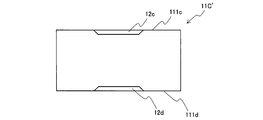
- FIG. 3 is a plan view according to another specific example of a land portion provided with a stepped portion.
- the stepped portion is not limited to the case where it is provided on the entire corners 111 a and 111 b located at the tire circumferential direction end of the land portion 11 ⁇ / b> C.
- Step portions 12c and 12d may be provided as part of the corners 111c and 111d located at the end of the direction, and in this case, the effect of improving the traction performance can be obtained.
- region of the step part in a corner part may differ, and a level
- the arrangement area of each part may be changed, and is not particularly limited.
- FIG. 4 is a plan view according to still another specific example of the land portion provided with the stepped portion.
- the land portion 11C ′′ provided with the stepped portion may be such that the corner portions 111e and 111f located at the tire circumferential direction end are formed in a curved shape. Since the edge components can be increased by providing the step portions 12e and 12f in the portions 111e and 111f, it is possible to contribute to improvement of traction performance.
- the stepped portion is not limited to being provided in a single step as illustrated, and may be formed in two or more steps.
- the height from the land portion where two or more step portions are provided to the lowermost step portion is h1
- the height from the lower step portion to the upper surface of the land portion that is, It is assumed that h1> hn is satisfied, where hn is the total height of two or more stepped portions.
- the stepped portions 12a and 12b are preferably formed so that the even portions 13a and 13b have an R shape. Thereby, generation
- the configuration other than the step portions of the center land portion 11C, the middle land portion 11M, and the shoulder land portion 11S can be determined as appropriate based on the prior art, and is not particularly limited.
- the tread portion 10 in addition to the center land portion 11C, the middle land portion 11M, and the shoulder land portion 11S, the tread portion 10 may have other land portions, and in the case of having other land portions. May be provided with the stepped portion on another land portion.
- the center land portion 11C, the middle land portion 11M, and the shoulder land portion 11S arranged in a plurality in the tire circumferential direction may have different shapes and dimensions.
- the center land portion 11C includes a land portion 111C having a substantially rectangular shape and a land portion 112C having a substantially rectangular shape and having a recess along the tire circumferential direction on the tire equator.
- the middle land portion 11M has a substantially rectangular shape, has a protruding portion similar to the contour line at the center, and has a shape in which sipes are engraved along the contour line of the protruding portion.
- the shoulder land portion 11S has a substantially pentagonal shape, and has a concave portion similar to the contour line in the central portion.
- FIG. 5 shows a partial perspective view of another example of the motorcycle tire of the present invention.
- the two-wheeled vehicle tire 2 shown in the figure includes a tread portion 20 formed in an annular shape, and the tread portion 20 is formed with a tread pattern including a plurality of block-shaped land portions.
- the tread pattern in the illustrated tire is a left-right asymmetric pattern, and the rotation direction is not specified also in this tire.
- a plurality of land portions in the illustrated tread portion 20 include a center land portion 21C disposed on the tire equator CL of the tread portion, a middle land portion 21M disposed on the outer side in the tire width direction of the center land portion 21C, and a middle And a shoulder land portion 21S disposed on the outer side in the tire width direction of the land portion 21M.
- FIG. 6 shows a partial cross-sectional view along the line BB in FIG. Also in the illustrated tire 2, at least a part of the plurality of land portions formed in the tread portion, in the illustrated example, the center land portion 21 ⁇ / b> C, corner portions 211 a and 211 b located at the tire circumferential end of the land portion. Step portions 22a and 22b are provided on at least a part of them, in the illustrated example, on both sides. Further, as shown in the figure, the height of the land portion 21C provided with the step portions 22a and 22b to the step portions 22a and 22b is h1, and the height from the step portions 22a and 22b to the upper surface of the land portion 21C. Where h1> h2 is satisfied.
- the upper surface of the land portion 21 ⁇ / b> C means the upper surface of the land portion 21 ⁇ / b> C itself, not the upper surface of the protruding portion 24, even when the protruding portion 24 is provided.
- at least a part of the plurality of land parts is provided with a stepped part at least a part of the corners located at the tire circumferential direction ends of the land parts, so that the edge component on the ground contact surface is reduced. This can increase the traction performance.
- the stepped portions 22a and 22b may be provided in any one of the center land portion 21C, the middle land portion 21M, and the shoulder land portion 21S, or may be provided in any combination of two locations. All may be provided.
- the step portions 22a and 22b are provided at least in the center land portion 21C.
- the stepped portion has a height from the stepped portion 22a, 22b to the stepped portion 22a, 22b of the land portion 21C provided with the stepped portion 22a, 22b, h1, and the landed portion 21C.
- the height to the upper surface of h2 is h2
- the stepped portion does not come into contact with the ground during traveling, so that the edge effect cannot be obtained and the traction performance improvement effect cannot be obtained.
- Suitable conditions for the heights h1 and h2, the tire circumferential direction length w1 of the land portion 21C excluding the stepped portions 22a and 22b, and the tire circumferential direction length w2 of the stepped portions 22a and 22b, and the stepped portions are as described above. Also in the example shown in FIG. 6, the stepped portions 22a and 22b are formed such that the even portions 23a and 23b have an R shape.
- the protrusion height h3 of the protrusion 24 from the upper surface of the land portion 21C can be, for example, in the range of 0.5 mm or more and 2 mm or less, and the sipe 25 carved on the upper surface of the land portion 21C.
- the depth d1 can be in the range of not less than 1.5 mm and not more than 2.5 mm, for example.
- the plurality of center land portions 21C, middle land portions 21M, and shoulder land portions 21S arranged in the tire circumferential direction may have different shapes and dimensions.
- the center land portion 21 ⁇ / b> C has a substantially rectangular shape, has a projecting portion 24 similar to the contour line in the center portion, and is sipe along the contour line of the projecting portion 24.
- this protrusion 24 has a shape divided by sipes at the midpoint of the center land portion 21C in the tire width direction.
- the middle land portion 11M has a substantially rectangular shape, has a protruding portion similar to the contour line at the center, and has a shape in which sipes are engraved along the contour line of the protruding portion.
- the shoulder land portion 11 ⁇ / b> S has a substantially pentagonal shape, has a protruding portion similar to the contour line at the center, and has a shape in which sipes are engraved along the contour line of the protruding portion.
- the internal structure and member arrangement of the tire, materials used, and the like can be configured according to conventional methods and are not particularly limited.
- the tire of the present invention has at least one carcass ply as a skeleton, and has a sidewall portion and a bead portion sequentially disposed on both sides of the tread portion in the tire radial direction.
- the carcass ply is formed by arranging relatively highly elastic textile cords in parallel with each other.
- the number of carcass plies may be one or two, or three or more.
- the both ends of the carcass ply may be folded and locked around the bead core from the inner side of the tire to the outer side of the carcass ply, or may be sandwiched and locked by bead wires from both sides, and any fixing method may be used. . *
- At least one belt layer can be disposed on the outer side in the tire radial direction of the carcass ply in the tread portion.
- the belt layer can be, for example, a spiral belt made of a rubber-coated cord wound spirally in the tire circumferential direction.
- the reinforcing material constituting the belt layer include nylon fiber, aromatic polyamide (trade name: Kevlar), and steel. Among them, aromatic polyamide and steel are reinforcing materials that can suppress expansion of the tread portion without stretching even at high temperatures.
- a bead filler can be disposed on the outer side of the bead core in the tire radial direction, and an inner liner can be disposed on the innermost layer of the tire.
- the tread portion may have a two-layer structure including a cap rubber on the tread surface side and a base rubber on the tread bottom side, and the cap rubber and the base rubber may have different hardnesses.
- the tread rubber has a two-layer structure of cap rubber and base rubber with different hardness, so that a combination of a hard cap rubber and a soft base rubber, or a combination of a soft cap rubber and a hard base rubber, depending on the road surface condition Thus, it is possible to secure necessary characteristics without changing the rigidity of the entire block.
- the hardness of the cap rubber and the base rubber can be adjusted by appropriately selecting a rubber composition and its filler according to a conventional method.
- the tire of the present invention can be suitably used for a motocross tire intended for use on rough terrain including muddy ground.
- the tire of the present invention is particularly suitable as a rear tire.
- Example 1 As shown in FIGS. 1 and 2, a motorcycle tire of Example 1 including a tread portion formed in an annular shape and having a plurality of land portions formed on the tread portion was produced. As shown in the figure, the tread portion is provided with a center land portion disposed on the tire equator, a middle land portion disposed on the outer side in the tire width direction, and a shoulder land portion disposed on the outer side in the tire width direction. It was done. In addition, the center land portion is provided with step portions on both sides of the corner portion positioned at the tire circumferential end, and the height of the land portion where the step portion is provided to the step portion. h1 and the height h2 from the step portion to the upper surface of the land portion satisfied h1> h2. Further, the step portion is formed so that the even portion has an R shape.
- Example 2 As shown in FIGS. 5 and 6, a motorcycle tire of Example 2 including a tread portion formed in an annular shape and having a plurality of land portions formed on the tread portion was manufactured.
- the tread portion is provided with a center land portion disposed on the tire equator, a middle land portion disposed on the outer side in the tire width direction, and a shoulder land portion disposed on the outer side in the tire width direction. It was done.
- the center land portion is provided with step portions on both sides of the corner portion positioned at the tire circumferential end, and the height of the land portion where the step portion is provided to the step portion. h1 and the height h2 from the step portion to the upper surface of the land portion satisfied h1> h2. Further, the step portion is formed so that the even portion has an R shape.
- test tires of the examples and the conventional examples were mounted as rear tires for motorcycles for motocross, a running test was conducted by a test rider, and the traction performance during running was evaluated by feeling. As a result, it was confirmed that in the test tires of Examples 1 and 2, the traction performance during running was improved as compared with the test tires of Conventional Examples 1 and 2, respectively.
Landscapes
- Engineering & Computer Science (AREA)
- Mechanical Engineering (AREA)
- Tires In General (AREA)
Priority Applications (2)
| Application Number | Priority Date | Filing Date | Title |
|---|---|---|---|
| CN201980031906.0A CN112118970A (zh) | 2018-05-15 | 2019-02-19 | 两轮车用轮胎 |
| EP19803094.2A EP3795382B1 (de) | 2018-05-15 | 2019-02-19 | Reifen für zweirädriges fahrzeug |
Applications Claiming Priority (2)
| Application Number | Priority Date | Filing Date | Title |
|---|---|---|---|
| JP2018094141A JP7008572B2 (ja) | 2018-05-15 | 2018-05-15 | 二輪車用タイヤ |
| JP2018-094141 | 2018-05-15 |
Publications (2)
| Publication Number | Publication Date |
|---|---|
| WO2019220726A1 true WO2019220726A1 (ja) | 2019-11-21 |
| WO2019220726A8 WO2019220726A8 (ja) | 2020-10-08 |
Family
ID=68540032
Family Applications (1)
| Application Number | Title | Priority Date | Filing Date |
|---|---|---|---|
| PCT/JP2019/006129 Ceased WO2019220726A1 (ja) | 2018-05-15 | 2019-02-19 | 二輪車用タイヤ |
Country Status (4)
| Country | Link |
|---|---|
| EP (1) | EP3795382B1 (de) |
| JP (1) | JP7008572B2 (de) |
| CN (1) | CN112118970A (de) |
| WO (1) | WO2019220726A1 (de) |
Families Citing this family (3)
| Publication number | Priority date | Publication date | Assignee | Title |
|---|---|---|---|---|
| JP7298276B2 (ja) * | 2019-04-25 | 2023-06-27 | 住友ゴム工業株式会社 | 不整地走行用の自動二輪車用タイヤ |
| JP7491009B2 (ja) * | 2020-03-24 | 2024-05-28 | 住友ゴム工業株式会社 | 不整地走行用の二輪車用タイヤ |
| TWI892396B (zh) * | 2023-12-29 | 2025-08-01 | 正新橡膠工業股份有限公司 | 可提升剛性及降低噪音之輪胎 |
Citations (7)
| Publication number | Priority date | Publication date | Assignee | Title |
|---|---|---|---|---|
| JP2009196425A (ja) * | 2008-02-19 | 2009-09-03 | Bridgestone Corp | 二輪車用空気入りタイヤ |
| JP2010023585A (ja) * | 2008-07-16 | 2010-02-04 | Bridgestone Corp | 二輪車用空気入りタイヤ |
| JP2010143370A (ja) * | 2008-12-18 | 2010-07-01 | Bridgestone Corp | 二輪車用タイヤ |
| JP2012030615A (ja) * | 2010-07-28 | 2012-02-16 | Sumitomo Rubber Ind Ltd | 不整地走行用の自動二輪車用タイヤ |
| JP2015085721A (ja) * | 2013-10-28 | 2015-05-07 | 住友ゴム工業株式会社 | 不整地走行用の自動二輪車用タイヤ |
| JP2015134578A (ja) * | 2014-01-17 | 2015-07-27 | 住友ゴム工業株式会社 | 不整地走行用の自動二輪車用タイヤ |
| JP2017121895A (ja) | 2016-01-08 | 2017-07-13 | 住友ゴム工業株式会社 | 不整地走行用モーターサイクルタイヤ |
Family Cites Families (2)
| Publication number | Priority date | Publication date | Assignee | Title |
|---|---|---|---|---|
| US8794278B2 (en) * | 2009-08-25 | 2014-08-05 | Bridgestone Corporation | Pneumatic tire |
| JP5174095B2 (ja) * | 2010-07-29 | 2013-04-03 | 住友ゴム工業株式会社 | 不整地走行用の自動二輪車用タイヤ |
-
2018
- 2018-05-15 JP JP2018094141A patent/JP7008572B2/ja active Active
-
2019
- 2019-02-19 EP EP19803094.2A patent/EP3795382B1/de active Active
- 2019-02-19 WO PCT/JP2019/006129 patent/WO2019220726A1/ja not_active Ceased
- 2019-02-19 CN CN201980031906.0A patent/CN112118970A/zh active Pending
Patent Citations (7)
| Publication number | Priority date | Publication date | Assignee | Title |
|---|---|---|---|---|
| JP2009196425A (ja) * | 2008-02-19 | 2009-09-03 | Bridgestone Corp | 二輪車用空気入りタイヤ |
| JP2010023585A (ja) * | 2008-07-16 | 2010-02-04 | Bridgestone Corp | 二輪車用空気入りタイヤ |
| JP2010143370A (ja) * | 2008-12-18 | 2010-07-01 | Bridgestone Corp | 二輪車用タイヤ |
| JP2012030615A (ja) * | 2010-07-28 | 2012-02-16 | Sumitomo Rubber Ind Ltd | 不整地走行用の自動二輪車用タイヤ |
| JP2015085721A (ja) * | 2013-10-28 | 2015-05-07 | 住友ゴム工業株式会社 | 不整地走行用の自動二輪車用タイヤ |
| JP2015134578A (ja) * | 2014-01-17 | 2015-07-27 | 住友ゴム工業株式会社 | 不整地走行用の自動二輪車用タイヤ |
| JP2017121895A (ja) | 2016-01-08 | 2017-07-13 | 住友ゴム工業株式会社 | 不整地走行用モーターサイクルタイヤ |
Non-Patent Citations (1)
| Title |
|---|
| See also references of EP3795382A4 |
Also Published As
| Publication number | Publication date |
|---|---|
| EP3795382A1 (de) | 2021-03-24 |
| JP7008572B2 (ja) | 2022-01-25 |
| WO2019220726A8 (ja) | 2020-10-08 |
| JP2019199145A (ja) | 2019-11-21 |
| EP3795382B1 (de) | 2025-07-23 |
| EP3795382A4 (de) | 2022-01-26 |
| CN112118970A (zh) | 2020-12-22 |
Similar Documents
| Publication | Publication Date | Title |
|---|---|---|
| JP6964042B2 (ja) | 二輪車用タイヤ | |
| US11577551B2 (en) | Pneumatic tire | |
| US12122191B2 (en) | Motorcycle tire | |
| WO2019220726A1 (ja) | 二輪車用タイヤ | |
| US11052710B2 (en) | Pneumatic tire | |
| EP2729314B1 (de) | Motorradreifen | |
| JP6658789B2 (ja) | 空気入りタイヤ | |
| JP6915524B2 (ja) | 不整地用の自動二輪車用タイヤ | |
| JP7186730B2 (ja) | 自動二輪車用タイヤ | |
| US20240227455A1 (en) | Pneumatic Tire | |
| JP7535901B2 (ja) | 空気入りタイヤ | |
| US11173751B2 (en) | Pneumatic tire | |
| JP6248374B2 (ja) | 空気入りタイヤ | |
| JP5865109B2 (ja) | 自動二輪車用空気入りラジアルタイヤ | |
| JP7667484B2 (ja) | タイヤ | |
| JP7508338B2 (ja) | 空気入りタイヤ | |
| JP7550020B2 (ja) | 空気入りタイヤ | |
| CN111372794A (zh) | 重载轮胎 | |
| JP2025113597A (ja) | 空気入りタイヤ | |
| JP2026015546A (ja) | タイヤ | |
| JP2026030966A (ja) | タイヤ | |
| JP2013001302A (ja) | 空気入りタイヤ | |
| WO2022130664A1 (ja) | 二輪車用タイヤ | |
| JP2006231992A (ja) | 空気入りタイヤ | |
| JP2009269433A (ja) | ラグ付きタイヤ及びラグ付きタイヤの製造方法 |
Legal Events
| Date | Code | Title | Description |
|---|---|---|---|
| 121 | Ep: the epo has been informed by wipo that ep was designated in this application |
Ref document number: 19803094 Country of ref document: EP Kind code of ref document: A1 |
|
| NENP | Non-entry into the national phase |
Ref country code: DE |
|
| ENP | Entry into the national phase |
Ref document number: 2019803094 Country of ref document: EP Effective date: 20201215 |
|
| WWG | Wipo information: grant in national office |
Ref document number: 2019803094 Country of ref document: EP |