WO2019225665A1 - Moteur électrique, stator, et procédé de fabrication de moteur électrique - Google Patents
Moteur électrique, stator, et procédé de fabrication de moteur électrique Download PDFInfo
- Publication number
- WO2019225665A1 WO2019225665A1 PCT/JP2019/020334 JP2019020334W WO2019225665A1 WO 2019225665 A1 WO2019225665 A1 WO 2019225665A1 JP 2019020334 W JP2019020334 W JP 2019020334W WO 2019225665 A1 WO2019225665 A1 WO 2019225665A1
- Authority
- WO
- WIPO (PCT)
- Prior art keywords
- conductor
- iron core
- pair
- electric motor
- bent
- Prior art date
- Legal status (The legal status is an assumption and is not a legal conclusion. Google has not performed a legal analysis and makes no representation as to the accuracy of the status listed.)
- Ceased
Links
Images


Classifications
-
- H—ELECTRICITY
- H02—GENERATION; CONVERSION OR DISTRIBUTION OF ELECTRIC POWER
- H02K—DYNAMO-ELECTRIC MACHINES
- H02K15/00—Processes or apparatus specially adapted for manufacturing, assembling, maintaining or repairing of dynamo-electric machines
- H02K15/08—Forming windings by laying conductors into or around core parts
- H02K15/085—Forming windings by laying conductors into or around core parts by laying conductors into slotted stators
-
- H—ELECTRICITY
- H02—GENERATION; CONVERSION OR DISTRIBUTION OF ELECTRIC POWER
- H02K—DYNAMO-ELECTRIC MACHINES
- H02K3/00—Details of windings
- H02K3/04—Windings characterised by the conductor shape, form or construction, e.g. with bar conductors
-
- H—ELECTRICITY
- H02—GENERATION; CONVERSION OR DISTRIBUTION OF ELECTRIC POWER
- H02K—DYNAMO-ELECTRIC MACHINES
- H02K3/00—Details of windings
- H02K3/04—Windings characterised by the conductor shape, form or construction, e.g. with bar conductors
- H02K3/28—Layout of windings or of connections between windings
-
- H—ELECTRICITY
- H02—GENERATION; CONVERSION OR DISTRIBUTION OF ELECTRIC POWER
- H02K—DYNAMO-ELECTRIC MACHINES
- H02K3/00—Details of windings
- H02K3/46—Fastening of windings on the stator or rotor structure
- H02K3/50—Fastening of winding heads, equalising connectors, or connections thereto
Definitions
- the present invention relates to an electric motor, a stator, and a method for manufacturing the electric motor.
- Patent Document 1 adopts a head crossover portion having a circumferential crossover portion and a radial crossover portion as a crossover wire connecting the conductor housing position of the inner coil and the conductor housing position of the outer coil for each phase.
- the radial connecting portion is connected to the oblique connecting portion of the inter-coil connecting wire by making a substantially half turn around the outer end of the head portion of the large segment of the outer coil in the axial direction.
- An electric motor has a plurality of conductor pieces formed by bending a conductor covered with an insulating film, and the plurality of conductor pieces are respectively arranged in a plurality of slots provided in an iron core.
- a stator and a rotor disposed on the inner peripheral side of the stator, and the conductor piece is formed between the pair of straight portions disposed in the slot and the pair of straight portions.
- a stator according to the present invention includes a plurality of conductor pieces formed by bending a conductor covered with an insulating film, and an iron core provided with a plurality of slots, and the conductor pieces are disposed in the slots.
- the pair of terminal portions protrude from the iron core at one end side in the axial direction of the iron core, and the bent portion has the iron core at the other end side in the axial direction of the iron core.
- the bent portion has a conductor exposed portion where the conductor is exposed from the insulating film.
- a conductor exposed portion in which the conductor is exposed is formed by partially removing the insulating coating from a conductor covered with the insulating coating, and the conductor in which the conductor exposed portion is formed.
- a plurality of conductor pieces each having a terminal portion of each of the plurality of conductor portions, and the pair of linear portions are respectively disposed in a plurality of slots provided in an iron core for each of the plurality of conductor pieces. Projecting from the iron core at one end side in the axial direction of the iron core, and projecting the bent portion from the iron core at the other end side in the axial direction of the iron core, thereby electrically exposing the conductor exposed portion. By performing welding by the earth, the terminal portion protruding from each of said core at said one end is respectively joined with said terminal portion of the other of said conductor strip.
- the perspective view when the stator which concerns on one Embodiment of this invention is seen from one coil end side The perspective view when the stator which concerns on one Embodiment of this invention is seen from the other coil end side Perspective view of hairpin-shaped conductor piece Perspective view of lead wire conductor piece Perspective view of deformed conductor piece
- Slot insulation paper perspective view The figure which shows the state which assembled the slot insulation paper to each slot of the stator iron core
- Schematic diagram showing the terminal welding method and the grounding method during welding according to the conventional method Schematic diagram showing the shape of the bent portion of the hairpin-shaped conductor piece according to the conventional method
- the schematic diagram which shows the grounding method at the time of the welding of the terminal part by 1st embodiment of this invention The figure which shows the shortening effect of the coil end in the electric motor which concerns on 1st embodiment of this invention.
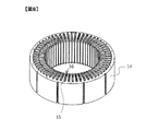
- FIG. 1 is a diagram showing an internal structure of an electric motor 1 according to an embodiment of the present invention.
- the electric motor 1 is a rotating electrical machine that converts electrical energy into rotational energy, and includes a housing 2, a stator (stator) 3, a rotor (rotor) 6, and a plurality of input terminals 8.
- the stator 3 is fixed to the inner peripheral surface of the housing 2 by shrink fitting or press fitting.
- the stator 3 includes a stator iron core 14 (see FIGS. 2 and 3) configured by laminating a plurality of electromagnetic steel plates, and a coil 9 wound inside the stator iron core 14.
- the stator 3 in the electric motor 1 of the present embodiment has a distributed winding structure in which the coil 9 is wound across a plurality of magnetic poles. At both ends in the axial direction of the stator core 14, coil ends 23 and 24 formed by projecting part of the coil 9 from the stator core 14 are arranged.
- the rotor 6 is disposed on the inner peripheral side of the stator 3.
- the rotor 6 is configured by integrating a rotor iron core (not shown) configured by laminating a plurality of electromagnetic steel plates and the shaft 5, and is rotatably supported by a bearing 7.
- a permanent magnet 4 made of rare earth or ferrite is attached to the outer peripheral surface of the rotor core.
- the surface magnet type rotor 6 was illustrated in FIG. 1, you may use the rotor of another form.
- it is possible to use various types of rotors such as an embedded magnet type rotor in which a permanent magnet is embedded in a groove or the like formed in the rotor core, or an induction type rotor in which a saddle-shaped conductor is incorporated.
- the input terminal 8 is electrically connected to the coil 9 respectively.
- a predetermined AC voltage is applied to each of the input terminals 8, an electric current flows through the coil 9 in the stator 3 to generate an AC magnetic field, and the rotor 6 is rotationally driven accordingly. Thereby, electric energy is converted into rotational energy (mechanical energy) in the electric motor 1.
- the coil 9 is configured by combining a plurality of conductor pieces (segment conductors) as described below.
- a stator structure using such segment conductors is widely used in small and high-efficiency motors for automobiles, such as motors for driving main machines and motors for auxiliary machines such as electric power steering and compressors for air conditioners. ing.
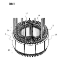
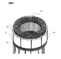
- FIG. 2 is a perspective view of the stator 3 according to an embodiment of the present invention when viewed from one coil end 24 side, that is, from the right side of FIG. 3 is a perspective view of the stator 3 according to an embodiment of the present invention when viewed from the other coil end 23 side, that is, from the left side of FIG.
- the stator 3 of the present embodiment is configured by incorporating a plurality of conductor pieces 11, 12, 13 having different shapes into the stator core 14.
- Each conductor piece 11, 12, 13 is formed by cutting and bending an electric wire, which is a conductor covered with an insulating film such as enamel, at a predetermined length.
- the cross-sectional shape of the electric wire in the conductor pieces 11, 12, 13 may be either a round cross section or a square cross section.
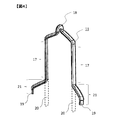
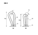
- FIG. 4 is a perspective view of the conductor piece 11.
- the conductor piece 11 has a hairpin shape by being bent approximately 180 ° at a bent portion 18 provided at the center portion. Therefore, hereinafter, the conductor piece 11 may be referred to as a “hairpin-shaped conductor piece”.
- the hairpin-shaped conductor piece 11 includes a pair of linear portions 17, a bent portion 18 formed between the pair of linear portions 17, and a pair formed on the side opposite to the bent portion 18 of the pair of linear portions 17. Terminal portion 19.
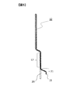
- FIG. 5 is a perspective view of the conductor piece 12.
- the conductor piece 12 is drawn from the stator iron core 14 on the coil end 24 side, whereby a lead wire is formed in the stator 3.
- the conductor piece 12 may also be referred to as “lead wire conductor piece”.
- the lead wire conductor piece 12 includes a straight portion 17 and a terminal portion 19 in addition to a portion forming a lead wire.
- FIG. 6 is a perspective view of the conductor piece 13.
- the conductor piece 13 forms a crossover that connects the separated conductor pieces, and has a shape different from that of the conductor pieces 11 and 12. Therefore, hereinafter, the conductor piece 13 may be referred to as a “deformed conductor piece”.
- the odd-shaped conductor piece 13 includes a pair of linear portions 17 and a pair of terminal portions 19 in addition to a portion that forms a crossover.
- FIG. 7 is a perspective view of the slot insulating paper 15 used when the conductor pieces 11, 12, 13 are incorporated in the stator core 14.
- the slot insulating paper 15 is formed using insulating paper having a thickness of about 80 ⁇ m, for example.
- FIG. 8 is a view showing a state in which the slot insulating paper 15 of FIG. 7 is assembled to each slot 16 of the stator core 14.
- the stator iron core 14 is provided with a plurality of slots 16, and a slot insulating paper 15 is attached in each slot 16.
- a plurality of hairpin-shaped conductor pieces 11, lead wire conductor pieces 12, and deformed conductor piece 13 linear portions 17 are respectively arranged inside the slots 16 via slot insulating paper 15.
- the coil end 24 is formed on one end face in the axial direction of the stator core 14.
- the bent portion 18 of the hairpin-shaped conductor piece 11 is disposed on the coil end 24 side. That is, FIG. 2 is a perspective view of the stator 3 with the side where the bent portion 18 of the hairpin-shaped conductor piece 11 is disposed as an upper surface.
- the straight line portion 17 extends to the end portion 19 in a straight line. And have an integrated shape.
- the end of each end portion 19 is inserted into each slot 16 from the coil end 24 side, and the opposite side of the stator core 14 in the axial direction. Protrude from. Thereafter, the protruding portions are bent into predetermined shapes, so that the portions indicated by reference numeral 21 in FIGS. 4, 5, and 6 are formed in the conductor pieces 11, 12, and 13, respectively, and placed in the slots 16.
- the straight line portion 17 and the terminal portion 19 protruding from the stator core 14 are formed.
- FIG. 3 is a perspective view of the stator 3 with the side where the terminal portions 19 of the conductor pieces 11, 12, and 13 are disposed as the upper surface.
- the stator 3 of the present embodiment realizes a short coil end by configuring the coil 9 using the conductor pieces 11, 12, and 13 that are segment conductors.
- the use of the hairpin-shaped conductor piece 11 avoids interference at portions of the coil ends 23 and 24 that straddle between the plurality of slots 16, and realizes a short coil end despite the distributed winding structure.
- a short coil end is realized by the structure of the stator 3 as described above.
- a further shortening of the coil end is realized by devising a structure when joining the terminal portions 19 of the conductor pieces 11, 12, 13. This will be described below.
- the stator used in the conventional electric motor has the following two problems with respect to further shortening of the coil end.
- problems when the conventional method is applied will be described using each configuration of the electric motor 1 described above.
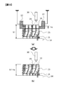
- FIG. 9 is a schematic diagram showing a welding method of the terminal portion 19 and a grounding method during welding according to a conventional method.
- the end portions 19 of two conductor pieces to be joined are fixed with clamps 22.
- the end portion 19 of the conductor piece on the outermost peripheral side (right side of FIG. 9) and the end portion 19 of the conductor piece on the inner side thereof are fixed by the clamp 22.
- a state is shown in which the end portion 19 of the conductor piece on the innermost peripheral side (left side in FIG. 9) and the end portion 19 of the conductor piece on the outermost side are fixed by the clamp 22.
- FIG. 10 is a schematic diagram showing the shape of the bent portion 18 of the hairpin-shaped conductor piece 11 according to the conventional method.
- 10A shows a state where the bent portion 18 is loosely bent
- FIG. 10B shows a state where the bent portion 18 is tightly bent.
- the inner radius when the bent portion 18 is loose is assumed to be ra and the height is assumed to be h2a.
- the inner radius when the bent portion 18 is tightly bent is rb (rb ⁇ ra), and the height is h2b (h2b ⁇ h2a). In this way, by tightly bending the bent portion 18, the height of the bent portion 18 is reduced, so that the height h 2 of the coil end 24 where the bent portion 18 is disposed can be reduced.
- a film crack 25 in which the insulating film is partially broken may occur mainly at the outer peripheral portion of the bending portion 18. .
- the dropped insulating film may be mixed into the electric motor 1 and cause a failure.
- a film crack 25 may occur if the inner radius of the bent portion 18 is about 1 mm, but the inner radius of the bent portion 18 may be increased. When it is 2 mm or more, the film crack 25 does not occur.
- the inner radius of the bent portion 18 in order to prevent the occurrence of the film crack 25, the inner radius of the bent portion 18 must be a certain value or more. In order to reduce the height h2 of the coil end 24 in which the bent portion 18 is disposed, it is required to reduce the inner radius of the bent portion 18 without generating the film crack 25.
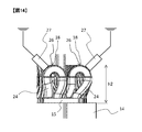
- FIG. 11 is a schematic diagram showing a grounding method during welding of the terminal portion 19 according to the first embodiment of the present invention.
- the conductor is exposed to the bent portion 18 of each hairpin-shaped conductor piece 11 at the coil end 24 where the bent portion 18 of the hairpin-shaped conductor piece 11 protrudes from the stator core 14.
- a portion 26 is provided.
- the conductor exposed portion 26 is a portion where the conductor is exposed from the insulating film by removing the insulating film of the material electric wire, like the conductor exposed portion of the terminal portion 19 described in FIG. Then, by bringing the electrode 27 into contact with each conductor exposed portion 26, the terminal portion 19 provided on the opposite side in the axial direction is electrically connected via the straight portion 17 (see FIG. 4) of each hairpin-shaped conductor piece 11. Is grounded.
- FIG. 12 is a diagram showing a shortening effect of the coil end 23 in the electric motor 1 according to the first embodiment of the present invention.
- (a) shows the welding method of the terminal portion 19 and the grounding method at the time of welding, as in FIG. 9, and (b) shows the electric motor according to the first embodiment of the present invention.
- 1 shows a welding method of the terminal portion 19 in FIG.
- a grounding clamp 22 is necessary when the terminal portion 19 is welded.
- the clamp 22 may not be abolished in the present embodiment.
- it is not necessary to ground the terminal portion 19 via the clamp 22 it is possible to reduce the axial height hc of the clamp 22 as compared with the conventional case.
- the conductor exposed portion 26 is provided in the bent portion 18 in the electric motor 1 of the present embodiment, the insulating film is partially broken when the bent portion 18 is bent, as described in FIG. Such a film crack 25 can be prevented from occurring. As a result, it is possible to downsize the bent portion 18 by tightly bending the bent portion 18 as compared with the conventional case, and as a result, it is possible to reduce the height h2 of the coil end 24 where the bent portion 18 is disposed. .
- the inner radius of the bent portion 18 is set to 2 mm or more in order to prevent the occurrence of the film crack 25 in the conventional method.
- the inner radius of the bent portion 18 is about 1 mm. Therefore, the height h2 of the coil end 24 can be shortened by about 1 mm as compared with the prior art.
- the electric motor 1 has a plurality of conductor pieces 11, 12, 13 formed by bending a conductor covered with an insulating film, and the plurality of conductor pieces 11. , 12, and 13 are provided in a plurality of slots 16 provided in the stator core 14, respectively, and the rotor 3 is provided on the inner peripheral side of the stator 3.
- the hairpin-shaped conductor piece 11 includes a pair of straight portions 17 disposed in the slot 16, a bent portion 18 formed between the pair of straight portions 17, and a side opposite to the bent portion 18 of the pair of straight portions 17. And a pair of terminal portions 19 joined to other conductor pieces.
- the pair of terminal portions 19 protrude from the stator core 14 at one end side in the axial direction of the stator core 14, and the bent portion 18 protrudes from the stator core 14 at the other end side in the axial direction of the stator core 14.
- the bent portion 18 has a conductor exposed portion 26 in which the conductor is exposed from the insulating film. Since it did in this way, since the terminal part 19 can be electrically grounded by making the electrode 27 contact the conductor exposed part 26 at the time of welding of the terminal part 19, the heights h1 and h2 of the coil ends 23 and 24 are shortened. It becomes possible to do. Therefore, the electric motor 1 can be reduced in size and efficiency.
- the second embodiment of the present invention will be described below with reference to FIG.
- the electric motor 1 in the present embodiment has the same structure as that described in the first embodiment except for the position where the conductor exposed portion 26 is provided in the hairpin-shaped conductor piece 11. Therefore, below, description other than the conductor exposed part 26 of the hairpin-shaped conductor piece 11 is abbreviate
- FIG. 13 is a schematic diagram showing a grounding method during welding of the terminal portion 19 according to the second embodiment of the present invention.
- the clamp 22 can be abolished or the height hc can be reduced when the terminal portion 19 is welded, so that the coil end on which the terminal portion 19 is disposed.
- the height h1 of 23 can be shortened.
- the bending part 18 can be reduced in size, the height h2 of the coil end 24 in which the bending part 18 is arrange
- positioned can be shortened.
- the conductor exposed portion 26 is provided at the bending top portion of the bending portion 18, but the position where the conductor exposed portion 26 is provided is not necessarily the bending top portion. Even if the conductor exposed portion 26 is provided in the vicinity of the bent top portion, the same effect can be obtained.
- the electric motor 1 has the same operational effects as the first embodiment.
- the bent portion 18 has a conductor exposed portion 26 in the bent top portion or the vicinity of the bent top portion farthest from the stator iron core 14. Since it did in this way, even if many bending parts 18 are densely arrange
- FIG. 14 is a schematic diagram showing a grounding method during welding of the terminal portion 19 according to the third embodiment of the present invention.
- the conductor exposed portion 26 is provided on the outer peripheral surface of the rotor, that is, the surface opposite to the stator core 14. Then, by bringing the electrode 27 into contact with each conductor exposed portion 26, it is provided on the opposite side in the axial direction via the straight portion 17 of each hairpin-shaped conductor piece 11 as in the first and second embodiments.
- the terminal portion 19 is electrically grounded.
- the clamp 22 can be abolished or the height hc can be reduced when the terminal 19 is welded, so that the terminal 19 is arranged.
- the height h1 of the coil end 23 can be shortened.
- the bending part 18 can be reduced in size, the height h2 of the coil end 24 in which the bending part 18 is arrange
- positioned can be shortened.
- the conductor exposed portion 26 is provided on the outer peripheral surface of the bent top portion of the bent portion 18, but the position where the conductor exposed portion 26 is provided is not necessarily the outer peripheral surface of the bent top portion. The same effect can be obtained even if the conductor exposed portion 26 is provided on the outer peripheral surface in the vicinity of the bent top portion.
- the electric motor 1 has the same operational effects as the first embodiment. Furthermore, the bent portion 18 has a conductor exposed portion 26 on the outer peripheral surface of the bent top portion farthest from the stator core 14 or on the outer peripheral surface in the vicinity of the bent top portion. As described above, as described in the second embodiment, the electrode 27 can be easily brought into contact with the conductor exposed portion 26 even if a large number of bent portions 18 are densely arranged on the coil end 24. Can be grounded.
- FIG. 15 is a schematic diagram showing a grounding method during welding of the terminal portion 19 according to the fourth embodiment of the present invention.
- the conductor exposed portion 26 is provided on the inner peripheral side or the outer peripheral side of the stator iron core 14.
- the conductor exposed portion 26 is provided on the inner peripheral side of the stator core 14 with respect to the bent top portion of the bent portion 18 of the hairpin-shaped conductor piece 11 disposed on the inner side of the stator 3, that is, on the left side of FIG. 15.
- the conductor exposed portion 26 is provided on the outer peripheral side of the stator core 14 with respect to the bent top portion. . Then, by bringing the electrode 27 into contact with each conductor exposed portion 26, the opposite side in the axial direction via the straight portion 17 of each hairpin-shaped conductor piece 11 as in the first, second, and third embodiments.
- the terminal portion 19 provided in the terminal is electrically grounded. In this case, even if the crossover portion of the deformed conductor piece 13 is disposed on the bent portion 18 of the hairpin-shaped conductor piece 11, this can be avoided and the electrode 27 can be brought into contact with each conductor exposed portion 26. .
- the terminal portion 19 It is possible to shorten the height h1 of the coil end 23 in which is disposed. Moreover, since the bending part 18 can be reduced in size, the height h2 of the coil end 24 in which the bending part 18 is arrange
- positioned can be shortened.
- the conductor exposed part 26 is provided so that the bending top part of the bending part 18 may be included, the position which provides the conductor exposed part 26 is not restricted to this. Even if the conductor exposed portion 26 is provided on the inner peripheral side or the outer peripheral side of the stator iron core 14 relative to the bent top portion without including the bent top portion, the same effect can be obtained.
- the electric motor 1 has the same operational effects as the first embodiment.
- the bent portion 18 has a conductor exposed portion 26 on the inner peripheral side or the outer peripheral side of the stator core 14 with respect to the bent top portion farthest from the stator core 14. Since it did in this way, even if obstructions, such as the crossover part of the irregular-shaped conductor piece 13, are arrange
- the conductor exposed portion 26 is formed in the extending direction of the conductor piece 11, That is, it is preferable to have a predetermined length, for example, a length of 1 mm or more, along the bending direction in the bent portion 18. If it does in this way, welding of the terminal part 19 can be implemented reliably.
- insulation may be ensured by covering the conductor exposed portion 26 with an insulator different from the insulating film of the conductor piece 11.
- a powder resin such as epoxy or a liquid resin can be used as an insulator covering the conductor exposed portion 26. If it does in this way, the safety
- the conductor exposed portion 26 where the conductor is exposed is formed by partially removing the insulating film from the conductor covered with the insulating film.
- the conductor in which the conductor exposed portions 26 are formed is bent, and the pair of straight portions 17, the bent portion 18 having the conductor exposed portions 26 formed between the pair of straight portions 17, and the pair of straight portions 17 are bent.
- a plurality of hairpin-shaped conductor pieces 11 each having a pair of terminal portions 19 respectively formed on the side opposite to the portion 18 are formed.
- a pair of linear portions 17 are respectively disposed in a plurality of slots 16 provided in the stator core 14, and a pair of terminal portions 19 are connected to the axis of the stator core 14.
- the coil ends as shown in FIGS. 2 and 3 are made to protrude from the stator core 14 at one end side in the direction and from the stator core 14 at the other end side in the axial direction of the stator core 14. 23 and 24 are formed.
- the conductor exposed portions 26 are electrically grounded and welded by the methods described in FIGS. 11, 13, 14, and 15, respectively, so that the terminal portions projecting from the stator iron core 14 on one end side. 19 are joined to the terminal portions 19 of the other conductor pieces, respectively.
- the stator 3 is configured in this manner, the electric motor 1 is manufactured.
Landscapes
- Engineering & Computer Science (AREA)
- Power Engineering (AREA)
- Manufacturing & Machinery (AREA)
- Manufacture Of Motors, Generators (AREA)
- Insulation, Fastening Of Motor, Generator Windings (AREA)
- Windings For Motors And Generators (AREA)
Abstract
La présente invention concerne un moteur électrique qui est pourvu : d'un stator qui comporte une pluralité de pièces conductrices formées par pliage d'un conducteur recouvert d'un film de revêtement isolant et est configuré par disposition de la pluralité de pièces conductrices respectivement dans une pluralité d'encoches ménagées dans un noyau de fer ; et d'un rotor disposé côté circonférence interne du stator. Les pièces conductrices comportent : une paire de parties linéaires disposées dans les encoches ; une partie courbée formée entre les deux parties linéaires ; et une paire de parties terminales formées du côté de la paire de parties linéaires opposé à la partie courbée et jointes à une autre des pièces conductrices. La paire de parties terminales font saillie du noyau de fer chacune d'un côté d'extrémité du noyau de fer dans la direction de l'arbre, et la partie courbée fait saillie du noyau de fer de l'autre côté d'extrémité du noyau de fer dans la direction de l'arbre et comporte une partie à conducteur dénudé dans laquelle le conducteur est dénudé du film de revêtement isolant.
Applications Claiming Priority (2)
| Application Number | Priority Date | Filing Date | Title |
|---|---|---|---|
| JP2018-100385 | 2018-05-25 | ||
| JP2018100385A JP2019205311A (ja) | 2018-05-25 | 2018-05-25 | 電動機、固定子、電動機の製造方法 |
Publications (1)
| Publication Number | Publication Date |
|---|---|
| WO2019225665A1 true WO2019225665A1 (fr) | 2019-11-28 |
Family
ID=68617051
Family Applications (1)
| Application Number | Title | Priority Date | Filing Date |
|---|---|---|---|
| PCT/JP2019/020334 Ceased WO2019225665A1 (fr) | 2018-05-25 | 2019-05-22 | Moteur électrique, stator, et procédé de fabrication de moteur électrique |
Country Status (2)
| Country | Link |
|---|---|
| JP (1) | JP2019205311A (fr) |
| WO (1) | WO2019225665A1 (fr) |
Cited By (1)
| Publication number | Priority date | Publication date | Assignee | Title |
|---|---|---|---|---|
| KR20210089502A (ko) * | 2020-01-08 | 2021-07-16 | 엘지전자 주식회사 | 회전 전기 기기의 스테이터 |
Families Citing this family (1)
| Publication number | Priority date | Publication date | Assignee | Title |
|---|---|---|---|---|
| JP7790038B2 (ja) * | 2021-06-22 | 2025-12-23 | 株式会社アイシン | ステータコイルの製造方法 |
Citations (2)
| Publication number | Priority date | Publication date | Assignee | Title |
|---|---|---|---|---|
| JP2004328861A (ja) * | 2003-04-23 | 2004-11-18 | Toyota Motor Corp | セグメントコイルの溶接方法およびアース治具 |
| JP2016174441A (ja) * | 2015-03-16 | 2016-09-29 | 日東シンコー株式会社 | スロットライナー |
-
2018
- 2018-05-25 JP JP2018100385A patent/JP2019205311A/ja active Pending
-
2019
- 2019-05-22 WO PCT/JP2019/020334 patent/WO2019225665A1/fr not_active Ceased
Patent Citations (2)
| Publication number | Priority date | Publication date | Assignee | Title |
|---|---|---|---|---|
| JP2004328861A (ja) * | 2003-04-23 | 2004-11-18 | Toyota Motor Corp | セグメントコイルの溶接方法およびアース治具 |
| JP2016174441A (ja) * | 2015-03-16 | 2016-09-29 | 日東シンコー株式会社 | スロットライナー |
Cited By (4)
| Publication number | Priority date | Publication date | Assignee | Title |
|---|---|---|---|---|
| KR20210089502A (ko) * | 2020-01-08 | 2021-07-16 | 엘지전자 주식회사 | 회전 전기 기기의 스테이터 |
| EP3916964A4 (fr) * | 2020-01-08 | 2022-11-09 | LG Magna e-Powertrain Co., Ltd. | Stator pour machine électrique tournante |
| US12057748B2 (en) | 2020-01-08 | 2024-08-06 | Lg Electronics Inc. | Stator for rotating electric machine |
| KR102714753B1 (ko) * | 2020-01-08 | 2024-10-10 | 엘지마그나 이파워트레인 주식회사 | 회전 전기 기기의 스테이터 |
Also Published As
| Publication number | Publication date |
|---|---|
| JP2019205311A (ja) | 2019-11-28 |
Similar Documents
| Publication | Publication Date | Title |
|---|---|---|
| EP1073179A2 (fr) | Enroulement pour stator sans encoche et méthode pour fabriquer un tel enroulement | |
| TWI536712B (zh) | Axial air gap type rotary motor | |
| US20110025164A1 (en) | Rotating electric machine and method for manufacturing stator | |
| JP6848132B1 (ja) | 回転電機の固定子 | |
| JP6253994B2 (ja) | ステータコイル、アキシャルギャップ型回転電機及びその製造方法 | |
| JPWO2020100311A1 (ja) | 固定子の製造方法 | |
| CN111245164A (zh) | 旋转电机及其制造方法 | |
| US10236735B2 (en) | Electric conductor for coil and rotating electric machine | |
| CN105723596A (zh) | 磁感应式电动机及其制造方法 | |
| WO2020196182A1 (fr) | Stator | |
| US11218035B2 (en) | Armature structure of three-phase motor | |
| CN110571965B (zh) | 旋转电机及其制造方法 | |
| WO2019225665A1 (fr) | Moteur électrique, stator, et procédé de fabrication de moteur électrique | |
| CN107078611A (zh) | 具有插接的扁平的卷绕头的转子或定子 | |
| JP2006187164A (ja) | 回転電機 | |
| JP7254140B1 (ja) | 回転電機 | |
| JP6279122B1 (ja) | 回転電機 | |
| US11223246B2 (en) | Stator | |
| JP6794590B1 (ja) | 回転電機の固定子および回転電機 | |
| JP6080964B2 (ja) | 回転電機の固定子 | |
| JP2004208464A (ja) | 電動機の巻線構造 | |
| US12308718B2 (en) | Molded coil, stator, and rotary electric machine | |
| US20150372551A1 (en) | Structure of stator | |
| JP2002136002A (ja) | 電動機 | |
| JP5256835B2 (ja) | 回転電機の固定子及び回転電機 |
Legal Events
| Date | Code | Title | Description |
|---|---|---|---|
| 121 | Ep: the epo has been informed by wipo that ep was designated in this application |
Ref document number: 19807612 Country of ref document: EP Kind code of ref document: A1 |
|
| NENP | Non-entry into the national phase |
Ref country code: DE |
|
| 122 | Ep: pct application non-entry in european phase |
Ref document number: 19807612 Country of ref document: EP Kind code of ref document: A1 |