WO2019230145A1 - Dispositif de chauffage de siège équipé d'un capteur - Google Patents
Dispositif de chauffage de siège équipé d'un capteur Download PDFInfo
- Publication number
- WO2019230145A1 WO2019230145A1 PCT/JP2019/011476 JP2019011476W WO2019230145A1 WO 2019230145 A1 WO2019230145 A1 WO 2019230145A1 JP 2019011476 W JP2019011476 W JP 2019011476W WO 2019230145 A1 WO2019230145 A1 WO 2019230145A1
- Authority
- WO
- WIPO (PCT)
- Prior art keywords
- sensor
- support
- region
- seat heater
- heater
- Prior art date
- Legal status (The legal status is an assumption and is not a legal conclusion. Google has not performed a legal analysis and makes no representation as to the accuracy of the status listed.)
- Ceased
Links
Images






Classifications
-
- B—PERFORMING OPERATIONS; TRANSPORTING
- B60—VEHICLES IN GENERAL
- B60N—SEATS SPECIALLY ADAPTED FOR VEHICLES; VEHICLE PASSENGER ACCOMMODATION NOT OTHERWISE PROVIDED FOR
- B60N2/00—Seats specially adapted for vehicles; Arrangement or mounting of seats in vehicles
- B60N2/56—Heating or ventilating devices
- B60N2/5678—Heating or ventilating devices characterised by electrical systems
- B60N2/5685—Resistance
-
- B—PERFORMING OPERATIONS; TRANSPORTING
- B60—VEHICLES IN GENERAL
- B60N—SEATS SPECIALLY ADAPTED FOR VEHICLES; VEHICLE PASSENGER ACCOMMODATION NOT OTHERWISE PROVIDED FOR
- B60N2/00—Seats specially adapted for vehicles; Arrangement or mounting of seats in vehicles
- B60N2/002—Seats provided with an occupancy detection means mounted therein or thereon
- B60N2/0021—Seats provided with an occupancy detection means mounted therein or thereon characterised by the type of sensor or measurement
- B60N2/003—Seats provided with an occupancy detection means mounted therein or thereon characterised by the type of sensor or measurement characterised by the sensor mounting location in or on the seat
- B60N2/0033—Seats provided with an occupancy detection means mounted therein or thereon characterised by the type of sensor or measurement characterised by the sensor mounting location in or on the seat mounted on or in the foam cushion
-
- A—HUMAN NECESSITIES
- A47—FURNITURE; DOMESTIC ARTICLES OR APPLIANCES; COFFEE MILLS; SPICE MILLS; SUCTION CLEANERS IN GENERAL
- A47C—CHAIRS; SOFAS; BEDS
- A47C7/00—Parts, details, or accessories of chairs or stools
- A47C7/62—Accessories for chairs
-
- A—HUMAN NECESSITIES
- A47—FURNITURE; DOMESTIC ARTICLES OR APPLIANCES; COFFEE MILLS; SPICE MILLS; SUCTION CLEANERS IN GENERAL
- A47C—CHAIRS; SOFAS; BEDS
- A47C7/00—Parts, details, or accessories of chairs or stools
- A47C7/62—Accessories for chairs
- A47C7/72—Adaptations for incorporating lamps, radio sets, bars, telephones, ventilation, heating or cooling arrangements or the like
- A47C7/74—Adaptations for incorporating lamps, radio sets, bars, telephones, ventilation, heating or cooling arrangements or the like for ventilation, heating or cooling
-
- B—PERFORMING OPERATIONS; TRANSPORTING
- B60—VEHICLES IN GENERAL
- B60N—SEATS SPECIALLY ADAPTED FOR VEHICLES; VEHICLE PASSENGER ACCOMMODATION NOT OTHERWISE PROVIDED FOR
- B60N2/00—Seats specially adapted for vehicles; Arrangement or mounting of seats in vehicles
- B60N2/56—Heating or ventilating devices
-
- B—PERFORMING OPERATIONS; TRANSPORTING
- B60—VEHICLES IN GENERAL
- B60N—SEATS SPECIALLY ADAPTED FOR VEHICLES; VEHICLE PASSENGER ACCOMMODATION NOT OTHERWISE PROVIDED FOR
- B60N2210/00—Sensor types, e.g. for passenger detection systems or for controlling seats
- B60N2210/10—Field detection presence sensors
- B60N2210/12—Capacitive; Electric field
-
- B—PERFORMING OPERATIONS; TRANSPORTING
- B60—VEHICLES IN GENERAL
- B60N—SEATS SPECIALLY ADAPTED FOR VEHICLES; VEHICLE PASSENGER ACCOMMODATION NOT OTHERWISE PROVIDED FOR
- B60N2210/00—Sensor types, e.g. for passenger detection systems or for controlling seats
- B60N2210/40—Force or pressure sensors
Definitions
- the present invention relates to a seat heater with a sensor.
- a seat heater with a sensor For the designated countries that are permitted to be incorporated by reference, the contents described in Japanese Patent Application No. 2018-105293 filed in Japan on May 31, 2018 are incorporated herein by reference. As part of
- a planar shape including a porous body, a pair of electrodes arranged at intervals in the porous body, and a PTC resistor provided between the electrodes A heating resistor is known (see, for example, Patent Document 1).
- a pair of flexible films each having a contact cell and a spacer having an opening are provided, and the contact cells are opposed to each other through the opening.
- a structure in which a flexible film and a spacer are laminated is known (for example, see Patent Document 2).
- both the seat heater and the seating sensor are installed on the seat, they are embedded in the seat in a stacked state.
- the stacking causes unevenness.
- a wadding having a thickness sufficient to absorb the unevenness is overlaid on the seat heater.
- this wading increases the power consumption of the seat heater because the distance from the seat surface to the seat heater increases, and the distance from the seat surface to the seating sensor also increases, so the detection accuracy of the seating sensor decreases. There is a problem that.
- the seating sensor is affixed to the seat pad, but the seating sensor is harder than the seat pad, and the seating sensor surface is smooth, whereas the seatpad surface is shaped into a seating surface. Has been. Therefore, there is also a problem that it is difficult to install the seating sensor on the seat pad.
- the problem to be solved by the present invention is to provide a seat heater with a sensor that is excellent in installation workability, while reducing power consumption and improving the detection accuracy of the sensor.
- a sheet heater with a sensor includes a sheet-like support including a core substrate having a plurality of through holes, a sensor unit provided in a first region of the support, and the support A heater portion provided in a second region different from the first region, wherein the sensor portion includes a first conductor portion, and the heater portion is provided on the support. And a sensor-equipped seat heater including a second conductor portion.
- the support includes an insulating layer covering a part of the core substrate, and the first region includes the insulating layer covering the core substrate in the support.
- the second region is a region where the insulating layer does not cover the core substrate in the support, and the first conductor portion is provided on the insulating layer, The two conductor portions may cover the core base material and also exist in the through hole.
- the support has an opening formed in the first region, and the first conductor portion includes a first electrode held on a first substrate, A second electrode held by a second substrate, wherein the first substrate is a second electrode of the support so that the first and second electrodes face each other through the opening. And the second substrate may be laminated on the second main surface of the support.
- the first conductor portion includes a first connection portion formed on the first main surface so as to surround the opening, and the second main surface so as to surround the opening.
- a second connection portion formed on the first electrode, an outer edge portion of the first electrode being in contact with the first connection portion, and an outer edge portion of the second electrode being in contact with the second connection portion. It may be in contact with the connecting portion.
- the support has a third region composed only of the core base material between the first region and the second region, and the core group The material may be exposed from between the sensor unit and the heater unit in the third region.
- the second conductor portion includes a pair of opposing wiring portions facing each other, and the heater portion includes a heating resistor having a higher electrical resistance than the second conductor portion.
- the heating resistor may include an interposition portion provided between the opposing wiring portions, and the interposition portion may cover the core base material.
- the second conductor portion penetrates the core base material through the through hole and covers both surfaces of the core base material, and the interposed portion of the heating resistor is also You may penetrate the said core base material through the said through-hole, and may cover both surfaces of the said core base material.
- the heating resistor may include a covering portion that covers the counter wiring portion and is integrally formed with the interposition portion.
- the heater portion may have a non-formed portion where the interposition portion is not provided between the opposing wiring portions.
- the second conductor portion includes a power supply wiring portion formed integrally with the counter wiring portion, a metal foil or a metal wire provided so as to overlap the power supply wiring portion, May be included.
- the seat heater with sensor includes first and second protective members laminated on both surfaces of the support body so as to cover the sensor section and the heater section, and the support body includes: It has the 4th field constituted only by the core base material in the outer edge part of the support, and the outer edge part of the 1st and 2nd protection members is the support member in the 4th field. It may be fixed to.
- the sensor unit and the heater unit are provided on the same support, it is possible to reduce the distance from the heater and the sensor to the sheet surface by thinning the padding, thereby saving power and detecting the sensor. The accuracy can be improved.
- the sensor unit and the heater unit are provided on the same support, and the sensor unit is provided on the support including a core base material having a plurality of through holes.
- the installation workability of the sensor-equipped seat heater including is excellent.
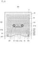
- FIG. 1A is a plan view showing a seat heater with a sensor in an embodiment of the present invention.
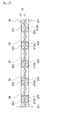
- 1B is a cross-sectional view taken along line IB-IB in FIG. 1A.
- FIG. 2A is a plan view showing a state in which a conductor is formed on a support in the embodiment of the present invention.
- 2B is a cross-sectional view taken along line IIB-IIB in FIG. 2A.
- FIG. 3A is a plan view showing a state in which a heater portion is formed in the embodiment of the present invention.
- 3B is a cross-sectional view taken along line IIIB-IIIB in FIG. 3A.
- FIG. 4A is a plan view showing a state in which a sensor unit is formed in the embodiment of the present invention.
- FIG. 4B is a cross-sectional view taken along the line IVB-IVB in FIG. 4A.
- FIG. 5 is a bottom view showing the first wiring board in the embodiment of the present invention.
- FIG. 6 is a partially enlarged plan view showing the core substrate in the embodiment of the present invention.
- FIG. 7 is a partially enlarged plan view showing a modification of the core substrate in the embodiment of the present invention.
- FIG. 8A is a plan view showing a first modification of the heater portion in the embodiment of the present invention.
- 8B is a cross-sectional view taken along line VIIIB-VIIIB in FIG. 8A.
- FIG. 9A is a plan view showing a second modification of the heater unit in the embodiment of the present invention.
- FIG. 9B is a cross-sectional view taken along line IXB-IXB in FIG. 9A.
- FIG. 10 is a cross-sectional view showing a modification of the sensor unit in the embodiment of the present invention.
- FIG. 11 is a cross-sectional view showing an installation example of the sensor-equipped seat heater in the embodiment of the present invention.
- FIGS. 1A and 1B are diagrams showing a sensor-equipped seat heater in the present embodiment
- FIGS. 2A and 2B are diagrams showing a state in which a conductor is formed on a support in the present embodiment
- FIGS. FIG. 4A and FIG. 4B are diagrams illustrating a state in which a sensor unit is formed in the present embodiment
- FIG. 5 is a diagram illustrating a first wiring board in the present embodiment.
- the sensor-equipped seat heater 1 includes a support 10, a sensor unit 20, a heater unit 30, and protective members 41 and 42 as shown in FIGS. 1A to 5.
- the sensor-equipped seat heater 1 is used by being embedded in a seat cushion 110 (see FIG. 11) of a seat 100 of a vehicle such as an automobile.
- the sensor unit 20 is a seating sensor that detects a pressure applied via the seat cushion 110 according to the seating of the occupant, and the presence / absence of the seating of the occupant on the seat 100 is determined based on the detection signal.
- the heater unit 30 heats the occupant by resistance heating a heating resistor 32 (described later) by energization.
- the determination result of the presence or absence of the seating of the occupant is used for a seat belt wearing request and a seat heater on / off determination.
- the support 10 is a flexible sheet-like member, and includes a core substrate 11 and an insulating layer 12.
- FIG. 6 is a partially enlarged plan view showing a core substrate in the present embodiment
- FIG. 7 is a partially enlarged plan view showing a modification of the core substrate in the embodiment.
- the core base material 11 is a woven fabric woven by weaving the woven yarns 111 and 112 in a plain weave, and has flexibility.
- the woven yarn constituting the core substrate 11 includes a warp 111 extending in the longitudinal direction and a weft 112 extending in a direction substantially orthogonal to the warp 111 (that is, in the lateral direction).
- the core base material 11 has a plurality of through holes (basket holes) 114 because it is formed by weaving the woven yarns 111 and 112 in a lattice shape.
- the through hole 114 is a gap (mesh) surrounded by the warp 111 and the weft 112 and penetrates the core base material 11 in the thickness direction of the core base material 11.
- the plurality of through holes 114 have substantially the same shape and substantially the same opening area, and are regularly and uniformly arranged in the core base material 11 in a plan view.
- the warp yarn 111 is constituted by bundling about 10 to 200 insulating fibers 111a having substantially the same diameter.
- the wefts 112 are each configured by bundling about 10 to 200 insulating fibers 112a having substantially the same diameter.
- Insulating fibers 111a and 112a in the present embodiment are both made of glass fibers and have substantially the same diameter of about 1 to 20 ⁇ m.
- the following configuration can be exemplified as an example of such a core substrate 11.
- the insulating fibers 111a of the warp 111 are made of glass fibers having a diameter of about 7 ⁇ m, and each warp 111 is made by bundling about 200 insulating fibers 111a.
- the insulating fibers 112a of the wefts 112 are also made of glass fibers having a diameter of about 7 ⁇ m, and each weft 112 is formed by bundling about 200 insulating fibers 112a.
- a woven fabric (glass cloth) having a thickness of about 0.1 mm is woven.
- the woven yarns 111 and 112 are woven in a plain weave so that the density of the warp yarns 111 is about 60 per 25 mm in the horizontal direction and the density of the weft yarns 112 is about 60 per 25 mm in the horizontal direction.
- a large number of through holes 114 having a rectangular opening shape of about 20 ⁇ m ⁇ 20 ⁇ m are present at a pitch of about 0.3 mm.
- the insulating fibers 111a and 112a are not particularly limited to the above glass fibers as long as they have electrical insulation and flexibility.
- the insulating fibers 111a and 112a may be made of resin fibers such as nylon fibers, rayon fibers, polyester fibers, polyamide fibers, vinyl fibers, and aramid fibers.
- the support body 10 may have a plurality of core base materials 11 laminated on each other.
- the core base material 11B is composed of a sheet-like non-woven fabric formed by bonding a large number of randomly oriented insulating fibers 113 to each other.
- the fiber 113 in this example is a glass fiber having a diameter of about 5 to 15 ⁇ m.
- the binder that binds the insulating fiber 113 include a resin material mainly composed of an acrylic resin or an epoxy resin. This binder bonds the insulating fibers 113 to each other at intersections. For this reason, gaps are formed between the insulating fibers 113, and a large number of through holes 114 are formed in the core base material 11B so as to penetrate linearly from the upper surface to the lower surface.
- the core substrate 11B has a thickness of about 50 to 100 ⁇ m and a porosity of about 75 to 90%. In addition, the thickness of the core base material 11B is not specifically limited, For example, you may have thickness of 30 micrometers or less.
- the insulating fiber 113 is not particularly limited to the glass fiber as long as it has electrical insulation and flexibility.
- the insulating fiber 113 may be made of resin fibers such as nylon fiber, rayon fiber, polyester fiber, polyamide fiber, vinyl fiber, and aramid fiber.
- the support body 10 may have a plurality of core base materials 11B laminated on each other.
- a porous body having an open cell structure such as a sponge may be used as the core substrate 11 instead of the woven fabric or nonwoven fabric.
- This porous body has a large number of through holes penetrating from the upper surface to the lower surface, and can be formed by foaming an organic material such as resin or rubber.
- the support 10 in the present embodiment has four regions 101 to 104 as shown in FIGS. 1B, 2B, 3B, and 4B.
- the first area 101 is an area where the sensor unit 20 is provided.
- the second region 102 is a region different from the first region 101 and is a region where the heater unit 30 is provided.
- the second region 102 surrounds the first region 101, that is, the heater unit 30 surrounds the sensor unit 20.
- the third region 103 is a region between the first region 101 and the second region 102, that is, a region between the sensor unit 20 and the heater unit 30.
- the fourth region 104 is an outer edge portion of the support 10 that surrounds the second region 102.
- the insulating layer 12 is provided in the first region 101, whereas the insulating layer 12 is not provided in the second to fourth regions 104.
- the sensor section 20 is provided in the first area 101 and the heater section 30 is provided in the second area 102, whereas the third area 103 and the fourth area 104 are The core base material 11 is used alone.
- an opening 105 penetrating the support 10 is formed in the first region 101.
- the pair of electrodes 223 and 233 of the sensor unit 20 face each other through the opening 105.
- the insulating layer 12 is directly formed on the core base material 11, covers the surface of the core base material 11, and closes the through holes 114 of the core base material 11. Yes.
- the insulating layer 12 is made of a resin material such as polyimide resin or epoxy resin, and has electrical insulation. This insulating layer 12 is formed in advance before forming the first conductor portion 21 of the sensor portion 20. For example, after the liquid resin is applied and impregnated in the second region 102 of the core base material 11. It is formed by performing a curing process.
- the method for applying the liquid resin is not particularly limited, and either a contact coating method or a non-contact coating method may be used.
- Specific examples of the contact coating method include screen printing, gravure printing, offset printing, gravure offset printing, flexographic printing, and the like.
- specific examples of the non-contact coating method include inkjet printing, spray coating method, dispense coating method, jet dispensing method and the like.
- the surface of the insulating layer 12 is flat compared to the surface of the core substrate 11, and the unevenness of the surface of the support 10 in the first region 101 is smoothed by the insulating layer 12. For this reason, in this embodiment, the pattern shape and thickness of the connection parts 211 and 212 of the sensor part 20 can be made uniform, and the connection parts 211 and 212 can be formed with high accuracy. Further, the insulating layer 12 closes the through hole 114 of the core base material 11. For this reason, when forming the connection parts 211 and 212 of the sensor part 20, the conductive paste is prevented from penetrating into the opposite surface of the core substrate 11 and conducting.
- an insulating layer is formed by sticking an electrically insulating film made of polyimide (PI), polyethylene terephthalate (PET) or the like to the core substrate 11 via an adhesive layer (or adhesive layer). 12 may be formed.
- the insulating layer 12 made of a film may be provided only on one surface of the core substrate 11.
- the sensor unit 20 is provided in the first region 101 of the support 10, and includes connection portions 211 and 212, a first wiring board 22, and a second wiring board. 23.
- the connecting portions 211 and 212 are directly formed on the insulating layer 12 and are provided on both surfaces of the support 10.
- the first wiring board 22 is laminated on the upper surface of the support body 10 in the first region 101, and the second wiring board 23 is placed on the lower surface of the support body 10 in the first region 101. Are stacked.
- connection part 211 is provided in the upper surface of insulating layer 12, as shown in Drawing 2A and Drawing 2B. Further, the second connection portion 212 is provided on the lower surface of the insulating layer 12. Both the first and second connecting portions 211 and 212 have an annular shape provided so as to surround the opening 105 of the support 10. The connection portions 211 and 212 are electrically insulated from each other by the insulating layer 12 of the support 10.
- the connecting portions 211 and 212 are made of, for example, conductive metal particles mainly composed of copper (Cu) or silver (Ag) and a binder resin, and have conductivity.
- the connection parts 211 and 212 may contain a plurality of types of conductive metal particles.
- connection portions 211 and 212 are formed by heating and baking the conductive paste applied to the support 10.
- the connection portions 211 and 212 are formed at the same time as the second conductor portion 31 (described later) of the heater portion 30.
- the conductive paste Does not penetrate (infiltrate) into the core substrate 11.
- the second conductor portion 31 of the heater portion 30 is directly formed on the core base material 11, the conductive paste penetrates (infiltrates) the core base material 11 and also exists in the through hole 114. .
- the conductive paste for forming the connecting portions 211 and 212 is a solution containing conductive metal particles and a binder resin that uniformly disperses the conductive metal particles.
- the conductive metal particles include conductive metal particles mainly composed of copper (Cu), silver (Ag), carbon (C), and the like.
- the binder resin include one or a mixture of two or more thermosetting resins such as polyhydric phenol compounds, phenol resins, alkyd resins, unsaturated polyester resins, and epoxy resins.
- an appropriate amount of an aqueous solvent or an alcohol such as ethanol, methanol or 2-propanol, or an organic solvent such as isophorone, terpineol, triethylene glycol monobutyl ether or butyl cellosolve acetate is added to the binder resin as a dispersion medium.
- the compounding quantity of this solvent is suitably adjusted according to the size, shape, film forming conditions, etc. of electroconductive metal particle.
- the heat source for curing the conductive paste is not particularly limited, but examples thereof include an electric heating oven, an infrared oven, a far infrared furnace (IR), a near infrared furnace (NIR), and a laser irradiation device. It may be a heat treatment combining these.
- the first wiring board 22 is a so-called membrane substrate. As shown in FIGS. 4A to 5, the first substrate 221, the first electrode 222, the first lead wiring 223, the connector 224, A cover lay 225.
- the first substrate 221 is made of a flexible insulating material such as polyethylene terephthalate (PET) or polyethylene naphthalate (PEN).
- PET polyethylene terephthalate
- PEN polyethylene naphthalate
- the first substrate 221 has a substantially T shape including a main body portion 221a and a tail portion 221b.
- the first electrode 222 has a circular planar shape, is provided at both ends of the main body portion 221 a of the first substrate 221, and is held by the first substrate 221.
- the first lead-out wiring 223 is led out from the first electrode 222 and extends to the end of the tail portion 221b.
- the connector 224 is mounted on the end of the tail portion 221b, and the first lead wire 223 is electrically connected to the connector 224.
- the connector 224 is electrically connected to a determination circuit that determines whether an occupant is seated on the seat 100 based on an on / off signal of the sensor unit 20. Note that the first electrode 222 and the connector 224 may be connected using, for example, an electric wire instead of the tail portion 221b and the first lead wiring 223.
- the first electrode 222 and the first lead wiring 223 are formed by applying a conductive paste such as a silver paste, a copper paste, or a carbon paste on the first base 221 and curing it.
- a method for applying the conductive paste to the first substrate 221 is not particularly limited, and any of the above-described contact application method or non-contact application method may be used. Moreover, the above-mentioned thing can be used as a heat source for hardening an electrically conductive paste.
- the first wiring board 22 is laminated on the upper surface of the support 10 so that the main body portion 221 a of the first substrate 221 faces the first region 101 of the support 10. At this time, the first electrode 222 faces the opening 105 of the support 10, and the outer edge portion of the first electrode 222 is in contact with the first connection portion 211 formed on the support 10. The first electrode 222 is provided on the support 10 through the first connection portion 211. Further, the main body portion 221 a of the first substrate 221 is fixed to the support body 10 through the adhesive layer 226.
- the tail portion 221b of the first substrate 221 is covered with the cover lay 225 and is not fixed to the support 10 and is in an unconstrained state.
- the coverlay 225 is made of a flexible insulating material such as polyethylene terephthalate (PET) or polyethylene naphthalate (PEN).
- the second wiring board 23 also includes a second substrate 231, a second electrode 232, a first lead wiring, a connector, and a cover lay. ing.
- the second wiring board 23 is laminated on the lower surface of the support body 10 so that the main body portion of the second substrate 231 faces the first region 101 of the support body 10. .
- the second electrode 232 faces the opening 105 of the support 10, and the outer edge portion of the second electrode 232 contacts the second connection portion 212 formed on the support 10.
- the second electrode 232 is provided on the support 10 through the second connection portion 221. Further, the main body portion of the second substrate 231 is fixed to the support 10 via the adhesive layer 236.
- the tail portion of the second substrate 231 is covered with a cover lay and is not fixed to the support 10 and is in an unconstrained state. Note that, depending on the circuit configuration of the sensor unit 20, the second substrate 231 of the second wiring board 23 may not have a tail portion.
- connection portions 211 and 212 and the electrodes 222 and 232 in the present embodiment correspond to an example of the first conductor portion in the present invention. That is, in the present embodiment, the connection portions 211 and 212 are directly provided on the support body 10, and the electrodes 222 and 232 are provided on the support body 10 via the connection portions 211 and 212.
- first connection portion 211 may be formed of an insulator
- second connection portion 212 may be formed of an insulator.
- the first electrode 222 is provided on the insulating layer 12 via the first connection portion 211
- the second electrode 232 is provided on the insulating layer 12 via the second connection portion 212. It is done. That is, in this example, the connecting portions 211 and 212 that are insulators constitute a part of the support 10, and the electrodes 222 and 232 are provided on the support 10. This corresponds to an example of one conductor portion.
- the first electrode 222 of the first wiring board 22 and the second electrode 232 of the second wiring board 23 face each other through the opening 105 of the support 10.
- the support 10 functions as a spacer for the seating sensor (pressure sensor). For this reason, when no occupant is seated on the seat 100, the support 10 maintains the distance between the first and second electrodes 222, 232, and the first and second electrodes 222, 232 are electrically connected. Therefore, an off signal is output from the sensor unit 20 to the determination circuit.
- the first wiring board 22 is pressed toward the second wiring board 23 along with the seating of the occupant on the seat 100, the first and second via the opening 105 of the support 10.
- the electrodes 222 and 232 are in contact with each other.
- the first and second electrodes 222 and 232 are electrically conducted, and an ON signal is output to the determination circuit via the connector 224.
- the first and second connection portions 211 and 212 are provided around the opening 105 of the support 10, the first and second wiring boards 22 and 23 can be pressed. The accompanying deformation of the support 10 is suppressed.
- the heater unit 30 is provided in the second region 102 of the support 10, and includes a second conductor unit 31 and a heating resistor 32.
- the second conductor portion 31 is formed directly on the core base material 11 of the support 10, exists in the through hole 114 of the core base material 11, and is provided on both surfaces of the core base material 11. .
- the heating resistor 32 is directly formed on the core base material 11 of the support 10, exists in the through hole 114 of the core base material 11, and is provided on both surfaces of the core base material 11. .
- 2nd conductor part 31 is provided with electric supply wiring parts 311a and 311b and counter wiring parts 312a and 312b, as shown in Drawing 2A and Drawing 2B.
- the first power supply wiring portion 311a is disposed in the vicinity of one end (the left end in the drawing) of the second region 102, and extends along the Y direction.
- the second power supply wiring portion 311b is also disposed in the vicinity of the other end (the right end in the drawing) of the second region 102 and extends along the Y direction.
- a plurality of first opposing wiring portions 312a are branched from the first power supply wiring portion 311a.
- the plurality of first opposing wiring portions 312a are arranged at substantially equal intervals along the extending direction (Y direction) of the first power supply wiring portion 311a, and the first power supply wiring portion 311a extends from the first power supply wiring portion 311a. It protrudes in a comb-tooth shape toward the second power supply wiring portion 311b.
- a plurality of second opposing wiring portions 312b are also branched from the second power supply wiring portion 311b.
- the plurality of second opposing wiring portions 312b are arranged at substantially equal intervals along the extending direction (Y direction) of the second power supply wiring portion 311b, and the second power supply wiring portion 311b extends from the second power supply wiring portion 311b. It protrudes in a comb-tooth shape toward one power supply wiring portion 311a.
- the first opposing wiring portions 312a and the second opposing wiring portions 312b are alternately arranged and face each other with a predetermined interval.
- a predetermined interval is also formed between the tip of the first opposing wiring portion 312a and the second power supply wiring portion 311b, and the tip of the second opposing wiring portion 312b and the first power supply wiring portion.
- a predetermined interval is also formed between 311a.
- the opposing wiring portions 312a and 312b that directly contact the heating resistor 32 and contribute to resistance heating are separated from the feeding wiring portions 311a and 311b that contribute to feeding power to the opposing wiring portions 312a and 312b. Therefore, it is possible to deal with various shapes of the heat generating area, and the degree of freedom in design is improved.
- planar shapes of the power supply wiring portions 311a and 311b and the opposing wiring portions 312a and 312b are not particularly limited to the above, and can be arbitrarily set.
- the planar shape of the power supply wiring portions 311a and 311b may be a curved shape or a meandering shape, or the opposing wiring portions 312a and 312b
- the planar shape may be a curved shape or a meandering shape.
- the second conductor portion 31 is composed of, for example, conductive metal particles mainly composed of copper (Cu) or silver (Ag) and a binder resin, like the connection portions 211 and 212 described above. It has electrical conductivity.
- the second conductor portion 31 is formed at the same time as the connection portions 211 and 212 described above.
- the second conductor portion 31 is not limited to this, and the second conductor portion 31 is separated from the connection portions 211 and 212. You may form by the process.
- the second conductor portion 31 is formed directly on the core base material 11, and when the conductive paste is applied to the core base material 11, the conductive paste penetrates the core base material 11 ( Infiltration). For this reason, the second conductor portion 31 also exists in the through hole 114, and penetrates the core base material 11 through the through hole 114 and covers both surfaces of the core base material 11. The second conductor portion 31 may cover only one side of the core base material 11.
- the heating resistor 32 is a resistor that generates heat when a voltage is applied, and is provided over the entire second region 102 of the support 10 so as to cover the second conductor portion 31.
- the heating resistor 32 is formed by applying a resistor paste to the core substrate 11 and curing it.
- the heating resistor 32 is formed directly on the core base material 11, similarly to the second conductor portion 31 described above.
- the resistor paste becomes the core base. It also exists in the through hole 114 of the material 11. For this reason, the heating resistor 32 is also present in the through hole 114 and penetrates the core base material 11 through the through hole 114 and covers both surfaces of the core base material 11. Note that the heating resistor 32 may cover only one side of the core base material 11.
- the resistor paste in this embodiment is a high resistance conductive paste.
- a paste containing a crystalline resin, a binder resin, and a conductor can be exemplified.
- the crystalline resin include polyolefin resins and vinyl resins.
- the binder resin include synthetic rubbers such as isopropylene rubber, butadiene rubber, nitrile rubber, ethylene propylene rubber, and silicon rubber, or thermoplastic elastomers.
- Examples of the conductor include carbon and graphite.
- the heating resistor 32 is in direct contact with the second conductor portion 31 formed on the core base material 11 and includes an interposition portion 321 and a covering portion 322.
- the intervening portion 321 is a portion interposed between the opposing wiring portions 312a and 312b facing each other, and is a portion contributing to heat generation.
- the intervening portion 321 is also present in the through hole 114 and penetrates the core base material 11 through the through hole 114 and covers both surfaces of the core base material 11.
- the covering portion 322 is a portion interposed between the interposed portions 321 and has a function of protecting the opposing wiring portions 312a and 312b by covering the opposing wiring portions 312a and 312b.
- the interposition part 321 and the covering part 322 are integrally formed.
- an opening 323 is formed in a portion of the heating resistor 32 corresponding to the end portions of the power supply wiring portions 311a and 311b, and the end portions of the power supply wiring portions 311a and 311b are formed through the opening 323.
- the heating resistor 32 is exposed.
- the crimp terminal 351 of the wire harness 35 is connected to the power supply wiring portions 311a and 311b through the opening 323.
- One end of an electric wire 352 is connected to the crimp terminal 351, and a connector 353 is connected to the other end of the electric wire 352.
- the heater unit 30 is connected to a power supply source (not shown) via a connector 353 of the wire harness 35.
- the second conductor portion 31 exists in the through hole 114 of the core base material 11 and is provided on both surfaces of the core base material 11, A large cross-sectional area is secured. For this reason, even when the wiring becomes longer as the heater area becomes larger, the increase in the electric resistance value of the second conductor portion 31 is alleviated and the power supply amount in the entire heater portion 30 is leveled. Can be achieved.
- the interposed portion 321 of the heating resistor 32 exists in the through hole 114 and is provided on both surfaces of the core base material 11, a large cross-sectional area of the heating resistor 32 is ensured. Therefore, it is possible to improve the temperature rising rate and make the heat generation uniform. Moreover, since the heating resistor 32 has a symmetrical structure, it is possible to improve the resistance against thermal deformation of the sensor-equipped seat heater 1.
- the covering portion 322 covers the opposing wiring portions 312a and 312b, the opposing wiring portions 311a and 312b are protected.
- the covering portion 322 is formed integrally with the interposition portion 321, the fixing force of the second conductor portion 31 to the core base material 11 is improved and the second conductor portion 31 and the heating resistor 32 are It is also possible to increase the contact area.
- the support 10 is composed only of the core base material 11 between the first region 101 where the sensor unit 20 is provided and the second region 102 where the heater unit 30 is provided.
- a third region 103 is provided. In the third region 103, the core base material 11 is exposed from between the sensor unit 20 and the heater unit 30.
- the third region 103 functions as a tropical zone.
- the heat transfer from the heater part 30 to the sensor part 20 can be suppressed, and the detection accuracy of the sensor part 20 can be stabilized.
- the third region 103 having a width of 5 mm, the temperature of the sensor unit 20 can be suppressed to less than 40 ° C. when the heater unit 30 generates heat up to 80 ° C.
- 8A and 8B are a plan view and a cross-sectional view showing a first modification of the heater portion in the present embodiment. 8A and 8B correspond to FIGS. 2A and 2B, respectively, and the heating resistor 32 and the protection members 41 and 42 are not shown in FIGS. 8A and 8B.
- the 2nd conductor part 31 may be provided with the strip
- the metal foil 33 is made of, for example, a metal material excellent in conductivity such as copper, aluminum, or an alloy thereof, and has a thickness of about 35 ⁇ m, although not particularly limited.
- a fine wire or a conductive yarn obtained by winding a metal foil around a resin fiber may be used.
- the metal foil 33 is provided so as to overlap the power supply wiring portions 311 a and 311 b of the second conductor portion 31.
- the metal foil 33 is disposed on the core base material 11 in the second region 102 before forming the power supply wiring portions 311a and 311b, and the power supply wiring portion is formed on the core base material 11 so as to cover the metal foil 33.
- the metal foil 33 and the power supply wiring portions 311a and 311b are connected.
- the wire 352 of the wire harness 35 is directly solder-connected to the metal foil 33 by forming the opening 313 in the power supply wiring portions 311a and 311b. May be.
- the metal foil 33 By superimposing the metal foil 33 on the power supply wiring portions 311a and 311b, even if the wiring becomes longer as the heater area increases, the electric resistance value of the power supply wiring portions 311a and 311b increases. Can be further relaxed, and the power supply amount in the entire heater section 30 can be further leveled.
- 9A and 9B are a plan view and a cross-sectional view showing a second modification of the heater portion in the present embodiment.
- 9A and 9B correspond to FIGS. 3A and 3B, respectively, and the protection members 41 and 42 are not shown in FIGS. 9A and 9B.
- the heater section 30 may have a non-formed portion 34 where the heating resistor 32 is not formed between the opposing wiring sections 312a and 312b facing each other. From this non-formation part 34, the core base material 11 of the support body 10 is exposed. Since the non-formed portion 34 blocks electrical conduction between the opposing wiring portions 312a and 312b facing each other, the non-formed portion 34 does not generate heat.
- four slit-shaped non-formed portions 34 are provided in the upper region of the heater portion 30 in the drawing, and these non-formed portions 34 are generally semicircular as a whole. It has a shape.
- the non-formed portion 34 corresponds to the gap between the thighs of the occupant, and prohibits heat generation in the portion corresponding to the heating unnecessary portion in the heating resistor 32. That is, in this example, power saving is achieved by approximating the shape of the area that generates heat in the heater unit 30 to the shape of the portion requiring heating.
- the shape of the non-formation part 34 is not specifically limited.
- the interposition portion 31 is not formed and only the core base material 11 is present, so that the flexibility of the heat generating resistor portion 32 is also improved.
- FIG. 10 is a cross-sectional view showing a modification of the sensor unit in the present embodiment.
- the protection members 41 and 42 are not shown.
- the sensor element 50 is inserted into the through hole 114 of the support 10, and the sensor element 50 is interposed between the first and second electrodes 222, 232 of the first and second wiring boards 22, 23. 50 may be interposed.
- the sensor element 50 has electrodes on the upper and lower surfaces thereof, and these electrodes are electrically connected to the first and second electrodes 222 and 232.
- a pressure sensitive rubber, a piezo element, etc. which can detect a pressure change continuously can be illustrated.
- the first and second wiring boards 22 and 23 are so-called flexible printed wiring boards. That is, in the first and second wiring boards 22 and 23, for example, the first and second substrates 221 and 231 are made of polyimide, and the first and second electrodes 222 and 232 are made of copper foil. It is formed by patterning. Furthermore, in this example, in order to ensure connection reliability between the sensor element 50 and the electrodes 222 and 232, the first and second electrodes 222 and 232 are covered with a gold plating layer.
- the first and second protection members 41 and 42 cover the entire surface of the support 10, and are attached to the core substrate 11 of the support 10 in the fourth region 104.
- the sensor-equipped seat heater 1 of the present embodiment has a fixing portion 43 formed by fixing the protection members 41 and 42 to the core base material 11 at the outer edge portion.
- the sensor-equipped seat heater 1 may not include the first and second protection members 41 and 42.
- such protective members 41 and 42 for example, a needle felt (nonwoven fabric) made of polyester fiber and having a thickness of about 1.0 mm can be exemplified.
- adhesive agents such as a silicon-type resin, can be illustrated, for example.
- the protection members 41 and 42 you may use the nonwoven fabric or woven fabric which consists of fibers other than polyester.
- a non-woven fabric containing carbon fibers having high thermal conductivity may be used as the protective member 41 on the seat skin 120 side of the seat cushion 110.
- the heat propagation loss at the time of heater operation can be reduced and heating performance can be improved.
- the wadding 140 under the seat cover 120 may be unnecessary.
- a non-woven fabric having a surface with a large friction coefficient may be used as the protective member 42 on the seat pad 130 side of the seat cushion 110.
- a non-woven fabric having a surface with a large friction coefficient may be used as the protective member 42 on the seat pad 130 side of the seat cushion 110.
- the protective members 41 and 42 are configured by using fibers having hot-melt adhesive properties such as polypropylene (PP), polyethylene (PE), polyamide (PA), and the like.
- the protective members 41 and 42 may be affixed to the core substrate 11 by partially melting.
- the sensor-equipped seat heater 1 can be directly sewn to the back surface of the seat skin 120 of the seat 100 with the fixing portion 43. It is possible to improve accuracy and suppress positional deviation during use.
- FIG. 11 is a cross-sectional view showing an installation example of the seat heater with a sensor in the present embodiment.
- the sensor-equipped seat heater 1 described above is installed on a seat 100 of a vehicle such as an automobile as shown in FIG.
- the seat 100 includes, for example, a seat cushion 110 that supports an occupant's buttocks seated on the seat 100 and a seat back 150 that supports an occupant's back.
- the seat back 150 is equipped with a headrest 160 that supports the head of the occupant.
- the sensor unit 20 of the sensor-equipped seat heater 1 is The second electrodes 222 and 232 are electrically connected to each other, and an ON signal is output to the determination circuit via the connector 224.
- the sensor unit 20 and the heater unit 30 are provided on the same support body 10 and there is no unevenness due to lamination, so that even if the wadding 140 is thinned, the passenger is uncomfortable. There is no end. Therefore, the detection accuracy of the sensor unit 20 that can reduce the distance D from the surface of the sheet 100 to the sensor unit 20 can be improved.
- the heater section 30 of the sensor-equipped seat heater 1 warms the occupant by resistance-heating the heating resistor 32 by energizing the opposing wiring sections 321a and 321b.
- the distance D from the surface of the sheet 100 to the heater unit 30 can be reduced by thinning the padding 140. it can. Thereby, the heat propagation loss is reduced, and the occupant can be efficiently heated by the heater unit 30, so that power saving can be achieved.
- the sensor unit 20 and the heater unit 30 are provided on the same support body 10, and the support body 10 has a core substrate 11 having a large number of through holes. For this reason, the workability of installation work is improved in the sensor-equipped seat heater 1 including the sensor unit 20.
- the sensor-equipped seat heater installed on the vehicle seat 100 has been described.
- the use of the sensor-equipped seat heater 1 is not particularly limited to the vehicle, for example, a seat used outside the vehicle, It may be used for a bed or the like.
- the sensor unit 20 configures the seating sensor has been described, but the present invention is not particularly limited thereto.
- the sensor unit 20 may constitute a capacitance sensor or the like.
- the first conductor portion is configured by the connection portions 211 and 212 and the electrodes 222 and 232.
- the present invention is not particularly limited thereto.
- FIG. In this case, the sensor unit 20 may not include the first substrate 221 and the second substrate 231.
Landscapes
- Engineering & Computer Science (AREA)
- Aviation & Aerospace Engineering (AREA)
- Transportation (AREA)
- Mechanical Engineering (AREA)
- Surface Heating Bodies (AREA)
- Chair Legs, Seat Parts, And Backrests (AREA)
- Seats For Vehicles (AREA)
Abstract
La présente invention concerne un dispositif de chauffage de siège équipé d'un capteur (1) qui comprend un support en forme de feuille (10) contenant un matériau de base de noyau (11) comportant une pluralité de trous traversants (114), une unité de capteur (20) disposée dans une première région (101) du support, et une unité de chauffage (30) disposée dans le support, dans une deuxième région (102) qui est différente de la première région. L'unité de capteur contient une première partie conductrice (21). L'unité de chauffage contient une deuxième partie conductrice (31) disposée sur le support.
Applications Claiming Priority (2)
| Application Number | Priority Date | Filing Date | Title |
|---|---|---|---|
| JP2018-105293 | 2018-05-31 | ||
| JP2018105293A JP2019208656A (ja) | 2018-05-31 | 2018-05-31 | センサ付きシートヒータ |
Publications (1)
| Publication Number | Publication Date |
|---|---|
| WO2019230145A1 true WO2019230145A1 (fr) | 2019-12-05 |
Family
ID=68696914
Family Applications (1)
| Application Number | Title | Priority Date | Filing Date |
|---|---|---|---|
| PCT/JP2019/011476 Ceased WO2019230145A1 (fr) | 2018-05-31 | 2019-03-19 | Dispositif de chauffage de siège équipé d'un capteur |
Country Status (2)
| Country | Link |
|---|---|
| JP (1) | JP2019208656A (fr) |
| WO (1) | WO2019230145A1 (fr) |
Cited By (1)
| Publication number | Priority date | Publication date | Assignee | Title |
|---|---|---|---|---|
| EP4380307A1 (fr) * | 2022-11-15 | 2024-06-05 | Lisa Dräxlmaier GmbH | Procédé de fabrication d'un élément intérieur pour un véhicule |
Families Citing this family (1)
| Publication number | Priority date | Publication date | Assignee | Title |
|---|---|---|---|---|
| US20230064831A1 (en) * | 2020-01-30 | 2023-03-02 | Liquid X Printed Metals, Inc. | Force sensor controlled conductive heating elements |
Citations (2)
| Publication number | Priority date | Publication date | Assignee | Title |
|---|---|---|---|---|
| JP2003109803A (ja) * | 2001-09-28 | 2003-04-11 | Matsushita Electric Ind Co Ltd | 柔軟性ptc面状発熱体、及びその製造方法 |
| JP2008018057A (ja) * | 2006-07-13 | 2008-01-31 | Aisin Seiki Co Ltd | シートヒータ |
-
2018
- 2018-05-31 JP JP2018105293A patent/JP2019208656A/ja active Pending
-
2019
- 2019-03-19 WO PCT/JP2019/011476 patent/WO2019230145A1/fr not_active Ceased
Patent Citations (2)
| Publication number | Priority date | Publication date | Assignee | Title |
|---|---|---|---|---|
| JP2003109803A (ja) * | 2001-09-28 | 2003-04-11 | Matsushita Electric Ind Co Ltd | 柔軟性ptc面状発熱体、及びその製造方法 |
| JP2008018057A (ja) * | 2006-07-13 | 2008-01-31 | Aisin Seiki Co Ltd | シートヒータ |
Cited By (1)
| Publication number | Priority date | Publication date | Assignee | Title |
|---|---|---|---|---|
| EP4380307A1 (fr) * | 2022-11-15 | 2024-06-05 | Lisa Dräxlmaier GmbH | Procédé de fabrication d'un élément intérieur pour un véhicule |
Also Published As
| Publication number | Publication date |
|---|---|
| JP2019208656A (ja) | 2019-12-12 |
Similar Documents
| Publication | Publication Date | Title |
|---|---|---|
| US10442273B2 (en) | Heatable interior lining element | |
| WO2020066121A1 (fr) | Capteur de capacité, son procédé de fabrication, et électrode souple réticulée pour capteur de capacité | |
| US20200189428A1 (en) | Sheet-type heating element and armrest of vehicle door including the same | |
| US11873213B2 (en) | Electrostatic-type transducer and manufacturing method thereof | |
| WO2017006303A1 (fr) | Dispositif de chauffage à chaleur rayonnante pour véhicule | |
| US10960732B2 (en) | Heater device | |
| CN109952810B (zh) | 辐射加热装置 | |
| WO2013087511A1 (fr) | Élément chauffant ohmique de type feuille | |
| WO2019230145A1 (fr) | Dispositif de chauffage de siège équipé d'un capteur | |
| CN113647118B (zh) | 静电型换能器以及静电型换能器单元 | |
| CN100521834C (zh) | 导电材料 | |
| JPH10335051A (ja) | 便座ヒータ | |
| WO2019230146A1 (fr) | Dispositif de chauffage de siège | |
| KR102037836B1 (ko) | 차량용 시트에 사용되는 발열 패드 및 그의 제조 방법 | |
| US20220167465A1 (en) | Flexible and stretchable electric heater based on electrically conductive textile material and method of manufacturing same | |
| JP5444886B2 (ja) | 車両用シートの表皮材 | |
| CN116324357A (zh) | 压敏传感器 | |
| JPH1197160A (ja) | 面状発熱体 | |
| CN101578913B (zh) | 片状发热元件 | |
| KR102050981B1 (ko) | 열전도성 접착 시트가 적층되는 차량용 시트의 발열 패드 및 그의 제조 방법 | |
| JP2011004936A (ja) | 車両用シートの表皮材 | |
| JP7546140B2 (ja) | 面状発熱体 | |
| JP2021089840A (ja) | 面状発熱体 | |
| JPS6230304Y2 (fr) | ||
| JP4729862B2 (ja) | 面状発熱体 |
Legal Events
| Date | Code | Title | Description |
|---|---|---|---|
| 121 | Ep: the epo has been informed by wipo that ep was designated in this application |
Ref document number: 19811718 Country of ref document: EP Kind code of ref document: A1 |
|
| NENP | Non-entry into the national phase |
Ref country code: DE |
|
| 122 | Ep: pct application non-entry in european phase |
Ref document number: 19811718 Country of ref document: EP Kind code of ref document: A1 |