WO2019230896A1 - Bras robotisé et robot pourvu de celui-ci - Google Patents
Bras robotisé et robot pourvu de celui-ci Download PDFInfo
- Publication number
- WO2019230896A1 WO2019230896A1 PCT/JP2019/021561 JP2019021561W WO2019230896A1 WO 2019230896 A1 WO2019230896 A1 WO 2019230896A1 JP 2019021561 W JP2019021561 W JP 2019021561W WO 2019230896 A1 WO2019230896 A1 WO 2019230896A1
- Authority
- WO
- WIPO (PCT)
- Prior art keywords
- robot
- robot arm
- end portion
- inner diameter
- end effector
- Prior art date
- Legal status (The legal status is an assumption and is not a legal conclusion. Google has not performed a legal analysis and makes no representation as to the accuracy of the status listed.)
- Ceased
Links
Images

Classifications
-
- B—PERFORMING OPERATIONS; TRANSPORTING
- B25—HAND TOOLS; PORTABLE POWER-DRIVEN TOOLS; MANIPULATORS
- B25J—MANIPULATORS; CHAMBERS PROVIDED WITH MANIPULATION DEVICES
- B25J11/00—Manipulators not otherwise provided for
- B25J11/0075—Manipulators for painting or coating
-
- B—PERFORMING OPERATIONS; TRANSPORTING
- B05—SPRAYING OR ATOMISING IN GENERAL; APPLYING FLUENT MATERIALS TO SURFACES, IN GENERAL
- B05B—SPRAYING APPARATUS; ATOMISING APPARATUS; NOZZLES
- B05B13/00—Machines or plants for applying liquids or other fluent materials to surfaces of objects or other work by spraying, not covered by groups B05B1/00 - B05B11/00
- B05B13/02—Means for supporting work; Arrangement or mounting of spray heads; Adaptation or arrangement of means for feeding work
- B05B13/04—Means for supporting work; Arrangement or mounting of spray heads; Adaptation or arrangement of means for feeding work the spray heads being moved during spraying operation
- B05B13/0431—Means for supporting work; Arrangement or mounting of spray heads; Adaptation or arrangement of means for feeding work the spray heads being moved during spraying operation with spray heads moved by robots or articulated arms, e.g. for applying liquid or other fluent material to three-dimensional [3D] surfaces
- B05B13/0433—Means for supporting work; Arrangement or mounting of spray heads; Adaptation or arrangement of means for feeding work the spray heads being moved during spraying operation with spray heads moved by robots or articulated arms, e.g. for applying liquid or other fluent material to three-dimensional [3D] surfaces the work being vehicle components, e.g. vehicle bodies
-
- B—PERFORMING OPERATIONS; TRANSPORTING
- B25—HAND TOOLS; PORTABLE POWER-DRIVEN TOOLS; MANIPULATORS
- B25J—MANIPULATORS; CHAMBERS PROVIDED WITH MANIPULATION DEVICES
- B25J15/00—Gripping heads and other end effectors
- B25J15/0019—End effectors other than grippers
-
- B—PERFORMING OPERATIONS; TRANSPORTING
- B25—HAND TOOLS; PORTABLE POWER-DRIVEN TOOLS; MANIPULATORS
- B25J—MANIPULATORS; CHAMBERS PROVIDED WITH MANIPULATION DEVICES
- B25J18/00—Arms
-
- B—PERFORMING OPERATIONS; TRANSPORTING
- B25—HAND TOOLS; PORTABLE POWER-DRIVEN TOOLS; MANIPULATORS
- B25J—MANIPULATORS; CHAMBERS PROVIDED WITH MANIPULATION DEVICES
- B25J19/00—Accessories fitted to manipulators, e.g. for monitoring, for viewing; Safety devices combined with or specially adapted for use in connection with manipulators
- B25J19/0025—Means for supplying energy to the end effector
-
- B—PERFORMING OPERATIONS; TRANSPORTING
- B25—HAND TOOLS; PORTABLE POWER-DRIVEN TOOLS; MANIPULATORS
- B25J—MANIPULATORS; CHAMBERS PROVIDED WITH MANIPULATION DEVICES
- B25J19/00—Accessories fitted to manipulators, e.g. for monitoring, for viewing; Safety devices combined with or specially adapted for use in connection with manipulators
- B25J19/0025—Means for supplying energy to the end effector
- B25J19/0029—Means for supplying energy to the end effector arranged within the different robot elements
-
- B—PERFORMING OPERATIONS; TRANSPORTING
- B25—HAND TOOLS; PORTABLE POWER-DRIVEN TOOLS; MANIPULATORS
- B25J—MANIPULATORS; CHAMBERS PROVIDED WITH MANIPULATION DEVICES
- B25J19/00—Accessories fitted to manipulators, e.g. for monitoring, for viewing; Safety devices combined with or specially adapted for use in connection with manipulators
- B25J19/0075—Means for protecting the manipulator from its environment or vice versa
-
- B—PERFORMING OPERATIONS; TRANSPORTING
- B25—HAND TOOLS; PORTABLE POWER-DRIVEN TOOLS; MANIPULATORS
- B25J—MANIPULATORS; CHAMBERS PROVIDED WITH MANIPULATION DEVICES
- B25J19/00—Accessories fitted to manipulators, e.g. for monitoring, for viewing; Safety devices combined with or specially adapted for use in connection with manipulators
- B25J19/0075—Means for protecting the manipulator from its environment or vice versa
- B25J19/0079—Means for protecting the manipulator from its environment or vice versa using an internal pressure system
Definitions
- the present invention relates to a robot arm and a robot including the same.
- a work tool such as a gripper or a welding torch is attached to the wrist end of the robot arm of Patent Document 1.
- the wrist mainly includes a wrist machine frame and a wrist inner frame attached to the wrist machine frame so as to be rotatable about the J5 axis.
- the wrist inner frame includes a work tool mounting portion, and is rotated around the J6 axis together with the work tool.
- a conventional robot arm is generally provided with a cylindrical housing that defines a peripheral edge of an internal space serving as a passage for a plurality of elongated members (for example, wiring, piping, etc.).
- a plurality of elongated members for example, wiring, piping, etc.
- an attachment structure for attaching an end effector is provided at the tip of the internal space of the cylindrical casing.
- the attachment structure includes an insertion hole formed corresponding to each of the plurality of long members to insert each of the plurality of long members, and each of the plurality of long members to the insertion holes. And a fixing member for fixing.
- the robot arm that has been miniaturized has a small cylindrical housing and its internal space.
- the mounting structure since it is difficult for the mounting structure to reduce the diameter of the fixing member, it is difficult to downsize the main part structure.
- each of the plurality of long members suddenly bends toward the outside in the radial direction of the cylindrical casing from the internal space of the cylindrical casing to the insertion hole of the mounting structure. By bending in this way, each of the plurality of long members is damaged.
- an object of the present invention is to provide a robot arm and a robot including the same that can suppress damage to a plurality of long members inserted therein while reducing the size.
- a robot arm is a robot arm to which an end effector is attached, and includes a plurality of elongated members extending to the end effector, and a passage of the plurality of elongated members.
- a cylindrical housing that defines a peripheral edge of the internal space, and an attachment structure provided to the front end of the internal space of the cylindrical housing in order to attach the end effector to the front end portion of the cylindrical housing
- the mounting structure includes an insertion hole formed corresponding to each of the plurality of elongate members in order to insert each of the plurality of elongate members, and the plurality of lengths.
- a fixing member for fixing each of the scale members to the insertion hole, and the cylindrical housing is formed such that the inner diameter of the distal end portion is larger than the inner diameter of the proximal end portion.
- each of the plurality of long members reaches the insertion hole of the mounting structure from the internal space of the cylindrical housing. By the time, it does not bend rapidly toward the outside in the radial direction of the cylindrical housing. Further, since the inner diameter is small at a place other than the tip, the size can be reduced. As a result, the robot arm according to the present invention can suppress damage to a plurality of long members inserted therein while reducing the size.
- each of the plurality of long members may be configured as wiring or piping.
- the cylindrical housing may have an inner diameter expansion portion between which the inner diameter increases toward the distal end portion between the distal end portion and the proximal end portion.
- the cylindrical housing is provided with a plurality of joint shafts, and the inner diameter extending portion is a joint shaft provided on the most distal side of the plurality of joint shafts in the axial direction of the cylindrical housing, and its It may exist between the joint shaft provided on one base end side.
- a robot according to the present invention includes any one of the robot arms described above and an end effector attached to the robot arm.
- each of the plurality of long members is inserted into the mounting structure from the internal space of the cylindrical housing. There is no sudden bending toward the outside in the radial direction of the cylindrical housing before reaching the hole.
- the inner diameter is small at locations other than the tip, the size of the robot arm can be reduced. As a result, the robot according to the present invention can suppress damage to a plurality of long members inserted therein while reducing the size.
- it may be configured as a painting robot for performing painting work.
- the end effector may be configured as a paint gun.
- the paint gun may be configured as a bell-type paint gun.
- the present invention it is possible to provide a robot arm and a robot including the robot arm that can suppress damage to a plurality of long members inserted therein while reducing the size.
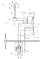
- FIG. 1 is a schematic diagram illustrating an overall configuration of a robot system including a robot arm according to an embodiment of the present invention. It is a partial cross section schematic diagram which shows the principal part structure of the robot arm which concerns on embodiment of this invention.
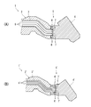
- FIG. 2 is a partial cross-sectional schematic view of a part of a robot arm and an end effector attached to the tip of the robot arm for explaining a problem that may occur when the robot arm is downsized.
- FIG. 1 is a schematic diagram illustrating an overall configuration of a robot system including a robot arm according to the present embodiment.
- the robot system 10 supplies a protective gas into a robot 20 that performs a painting operation in a first region where an explosive atmosphere exists, and a container that defines the peripheral edge of the internal pressure explosion-proof structure of the robot 20.
- a scavenging device 70 for scavenging and a control device 90 for controlling the robot 20 and the scavenging device 70 are provided.
- the robot system 10 further includes a partition unit 98 for partitioning the first region where the explosive atmosphere exists and the second region where the explosive atmosphere does not exist.
- a flow rate adjusting device 76, a base 21, a robot arm 30, and an end effector 50, which will be described later, are installed in the first region. Further, a protective gas supply source 71 and a control device 90 described later are installed in the second region.
- the robot 20 is configured as a painting robot for painting an automobile or the like. Therefore, in this embodiment, the said 1st area
- the atmosphere of the paint shop is a combustible gas (or explosive gas) by mixing the gas containing the organic solvent contained in the paint. If an electric device is used without taking any measures in such a first region, an explosion occurs due to a spark generated by energization.
- the robot 20 is provided with many electric devices such as a servo motor (not shown) in a container that defines a part of the periphery of the robot 20. Therefore, before energizing the robot 20, it is necessary to remove the combustible gas that has entered the container. Therefore, by using the scavenging device 70, scavenging is performed by supplying a protective gas into the container.
- a servo motor not shown
- the base 21 and a part of the robot arm 30 constitute the container. Specifically, the internal space of the base 21 and the internal space of the robot arm 30 communicate with each other, and the internal space of the robot arm 30 extends from the base end portion of the robot arm 30 to the portion of the third joint axis JT3. ing.
- the robot 20 performs a painting operation by controlling the base 21, the robot arm 30 connected to the base 21, the end effector 50 attached to the tip of the robot arm 30, and the robot arm 30 and the end effector 50. And a robot control device 60.
- the robot arm 30 has seven joint axes JT1 to JT7 and six links 31a to 31f sequentially connected by these joint axes.
- Each of the joint axes JT1 to JT7 of the robot arm 30 is rotatably provided by a servo motor.
- the first joint shaft JT1 is connected by a servo motor so that the distal end portion of the first link 31a and the proximal end portion of the second link 31b are rotatable about an axis extending in the vertical direction.
- the second joint axis JT2 is driven by a servo motor on the plane where the front-rear direction and the vertical direction of the robot 20 intersect the distal end portion of the second link 31b and the proximal end portion of the third link 31c around the axis extending in the horizontal direction. It is connected so that it can rotate.
- the third joint axis JT3 is driven by a servo motor on the plane where the front-rear direction and the vertical direction of the robot 20 intersect the distal end portion of the third link 31c and the proximal end portion of the fourth link 31d around the axis extending in the horizontal direction. It is connected so that it can rotate.
- the fourth joint shaft JT4 connects the distal end portion of the fourth link and the proximal end portion of the fifth link 31e so as to be twisted and rotated by a servo motor.
- the fifth joint shaft JT5 connects the distal end portion of the fifth link 31e and the proximal end portion of the sixth link 31f so as to be twisted and rotated by a servo motor.
- the sixth joint shaft JT6 connects the distal end portion of the sixth link 31f and the proximal end portion of the end effector 50 in a twistable manner by a servo motor.
- the seventh joint axis JT7 can be rotated by the servo motor between the base 21 and the base end portion of the first link 31a on a plane where the horizontal direction and the vertical direction of the robot 20 intersect about the axis extending in the horizontal direction. Link.
- Servo motors for rotating the first to third joint axes JT1 to JT3 and the seventh joint axis JT7 are respectively connected to the joint axes to be rotated by themselves.
- the servo motors for rotating the fourth to sixth joint axes JT4 to JT6 are provided separately from the joint axes to be rotated by themselves.
- the servo motors are provided adjacent to each other in the vicinity of the third joint axis JT3, and rotate the joint axes that are separated from each other via wiring.
- Servo motors for rotating the first to seventh joint shafts JT1 to JT7 are respectively provided in the containers.
- the end effector 50 is configured as a coating gun for spraying paint supplied from a paint supply hose (piping) included in a plurality of long members 32 to be described later onto a vehicle body or the like.
- the painting gun is configured as a bell type painting gun.
- the robot control device 60 is provided in the control device 90 together with the scavenging control device 80.
- the specific configuration of the robot control device 60 is not particularly limited. For example, a configuration realized by a known processor (CPU or the like) operating according to a program stored in a storage unit (memory) may be used.
- the scavenging device 70 includes a protective gas supply source 71, a supply flow path 72 (flow path) for guiding the protective gas from the protective gas supply source 71 into the container, and protection supplied from the protective gas supply source 71 into the container.
- a flow rate adjusting device 76 for adjusting the flow rate of gas and a scavenging control device 80 for controlling the flow rate adjusting device 76 to perform scavenging are provided.
- the protective gas supply source 71 is provided in the second region.
- scavenging may be performed using air as the protective gas.
- the supply flow path 72 extends from the protective gas supply source 71 provided in the second region to the inside of the container of the robot 20 provided in the first region. Specifically, the supply flow path 72 is inserted into the container through a through hole formed in the base 21 of the robot 20, and the deepest part in the container (that is, a portion of the third joint axis JT3). ) And a protective gas is supplied from the tip.
- the supply flow path 72 further has a branch path extending to a servo motor that rotates the second joint shaft JT2, and a protective gas is supplied from the front end thereof. Further, the supply flow path 72 further has a branch path extending to the vicinity of the servo motor that rotates the seventh joint shaft JT7, and the protective gas is also supplied from the tip portion thereof.
- discharge flow path 74 The protective gas supplied into the container is discharged from the container by the discharge channel 74.
- the discharge channel 74 extends to the outside of the container through a through hole formed in the base 21. Since the pressure in the container is higher than the atmospheric pressure, the protective gas supplied from the supply flow path 72 into the container is discharged to the outside of the container so as to be sucked into the tip of the discharge flow path 74.
- the flow rate adjusting device 76 has a first control valve 77 provided on the supply flow path 72 and a second control valve 78 provided on the discharge flow path 74.
- the scavenging control device 80 is provided in the control device 90 together with the robot control device 60.
- the specific configuration of the scavenging control device 80 is not particularly limited.
- a known processor CPU or the like
- a storage unit memory
- FIG. 2 is a partial cross-sectional schematic view showing the main configuration of the robot arm according to the present embodiment.
- the robot arm 30 according to the present embodiment defines a plurality of elongated members 32 extending to the end effector 50 and a peripheral edge of an internal space 34 that serves as a passage for the plurality of elongated members 32.
- a cylindrical housing 36 A cylindrical housing 36.
- the robot arm 30 further includes an attachment structure 40 provided to the tip of the internal space 34 of the cylindrical housing 36 in order to attach the end effector 50 to the tip of the cylindrical housing 36.
- a plurality of fixing members 42 described later are arranged in the internal space 34.
- Each of the plurality of long members 32 is configured as a wiring or a pipe.
- the plurality of elongate members 32 have electrical wiring (wiring) connected to the end effector 50 and paint supply hose (piping).
- Each of the plurality of long members 32 may be formed with a smaller diameter than a similar member provided in a robot arm that is not downsized. Thereby, it becomes easy to reduce the size of the robot arm.
- the fourth armature axis JT4 to the tip of the robot arm 30 constitutes a cylindrical housing 36.
- the plurality of elongated members 32 may be arranged so as to be exposed along the outer surface of the robot arm 30 on the proximal end side with respect to the fourth joint axis JT4. Thereby, the maintainability etc. of the some elongate member 32 can be improved.
- the cylindrical housing 36 is formed such that the inner diameter of the distal end portion is larger than the inner diameter of the proximal end portion.
- the cylindrical housing 36 has a sixth joint axis JT6 (joint axis provided on the most distal side among the plurality of joint axes) and a fifth joint axis JT5 (one of them) in the axial direction.
- An inner diameter expansion portion 37 having an inner diameter that increases toward the distal end portion is provided between the joint shaft and the joint shaft provided on the end side.
- the cylindrical housing 36 may have a constant inner diameter at the base end portion (that is, a portion closer to the base end side than the inner diameter expansion portion 37) in the axial direction.
- the inner diameter may be about 50 cm, for example.
- the cylindrical housing 36 may have a constant inner diameter at the distal end portion (that is, the portion on the distal end side with respect to the inner diameter expanding portion 37) in the axial direction.
- the inner diameter may be about 70 cm, for example.
- the attachment structure 40 includes an insertion hole 44 formed corresponding to each of the plurality of long members 32 in order to insert each of the plurality of long members 32, and each of the plurality of long members 32. And a fixing member 42 for fixing to the insertion hole 44.
- the fixing member 42 may be, for example, a hexagonal nut attached so as to surround the plurality of long members 32 from the end effector 50 side. That is, the radial dimension of the fixing member 42 is larger than the radial dimension of the plurality of long members 32 when viewed in the axial direction of the cylindrical housing 36.
- FIG. 3 is a schematic view of a part of the robot arm and an end effector attached to the tip of the robot arm for explaining problems that may occur when the robot arm is downsized.
- A shows a schematic diagram of a robot arm according to the conventional first aspect and an end effector attached to the tip thereof
- (B) shows a robot arm according to the conventional second aspect and attached to the tip thereof.
- Fig. 3 shows a schematic diagram of an end effector.
- an attachment structure 5 for attaching the end effector 4 is provided at the tip of the robot arm 1 according to the conventional first aspect.
- the attachment structure 5 includes an insertion hole 7 drilled corresponding to each of the plurality of long members 8 in order to insert each of the plurality of long members 8, and each of the plurality of long members 8. And a fixing member 6 for fixing to the insertion hole 7.
- the robot arm 1 ' As shown in FIG. 3 (B), the robot arm 1 'according to the second aspect of the prior art has a cylindrical housing 2' and an internal space 3 formed small.
- the mounting structure 5 ′ since it is difficult for the mounting structure 5 ′ to reduce the diameter of the fixing member 6 ′, it is difficult to reduce the size of the main structure.
- the mounting structure 5 included in the first conventional aspect the plurality of long members 8 ′ each reach the insertion hole 7 ′ of the mounting structure 5 ′ from the internal space of the cylindrical housing 2 ′. By the time, it will be bent rapidly toward the outer side in the radial direction of the cylindrical casing 2 ′. By bending in this way, each of the plurality of long members 8 ′ is damaged.
- a spacer is provided between the cylindrical housing 2 ′ and the mounting structure 5 ′, and each of the plurality of long members 8 ′ is gently bent in the spacer. It can be considered that the damage to the plurality of long members 8 ′ is suppressed by reaching the mounting structure 5 ′ from the top.
- providing the spacer in this way is contrary to the purpose of reducing the size of the robot arm 1 '.
- the robot arm 30 according to the present embodiment is formed such that the inner diameter of the distal end portion is larger than the inner diameter of the proximal end portion.
- each of the plurality of long members 32 is abruptly directed outwardly in the radial direction of the cylindrical casing 36 from the internal space 34 of the cylindrical casing 36 to the insertion hole 44 of the mounting structure 40. There is no bending.
- the inner diameter is small at a place other than the tip, the size can be reduced. As a result, the robot arm 30 according to the present invention can suppress damage to the plurality of long members 32 inserted therein while reducing the size.
- the cylindrical housing 36 includes the inner diameter expansion portion 37 whose inner diameter increases toward the distal end portion between the distal end portion and the proximal end portion.
- a plurality of elongated members 32 can be gently bent inside 36. Thereby, it can suppress further that the some elongate member 32 will be damaged.
- the cylindrical housing 36 has the inner diameter expansion portion 37 between the sixth joint axis JT6 and the fifth joint axis JT5 in the axial direction thereof, so that it is as small as possible. It is possible to suppress damage to the plurality of long members 32 while achieving the reduction.
- the robot arm 30 which concerns on this embodiment has the said effect, by extension, the robot 20 provided with it suppresses the damage of the some elongate member 32 penetrated inside, aiming at size reduction. Is possible.
- the robot 20 is configured as a painting robot.
- the present invention is not limited to this.
- the robot 20 may be configured as a transfer robot for transferring a workpiece, or may be configured as another robot.
- the end effector 50 is configured as a bell-type paint gun.
- the present invention is not limited to this.
- the end effector 50 may be a simple spray paint gun, or may be another paint gun.
- the end effector 50 is configured as an end effector other than the coating gun (for example, an end effector having a holding unit for holding a workpiece). May be.
- the present invention is not limited thereto.
- all of the plurality of elongated members 32 may be electric wirings, or all of them may be paint supply hoses.
- a long member that is not inserted into the internal space 34 of the cylindrical housing 36 may be exposed to the outside of the cylindrical housing 36 and extend to the end effector 50.
- the plurality of long members 32 may have piping other than the paint supply hose.
- the present invention is not limited to this case. , May be provided at other locations.
- the cylindrical housing 36 may be formed so that the diameter dimension increases from the proximal end to the distal end over the entire region from the axial proximal end to the distal end. In other words, the entire cylindrical housing 36 may be configured as the inner diameter expansion portion 37.
- the inner diameter expansion portion 37 has a linear inner surface when viewed from the side, but may have a stepped shape or other shapes. It may be. Note that the inner diameter expansion portion 37 may have a structure in which the inner diameter is intermittently increased toward the distal end portion of the cylindrical housing 36 by forming one or more concave portions on the inner surface.
- the inner diameter expansion portion 37 is not limited to an aspect in which the inner diameter increases toward the distal end portion of the cylindrical casing 36, and has a structure in which the inner diameter increases at one place in the axial direction of the cylindrical casing 36. May be.
Landscapes
- Engineering & Computer Science (AREA)
- Robotics (AREA)
- Mechanical Engineering (AREA)
- Manipulator (AREA)
Abstract
Priority Applications (5)
| Application Number | Priority Date | Filing Date | Title |
|---|---|---|---|
| KR1020237002746A KR20230021151A (ko) | 2018-05-31 | 2019-05-30 | 로봇 암 및 이를 구비한 로봇 |
| CN201980034879.2A CN112166014B (zh) | 2018-05-31 | 2019-05-30 | 机器人臂及具备其的机器人 |
| US17/059,541 US11745357B2 (en) | 2018-05-31 | 2019-05-30 | Robotic arm and robot having the same |
| KR1020207035970A KR20210010531A (ko) | 2018-05-31 | 2019-05-30 | 로봇 암 및 이를 구비한 로봇 |
| EP19811240.1A EP3804921B1 (fr) | 2018-05-31 | 2019-05-30 | Bras robotisé et robot pourvu de celui-ci |
Applications Claiming Priority (2)
| Application Number | Priority Date | Filing Date | Title |
|---|---|---|---|
| JP2018104976A JP7121546B2 (ja) | 2018-05-31 | 2018-05-31 | ロボットアーム及びそれを備えるロボット |
| JP2018-104976 | 2018-05-31 |
Publications (1)
| Publication Number | Publication Date |
|---|---|
| WO2019230896A1 true WO2019230896A1 (fr) | 2019-12-05 |
Family
ID=68697564
Family Applications (1)
| Application Number | Title | Priority Date | Filing Date |
|---|---|---|---|
| PCT/JP2019/021561 Ceased WO2019230896A1 (fr) | 2018-05-31 | 2019-05-30 | Bras robotisé et robot pourvu de celui-ci |
Country Status (6)
| Country | Link |
|---|---|
| US (1) | US11745357B2 (fr) |
| EP (1) | EP3804921B1 (fr) |
| JP (1) | JP7121546B2 (fr) |
| KR (2) | KR20210010531A (fr) |
| CN (1) | CN112166014B (fr) |
| WO (1) | WO2019230896A1 (fr) |
Families Citing this family (3)
| Publication number | Priority date | Publication date | Assignee | Title |
|---|---|---|---|---|
| JP7504011B2 (ja) * | 2020-12-09 | 2024-06-21 | 株式会社安川電機 | ロボットシステム |
| DE102022100608A1 (de) | 2022-01-12 | 2023-07-13 | Dürr Systems Ag | Roboterhand, insbesondere zum Tragen einer Applikationsvorrichtung |
| CN118237200A (zh) * | 2024-05-24 | 2024-06-25 | 山西喆星安全技术开发有限公司 | 移动式喷涂机器人及货运列车侧门缝隙补漏方法 |
Citations (7)
| Publication number | Priority date | Publication date | Assignee | Title |
|---|---|---|---|---|
| JP2000158377A (ja) * | 1998-11-30 | 2000-06-13 | Tokico Ltd | 塗装用ロボット |
| JP2002079487A (ja) * | 2000-09-05 | 2002-03-19 | Nachi Fujikoshi Corp | 産業用ロボットの手首装置 |
| JP2005096073A (ja) * | 2001-10-22 | 2005-04-14 | Yaskawa Electric Corp | 産業用ロボット |
| JP2005279635A (ja) * | 2004-03-03 | 2005-10-13 | Toyota Motor Corp | 塗装ロボット用静電塗装機 |
| US20060104792A1 (en) * | 2001-08-16 | 2006-05-18 | Stefano Giuliano | Manipulator with a line arrangement leading to the processing tool |
| JP2015016523A (ja) | 2013-07-10 | 2015-01-29 | ファナック株式会社 | 産業用ロボットの手首構造部 |
| JP2017507799A (ja) * | 2014-03-18 | 2017-03-23 | デュール システムズ アーゲーDurr Systems AG | ロボット組立品と対応する組立方法 |
Family Cites Families (3)
| Publication number | Priority date | Publication date | Assignee | Title |
|---|---|---|---|---|
| EP1491299A1 (fr) | 2003-06-26 | 2004-12-29 | Abb Ab | Articulation de poignet robotique composée de plusieurs éléments en série entrainés par des engrenages coniques |
| US20050194474A1 (en) * | 2004-03-03 | 2005-09-08 | Ransburg Industrial Finishing K.K. | Electrostatic atomizer for a painting robot |
| JP6184161B2 (ja) * | 2012-07-12 | 2017-08-23 | キヤノン株式会社 | ロボット |
-
2018
- 2018-05-31 JP JP2018104976A patent/JP7121546B2/ja active Active
-
2019
- 2019-05-30 KR KR1020207035970A patent/KR20210010531A/ko not_active Ceased
- 2019-05-30 WO PCT/JP2019/021561 patent/WO2019230896A1/fr not_active Ceased
- 2019-05-30 US US17/059,541 patent/US11745357B2/en active Active
- 2019-05-30 KR KR1020237002746A patent/KR20230021151A/ko not_active Ceased
- 2019-05-30 EP EP19811240.1A patent/EP3804921B1/fr active Active
- 2019-05-30 CN CN201980034879.2A patent/CN112166014B/zh active Active
Patent Citations (7)
| Publication number | Priority date | Publication date | Assignee | Title |
|---|---|---|---|---|
| JP2000158377A (ja) * | 1998-11-30 | 2000-06-13 | Tokico Ltd | 塗装用ロボット |
| JP2002079487A (ja) * | 2000-09-05 | 2002-03-19 | Nachi Fujikoshi Corp | 産業用ロボットの手首装置 |
| US20060104792A1 (en) * | 2001-08-16 | 2006-05-18 | Stefano Giuliano | Manipulator with a line arrangement leading to the processing tool |
| JP2005096073A (ja) * | 2001-10-22 | 2005-04-14 | Yaskawa Electric Corp | 産業用ロボット |
| JP2005279635A (ja) * | 2004-03-03 | 2005-10-13 | Toyota Motor Corp | 塗装ロボット用静電塗装機 |
| JP2015016523A (ja) | 2013-07-10 | 2015-01-29 | ファナック株式会社 | 産業用ロボットの手首構造部 |
| JP2017507799A (ja) * | 2014-03-18 | 2017-03-23 | デュール システムズ アーゲーDurr Systems AG | ロボット組立品と対応する組立方法 |
Non-Patent Citations (1)
| Title |
|---|
| See also references of EP3804921A4 |
Also Published As
| Publication number | Publication date |
|---|---|
| EP3804921A1 (fr) | 2021-04-14 |
| CN112166014B (zh) | 2023-11-14 |
| JP2019209396A (ja) | 2019-12-12 |
| US20210206000A1 (en) | 2021-07-08 |
| JP7121546B2 (ja) | 2022-08-18 |
| CN112166014A (zh) | 2021-01-01 |
| EP3804921A4 (fr) | 2022-03-30 |
| KR20210010531A (ko) | 2021-01-27 |
| US11745357B2 (en) | 2023-09-05 |
| EP3804921B1 (fr) | 2025-11-05 |
| KR20230021151A (ko) | 2023-02-13 |
Similar Documents
| Publication | Publication Date | Title |
|---|---|---|
| EP2006056B1 (fr) | Robot industriel avec un câble ombilical et un câble plat disposés le long d'un élément d'articulation de poignet | |
| WO2019230896A1 (fr) | Bras robotisé et robot pourvu de celui-ci | |
| JP6245096B2 (ja) | ロボットおよびロボットシステム | |
| JP3987845B2 (ja) | 産業用ロボットの線条体処理構造 | |
| CN101272886B (zh) | 多关节机械手、机器人系统以及双臂多关节机械手 | |
| US9346174B2 (en) | Umbilical member arrangement structure of industrial robot having hollow member | |
| JP4038217B2 (ja) | 産業用ロボットの線条体処理構造 | |
| JP2015027714A (ja) | ロボット | |
| CN102463571A (zh) | 机器人手腕结构和机器人 | |
| US20160023360A1 (en) | Robot | |
| US11141869B2 (en) | Robot-arm harness connection structure and multi-joined welding robot | |
| US11541556B2 (en) | Robot wrist structure | |
| JP4822061B2 (ja) | 双腕ロボット | |
| US20160023359A1 (en) | Robot joint mechanism and robot | |
| CN107538477A (zh) | 机器人、控制装置及机器人系统 | |
| CN103889666A (zh) | 多轴机械手 | |
| JP4817132B2 (ja) | 内圧防爆構造のロボットおよびそれを備えた内圧防爆システム | |
| JP2021516028A5 (fr) | ||
| WO2021005968A1 (fr) | Robot industriel suspendu | |
| JP2018164959A (ja) | ロボット装置 | |
| CN201482642U (zh) | 喷涂系统 | |
| US20170210016A1 (en) | Robot | |
| JP5135925B2 (ja) | ロボット | |
| EP3002091A1 (fr) | Robot | |
| JP2003025270A (ja) | 産業用ロボットの配線配管処理装置 |
Legal Events
| Date | Code | Title | Description |
|---|---|---|---|
| 121 | Ep: the epo has been informed by wipo that ep was designated in this application |
Ref document number: 19811240 Country of ref document: EP Kind code of ref document: A1 |
|
| NENP | Non-entry into the national phase |
Ref country code: DE |
|
| ENP | Entry into the national phase |
Ref document number: 20207035970 Country of ref document: KR Kind code of ref document: A |
|
| ENP | Entry into the national phase |
Ref document number: 2019811240 Country of ref document: EP Effective date: 20210111 |
|
| WWG | Wipo information: grant in national office |
Ref document number: 2019811240 Country of ref document: EP |