WO2019234867A1 - Plaque bipolaire, cadre de cellule, empilement de cellules et batterie à flux redox - Google Patents
Plaque bipolaire, cadre de cellule, empilement de cellules et batterie à flux redox Download PDFInfo
- Publication number
- WO2019234867A1 WO2019234867A1 PCT/JP2018/021776 JP2018021776W WO2019234867A1 WO 2019234867 A1 WO2019234867 A1 WO 2019234867A1 JP 2018021776 W JP2018021776 W JP 2018021776W WO 2019234867 A1 WO2019234867 A1 WO 2019234867A1
- Authority
- WO
- WIPO (PCT)
- Prior art keywords
- bipolar plate
- groove
- electrode
- cell
- introduction
- Prior art date
- Legal status (The legal status is an assumption and is not a legal conclusion. Google has not performed a legal analysis and makes no representation as to the accuracy of the status listed.)
- Ceased
Links
Images





Classifications
-
- H—ELECTRICITY
- H01—ELECTRIC ELEMENTS
- H01M—PROCESSES OR MEANS, e.g. BATTERIES, FOR THE DIRECT CONVERSION OF CHEMICAL ENERGY INTO ELECTRICAL ENERGY
- H01M8/00—Fuel cells; Manufacture thereof
- H01M8/02—Details
- H01M8/0202—Collectors; Separators, e.g. bipolar separators; Interconnectors
- H01M8/0258—Collectors; Separators, e.g. bipolar separators; Interconnectors characterised by the configuration of channels, e.g. by the flow field of the reactant or coolant
-
- H—ELECTRICITY
- H01—ELECTRIC ELEMENTS
- H01M—PROCESSES OR MEANS, e.g. BATTERIES, FOR THE DIRECT CONVERSION OF CHEMICAL ENERGY INTO ELECTRICAL ENERGY
- H01M8/00—Fuel cells; Manufacture thereof
- H01M8/18—Regenerative fuel cells, e.g. redox flow batteries or secondary fuel cells
-
- Y—GENERAL TAGGING OF NEW TECHNOLOGICAL DEVELOPMENTS; GENERAL TAGGING OF CROSS-SECTIONAL TECHNOLOGIES SPANNING OVER SEVERAL SECTIONS OF THE IPC; TECHNICAL SUBJECTS COVERED BY FORMER USPC CROSS-REFERENCE ART COLLECTIONS [XRACs] AND DIGESTS
- Y02—TECHNOLOGIES OR APPLICATIONS FOR MITIGATION OR ADAPTATION AGAINST CLIMATE CHANGE
- Y02E—REDUCTION OF GREENHOUSE GAS [GHG] EMISSIONS, RELATED TO ENERGY GENERATION, TRANSMISSION OR DISTRIBUTION
- Y02E60/00—Enabling technologies; Technologies with a potential or indirect contribution to GHG emissions mitigation
- Y02E60/30—Hydrogen technology
- Y02E60/50—Fuel cells
Definitions
- the present invention relates to a bipolar plate, a cell frame, a cell stack, and a redox flow battery.
- a redox flow battery (hereinafter sometimes referred to as “RF battery”) is known (see, for example, Patent Documents 1 and 2).
- RF battery uses a cell stack in which a plurality of cell frames, positive electrodes, diaphragms, and negative electrodes are stacked.
- the cell frame includes a bipolar plate disposed between the positive electrode and the negative electrode, and a frame provided on the outer periphery of the bipolar plate.
- positive and negative electrodes are arranged between bipolar plates of adjacent cell frames with a diaphragm interposed therebetween to form one cell.
- the RF battery performs charging / discharging by circulating an electrolyte solution in a cell containing an electrode by a pump.
- Patent Documents 1 and 2 describe that a channel is formed by forming a plurality of grooves through which an electrolytic solution flows on the electrode side surface of a bipolar plate.
- the bipolar plate of the present disclosure is An electrode of a redox flow battery is disposed, and is a bipolar plate provided with a facing surface facing the electrode, and at least one groove constituting a flow path through which an electrolyte flows in the facing surface, When the bipolar plate is viewed in plan, at least one of the grooves has a curved portion.
- the cell frame of the present disclosure is The bipolar plate of the present disclosure and a frame body provided on the outer periphery of the bipolar plate.
- the cell stack of the present disclosure is The cell frame of the present disclosure is provided.
- the redox flow battery of the present disclosure is The cell stack of the present disclosure is provided.
- FIG. 5 is an enlarged view showing one of the grooves constituting the flow path of the electrolytic solution shown in FIG. 4. It is a schematic sectional drawing which shows typically the cross-sectional shape of the groove
- Sample No. used in Test Example 1 It is a top view which shows 1 bipolar plate. Sample No. used in Test Example 1 It is a top view which shows 2 bipolar plates. Sample No. used in Test Example 1 3 is a plan view showing a bipolar plate 3.
- the electrode of the redox flow battery functions as a reaction field that promotes the battery reaction of the active material (metal ions) contained in the supplied electrolyte.
- a porous material such as carbon felt made of carbon fiber is usually used for the electrode, and an electrolytic solution flows in the electrode.
- a flow path having a groove through which the electrolytic solution flows is provided on the electrode side surface of the bipolar plate, the flow resistance of the electrolytic solution can be reduced, and the pressure loss due to the flow resistance of the electrolytic solution can be reduced.
- a bipolar plate having a channel having a groove the flow of the electrolyte solution penetrating into the electrode can be controlled, and the distribution of the electrolyte solution in the electrode can be suppressed from becoming non-uniform. By suppressing variations in the distribution of the electrolyte solution penetrating into the electrode, the reactivity between the electrode and the electrolyte solution can be improved, and the reaction resistance at the electrode can be reduced.
- the bipolar plate according to the embodiment is An electrode of a redox flow battery is disposed, and is a bipolar plate provided with a facing surface facing the electrode, and at least one groove constituting a flow path through which an electrolyte flows in the facing surface, When the bipolar plate is viewed in plan, at least one of the grooves has a curved portion.
- the flow path of the electrolytic solution is formed on the facing surface facing the electrode, so that the flow resistance of the electrolytic solution can be reduced and the distribution of the electrolytic solution penetrating into the electrode can be controlled. Since at least one groove constituting the flow path has a curved portion, the degree of freedom in layout is increased compared to a straight groove, so that the groove can be efficiently formed so that the distribution of the electrolyte in the electrode is uniform. It is possible to arrange. Thereby, the uniformity of the distribution of the electrolytic solution in the electrode can be sufficiently increased, and the reactivity between the electrode and the electrolytic solution can be improved. Therefore, the bipolar plate can improve the reactivity between the electrode and the electrolytic solution while reducing the flow resistance of the electrolytic solution. Therefore, when the bipolar plate is used in a redox flow battery, the reaction resistance at the electrode can be reduced while the pressure loss due to the flow resistance of the electrolyte can be reduced, so the internal resistance of the battery (cell resistance) Can be reduced.
- the “curved part” of the groove refers to a curved part in the longitudinal direction of the groove.
- the curved portion is typically a non-periodic curved shape.
- the curvature radius of the curved portion is 0.1 mm or more.
- the groove having the curved portion can be easily formed.
- the upper limit of the curvature radius of the curved portion is not particularly limited, but is, for example, 100 mm or less.
- the pressure of the electrolyte increases as it approaches the tip, and the electrolyte can easily penetrate from the groove into the electrode.
- a / (A + B) is more than 0.5 and less than 0.95, where A is the contact area in contact with the electrode and B is the planar opening area of the groove. Can be mentioned.
- the ratio [A / (A + B)] of the contact area (A) of the electrode to the area (A + B) of the opposite surface of the bipolar plate is more than 0.5, the contact area between the electrode and the bipolar plate is secured.
- the contact resistance between the electrode and the bipolar plate can be reduced.
- the internal resistance (cell resistance) of the battery can be reduced.
- the ratio [A / (A + B)] of the electrode contact area is preferably less than 0.95. Thereby, the distribution
- the “planar opening area” of the groove means the opening area of the groove on the opposite surface when the bipolar plate is viewed in plan.
- the width on the opening side of the groove is equal to or larger than the width on the bottom side.
- the cross-sectional shape of the groove is formed in a tapered shape from the opening side toward the bottom side.
- the cross section of the groove is formed in a tapered shape from the opening side to the bottom side, the electrolyte can easily penetrate from the groove into the electrode.
- the groove is formed in a dendritic shape, and includes a trunk groove part and at least one branch groove part branched from the trunk groove part, It is mentioned that at least one of the branch groove portions intersects the trunk groove portion non-orthogonally.
- the groove is formed in a dendritic shape, it is easy to permeate and diffuse the electrolytic solution from the groove over a wide range in the electrode, and the distribution of the electrolytic solution in the electrode can be made more uniform. Therefore, the reactivity between the electrode and the electrolytic solution can be further improved. Further, the branch groove portion branched from the trunk groove portion intersects the trunk groove portion in a non-orthogonal direction, so that the flow resistance of the electrolytic solution can be reduced as compared with the case where the branch groove portion is orthogonal to the trunk groove portion.
- branch groove portions has a branch groove portion that further branches from the branch groove portion.
- N natural number
- the groove width (opening width) of the branched branch groove part is reduced and narrowed.
- N the number of branches of the branch groove portion
- the number of branching means the number of times the branching part branches from the trunk part. When there is a branch groove part (primary branch groove) branched from the trunk groove part, the branching number is set to 1. When there is a branch groove part (secondary branch groove) further branched from the branch groove part, the branching number is set to 2. And count. When there is a branch groove portion (third branch groove) that further branches from the secondary branch groove, the number of branches is counted as three.
- the “N” is a natural number (1, 2, 3,).
- the contact width between the electrode and the bipolar plate can be increased and the contact resistance between the electrode and the bipolar plate can be reduced by decreasing the opening width of the branched branch groove portion step by step each time it branches.
- the flow path is An inlet and an outlet for the electrolyte;
- the introduction path and the discharge path each include at least one groove; It is mentioned that at least one of the introduction path and the discharge path includes a rectification unit that is connected to the introduction port or the discharge port and is formed along an edge of the bipolar plate.
- the electrolyte flows so as to cross between the introduction path and the discharge path. At that time, the electrolyte penetrates and diffuses into the electrode, and the electrolyte The entire electrode can be evenly distributed. As a result, the distribution of the electrolytic solution in the electrode can be made more effective and uniform, and the reactivity between the electrode and the electrolytic solution can be further improved. Further, by providing the rectifying unit, it is possible to efficiently introduce or discharge the electrolytic solution from the introduction port or the discharge port with respect to at least one of the introduction path and the discharge path.
- the effective electrode region where the bipolar plate and the electrode face each other is rectangular, and the introduction port and the discharge port are provided at diagonal positions of the effective electrode region, An angle formed by the rectifying unit and a diagonal line of the effective electrode region is 40 ° or more and 50 ° or less.
- the pressure loss in the rectification unit can be reduced by the angle between the rectification unit and the diagonal of the effective electrode region being 40 ° or more and 50 ° or less.
- the bipolar plate As one form of the bipolar plate, it can be mentioned that at least a part of the groove has a wide part having an opening width of 2 mm or more, and a convex part protruding from the bottom part is formed in the wide part.
- the cell frame according to the embodiment is The bipolar plate according to any one of (1) to (16) above and a frame body provided on the outer periphery of the bipolar plate.
- the cell frame includes the bipolar plate according to the above-described embodiment, the reactivity between the electrode and the electrolytic solution can be improved while reducing the flow resistance of the electrolytic solution. While being able to reduce, it is possible to reduce the reaction resistance at the electrode. Therefore, when the cell frame is used for a redox flow battery, the internal resistance (cell resistance) of the battery can be reduced, and the battery performance can be improved.
- the cell stack according to the embodiment is The cell frame according to (17) is provided.
- the cell stack includes the cell frame according to the above-described embodiment, so that the reaction resistance at the electrode can be reduced while the pressure loss due to the flow resistance of the electrolytic solution can be reduced. Therefore, when the cell stack is used for a redox flow battery, the internal resistance (cell resistance) of the battery can be reduced, and the battery performance can be improved.
- the redox flow battery according to the embodiment is The cell stack according to (18) is provided.
- the redox flow battery includes the cell stack according to the above-described embodiment, it is possible to reduce the reaction loss at the electrode while reducing the pressure loss due to the flow resistance of the electrolytic solution. Resistance (cell resistance) can be reduced. Therefore, the redox flow battery is excellent in battery performance.
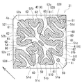
- FIG. 4 is a schematic plan view of the cell frame 3 including the bipolar plate 31 according to the embodiment when viewed from the one surface side of the bipolar plate 31.
- One of the features of the bipolar plate 31 of the embodiment is, as shown in FIG. 4, provided with at least one groove 5 constituting the flow path 4 through which the electrolytic solution flows on the facing surface facing the electrode 14, and the bipolar plate 31.
- at least one of the grooves 5 is at a point having a curved portion.
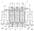
- the RF battery 1 shown in FIG. 1 and FIG. 2 uses an electrolytic solution containing, as an active material, a metal ion whose valence changes as a result of oxidation and reduction in the positive electrode electrolyte and the negative electrode electrolyte.
- the battery performs charging / discharging by utilizing the difference between the redox potential and the redox potential of ions contained in the negative electrode electrolyte.
- a vanadium-based RF battery using a vanadium electrolyte solution containing V ions in the positive electrode electrolyte and the negative electrode electrolyte is shown.
- a solid line arrow in the cell 10 in FIG. 1 indicates a charging reaction, and a broken line arrow indicates a discharging reaction.
- the RF battery 1 is connected to the electric power system P via an AC / DC converter C, for example, for load leveling applications, applications such as sag compensation and emergency power supplies, natural energy power generation such as solar power generation and wind power generation. Used for output smoothing.
- the RF battery 1 includes a cell 10 for charging / discharging, tanks 106 and 107 for storing an electrolyte, and circulation channels 100P and 100N for circulating the electrolyte between the tanks 106 and 107 and the cell 10. .
- the cell 10 includes a positive electrode 14, a negative electrode 15, and a diaphragm 11 interposed between the electrodes 14 and 15.
- the structure of the cell 10 is separated into a positive electrode cell 12 and a negative electrode cell 13 with a diaphragm 11 interposed therebetween, and a positive electrode 14 is incorporated in the positive electrode cell 12 and a negative electrode 15 is incorporated in the negative electrode cell 13.
- Each electrode of the positive electrode 14 and the negative electrode 15 is formed of a carbon fiber aggregate including carbon fibers. Since the electrode of the carbon fiber aggregate is porous and has voids in the electrode, the electrolytic solution flows through the electrode, and the electrolytic solution can permeate and diffuse.
- Examples of the carbon fiber aggregate include carbon felt, carbon cloth, and carbon paper.
- Examples of the carbon fiber include PAN-based carbon fiber using polyacrylonitrile (PAN) fiber as a raw material, pitch-based carbon fiber using pitch fiber as a raw material, and rayon-based carbon fiber using rayon fiber as a raw material.
- the diaphragm 11 is formed of, for example, an ion exchange membrane that transmits hydrogen ions.
- an electrolytic solution (a positive electrode electrolytic solution and a negative electrode electrolytic solution) circulates through the circulation channels 100P and 100N.
- a positive electrode electrolyte tank 106 that stores a positive electrode electrolyte is connected to the positive electrode cell 12 via a positive electrode circulation channel 100P.
- a negative electrode electrolyte tank 107 that stores a negative electrode electrolyte is connected to the negative electrode cell 13 via a negative electrode circulation channel 100N.
- Each circulation flow path 100P, 100N has forward piping 108, 109 for sending the electrolytic solution from each tank 106, 107 to the cell 10 and return piping 110, 111 for returning the electrolytic solution from the cell 10 to each tank 106, 107.
- Pumps 112 and 113 for pumping the electrolytic solution stored in the tanks 106 and 107 are provided in the outgoing pipes 108 and 109, and the electrolytic solution is circulated to the cell 10 by the pumps 112 and 113.
- the cell 10 may be configured as a single cell including a single cell 10 or may be configured as a multi-cell including a plurality of cells 10.
- the cell 10 is normally used in a form called a cell stack 2 including a plurality of stacked cells 10 as shown in FIG.
- the cell stack 2 is configured by sandwiching the sub stack 200 from two end plates 220 from both sides and fastening the end plates 220 on both sides by a fastening mechanism 230.
- FIG. 3 illustrates a cell stack 2 including a plurality of substacks 200.
- a plurality of sub-stacks 200 are stacked in the order of the cell frame 3, the positive electrode 14, the diaphragm 11, and the negative electrode 15 (see the upper diagram of FIG.
- the cell frame 3 includes a bipolar plate 31 disposed between the positive electrode 14 and the negative electrode 15 and a frame body 32 provided around the bipolar plate 31 (see FIG. 3). (See also 4).
- the positive electrode 14 is disposed so as to face the other surface, and on the other surface side of the bipolar plate 31, the negative electrode 15 is disposed so as to face it.
- a bipolar plate 31 is provided inside the frame body 32, and a recess 32 o is formed by the bipolar plate 31 and the frame body 32.
- the recesses 32o are respectively formed on both sides of the bipolar plate 31, and the positive electrode 14 and the negative electrode 15 are accommodated in each recess 32o with the bipolar plate 31 interposed therebetween.
- Each recessed part 32o forms each cell space of the positive electrode cell 12 and the negative electrode cell 13 (refer FIG. 1).
- the planar shape of each of the positive electrode 14 and the negative electrode 15 is not particularly limited, but is rectangular in this embodiment.
- the planar opening shape of the recessed part 32o is the same rectangular shape as an electrode, and the size of the recessed part 32o and an electrode is substantially the same.
- region Effective electrode area
- the bipolar plate 31 is made of, for example, plastic carbon
- the frame body 32 is made of, for example, plastic such as vinyl chloride resin (PVC), polypropylene, polyethylene, fluorine resin, or epoxy resin.
- PVC vinyl chloride resin
- polypropylene polypropylene
- polyethylene polyethylene
- fluorine resin or epoxy resin.
- a frame 32 is integrated around the bipolar plate 31 by injection molding or the like.
- the one surface side and the other surface side of the frame 32 of each adjacent cell frame 3 face each other and face each other, and between the bipolar plates 31 of each adjacent cell frame 3 respectively.
- One cell 10 is formed.
- the electrodes 14 and 15 are accommodated in the recessed portions 32o of the frame body 32 in a compressed state in the thickness direction.
- An annular seal member 37 such as an O-ring or a flat packing is disposed between the frame bodies 32 of each cell frame 3 in order to suppress leakage of the electrolytic solution.
- a seal groove 38 (see FIG. 4) for arranging the seal member 37 is formed in the frame body 32.
- the electrolyte solution in the cell 10 flows through the supply manifolds 33 and 34 and the drainage manifolds 35 and 36 formed through the frame 32 of the cell frame 3 and the supply slits 33 s formed in the frame 32. , 34s and drainage slits 35s, 36s.
- the positive electrode electrolyte is supplied from a liquid supply manifold 33 formed in the lower part of the frame body 32 through a liquid supply slit 33s formed on one surface side of the frame body 32. Are supplied to the positive electrode 14 and discharged to the drainage manifold 35 through the drainage slit 35 s formed in the upper part of the frame 32.
- the negative electrode electrolyte is supplied from the liquid supply manifold 34 formed in the lower part of the frame 32 to the negative electrode 15 through the liquid supply slit 34 s formed on the other surface side of the frame 32, and the frame 32.
- the liquid is discharged to the drainage manifold 36 through the drainage slit 36s formed in the upper part.
- the liquid supply manifolds 33 and 34 and the drainage manifolds 35 and 36 constitute a flow path for the electrolytic solution by stacking the cell frames 3.
- These flow paths communicate with the forward pipes 108 and 109 and the return pipes 110 and 111 of the circulation flow paths 100P and 100N (see FIGS. 1 and 2) via the supply / discharge plate 210 (see the lower figure of FIG. 3), respectively. It is possible to distribute the electrolyte in the cell 10.
- the electrolytic solution is introduced from the lower side of the positive electrode 14 and the negative electrode 15, and the electrolytic solution is discharged from the upper side of the electrodes 14, 15.
- the electrolyte flows from the lower edge of 15 toward the upper edge. 2 and 3, the arrows in the electrodes 14 and 15 indicate the overall flow direction of the electrolytic solution.
- a flow path 4 through which an electrolytic solution flows is formed on the opposing surface of the bipolar plate 31 that faces the electrodes 14 and 15.
- the flow path 4 is constituted by a plurality of grooves 5 (introducing grooves 51a to 51c and discharging grooves 52a to 52c).
- the thick line arrow on the left side of the drawing indicates the overall flow direction of the electrolytic solution.
- FIG. 4 only one surface side of the bipolar plate 31 facing the positive electrode 14 is shown, but the flow path of the electrolytic solution is also provided on the other surface side of the bipolar plate 31 facing the negative electrode 15, similarly to the one surface side. Is formed. Since the structure of the negative electrode electrolyte channel formed on the other surface side of the bipolar plate 31 is the same as that of the positive electrode electrolyte channel 4 shown in FIG.
- the flow path 4 is designed so as to control the distribution of the electrolytic solution penetrating into the electrode 14 and make the distribution of the electrolytic solution in the electrode 14 uniform.
- the flow path 4 includes an inlet 4i and an outlet 4o for electrolyte.
- the introduction port 4i and the discharge port 4o are portions to which the liquid supply slit 33s and the drainage slit 35s are connected, respectively, and the electrolytic solution is introduced from the introduction port 4i through the liquid supply slit 33s, and the liquid discharge slit 35s from the discharge port 4o.
- the electrolyte is discharged.
- the introduction port 4i is positioned at the center of the lower side of the effective electrode region
- the discharge port 4o is positioned at the center of the upper side of the effective electrode region.
- the flow path 4 includes an introduction path 41 for introducing the electrolyte solution from the introduction port 4i and a discharge path 42 for discharging the electrolyte solution to the discharge port 4o.
- the introduction path 41 and the discharge path 42 are independent without communicating with each other.
- the introduction path 41 includes introduction grooves 51a to 51c
- the discharge path 42 includes discharge grooves 52a to 52c.
- the introduction path 41 and the discharge path 42 include rectifying units 510 and 520 connected to the introduction port 4i and the discharge port 4o, respectively.
- the introduction-side rectifier 510 is formed along the lower edge of the bipolar plate 31, and the discharge-side rectifier 520 is formed along the upper edge of the bipolar plate 31.
- the introduction path 41 is connected to the rectification unit 510, and the introduction grooves 51a to 51c communicate with the introduction port 4i via the rectification unit 510.
- the discharge path 42 is connected to the rectification unit 520, and the discharge grooves 52a to 52c communicate with the discharge port 4o via the rectification unit 520.
- the rectifying unit 510 diffuses the electrolyte introduced from the introduction port 4i along the lower edge of the bipolar plate 31, and introduces the electrolyte evenly into the introduction path 41 (introduction grooves 51a to 51c).
- the rectifying unit 520 collects the electrolyte discharged from the discharge path 42 (discharge grooves 52a to 52c) along the upper edge of the bipolar plate 31 to the discharge port 4o.
- the rectifiers 510 and 520 can efficiently introduce and discharge the electrolytic solution from the introduction port 4i and the discharge port 4o to the introduction path 41 and the discharge path 42, respectively.
- the flow path 4 shown in FIG. 4 has a line symmetry (left-right symmetry) with a center line (indicated by a one-dot chain line in the figure) connecting the inlet 4i and the outlet 4o as the axis of symmetry.
- the 4i side (lower side) and the outlet 4o side (upper side) are asymmetric in the vertical direction. Since the flow path 4 is formed asymmetrically between the introduction side and the discharge side, it is possible to improve the flow of the electrolyte solution on the discharge side where the pressure of the electrolyte solution decreases.
- the introduction grooves 51a to 51c constituting the introduction path 41 are connected to the rectification unit 510 on the introduction side, extend from the introduction side (lower side) to the discharge side (upper side), and the distal end side on the discharge side becomes a closed end. Yes.
- the discharge grooves 52a to 52c constituting the discharge path 42 are connected to the discharge-side rectifying unit 520 and extend from the discharge side (upper side) toward the introduction side (lower side), and the leading end side of the introduction side becomes a closed end. Yes.
- Each groove 5 (introduction grooves 51a to 51c and discharge grooves 52a to 52c) is open on the surface of the bipolar plate 31 facing the electrode 14, and as shown in FIG. It is formed so as to become smaller toward.
- the opening width decreases toward the tip side, so that the pressure of the electrolyte increases as it approaches the tip side, and the electrolyte solution easily penetrates into the electrode 14 from the introduction grooves 51a to 51c.
- the “opening width” of the groove 5 refers to a groove width orthogonal to the longitudinal direction of the groove 5.
- the opening width (groove width) and depth (groove depth) of the groove 5 can be appropriately selected according to the size and thickness of the bipolar plate 31 and are not particularly limited.
- the groove width is, for example, from 0.2 mm to 10 mm, further from 0.5 mm to 5 mm, and the groove depth is, for example, from 0.5 mm to 5 mm, further from 1 mm to 3 mm.
- the surface of the bipolar plate 31 is cut with a cutting tool such as an end mill.
- a cutting tool such as an end mill.
- a / (A + B) is preferably more than 0.5 and less than 0.95.
- the ratio [A / (A + B)] of the contact area (A) of the electrode 14 to the area (A + B) of the opposite surface of the bipolar plate 31 is more than 0.5, the contact area between the electrode 14 and the bipolar plate 31 And the contact resistance between the electrode 14 and the bipolar plate 31 can be reduced. Thereby, the internal resistance (cell resistance) of the battery can be reduced. Further, from the viewpoint of securing the formation area of the groove 5 (the flow path area of the electrolytic solution) on the facing surface of the bipolar plate 31, the ratio [A / (A + B)] of the contact area of the electrode 14 is less than 0.95. Is preferable, and the flow resistance of the electrolytic solution can be effectively reduced.
- the ratio [A / (A + B)] of the contact area of the electrode 14 is, for example, 0.6 or more and 0.9 or less, and more preferably 0.7 or more and 0.8 or less.
- the “planar opening area” of the groove 5 refers to the opening area of the groove 5 on the facing surface when the bipolar plate 31 is viewed in plan.
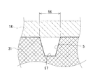
- FIG. 6 shows a cross-sectional shape of the groove 5 in the present embodiment.
- the width of the groove 5 on the opening 56 side is equal to or larger than the width on the bottom 57 side in the cross section orthogonal to the flow direction of the electrolyte in the groove 5.
- the cross-sectional shape is tapered from the opening 56 side toward the bottom 57 side. Therefore, when the width of the groove 56 on the opening 56 side is equal to or larger than the width of the bottom 57 side, the groove 5 is formed compared to the case where the width on the bottom 57 side is wider than the width on the opening 56 side. easy.
- the cross-sectional shape of the groove 5 (particularly, the introduction grooves 51a to 51c) is tapered from the opening 56 side toward the bottom 57 side, the electrolytic solution can easily penetrate from the groove 5 into the electrode.
- the cross-sectional shape of the groove 5 include a rectangular shape, a triangular shape (V shape), a trapezoidal shape, a semicircular shape, and a semielliptical shape.
- the introduction grooves 51 a and 51 c and the discharge grooves 52 a and 52 c are dendritic grooves formed in a dendritic shape. 61. Since at least one of the grooves 5 is formed in a dendritic shape, it is easy to permeate and diffuse the electrolytic solution over a wide range in the electrode 14, and the distribution of the electrolytic solution in the electrode 14 can be made more uniform. . Therefore, the reactivity between the electrode 14 and the electrolytic solution can be further improved.
- the “trunk groove portion” refers to a groove portion that is directly connected to the introduction port 4 i or the discharge port 4 o or indirectly through the rectifying units 510 and 520.
- the “branch groove portion” refers to a groove portion branched from the trunk groove portion 60 and having a smaller opening width than the trunk groove portion 60.
- the branch groove part 61 may have a branch groove part 62 that further branches from the branch groove part 61.
- the branch groove portion 61 is called a primary branch groove
- the branch groove portion 62 is called a secondary branch groove.
- the opening width of the branch groove portion 62 (secondary branch groove) after branching is smaller than the opening width of the branch groove portion 61 (primary branch groove) before branching.
- FIG. 5 shows a drawing of the introduction groove 51c, and the relationship between the trunk groove part 60 and the branch groove part 61, and the branch groove part 61 and the branch groove part 62 will be described by taking the introduction groove 51c as an example.
- the opening width (W a1 ) of the branch groove portion 61 is smaller than the opening width (W a0 ) of the trunk groove portion 60 at a location where the branch groove portion 61 branches from the trunk groove portion 60.
- the opening width (W a2 ) of the branch groove portion 62 is smaller than the opening width (W b1 ) of the branch groove portion 61.
- N is preferably 3 or less, where N (N: natural number) is the number of branches in the branch groove portion.
- the “branching frequency” here means the number of times the branch groove part branches from the trunk groove part. For example, in the introduction groove 51c and the discharge groove 52a, the branching frequency N of the branching groove 61 that branches from the trunk groove 60 is 1, and the branching frequency N of the branching groove 62 that further branches from the branching groove 61 is 2. If there is another branch groove part that further branches from the branch groove part 62, the branching frequency N is three.
- the groove widths (opening widths) of the branched groove portions 61 and 62 are reduced and narrowed.
- the branching frequency N By restricting the branching frequency N to 3 or less as in the present embodiment, excessive narrowing of the groove widths of the branch groove portions 61 and 62 due to branching can be avoided.
- the branch groove part 61 intersects the trunk groove part 60 non-orthogonally.
- the flow resistance of the electrolytic solution can be reduced as compared with the case where the branch groove portion 61 is orthogonal to the trunk groove portion 60.
- “Intersecting non-orthogonally” typically refers to a case where the inclination angle ⁇ (see FIG. 5) in the extending direction of the branch groove portion 61 with respect to the extending direction of the trunk groove portion 60 is an acute angle.
- the inclination angle ⁇ is, for example, not less than 10 ° and not more than 80 °.
- the introduction grooves 51a to 51c of the introduction path 41 and the discharge grooves 52a to 52c of the discharge path 42 have opposing comb tooth regions that are alternately arranged facing each other.
- the branch groove portions 61 of the introduction groove 51a and the branch groove portions 62 of the discharge groove 52a are alternately arranged facing each other, and these also form an opposing comb tooth region.
- the flow path 4 has the opposing comb tooth region, the amount of the electrolyte flowing so as to cross between the introduction path 41 (introduction grooves 51a to 51c) and the discharge path 42 (discharge grooves 52a to 52c) increases.
- the electrolyte solution that permeates and diffuses into the electrode 14 increases. Thereby, the reaction efficiency of the electrode 14 and electrolyte solution can be improved.
- a convex portion 59 protruding from the bottom portion may be formed in the wide portion. Since the convex portion 59 is provided in the wide portion of the groove 5, it is possible to suppress the electrode 14 from being buried in the groove 5.
- the base end sides (sides connected to the rectifying units 510 and 520) of the introduction groove 51a and the discharge groove 52a are partially widened, and the portion Convex part 59 is provided in this.
- the shape of the convex portion 59 when viewed in plan is not particularly limited, and various shapes such as a polygonal shape such as a triangle and a quadrangle, a circular shape, and an elliptical shape can be employed. Further, the number of the convex portions 59 arranged in the wide portion may be one or plural.
- the grooves 5 has a curved portion.
- the “curved portion” refers to a portion that is curved in the longitudinal direction of the groove 5, and is typically a non-periodic curved shape.
- the branch groove portions 61 and 62 of the introduction groove 51c and the branch groove portions 61 and 62 of the discharge groove 52a are formed in a curved shape, and each is constituted by a curved portion.
- the curvature radius of the curved portion is, for example, 0.1 mm or more, further 1 mm or more, and further 3 mm or more.
- the flow path 4 of the electrolytic solution is formed on the opposing surface facing the electrode 14, so that the flow resistance of the electrolytic solution can be reduced and the electrolysis that penetrates into the electrode 14.
- the liquid distribution can be controlled. Since at least one groove 5 constituting the flow path 4 has a curved portion, the degree of freedom in layout is increased as compared with a linear groove, so that the distribution of the electrolyte in the electrode 14 is uniform. It is possible to arrange the grooves 5 efficiently. Thereby, the uniformity of the distribution of the electrolytic solution in the electrode 14 can be sufficiently increased, and the reactivity between the electrode 14 and the electrolytic solution can be improved.
- the bipolar plate 31 can improve the reactivity between the electrode 14 and the electrolytic solution while reducing the flow resistance of the electrolytic solution. Therefore, when the bipolar plate 31 of the embodiment is used for the RF battery 1, it is possible to reduce the reaction resistance at the electrode 14 while reducing the pressure loss due to the flow resistance of the electrolytic solution. (Cell resistance) can be reduced.
- the groove 5 has a curved portion, the direction of the electrolytic solution flowing in the groove 5 can be changed smoothly, and the flow resistance can be easily reduced even when the electrolytic solution flows smoothly compared to the case where the groove 5 is bent at a right angle or an acute angle.
- the cell frame 3 includes the bipolar plate 31, the reactivity between the electrode 14 and the electrolytic solution can be improved while reducing the flow resistance of the electrolytic solution.
- the reaction resistance at the electrode 14 can be reduced.
- the cell stack 2 includes the cell frame 3, it is possible to reduce the reaction resistance at the electrode 14 while reducing the pressure loss due to the flow resistance of the electrolytic solution.
- the reaction resistance at the electrode 14 can be reduced while the pressure loss due to the flow resistance of the electrolytic solution can be reduced. Resistance (cell resistance) can be reduced.
- the effective electrode area of the bipolar plate 31 shown in FIG. 7 is rectangular.
- the inlet 4i is located at the lower right corner of the effective electrode region
- the outlet 4o is located at the upper left corner of the effective electrode region
- the inlet 4i and the outlet 4o Are provided at diagonal positions of the effective electrode region.
- the rectification unit 510 formed along the lower edge of the bipolar plate 31 and the right edge of the bipolar plate 31 are formed as the rectification unit on the introduction side connected to the introduction port 4i.
- a rectifying unit 511 is included.
- a discharge side rectification unit connected to the discharge port 4o a rectification unit 520 formed along the upper edge of the bipolar plate 31 and a rectification unit 521 formed along the left edge of the bipolar plate 31 are provided.
- the rectification units 510 and 511 on the introduction side and the rectification units 520 and 521 on the discharge side are formed so as not to communicate with each other.
- the introduction path 41 includes introduction grooves 51a to 51d connected to the introduction-side rectifying sections 510 and 511
- the discharge path 42 includes discharge grooves 52a to 52d connected to the discharge-side rectification sections 520 and 521.
- the introduction grooves 51 c and 51 d and the discharge groove 52 c are dendritic grooves formed in a dendritic shape, and include a trunk groove part 60 and a branch groove part 61 branched from the trunk groove part 60.
- the branch groove part 61 intersects the trunk groove part 60 non-orthogonally.
- the branch groove portions 61 of the introduction grooves 51c and 51d and the branch groove portion 61 of the discharge groove 52c have curved portions.
- the flow path 4 is line-symmetric with respect to a diagonal line (indicated by a one-dot chain line in the figure) connecting the inlet 4i and the outlet 4o.
- the angle formed by the rectifying units 510 and 520 and the diagonal line of the effective electrode region (the diagonal line connecting the inlet 4i and the outlet 4o) is 40 ° or more and 50 ° or less.
- the pressure loss in the rectifying units 510 and 520 can be reduced by setting the angle formed by each of the rectifying units 510 and 520 and the diagonal line of the effective electrode region within the above range.
- the intermediate groove 54 is an independent closed groove that does not communicate with the introduction-side rectifying portions 510 and 511, the discharge-side rectifying portions 520 and 521, and the introduction grooves 51a to 51d and the discharge grooves 52a to 52d.
- the intermediate groove 54 is a dendritic groove extending along the diagonal line and formed in a dendritic shape from the intermediate portion in the longitudinal direction toward both ends.
- the trunk groove part 60 located in the intermediate part of the longitudinal direction of the intermediate groove 54, and the branch groove part 61 branched from each edge part of the introduction side (lower right side) and discharge
- the branch groove portions 62 further branch from the respective branch groove portions 61.
- the branch groove portion 61 intersects the trunk groove portion 60 non-orthogonally, and the branch groove portions 61 and 62 have curved portions.
- the opposed comb tooth region formed by the introduction grooves 51a to 51c or the discharge grooves 52a to 52c and the intermediate groove 54 in addition to the opposing comb tooth region formed by the introduction grooves 51c and 51d and the discharge grooves 52c and 52d, the opposed comb tooth region formed by the introduction grooves 51a to 51c or the discharge grooves 52a to 52c and the intermediate groove 54.
- the electrolyte solution can be easily diffused over a wide range and the electrolysis in the electrode can be performed. It is easy to make the liquid distribution more uniform.
- the introduction groove 51a and the trunk groove part 60 of the intermediate groove 54 each have a wide part, and the convex part 59 is arranged in each wide part.
- Test Example 1 A bipolar plate having an electrolyte flow path corresponding to the embodiment was fabricated, and an RF battery was assembled using the bipolar plate, and the cell resistivity was examined.
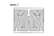
- test Example 1 sample No. 1 in which the flow path shown in FIGS. 1-No. Three grooved bipolar plates were prepared.
- the material of the bipolar plate is plastic carbon.
- the bipolar plate No. 3 has the same shape and size, and only the flow path is different, and the electrode contact area A on the surface facing the electrode and the planar opening area B of the grooves constituting the flow path are different.
- the area (A + B) of the opposing surface of each bipolar plate is the same at 891 mm 2 (27 mm ⁇ 33 mm).
- Table 1 shows the electrode contact area A of the bipolar plate in each sample and the ratio [A / (A + B)] of the electrode contact area (A) to the area (A + B) of the facing surface.
- the numerical value of the electrode contact area ratio [A / (A + B)] shown in Table 1 is a value obtained by rounding down the third decimal place.
- Sample No. 1-No. A single cell RF battery was assembled using 3 bipolar plates.
- the single cell was prepared by placing positive and negative electrodes on both sides of the diaphragm and sandwiching the cell frame with bipolar plates from both sides. Carbon felt was used for each positive and negative electrode.
Landscapes
- Life Sciences & Earth Sciences (AREA)
- Engineering & Computer Science (AREA)
- Manufacturing & Machinery (AREA)
- Sustainable Development (AREA)
- Sustainable Energy (AREA)
- Chemical & Material Sciences (AREA)
- Chemical Kinetics & Catalysis (AREA)
- Electrochemistry (AREA)
- General Chemical & Material Sciences (AREA)
- Fuel Cell (AREA)
Abstract
Selon l'invention, une plaque bipolaire comporte des faces opposées, lesquelles font face à des électrodes de batterie à flux redox, ainsi qu'au moins une rainure située sur ces faces opposées et formant un trajet d'écoulement dans lequel passe un électrolyte. Dans une vue en plan de cette plaque bipolaire, au moins une rainure présente une partie incurvée.
Priority Applications (3)
| Application Number | Priority Date | Filing Date | Title |
|---|---|---|---|
| PCT/JP2018/021776 WO2019234867A1 (fr) | 2018-06-06 | 2018-06-06 | Plaque bipolaire, cadre de cellule, empilement de cellules et batterie à flux redox |
| JP2020523917A JP7101771B2 (ja) | 2018-06-06 | 2018-06-06 | 双極板、セルフレーム、セルスタック、及びレドックスフロー電池 |
| TW108119513A TW202002379A (zh) | 2018-06-06 | 2019-06-05 | 雙極板、單元框、單元堆、及氧化還原液流電池 |
Applications Claiming Priority (1)
| Application Number | Priority Date | Filing Date | Title |
|---|---|---|---|
| PCT/JP2018/021776 WO2019234867A1 (fr) | 2018-06-06 | 2018-06-06 | Plaque bipolaire, cadre de cellule, empilement de cellules et batterie à flux redox |
Publications (1)
| Publication Number | Publication Date |
|---|---|
| WO2019234867A1 true WO2019234867A1 (fr) | 2019-12-12 |
Family
ID=68769771
Family Applications (1)
| Application Number | Title | Priority Date | Filing Date |
|---|---|---|---|
| PCT/JP2018/021776 Ceased WO2019234867A1 (fr) | 2018-06-06 | 2018-06-06 | Plaque bipolaire, cadre de cellule, empilement de cellules et batterie à flux redox |
Country Status (3)
| Country | Link |
|---|---|
| JP (1) | JP7101771B2 (fr) |
| TW (1) | TW202002379A (fr) |
| WO (1) | WO2019234867A1 (fr) |
Cited By (1)
| Publication number | Priority date | Publication date | Assignee | Title |
|---|---|---|---|---|
| CN116404195A (zh) * | 2022-10-09 | 2023-07-07 | 北京德泰储能科技有限公司 | 一种一体双极液流电池电极框及其全钒液流电池 |
Citations (6)
| Publication number | Priority date | Publication date | Assignee | Title |
|---|---|---|---|---|
| JPS5040690B1 (fr) * | 1970-09-19 | 1975-12-26 | ||
| JPS638568U (fr) * | 1986-07-02 | 1988-01-20 | ||
| JPH02148659A (ja) * | 1988-11-30 | 1990-06-07 | Toyobo Co Ltd | レドックスフロー型電池 |
| JPH08287923A (ja) * | 1995-04-13 | 1996-11-01 | Toyobo Co Ltd | 液流通型電解槽用電極材 |
| JP2000260461A (ja) * | 1999-03-05 | 2000-09-22 | Sumitomo Electric Ind Ltd | 流体流通型電池用セル |
| JP2015210849A (ja) * | 2014-04-23 | 2015-11-24 | 住友電気工業株式会社 | 双極板、レドックスフロー電池、及び双極板の製造方法 |
-
2018
- 2018-06-06 JP JP2020523917A patent/JP7101771B2/ja active Active
- 2018-06-06 WO PCT/JP2018/021776 patent/WO2019234867A1/fr not_active Ceased
-
2019
- 2019-06-05 TW TW108119513A patent/TW202002379A/zh unknown
Patent Citations (6)
| Publication number | Priority date | Publication date | Assignee | Title |
|---|---|---|---|---|
| JPS5040690B1 (fr) * | 1970-09-19 | 1975-12-26 | ||
| JPS638568U (fr) * | 1986-07-02 | 1988-01-20 | ||
| JPH02148659A (ja) * | 1988-11-30 | 1990-06-07 | Toyobo Co Ltd | レドックスフロー型電池 |
| JPH08287923A (ja) * | 1995-04-13 | 1996-11-01 | Toyobo Co Ltd | 液流通型電解槽用電極材 |
| JP2000260461A (ja) * | 1999-03-05 | 2000-09-22 | Sumitomo Electric Ind Ltd | 流体流通型電池用セル |
| JP2015210849A (ja) * | 2014-04-23 | 2015-11-24 | 住友電気工業株式会社 | 双極板、レドックスフロー電池、及び双極板の製造方法 |
Cited By (1)
| Publication number | Priority date | Publication date | Assignee | Title |
|---|---|---|---|---|
| CN116404195A (zh) * | 2022-10-09 | 2023-07-07 | 北京德泰储能科技有限公司 | 一种一体双极液流电池电极框及其全钒液流电池 |
Also Published As
| Publication number | Publication date |
|---|---|
| TW202002379A (zh) | 2020-01-01 |
| JPWO2019234867A1 (ja) | 2021-06-17 |
| JP7101771B2 (ja) | 2022-07-15 |
Similar Documents
| Publication | Publication Date | Title |
|---|---|---|
| CN108352554B (zh) | 双极板、电池框架、电池堆以及氧化还原液流电池 | |
| CN107710487B (zh) | 双极板、电池框架、电池堆和氧化还原液流电池 | |
| WO2017150170A1 (fr) | Électrode et batterie du type à circulation de solution électrolytique | |
| WO2015162954A1 (fr) | Plaque bipolaire, cuve de circulation d'oxydoréduction et procédé de production de plaque bipolaire | |
| JP6970388B2 (ja) | レドックスフロー電池用電極、レドックスフロー電池セル及びレドックスフロー電池 | |
| WO2019234869A1 (fr) | Plaque bipolaire, cadre de cellule, empilement de cellules et batterie à flux redox | |
| KR20170034995A (ko) | 플로우 프레임 및 그를 갖는 레독스 플로우 이차전지 | |
| JP7347448B2 (ja) | 電池セル、セルスタック、及びレドックスフロー電池 | |
| JP7101771B2 (ja) | 双極板、セルフレーム、セルスタック、及びレドックスフロー電池 | |
| JP7435479B2 (ja) | 電池セル、セルスタック、及びレドックスフロー電池 | |
| JP6525120B1 (ja) | セルフレーム、セルスタック、およびレドックスフロー電池 | |
| TW202036971A (zh) | 電池單元、單元堆及氧化還原電池 | |
| JP7281094B2 (ja) | 双極板、セルフレーム、セルスタック、およびレドックスフロー電池 | |
| JP7068613B2 (ja) | レドックスフロー電池セル及びレドックスフロー電池 | |
| WO2019234868A1 (fr) | Plaque bipolaire, cadre de cellule, empilement de cellules et batterie à flux redox | |
| JP7461614B2 (ja) | 双極板、セルフレーム、電池セル、セルスタック、及びレドックスフロー電池 | |
| KR20200045938A (ko) | 레독스 플로우 전지 셀, 레독스 플로우 전지 셀 스택, 및 레독스 플로우 전지 | |
| JP2020173892A (ja) | 双極板、電池セル、セルスタック、およびレドックスフロー電池 |
Legal Events
| Date | Code | Title | Description |
|---|---|---|---|
| 121 | Ep: the epo has been informed by wipo that ep was designated in this application |
Ref document number: 18921682 Country of ref document: EP Kind code of ref document: A1 |
|
| ENP | Entry into the national phase |
Ref document number: 2020523917 Country of ref document: JP Kind code of ref document: A |
|
| NENP | Non-entry into the national phase |
Ref country code: DE |
|
| 122 | Ep: pct application non-entry in european phase |
Ref document number: 18921682 Country of ref document: EP Kind code of ref document: A1 |