WO2020003384A1 - Système d'acquisition de planéité et machine de montage - Google Patents
Système d'acquisition de planéité et machine de montage Download PDFInfo
- Publication number
- WO2020003384A1 WO2020003384A1 PCT/JP2018/024223 JP2018024223W WO2020003384A1 WO 2020003384 A1 WO2020003384 A1 WO 2020003384A1 JP 2018024223 W JP2018024223 W JP 2018024223W WO 2020003384 A1 WO2020003384 A1 WO 2020003384A1
- Authority
- WO
- WIPO (PCT)
- Prior art keywords
- imaging device
- unit
- relative position
- flatness
- imaging
- Prior art date
- Legal status (The legal status is an assumption and is not a legal conclusion. Google has not performed a legal analysis and makes no representation as to the accuracy of the status listed.)
- Ceased
Links
Images






Classifications
-
- G—PHYSICS
- G01—MEASURING; TESTING
- G01B—MEASURING LENGTH, THICKNESS OR SIMILAR LINEAR DIMENSIONS; MEASURING ANGLES; MEASURING AREAS; MEASURING IRREGULARITIES OF SURFACES OR CONTOURS
- G01B11/00—Measuring arrangements characterised by the use of optical techniques
- G01B11/24—Measuring arrangements characterised by the use of optical techniques for measuring contours or curvatures
-
- G—PHYSICS
- G01—MEASURING; TESTING
- G01B—MEASURING LENGTH, THICKNESS OR SIMILAR LINEAR DIMENSIONS; MEASURING ANGLES; MEASURING AREAS; MEASURING IRREGULARITIES OF SURFACES OR CONTOURS
- G01B11/00—Measuring arrangements characterised by the use of optical techniques
- G01B11/30—Measuring arrangements characterised by the use of optical techniques for measuring roughness or irregularity of surfaces
-
- H—ELECTRICITY
- H05—ELECTRIC TECHNIQUES NOT OTHERWISE PROVIDED FOR
- H05K—PRINTED CIRCUITS; CASINGS OR CONSTRUCTIONAL DETAILS OF ELECTRIC APPARATUS; MANUFACTURE OF ASSEMBLAGES OF ELECTRICAL COMPONENTS
- H05K13/00—Apparatus or processes specially adapted for manufacturing or adjusting assemblages of electric components
- H05K13/08—Monitoring manufacture of assemblages
Definitions
- the present disclosure relates to a flatness obtaining system for obtaining flatness and a mounting machine.
- Patent Literature 1 describes a lift detection device that detects whether or not each of the lead wires of a component includes a component body and a plurality of lead wires that extend side by side from four side surfaces of the component body. Have been.
- the lift detection device includes a slit light source that irradiates slit light to a plurality of lead wires extending in a line from one side surface of the component held by the component holder, and a plurality of lead wires that are irradiated with the slit light.
- a camera for imaging the plurality of lead wires based on the captured image. The component is rotated after detecting the presence or absence of floating of the plurality of lead wires, and detecting the presence or absence of each of the plurality of lead wires extending from another side surface.
- the relative position in the first direction which is a direction parallel to the axis of the imaging device, between the object holder that holds the object and the imaging device is the first position of the target portion of the object. It is changed between the case where one part is imaged and the case where the second part is imaged. For example, when a part of the target portion of the object is out of the depth of field of the imaging device and the first part including the part is imaged, the first part is located within the depth of field.
- the relative position in the first direction between the object holder and the imaging device can be changed so as to be located.
- the relative position of the object holder and the imaging device in the first direction depends on whether the first part of the target part of the object is imaged or the second part excluding the first part is imaged. Is changed, and a good captured image can be obtained for the first portion, and the flatness of the target portion can be obtained well.
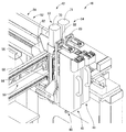
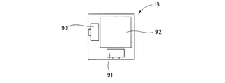
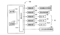
- FIG. 3 is a diagram showing a component mounting device of the mounting machine. It is a front view of the imaging unit of the above-mentioned mounting machine. It is a top view of the above-mentioned imaging unit. It is a figure which shows notionally the periphery of the control apparatus of the said mounting machine.
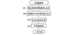
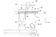
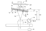
- 4 is a flowchart illustrating a flatness acquisition program stored in a storage unit of the control device. It is a flowchart showing a part of said program. It is a figure showing the state where part B1 of a part is imaged by the above-mentioned imaging unit. It is a figure showing the state where the part B2 of the above-mentioned parts is imaged.
- This mounting machine includes a flatness acquisition system.
- the mounting machine 4 mounts an electronic component (hereinafter, abbreviated as a component) on a circuit board S (hereinafter, abbreviated as a board S). , A component supply device 14, a component mounting device 16, an imaging unit 18, and the like.
- the substrate transport and support device 12 transports and holds the substrate S.
- x is the transport direction of the substrate S by the substrate transport and support device 12
- y is the width direction of the substrate S
- z is the thickness direction of the substrate S.
- y is the front-back direction of the mounting machine 4
- z is the up-down direction, and these x-direction, y-direction, and z-direction are orthogonal to each other.
- the component supply device 14 supplies a component to be mounted on the board S to the component mounting device 16 in a state where it can be delivered.
- the component supply device 14 includes at least one of a tray type supply device having a tray 20, a tape feeder type supply device having a tape feeder (not shown), and a loose component supply device 21.
- the components supplied by the component supply device 14 include a component 30 including a component main body 26 and a plurality of solder balls 28 as electrode portions formed on the component main body 26. As shown in FIG.
- the SOJ is a lead component 36 including a component main body 32 and a plurality of lead wires 34 extending from the side surface of the component main body 32 and serving as electrode portions bent in a J-shape. (Small Out Line J Lead).
- the component mounting device 16 picks up and holds the component supplied by the component supply device 14, and mounts the component on the substrate S transported and supported by the substrate transport and support device 12.
- the component mounting device 16 includes two heads 40 and 41, a head moving device 42 that moves the two heads 40 and 41, and the like.
- the head moving device 42 includes an x-direction moving device 50 for simultaneously moving the two heads 40 and 41 in the x-direction, a y-direction moving device 52 for moving in the y-direction, and a z-direction moving device 53 for individually moving in the z-direction. 54 and the like.
- the y direction moving device 52 includes a y slider 55, a y motor 56 which is a linear motor, and the like.
- the x-direction moving device 50 is provided on the y-slider 55, and includes an x-slider 60, an x-motor 62 as a driving source, a motion converting mechanism 64 for converting the rotation of the x-motor 62 into a linear movement and transmitting the linear movement to the x-slider 60. .
- the z-direction moving devices 53 and 54 are provided on the x-slider 60, and convert z-sliders 68 and 69, z-motors 70 and 71 as driving sources, and z-motors 70 and 71 into linear motion, respectively, to convert the z-sliders 68 into linear motions. , 69, and a motion conversion mechanism (not shown).
- the head 40 of the two heads 40 and 41 has one component holder 80.
- the component holder 80 can be, for example, a suction nozzle that suctions and holds components by negative pressure, or a chuck that holds components by a pair of claws.
- the imaging unit 18 is for acquiring the three-dimensional shape of the component held by the component holder 80 positioned above, and as shown in FIGS. 3 and 4, two projectors 90 and 91 and an imaging device as an imaging device. It includes a camera 92 and a three-dimensional shape acquiring unit 94 which mainly controls a computer, and controls the projectors 90 and 91 and the camera 92 and acquires a three-dimensional shape of a target portion of an object.
- the camera 92 is an imaging device having an imaging element such as a charge coupled device (CCD) and a complementary metal oxide semiconductor (CMOS).
- CCD charge coupled device
- CMOS complementary metal oxide semiconductor
- the camera 92 is provided so that the axis Lz extends in the z direction, and the projectors 90 and 91 are provided at positions separated by 90 ° around the axis Lz.
- the projectors 90 and 91 respectively irradiate a pattern that spreads in a plane in which the intensity changes sinusoidally in one direction in a direction inclined with respect to the z direction, the x direction, and the y direction.
- an imaging region Rc which is an area where an image can be captured by the camera 92 is included in an irradiation area Rp which is an area where a pattern is irradiated by the projectors 90 and 91.
- a part of the component irradiated with the pattern by the projectors 90 and 91 is imaged by the camera 92, and is positioned inside the imaging region Rc by the three-dimensional shape acquisition unit 94 based on the acquired image.
- the three-dimensional shape of the part (part) of the part is obtained by the phase shift method.
- a pattern whose intensity changes sinusoidally in one direction is emitted a plurality of times by shifting the phase by the projectors 90 and 91, respectively.
- the camera 92 obtains a captured image that is an image in the imaging region Rc.
- the three-dimensional shape obtaining unit 94 obtains the luminance of each of the pixels constituting the captured image, and obtains the phase of the pixel based on the luminance value of the same pixel in the plurality of captured images. Is done. Then, by connecting pixels having the same phase, an equal phase line is obtained.
- the irradiation angle of the phase light one line forming the pattern
- the position of the pixel on the image sensor of the camera 92 the optical or geometric parameters of the image pickup unit 18 (the optical center coordinates of the projectors 90 and 91,
- the distance between the image sensor of the camera 92 and the point on the component corresponding to each of the pixels connected by the equiphase lines is acquired based on the optical center coordinates of the camera 92, the focal length, and the like.
- the three-dimensional shape of the target portion of the component is obtained based on the distance between the plurality of points on the component and the image sensor of the camera 92.
- the method of acquiring the three-dimensional shape and the pattern irradiated by the projectors 90 and 91 are not limited.
- a three-dimensional shape can be obtained not only by the phase shift method but also widely by a pattern projection method, or a three-dimensional shape can be obtained by a stereo image method, a contour method, or the like.
- the three-dimensional shape of the component located in the predetermined two-dimensionally (planarly) set area may be obtained.
- a projector is unnecessary, and a three-dimensional shape of a component located in the imaging region Rc is obtained based on images captured by a plurality of cameras.
- the control device 100 mainly includes a computer, and includes an execution unit 110, a storage unit 112, an input / output unit 114, and the like, as shown in FIG.
- the shape acquisition unit 94 is connected, and the substrate transport support device 12, the component supply device 14, the component mounting device 16, and the like are connected via the drive circuit 120.
- the component holder 80 is moved above the imaging unit 18, and the three-dimensional shape of the target part of the component held by the component holder 80 is acquired by the imaging unit 18.
- the target part of the component refers to a portion of the component opposite to the surface facing the component holder 80, in other words, a portion of the component mounted on the substrate S.
- a part of the solder ball 28 may be missing or the lead wire 34 may be bent due to a manufacturing defect or a trouble during transportation.
- a problem such as the occurrence of poor current supply to the components 30 and 36 occurs. . Therefore, in the present embodiment, the flatness of the target portion of the components 30 and 36 is acquired, and the components 30 and 36 are checked.
- a portion including the plurality of solder balls 28 and the like is set as the target portion Ta, and based on the three-dimensional shape of the target portion Ta, the tip of the plurality of solder balls 28
- the flatness of the virtual plane Pa formed by the set of (points) is obtained.
- a portion including a portion of the plurality of lead wires 34 located below the component body 32 and the like is defined as the target portion Tb, and the lead wire is formed based on the three-dimensional shape of the target portion Tb.
- the flatness of an imaginary plane Pb formed by a set of predetermined points on the lower side surface of the part located below the component main body 32 of 34 is acquired.
- the target part Ta of the component held by the component holder 80 (for example, the case where the component 30 is held) is wider than the imaging region Rc of the imaging unit 18, as shown in FIG.
- a captured image including the entire target portion Ta of the component 30 cannot be obtained.
- the component holder 80 is moved in the horizontal direction by the x-direction moving device 50 and the y-direction moving device 52. Thereby, the portion of the target portion Ta of the component 30 located in the imaging region Rc is moved, and the portion located in the imaging region Rc is changed. Each time a portion located in the imaging region Rc is changed, an image is taken by the camera 92 to obtain a three-dimensional shape.
- FIG. 10 is a diagram illustrating a state in which the component 30 is viewed from the target portion Ta. Black arrows indicate the moving directions of the portions B1 to B9 located in the imaging region Rc.
- the depth of field C refers to a range in which a clear image can be obtained as a captured image before and after a focused object in the camera 92, and is determined by the characteristics of the camera 92. For a part Bx that deviates from the depth of field C, the captured image becomes unclear, and it is difficult to accurately obtain a three-dimensional shape.
- the inclination k1 of the part B1 is obtained.
- k1 (h2-h1) / w
- the two points Q1 and Q2 are two points separated in the direction indicated by the arrow F1, that is, in the direction of the relative movement between the component holder 80 and the camera 92.
- Q2 is the distance in the direction parallel to the arrow F1
- the slope k is the slope of the portion B1 in the direction parallel to the arrow F1.
- the direction indicated by the arrow F4 in the part B3 is obtained based on the heights h5 and h6 of the two points Q5 and Q6 separated from each other and the distance w3 in the direction parallel to the arrow F4 between the points Q5 and Q6. .
- the height h4 * of the end E4 is obtained based on the inclination k3 and the distance x3 in a direction parallel to the arrow F4 between the point Q6 and the end E4 of the part B4 on the far side from the part B3. , Is located within the depth of field C. According to the determination result, the component holder 80 is moved in the horizontal direction, or is moved in the horizontal direction and the vertical direction.
- a three-dimensional shape is obtained for each of the portions B1 to B9, and the obtained three-dimensional shapes are combined to obtain a three-dimensional shape of the entire target portion.
- the three-dimensional shapes acquired for each of a plurality of parts can be combined based on the elevation amount ⁇ H of the component holder 80. For example, when the component holder 80 is moved up and down by ⁇ H when the part B2 is imaged, the three-dimensional shape acquired for the part B1 and the three-dimensional shape acquired for the part B2 are shifted by an amount of elevation ⁇ H. It combines the three-dimensional shape.
- the three-dimensional shape obtained for the portion B1 and the three-dimensional shape obtained for the portion B2 are acquired such that the three-dimensional shape of the overlapping portion Bs1 of the portion B1 matches the three-dimensional shape of the overlapping portion Bs1 of the portion B2.
- the heights of one or more points included in the overlapping portion Bs1 are obtained based on the captured image including the portion B1 (hd1), and are obtained based on the captured image including the portion B2 (hd2).
- the three-dimensional shape acquired in the portion B2 is shifted so that the heights hd1 and hd2 match.
- the flatness acquisition program in that case will be described with reference to the flowchart of FIG.
- This program is executed by the control device 100, and every time the component holder 80 is moved in the horizontal direction, a three-dimensional shape acquisition command is output to the three-dimensional shape acquisition unit 94.
- a pattern is emitted by the projectors 90 and 91 under the control of the three-dimensional shape acquisition unit 94, and a captured image is acquired by the camera 92. Then, a three-dimensional shape is acquired based on the captured image and supplied to the control device 100.
- step 1 (hereinafter abbreviated as S1; the same applies to other steps), a count value n of a counter that counts the number of portions where the three-dimensional shape has been acquired is initialized (set to 0), and S2 is performed.
- the component holder 80 is moved to a predetermined three-dimensional shape acquisition start position above the imaging unit 18. For example, for the component 30, the position of the component holder 80 where the portion B1 in FIG. 10 is located within the imaging region Rc can be set as the three-dimensional shape acquisition start position.
- S3 a three-dimensional shape acquisition command is output to the imaging unit 18. Thereby, the three-dimensional shape of the portion B1 is obtained, supplied to the control device 100, and stored.
- the count value of the counter for counting the number of parts is increased by one, and in S5, it is determined whether the count value is equal to or more than the set value Ns.
- the set value Ns is the number of the parts B1 to B9 set in the target part Ta of the component 30, and is 9, for example, for the component 30 shown in FIG.
- the component holder 80 is moved in the horizontal direction and moved up and down.
- the elevating amount is determined such that the height h2 * of the end E2 of the portion B2 is within the depth of field C.
- S3 and subsequent steps are similarly executed, and S3 to S11 are repeatedly executed. Meanwhile, if the number of the portions where the three-dimensional shape is obtained becomes equal to or more than Ns, the determination in S5 becomes YES, and in S12, the flatness of the component is obtained.
- the component holder 80 is moved up and down to position the portion located in the imaging region Rc within the depth of field. This makes it possible to accurately acquire the three-dimensional shape of the target portion Ta of the component 30, and to accurately acquire the flatness.
- the object corresponds to the components 30 and 36
- the object holder corresponds to the component holder 80
- the first direction corresponds to the vertical direction
- the second direction corresponds to the horizontal direction.
- the second direction may be the direction of relative movement between the component holder 80 (head 40) and the camera 92.
- the functional portion corresponds to the electrode portion
- the first portion corresponds to the portion B1
- the second portion corresponds to the portion B2.
- the distance acquisition unit and the height acquisition unit are configured by a part that acquires the three-dimensional shape of the target part of the three-dimensional shape acquisition unit 94, and the like.
- the flatness acquisition unit is configured by a portion that stores and executes S12 of the flatness acquisition program of the control device 100, and the first direction relative position change unit and the portion that the relative height control unit stores S11 execute.
- the second direction relative position changing unit is constituted by a part for storing and executing S9 and S10, and the like.
- the second direction relative position changing unit includes the first direction relative position changing unit and the second direction relative position changing unit.
- a position changing unit is configured.
- the x-direction moving device 50 and the y-direction moving device 52 constitute a horizontal moving device, and the z-direction moving device 53 constitutes a vertical moving device.
- the distance acquisition unit control unit and the height acquisition control unit are configured by a part that stores and executes S3
- the inclination acquisition unit is configured by a part that stores S6 and an execution unit
- the determination unit is performed by S8.
- a part to execute It should be noted that a flatness acquisition system is configured by the imaging unit 18, the portion of the control device 100 that stores and executes the flatness acquisition program represented by the flowchart in FIG. 6, and the like.
- the height h2 * of the end E2 of the portion B2 is acquired based on the inclination k1 of the portion B1, and when the height h2 * is out of the depth of field, the component holding is performed.
- the tool 80 is moved in the horizontal direction and in the vertical direction, it is not essential to acquire the height h2 * of the end E2.
- the component holder 80 is horizontally moved without acquiring the height k2 * of the end E2, while acquiring the inclination k1 of the portion B1.
- the height h2 * of the end E2 of the part B2 is determined based on the inclination k1 of the part B1.
- the component holder 80 can be raised and lowered so that the height h2 * of the end E2 is located within the depth of field. Also, it is not essential to acquire the inclination k1 of the portion B1. For example, as a result of moving the component holder 80 in the horizontal direction so that the portion located in the imaging region Rc is changed from the portion B1 to the portion B2 and imaging the portion B2 with the camera 92, at least a portion of the portion B2 is obtained. When it is out of the depth of field, the component holder 80 can be moved up and down as appropriate to position the portion B2 within the depth of field.
- the imaging unit 18 acquires the three-dimensional shape of the target portion of the component, but only the height of a plurality of points of the portion from the imaging device of the camera 92 may be acquired. For example, based on the height of the tip (point) of the solder ball 28 of the component 30 from the image sensor of the camera 92, the flatness of the virtual plane Pa can be obtained.
- the portions when a plurality of portions are set in the target portion, it is not essential that the portions have overlapping portions. Further, it is not essential to apply the flatness acquisition system to the mounting machine 4, and the flatness acquisition system may be executed in a single system.
- the present invention can be implemented in a mode in which various changes are made based on the above.
- Control unit # 10 Control device $ 18: Imaging unit $ 40: Head $ 42: Head moving device $ 50: X direction moving device $ 52: Y direction moving device $ 54: Z direction moving device $ 80: Component holder $ 90, 91: Projector $ 92: Camera # 94: Three-dimensional shape acquisition unit # 100: Control unit # 110: Execution unit # 112: Storage unit
Landscapes
- Engineering & Computer Science (AREA)
- Physics & Mathematics (AREA)
- General Physics & Mathematics (AREA)
- Operations Research (AREA)
- Manufacturing & Machinery (AREA)
- Microelectronics & Electronic Packaging (AREA)
- Length Measuring Devices By Optical Means (AREA)
- Supply And Installment Of Electrical Components (AREA)
Abstract
La présente invention est une amélioration d'un système d'acquisition de planéité, et aborde le problème de l'acquisition satisfaisante de la planéité d'une partie objectif d'un objet même lorsqu'une partie de la partie objectif de l'objet est à l'extérieur de la profondeur de champ d'un dispositif d'imagerie. Dans ledit système d'acquisition de planéité, les positions relatives d'un dispositif d'imagerie et d'un support d'objet permettant de retenir l'objet, dans une première direction parallèle à une ligne d'axe du dispositif d'imagerie, sont modifiées lorsqu'une première partie de la partie objectif de l'objet est imagée et lorsqu'une seconde partie de celle-ci est imagée. Par exemple, lorsqu'une partie de la partie objectif de l'objet est en dehors de la profondeur de champ du dispositif d'imagerie, les positions relatives du support d'objet et du dispositif d'imagerie dans la première direction peuvent être modifiées de sorte que la première partie comprenant la partie de la partie objectif de l'objet soit positionnée à l'intérieur de la profondeur de champ. Par conséquent, une image capturée qui est satisfaisante même dans la première partie peut être acquise, et la planéité de la partie objectif peut être acquise de manière satisfaisante.
Priority Applications (2)
| Application Number | Priority Date | Filing Date | Title |
|---|---|---|---|
| PCT/JP2018/024223 WO2020003384A1 (fr) | 2018-06-26 | 2018-06-26 | Système d'acquisition de planéité et machine de montage |
| JP2020526757A JP7181292B2 (ja) | 2018-06-26 | 2018-06-26 | 平坦度取得システムおよび実装機 |
Applications Claiming Priority (1)
| Application Number | Priority Date | Filing Date | Title |
|---|---|---|---|
| PCT/JP2018/024223 WO2020003384A1 (fr) | 2018-06-26 | 2018-06-26 | Système d'acquisition de planéité et machine de montage |
Publications (1)
| Publication Number | Publication Date |
|---|---|
| WO2020003384A1 true WO2020003384A1 (fr) | 2020-01-02 |
Family
ID=68986854
Family Applications (1)
| Application Number | Title | Priority Date | Filing Date |
|---|---|---|---|
| PCT/JP2018/024223 Ceased WO2020003384A1 (fr) | 2018-06-26 | 2018-06-26 | Système d'acquisition de planéité et machine de montage |
Country Status (2)
| Country | Link |
|---|---|
| JP (1) | JP7181292B2 (fr) |
| WO (1) | WO2020003384A1 (fr) |
Cited By (4)
| Publication number | Priority date | Publication date | Assignee | Title |
|---|---|---|---|---|
| US20210254970A1 (en) * | 2020-02-19 | 2021-08-19 | Faro Technologies, Inc. | System and method for verifying a position of a component on an object |
| US20220037175A1 (en) * | 2018-10-15 | 2022-02-03 | Koh Young Technology Inc. | Apparatus, method and recording medium storing command for inspection |
| WO2024189795A1 (fr) * | 2023-03-14 | 2024-09-19 | 株式会社Fuji | Machine de montage de composant |
| CN119043253A (zh) * | 2024-10-31 | 2024-11-29 | 山东申鑫新材料有限公司 | 一种用于幕墙铝板复合板材的平整度检测装置 |
Citations (4)
| Publication number | Priority date | Publication date | Assignee | Title |
|---|---|---|---|---|
| JP2007121981A (ja) * | 2005-09-30 | 2007-05-17 | Matsushita Electric Ind Co Ltd | 基板検査方法 |
| US20090180679A1 (en) * | 1998-07-08 | 2009-07-16 | Charles A. Lemaire | Method and apparatus for parts manipulation, inspection, and replacement |
| JP2013115383A (ja) * | 2011-11-30 | 2013-06-10 | Fuji Mach Mfg Co Ltd | 電子部品実装装置 |
| JP2017142188A (ja) * | 2016-02-12 | 2017-08-17 | Ckd株式会社 | 三次元計測装置 |
-
2018
- 2018-06-26 WO PCT/JP2018/024223 patent/WO2020003384A1/fr not_active Ceased
- 2018-06-26 JP JP2020526757A patent/JP7181292B2/ja active Active
Patent Citations (4)
| Publication number | Priority date | Publication date | Assignee | Title |
|---|---|---|---|---|
| US20090180679A1 (en) * | 1998-07-08 | 2009-07-16 | Charles A. Lemaire | Method and apparatus for parts manipulation, inspection, and replacement |
| JP2007121981A (ja) * | 2005-09-30 | 2007-05-17 | Matsushita Electric Ind Co Ltd | 基板検査方法 |
| JP2013115383A (ja) * | 2011-11-30 | 2013-06-10 | Fuji Mach Mfg Co Ltd | 電子部品実装装置 |
| JP2017142188A (ja) * | 2016-02-12 | 2017-08-17 | Ckd株式会社 | 三次元計測装置 |
Cited By (7)
| Publication number | Priority date | Publication date | Assignee | Title |
|---|---|---|---|---|
| US20220037175A1 (en) * | 2018-10-15 | 2022-02-03 | Koh Young Technology Inc. | Apparatus, method and recording medium storing command for inspection |
| US11694916B2 (en) * | 2018-10-15 | 2023-07-04 | Koh Young Technology Inc. | Apparatus, method and recording medium storing command for inspection |
| US12051606B2 (en) | 2018-10-15 | 2024-07-30 | Koh Young Technology Inc. | Apparatus, method and recording medium storing command for inspection |
| US20210254970A1 (en) * | 2020-02-19 | 2021-08-19 | Faro Technologies, Inc. | System and method for verifying a position of a component on an object |
| US11867499B2 (en) * | 2020-02-19 | 2024-01-09 | Faro Technologies, Inc. | System and method for verifying a position of a component on an object |
| WO2024189795A1 (fr) * | 2023-03-14 | 2024-09-19 | 株式会社Fuji | Machine de montage de composant |
| CN119043253A (zh) * | 2024-10-31 | 2024-11-29 | 山东申鑫新材料有限公司 | 一种用于幕墙铝板复合板材的平整度检测装置 |
Also Published As
| Publication number | Publication date |
|---|---|
| JP7181292B2 (ja) | 2022-11-30 |
| JPWO2020003384A1 (ja) | 2021-07-15 |
Similar Documents
| Publication | Publication Date | Title |
|---|---|---|
| JP7181292B2 (ja) | 平坦度取得システムおよび実装機 | |
| CN105309064B (zh) | 元件安装装置和元件安装方法 | |
| EP3322275B1 (fr) | Dispositif de montage, procédé de traitement de photographies et unité de photographie | |
| JP6378839B2 (ja) | 部品実装装置および部品実装装置における部品実装判定方法 | |
| JP6712260B2 (ja) | 実装装置、撮像処理方法及び撮像ユニット | |
| JP6411663B2 (ja) | 部品実装装置 | |
| WO2015045649A1 (fr) | Dispositif de montage de composants | |
| JP6147016B2 (ja) | 組立機 | |
| JP5507378B2 (ja) | 電子部品実装装置 | |
| JP6849815B2 (ja) | 部品実装装置、撮影方法、実装順序の決定方法 | |
| US10869421B2 (en) | Mounting device and imaging processing method | |
| JP2013236011A (ja) | 部品実装装置 | |
| JP7095089B2 (ja) | 実装機および実装システム | |
| JP6990309B2 (ja) | 表面実装機 | |
| JP2013096831A (ja) | 部品実装基板生産装置、および、三次元形状測定装置 | |
| TWI897626B (zh) | 檢查系統、半導體製造裝置及檢查方法 | |
| JP6670590B2 (ja) | 画像生成装置、実装装置及び画像生成方法 | |
| CN117280885A (zh) | 识别装置以及识别方法 | |
| CN117222861A (zh) | 测定装置及基板检查装置 | |
| JP2016151538A (ja) | 部品判定装置 | |
| JP6204050B2 (ja) | 電子部品装着機 | |
| WO2024189795A1 (fr) | Machine de montage de composant | |
| WO2024111022A1 (fr) | Dispositif d'inspection d'aspect de composant et procédé d'inspection d'aspect de composant | |
| TWI709826B (zh) | 修正資訊產生方法、描繪方法、修正資訊產生裝置及描繪裝置 | |
| JP6759450B2 (ja) | 部品実装機、部品認識方法、外観検査機、外観検査方法 |
Legal Events
| Date | Code | Title | Description |
|---|---|---|---|
| 121 | Ep: the epo has been informed by wipo that ep was designated in this application |
Ref document number: 18923904 Country of ref document: EP Kind code of ref document: A1 |
|
| ENP | Entry into the national phase |
Ref document number: 2020526757 Country of ref document: JP Kind code of ref document: A |
|
| NENP | Non-entry into the national phase |
Ref country code: DE |
|
| 122 | Ep: pct application non-entry in european phase |
Ref document number: 18923904 Country of ref document: EP Kind code of ref document: A1 |