WO2020003389A1 - Cathéter à ballonnet - Google Patents
Cathéter à ballonnet Download PDFInfo
- Publication number
- WO2020003389A1 WO2020003389A1 PCT/JP2018/024255 JP2018024255W WO2020003389A1 WO 2020003389 A1 WO2020003389 A1 WO 2020003389A1 JP 2018024255 W JP2018024255 W JP 2018024255W WO 2020003389 A1 WO2020003389 A1 WO 2020003389A1
- Authority
- WO
- WIPO (PCT)
- Prior art keywords
- balloon
- catheter
- catheter shaft
- lumen
- fluid
- Prior art date
- Legal status (The legal status is an assumption and is not a legal conclusion. Google has not performed a legal analysis and makes no representation as to the accuracy of the status listed.)
- Ceased
Links
Images








Classifications
-
- A—HUMAN NECESSITIES
- A61—MEDICAL OR VETERINARY SCIENCE; HYGIENE
- A61F—FILTERS IMPLANTABLE INTO BLOOD VESSELS; PROSTHESES; DEVICES PROVIDING PATENCY TO, OR PREVENTING COLLAPSING OF, TUBULAR STRUCTURES OF THE BODY, e.g. STENTS; ORTHOPAEDIC, NURSING OR CONTRACEPTIVE DEVICES; FOMENTATION; TREATMENT OR PROTECTION OF EYES OR EARS; BANDAGES, DRESSINGS OR ABSORBENT PADS; FIRST-AID KITS
- A61F2/00—Filters implantable into blood vessels; Prostheses, i.e. artificial substitutes or replacements for parts of the body; Appliances for connecting them with the body; Devices providing patency to, or preventing collapsing of, tubular structures of the body, e.g. stents
- A61F2/95—Instruments specially adapted for placement or removal of stents or stent-grafts
- A61F2/958—Inflatable balloons for placing stents or stent-grafts
-
- A—HUMAN NECESSITIES
- A61—MEDICAL OR VETERINARY SCIENCE; HYGIENE
- A61M—DEVICES FOR INTRODUCING MEDIA INTO, OR ONTO, THE BODY; DEVICES FOR TRANSDUCING BODY MEDIA OR FOR TAKING MEDIA FROM THE BODY; DEVICES FOR PRODUCING OR ENDING SLEEP OR STUPOR
- A61M25/00—Catheters; Hollow probes
- A61M25/10—Balloon catheters
Definitions
- the present invention relates to a balloon catheter used for treating an aneurysm.
- stent graft insertion As a treatment for aortic aneurysms.
- indwelling stent grafts are usually crimped with an occlusion balloon catheter, and a balloon divided into three leaves is provided as such a balloon catheter.
- a Tri-Love balloon catheter has been introduced (see Non-Patent Document 1 below). According to the Tri-Love balloon catheter, even when the balloon is expanded in the aorta, it is said that a part of the peripheral blood flow can be maintained.
- the blood flow that can be secured from the gap between the three balloons constituting the Tri-Love balloon catheter is not sufficient. Further, the expansion force of these balloons is not sufficient to crimp the stent graft, and the crimping force of the three balloons on the stent graft varies in the circumferential direction.
- Patent Document 1 a bag-like material having elasticity is added to the distal end portion of a catheter, and this bag-like material is a flat film when no fluid is received therein.
- a dissociative aortic aneurysm treatment device which is tubular when fluid is received and in which the inner and outer membranes constituting the bag-like body are partially joined together has been proposed.
- the bag-like material (balloon) when the fluid is received inside becomes tubular, so that a sufficient blood flow to the periphery can be ensured.
- the expanding force of the bag-like material (substantially cylindrical balloon) at the time of receiving a fluid is not sufficient.
- the proximal end 2a of the bag-like material 2 (balloon) after contraction is perpendicular to the axial direction of the catheter 1 (catheter shaft).
- An object of the present invention is to provide a sufficient blood flow to the periphery when the balloon is expanded in the aneurysm, and to return the deflated balloon to a lumen such as a guiding catheter. Is to provide a balloon catheter that can perform the operation smoothly. It is another object of the present invention to provide a balloon catheter having a high roundness in a cross section and capable of uniformly generating a high expansion pressure in a circumferential direction.
- a balloon catheter includes a catheter shaft having a lumen (hereinafter, referred to as an “expansion lumen”) for flowing a fluid, a hub connected to a proximal end side of the catheter shaft, and the catheter.
- a tubular balloon connected to the distal end side of the shaft, The distal end portion of the catheter shaft is inserted into the lumen of the balloon while in contact with the inner wall surface of the balloon, or the inner wall surface of the balloon,
- a central axis of the catheter shaft is located at a position twisted with a tube axis of the balloon, and an angle between the catheter shaft and the tube axis is 45 ° or less.
- the “balloon tube wall” refers to a portion surrounding the lumen of the balloon, and includes a space (for example, the inside of a convex portion described later) sandwiched between the outer peripheral surface and the inner peripheral surface of the balloon.
- an angle between the central axis of the catheter shaft and the tube axis of the balloon is 15 to 30 °.
- the angle between the central axis of the catheter shaft and the tube axis of the balloon refers to the angle between a vector extending in the distal direction on the central axis and a vector extending in the distal direction on the tube axis.
- the stent graft placed in the aneurysm can be pressed against the inner wall surface of the aneurysm, and the blood flow to the periphery can be reduced. It can be sufficiently secured. Further, the distal end portion of the catheter shaft is inserted into the lumen of the balloon while being in contact with the inner wall surface of the balloon or the inner wall surface of the balloon, and the center axis of the catheter shaft and the tube axis of the balloon are aligned.
- the proximal end edge of the deflated balloon can be inclined with respect to an imaginary plane perpendicular to the central axis of the catheter shaft,
- this balloon is pulled back to the lumen of a guiding catheter or the like so as to be wrapped around a catheter shaft, the balloon can be smoothly pulled back without the proximal end of the balloon getting caught in the opening of the guiding catheter or the like. it can.
- the balloon preferably has a smooth outer peripheral surface. According to the balloon catheter having such a configuration, the stent graft placed in the aneurysm can be surely crimped by fitting it to the inner wall surface of the aneurysm.
- the inner periphery of the balloon is formed so as to extend obliquely with respect to the tube axis direction, and has convex portions having the same shape capable of accommodating a fluid therein. At least four are arranged along the direction, The insides of the protrusions communicate with each other, When the fluid supplied from the expansion lumen of the catheter shaft flows into the inside, each of the convex portions expands, and the adjacent convex portions come into contact with each other and press each other, whereby the Preferably, the balloon is inflated.
- the number of convex portions arranged on the inner periphery of the balloon is preferably 6 to 12, and particularly preferably 8.
- the balloon catheter having such a configuration, the balloon is expanded by expanding and pressing each other on the inner circumference of the balloon along the circumferential direction, so that the balloon expands.
- the catheter shaft is constituted by an inner tube having a guide wire lumen, and an outer tube forming the expansion lumen together with the inner tube.
- the distal end of the catheter shaft is inserted into any one of the protrusions (in the tube wall of the balloon), and the expansion is performed inside the protrusion.
- a fluid flowing through the working lumen is supplied.
- the fluid flowing through the expansion lumen is supplied to the inside of the convex portion through which the distal end portion of the catheter shaft is inserted, through the side hole formed in the tube wall of the outer tube.
- the fluid can be supplied to the inside of another protrusion communicating with the protrusion.
- the distal end of the catheter shaft is inserted into the lumen of the balloon while being in contact with any one of the convex surfaces of the convex portion. Further, a fluid flowing through the expansion lumen may be supplied.
- the fluid flowing through the expansion lumen is passed through the communication hole that communicates between the expansion lumen and the inside of the projection to the inside of the projection where the distal end of the outer tube is in contact.
- the fluid can also be supplied to the inside of another convex portion communicating with the convex portion.
- the convex surface of the convex portion is formed substantially flat.
- the blood flow to the periphery can be further secured, and the force when each of the protrusions expands and presses each other, and hence the expansion force of the balloon, is reduced. Can be increased.
- a distal end protruding portion which is capable of accommodating a fluid therein and has a height lower than the protruding portion is formed in the inner periphery of the distal end portion of the balloon along the circumferential direction. It is formed so as to extend, the inside of the tip protrusion communicates with the inside of each of the protrusions via a narrow channel,
- a rear end protruding portion capable of containing a fluid therein and having a height lower than the protruding portion is formed so as to extend along a circumferential direction, and the rear end protruding portion is formed.
- the inside of the portion communicates with the inside of each of the protrusions via a narrow channel, It is preferable that the insides of the protrusions communicate with each other.
- the distal end portion and the rear end portion of the balloon are formed such that the distal end convex portion and the rear end convex portion having a height lower than the convex portion are formed so as to extend along the circumferential direction.
- the balloon can be expanded without deforming or over-expanding the end portion, and the roundness of the cross section at the front end portion and the rear end portion of the balloon at the time of expansion becomes high.
- the balloon catheter of the present invention is suitably used for treating an aneurysm by stent graft insertion.
- the balloon catheter of this invention when the balloon which comprises this is expanded in an aneurysm, the blood flow to the periphery can be fully ensured, and the balloon in the contracted state is used as the guiding catheter. Such operations as pulling back to the lumen can be performed smoothly. Further, according to the balloon catheter of the above (3), the roundness of the cross section is high, and a high expansion pressure can be uniformly developed in the circumferential direction.
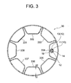
- FIG. 3 is a sectional view taken along the line III-III of FIG. 1.
- FIG. 4 is a sectional view taken along line IV-IV of FIG. 1.
- FIG. 5 is a sectional view taken along line VV of FIG. 1.
- FIG. 2 is a view showing a state where a balloon is deployed in the balloon catheter shown in FIG.
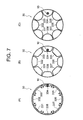
- FIG. 2 is a cross-sectional view showing a state where each of the convex portions of the balloon is expanded by the inflow of a fluid in the balloon catheter shown in FIG. 1.
- FIG. 2 is an explanatory view schematically showing the shape of a balloon in a contracted state, which is pulled back to the lumen of the guiding catheter in the balloon catheter shown in FIG. 1.
- FIG. 10 is a plan view of the balloon catheter shown in FIG. 9.
- FIG. 10 is a sectional view taken along the line XI-XI in FIG. 9.
- FIG. 12 is a sectional view taken along the line XII-XII in FIG. 9.
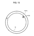
- FIG. 10 is a sectional view taken along line XIII-XIII in FIG. 9.
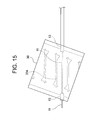
- FIG. 10 is a view showing a state where a balloon is deployed in the balloon catheter shown in FIG. 9.
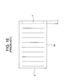
- It is explanatory drawing which shows the connection state of a catheter shaft and a balloon in the conventional balloon catheter.
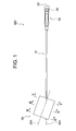
- the balloon catheter 100 of the present embodiment shown in FIGS. 1 to 8 is used for stent graft insertion as a treatment for an aortic aneurysm.
- the balloon catheter 100 includes a catheter shaft 10, a hub 20 connected to a proximal end side of the catheter shaft 10, and a tubular balloon 30 having a smooth outer peripheral surface connected to a distal end side of the catheter shaft 10,
- the distal end portion of the catheter shaft 10 is inserted into the tube wall of the balloon 30 (the inside of a convex portion 334 described later), and the central axis 10A of the catheter shaft 10 and the tube axis 30A of the balloon 30 are in a twisted positional relationship. is there.
- the catheter shaft 10 constituting the balloon catheter 100 is a double-tube shaft composed of an inner tube 11 and an outer tube 13.
- a guide wire lumen 12 for inserting a guide wire is formed in the inner tube 11.
- the outer peripheral surface of the inner tube 11 and the inner peripheral surface of the outer tube 13 form an expansion lumen 14 for flowing a fluid.
- a side hole 19 penetrating through the tube wall of the outer tube 13 and opening to the outer peripheral surface is formed, and the fluid flowing through the expansion lumen 14 passes through the side hole 19, It is discharged outside the catheter shaft 10.
- physiological saline can be exemplified.
- the inner diameter of the inner tube 11 is preferably 0.5 to 1.1 mm, and is 0.95 mm as a preferable example.
- the outer diameter of the inner tube 11 is preferably 0.7 to 1.3 mm, and is 1.15 mm as a preferred example.
- Suitable materials for forming the inner tube 11 include PEEK, PEBAX, polyurethane and nylon.
- the inner diameter of the outer tube 13 is preferably 0.8 to 3.8 mm, and is 1.8 mm as a preferred example.
- the outer diameter of the outer tube 13 (the outer diameter of the catheter shaft 10) is preferably 2 to 5 mm, and is 3 mm in a preferred example.
- Suitable materials for forming the outer tube 13 include PEBAX, polyurethane and nylon.
- a hub 20 is connected to the proximal end side of the catheter shaft 10.
- the hub 20 constituting the balloon catheter 100 is provided with a guide wire port 22 that is an opening of the guide wire lumen 12 of the catheter shaft 10 and an inflation port 24 that is an opening of the expansion lumen 14.
- a balloon 30 is connected to the distal end side of the catheter shaft 10.
- the balloon 30 that constitutes the balloon catheter 100 is a tubular balloon having a smooth outer peripheral surface without irregularities.
- a stent graft placed in the aneurysm is crimped to the inner wall surface of the aneurysm. And a sufficient blood flow to the periphery can be ensured.
- the outer periphery of the balloon 30 is formed with a smooth surface without irregularities. Thereby, the stent graft crimped by the balloon 30 can be fitted to the inner wall surface of the aneurysm.
- the outer diameter of the balloon 30 is preferably 20 to 40 mm, and a preferable example is 32 mm.
- convex portions 331 to 338 having the same shape as each other are formed so as to extend in a direction inclined by 30 ° with respect to the tube axis direction. They are arranged at 45 ° intervals along the direction.
- Each of the protrusions 331 to 338 is a so-called small balloon that expands by containing a fluid therein.
- the convex surfaces of the convex portions 331 to 338 are formed substantially flat. Thereby, the blood flow to the periphery when the balloon 30 is expanded can be increased more than the convex portion having a convex convex surface (the convex portion having a semi-cylindrical shape), and each of the convex portions 331 to 338 can be increased.
- the force when expanding and pressing each other, and in turn, the expanding force of the balloon 30 can be increased.
- the thickness (t 1 ) on the outer peripheral side of the balloon 30 is preferably 50 to 180 ⁇ m, and is 120 ⁇ m as a preferable example.
- the thickness (t 1 ) on the outer peripheral side is too small, the outer periphery of the balloon at the time of inflation is partially overinflated and the circularity of the cross section is impaired, and the expanding force is uniform in the circumferential direction. May not be able to be expressed.
- the film thickness (t 1 ) is excessively large, it may be difficult to form the balloon into a tubular shape, or the balloon may not be sufficiently expanded.
- the film thickness (t 2 ) on the inner peripheral side of the balloon 30 is preferably 50 to 180 ⁇ m, and is 120 ⁇ m as a preferable example. If the film thickness (t 2 ) on the inner circumference side is too small, the inner circumference of the balloon at the time of inflation is partially over-inflated, impairing the circularity of the cross section, and uniforming in the circumferential direction. In some cases, the expansion force cannot be developed. On the other hand, when the film thickness (t 2 ) is excessively large, it becomes difficult to form the balloon into a tubular shape, or the expansion of the convex portion is suppressed, so that the balloon can be sufficiently expanded. Or not.
- the ratio (t 1 / t 2 ) of the film thickness (t 1 ) on the outer peripheral side and the film thickness (t 2 ) on the inner peripheral side in the portion where the projections 331 to 338 are formed is 0.1 to 3.0. It is preferable to set it to 1.0 if a suitable example is shown. When the ratio (t 1 / t 2 ) is 0.1 or more, a higher expansion pressure (compression resistance) can be uniformly developed in the circumferential direction. In addition, when the ratio (t 1 / t 2 ) is 3.0 or less, overexpansion and the like at the inner periphery can be prevented.
- a distal convex portion 31 having a lower height than the convex portions 331 to 338 is provided on the inner periphery of the distal end portion of the balloon 30 (on the distal end side of the position where the convex portions 331 to 338 are formed). It is formed to extend along the circumferential direction.
- the tip convex portion 31 can accommodate a fluid therein, and expands when the fluid flows therein.
- the inside of the tip projection 31 communicates with each of the projections 331 to 338 via narrow channels 321 to 328.
- a rear end convex portion 35 (having the same height as the portion 31) is formed so as to extend along the circumferential direction.
- the rear end convex portion 35 can accommodate a fluid therein, and expands when the fluid flows therein.
- the inside of the rear end convex portion 35 communicates with each of the convex portions 331 to 338 via narrow channels 341 to 348.
- the insides of the protrusions 331 to 338 communicate with each other assuming that the front end protrusion 31 is a communication passage on the front end side and the rear end protrusion 35 is a communication passage on the rear end side.
- the balloon 30 can be expanded without causing deformation or excessive inflation at the distal end and the rear end of the balloon 30, and the true shape at the distal end and the rear end of the balloon 30 at the time of expansion can be obtained.
- the roundness is also high.
- the same resin material as that of a balloon constituting a conventionally known balloon catheter can be used, and a preferable material is polyurethane.
- the distal end portion of the catheter shaft 10 is inserted into the convex portion 334 constituting the tube wall of the balloon 30.
- the distal end portion of the catheter shaft 10 is completely sealed at the distal end portion and the rear end portion of the balloon 30 by the constituent material of the balloon 30, whereby the inside of the convex portion 334 has airtightness and liquid tightness. Is secured.
- the fluid that flows through the expansion lumen 14 of the catheter shaft 10 and is discharged to the outside through the side hole 19 formed in the tube wall of the outer tube 13 is a convex through which the distal end of the catheter shaft 10 is inserted. It is supplied to the inside of the part 334 (inside the tube wall of the balloon 30). Next, the fluid that has flowed into the inside of the convex portion 334 flows into the other convex portions (the convex portions 331 to 333 and 335 to 338) through the front convex portion 31 or the rear convex portion 35.
- the balloon 30 is formed by laminating a smooth first resin sheet and a completed second resin sheet (a region where the convex portion of the sheet is not formed) after completion, as shown in FIG.
- a laminated sheet having such a fluid accommodating space is prepared, and both sides of the obtained laminated sheet are bonded to each other so that the first resin sheet is positioned on the outer peripheral side and processed into a tubular (tubular) shape. can do.
- the tip of the catheter shaft 10 is positioned inside the projection 334 formed.
- FIG. 7 is a cross-sectional view of the balloon 30 showing a state where each of the protrusions 331 to 338 expands due to the inflow of the fluid.
- FIG. 7A shows a state before the fluid flows into the inside of the protrusions 331 to 338.
- B shows a state where the fluid flows into each of them and the convex portions 331 to 338 expand, but the adjacent convex portions are not in contact with each other
- C shows a state where the convex portions 331 to 338 are not in contact with each other. The state is further expanded so that adjacent convex portions are in contact with each other and press each other.
- the convex portions 331 to 338 are expanded in a state in which the balloon 30 is housed in a tube (not shown) that suppresses expansion of the balloon 30 (a tube simulating a blood vessel). Although the outer diameter of the balloon 30 does not change, the pressing force (expansion pressure) on the inner peripheral surface of the tube is as shown in FIG.
- the balloon 30 that expands when the convex portions formed on the inner periphery of the balloon 30 press against each other has a high circularity of a cross section at the time of expansion (a shape close to a perfect cylinder). Also, the developed expansion force is sufficiently high and uniform. It is considered that the reason for this is that the forces of opposing each other make it less likely to be distorted by an external pressure, and that the protrusions having the same shape are evenly expanded.
- the balloon catheter 100 of the present embodiment when the balloon 30 is expanded within the aneurysm and the stent graft is pressed against the inner wall of the aneurysm, sufficient blood flow to the periphery can be ensured.
- the balloon 30 has a high degree of roundness in the cross section, can uniformly develop a high expansion pressure in the circumferential direction, and can securely press the indwelling stent graft.
- the central axis 10A of the catheter shaft 10 and the tube of the balloon 30 are connected.
- the axis 30A is in a twisted positional relationship, and the angle between them is 30 ° (corresponding to the angle of inclination of the projection 334 with respect to the tube axis direction of the balloon 30).
- the base end edge 38 of the planar balloon 30 after being deflated is inclined with respect to a virtual plane P perpendicular to the central axis 10A of the catheter shaft 10 (inclination angle ⁇ ). (30 °), as shown in FIG. 8B, when the balloon 30 is pulled back to the lumen of the guiding catheter 50 while being wound around the catheter shaft 10, the balloon is inserted into the opening of the guiding catheter 50. The proximal end of the balloon 30 does not get caught, and thus the balloon 30 can be smoothly pulled back.
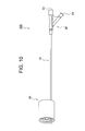
- the balloon catheter 200 of the present embodiment shown in FIGS. 9 to 14 is used for stent graft insertion as a treatment method for an aortic aneurysm.
- components denoted by the same reference numerals as those in FIGS. 1 to 8 are the same as those in the first embodiment, and the description thereof will be omitted.
- the balloon catheter 200 includes the catheter shaft 10, a hub 20 connected to the proximal end side of the catheter shaft 10, and a tubular balloon 30 having a smooth outer peripheral surface connected to the distal end side of the catheter shaft 10, The distal end portion of the catheter shaft 10 is inserted into the lumen of the balloon 30 while being in contact with the inner peripheral surface of the balloon 30 (the convex surface of the convex portion 334).
- the shaft 30A is in a twisted positional relationship.
- the distal end portion of the catheter shaft 10 contacts the inner peripheral surface of the balloon 30 (the convex surface of the convex portion 334) instead of the inside of the tube wall of the balloon 30 (a convex portion 334 described later).
- the balloon catheter 100 of the first embodiment is inserted into a lumen (lumen).
- the fluid from the expansion lumen 14 flows into the convex portion 334 of the balloon 30 in accordance with the position of the side hole 19 opened on the outer peripheral surface of the catheter shaft 10 (outer tube 13).
- a hole 39 is formed for the purpose.
- the fluid flowing through the expansion lumen 14 of the catheter shaft 10 and discharged to the outside of the catheter shaft 10 through the side hole 19 formed in the tube wall of the outer tube 13 passes through the hole 39 and the convex portion 334. (Inside the tube wall of the balloon 30).
- the fluid that has flowed into the protrusion 334 flows into the protrusions 331 to 333 and 335 to 338 through the front protrusion 31 or the rear protrusion 35.
- the balloon catheter 200 of the present embodiment when the balloon 30 is expanded inside the aneurysm and the stent graft is pressed against the inner wall of the aneurysm, sufficient blood flow to the periphery can be ensured.
- the balloon 30 has a high degree of roundness in the cross section, can uniformly develop a high expansion pressure in the circumferential direction, and can securely press the indwelling stent graft.
- the distal end of the catheter shaft 10 is inserted into the lumen of the balloon 30 while being in contact with the convex surface of the convex portion 334 extending in a direction inclined with respect to the tube axis direction of the balloon 30.
- the tube axis 30A of the balloon 30 has a twisted positional relationship, and the angle between them is 30 ° (corresponding to the inclination angle of the projection 334 with respect to the tube axis direction of the balloon 30).
- the base end edge of the flat balloon 30 after deflation can be in a state of being inclined with respect to an imaginary plane perpendicular to the central axis 10A of the catheter shaft 10 (inclination angle ⁇ 30 °).
- the present invention is not limited to these, and various deflections are possible.
- the number of protrusions arranged inside the balloon is not limited to eight as long as it is four or more.
- the number of convex portions is preferably 6 to 12.
- the angle of inclination of the convex portion with respect to the tube axis direction of the balloon is not limited to 30 °, and is usually 45 ° or less, and is preferably 45 ° or less. 15 to 30 °. If the inclination angle exceeds 45 °, the proximal end of the balloon is likely to be caught in the opening of the guiding catheter, and it is difficult to smoothly perform the balloon retraction operation.
- the distal end portion of the catheter shaft 10 that passes through the inside of the convex portion 334 of the balloon 30 has an intermediate region (a region located inside the convex portion 334).
- the outer tube 13 in ()) may be partially removed and may be formed only of the inner tube 11.
Landscapes
- Health & Medical Sciences (AREA)
- Heart & Thoracic Surgery (AREA)
- Engineering & Computer Science (AREA)
- Biomedical Technology (AREA)
- Life Sciences & Earth Sciences (AREA)
- Veterinary Medicine (AREA)
- Animal Behavior & Ethology (AREA)
- Public Health (AREA)
- General Health & Medical Sciences (AREA)
- Cardiology (AREA)
- Oral & Maxillofacial Surgery (AREA)
- Vascular Medicine (AREA)
- Transplantation (AREA)
- Child & Adolescent Psychology (AREA)
- Biophysics (AREA)
- Pulmonology (AREA)
- Anesthesiology (AREA)
- Hematology (AREA)
- Media Introduction/Drainage Providing Device (AREA)
Abstract
La présente invention vise à proposer un cathéter à ballonnet au moyen duquel l'écoulement sanguin vers les périphéries peut être suffisamment sécurisé lorsqu'un ballonnet est dilaté à l'intérieur d'un anévrisme, et une opération pour faire revenir un ballonnet contracté vers une lumière d'un cathéter de guidage peut être réalisée avec aisance. Un cathéter à ballonnet (100) selon la présente invention comporte : un arbre (10) ayant une lumière extensible (14); un embout (20) relié au côté extrémité de base de l'arbre (10); et un ballonnet tubulaire (30) relié au côté extrémité distale de l'arbre (10) et ayant une surface périphérique externe lisse, la section d'extrémité distale de l'arbre (10) étant introduite dans une section de saillie (224) qui est formée sur la périphérie interne du ballonnet (30) de façon à être inclinée par rapport à la direction de l'axe du tube, et l'axe central (10A) de l'arbre (10) étant situé à une position torsadée par rapport à l'axe du tube (30A) du ballonnet, et formant un angle ne dépassant pas 45° avec l'axe du tube (30A).
Priority Applications (2)
| Application Number | Priority Date | Filing Date | Title |
|---|---|---|---|
| JP2020526762A JP6847567B2 (ja) | 2018-06-26 | 2018-06-26 | バルーンカテーテル |
| PCT/JP2018/024255 WO2020003389A1 (fr) | 2018-06-26 | 2018-06-26 | Cathéter à ballonnet |
Applications Claiming Priority (1)
| Application Number | Priority Date | Filing Date | Title |
|---|---|---|---|
| PCT/JP2018/024255 WO2020003389A1 (fr) | 2018-06-26 | 2018-06-26 | Cathéter à ballonnet |
Publications (1)
| Publication Number | Publication Date |
|---|---|
| WO2020003389A1 true WO2020003389A1 (fr) | 2020-01-02 |
Family
ID=68986896
Family Applications (1)
| Application Number | Title | Priority Date | Filing Date |
|---|---|---|---|
| PCT/JP2018/024255 Ceased WO2020003389A1 (fr) | 2018-06-26 | 2018-06-26 | Cathéter à ballonnet |
Country Status (2)
| Country | Link |
|---|---|
| JP (1) | JP6847567B2 (fr) |
| WO (1) | WO2020003389A1 (fr) |
Cited By (1)
| Publication number | Priority date | Publication date | Assignee | Title |
|---|---|---|---|---|
| CN120585402A (zh) * | 2025-05-19 | 2025-09-05 | 上海心玮医疗科技股份有限公司 | 一种动脉瘤栓塞辅助装置 |
Citations (6)
| Publication number | Priority date | Publication date | Assignee | Title |
|---|---|---|---|---|
| JPH05184681A (ja) * | 1991-08-02 | 1993-07-27 | Scimed Life Syst Inc | 薬剤供給カテーテル及び薬剤供給方法 |
| JP2001061968A (ja) * | 1999-08-30 | 2001-03-13 | Hiroshi Terai | 動脈瘤治療具 |
| US20120109179A1 (en) * | 2009-04-15 | 2012-05-03 | Trinity College, Dublin University | Intravasculature Devices and Balloons for Use Therewith |
| JP2013223663A (ja) * | 2012-04-23 | 2013-10-31 | Terumo Corp | バルーンカテーテル用保護スリーブ、バルーンカテーテルシステムおよびステントデリバリーシステム |
| WO2014138404A1 (fr) * | 2013-03-07 | 2014-09-12 | Merit Medical Systems, Inc. | Ballonnet à filtre anti-embolie |
| WO2018135195A1 (fr) * | 2017-01-19 | 2018-07-26 | 日本ライフライン株式会社 | Cathéter à ballonnet |
-
2018
- 2018-06-26 WO PCT/JP2018/024255 patent/WO2020003389A1/fr not_active Ceased
- 2018-06-26 JP JP2020526762A patent/JP6847567B2/ja active Active
Patent Citations (6)
| Publication number | Priority date | Publication date | Assignee | Title |
|---|---|---|---|---|
| JPH05184681A (ja) * | 1991-08-02 | 1993-07-27 | Scimed Life Syst Inc | 薬剤供給カテーテル及び薬剤供給方法 |
| JP2001061968A (ja) * | 1999-08-30 | 2001-03-13 | Hiroshi Terai | 動脈瘤治療具 |
| US20120109179A1 (en) * | 2009-04-15 | 2012-05-03 | Trinity College, Dublin University | Intravasculature Devices and Balloons for Use Therewith |
| JP2013223663A (ja) * | 2012-04-23 | 2013-10-31 | Terumo Corp | バルーンカテーテル用保護スリーブ、バルーンカテーテルシステムおよびステントデリバリーシステム |
| WO2014138404A1 (fr) * | 2013-03-07 | 2014-09-12 | Merit Medical Systems, Inc. | Ballonnet à filtre anti-embolie |
| WO2018135195A1 (fr) * | 2017-01-19 | 2018-07-26 | 日本ライフライン株式会社 | Cathéter à ballonnet |
Cited By (1)
| Publication number | Priority date | Publication date | Assignee | Title |
|---|---|---|---|---|
| CN120585402A (zh) * | 2025-05-19 | 2025-09-05 | 上海心玮医疗科技股份有限公司 | 一种动脉瘤栓塞辅助装置 |
Also Published As
| Publication number | Publication date |
|---|---|
| JPWO2020003389A1 (ja) | 2020-12-17 |
| JP6847567B2 (ja) | 2021-03-24 |
Similar Documents
| Publication | Publication Date | Title |
|---|---|---|
| CN104853696B (zh) | 加强的可胀大的医疗装置 | |
| US6024737A (en) | Stent crimping device | |
| US9717615B2 (en) | Double layered balloons in medical devices | |
| JP2006502799A (ja) | 有利なコーンデザインを持つカテーテルバルーン | |
| JP6348486B2 (ja) | バルーンカテーテル、およびバルーンカテーテルの製造方法 | |
| US5944735A (en) | Process for stent compression | |
| US20020183769A1 (en) | Medical grafting methods and apparatus | |
| EP1152711A1 (fr) | Systeme de pose d'extenseur pour bifurcation | |
| JP2004504111A (ja) | 拡張術およびステント術用の補剛バルーン・カテーテル | |
| US20170296795A1 (en) | Balloon catheter visualization device including reinforcement features | |
| CN111772876A (zh) | 一种囊泡式串型瓣膜用扩张球囊 | |
| WO2017159688A1 (fr) | Cathéter à ballonnet, et procédé de production d'un élément allongé pour cathéter à ballonnet | |
| CN101198369B (zh) | 囊导管 | |
| JP6731691B2 (ja) | オクルージョンバルーンカテーテル | |
| EP1753497B1 (fr) | Ballon plié pour cathéter | |
| JP6847567B2 (ja) | バルーンカテーテル | |
| CN111374813B (zh) | 支架输送装置和支架装载方法 | |
| CN215690916U (zh) | 一种球形和柱形一体式气囊 | |
| JP6378979B2 (ja) | 拡張デバイス | |
| JP5947716B2 (ja) | ステントデリバリーシステムの製造方法 | |
| CN215653320U (zh) | 扩张球囊及球囊扩张导管 | |
| US20230397988A1 (en) | Balloon expandable transcatheter valve delivery devices and methods | |
| JP6488133B2 (ja) | バルーン | |
| JP2025140056A (ja) | ステントデリバリーシステムの製造方法 | |
| WO2008021555A1 (fr) | Ballonnet pour élément d'endoprothèse |
Legal Events
| Date | Code | Title | Description |
|---|---|---|---|
| 121 | Ep: the epo has been informed by wipo that ep was designated in this application |
Ref document number: 18924917 Country of ref document: EP Kind code of ref document: A1 |
|
| ENP | Entry into the national phase |
Ref document number: 2020526762 Country of ref document: JP Kind code of ref document: A |
|
| NENP | Non-entry into the national phase |
Ref country code: DE |
|
| 122 | Ep: pct application non-entry in european phase |
Ref document number: 18924917 Country of ref document: EP Kind code of ref document: A1 |