WO2020003389A1 - バルーンカテーテル - Google Patents
バルーンカテーテル Download PDFInfo
- Publication number
- WO2020003389A1 WO2020003389A1 PCT/JP2018/024255 JP2018024255W WO2020003389A1 WO 2020003389 A1 WO2020003389 A1 WO 2020003389A1 JP 2018024255 W JP2018024255 W JP 2018024255W WO 2020003389 A1 WO2020003389 A1 WO 2020003389A1
- Authority
- WO
- WIPO (PCT)
- Prior art keywords
- balloon
- catheter
- catheter shaft
- lumen
- fluid
- Prior art date
- Legal status (The legal status is an assumption and is not a legal conclusion. Google has not performed a legal analysis and makes no representation as to the accuracy of the status listed.)
- Ceased
Links
Images








Classifications
-
- A—HUMAN NECESSITIES
- A61—MEDICAL OR VETERINARY SCIENCE; HYGIENE
- A61F—FILTERS IMPLANTABLE INTO BLOOD VESSELS; PROSTHESES; DEVICES PROVIDING PATENCY TO, OR PREVENTING COLLAPSING OF, TUBULAR STRUCTURES OF THE BODY, e.g. STENTS; ORTHOPAEDIC, NURSING OR CONTRACEPTIVE DEVICES; FOMENTATION; TREATMENT OR PROTECTION OF EYES OR EARS; BANDAGES, DRESSINGS OR ABSORBENT PADS; FIRST-AID KITS
- A61F2/00—Filters implantable into blood vessels; Prostheses, i.e. artificial substitutes or replacements for parts of the body; Appliances for connecting them with the body; Devices providing patency to, or preventing collapsing of, tubular structures of the body, e.g. stents
- A61F2/95—Instruments specially adapted for placement or removal of stents or stent-grafts
- A61F2/958—Inflatable balloons for placing stents or stent-grafts
-
- A—HUMAN NECESSITIES
- A61—MEDICAL OR VETERINARY SCIENCE; HYGIENE
- A61M—DEVICES FOR INTRODUCING MEDIA INTO, OR ONTO, THE BODY; DEVICES FOR TRANSDUCING BODY MEDIA OR FOR TAKING MEDIA FROM THE BODY; DEVICES FOR PRODUCING OR ENDING SLEEP OR STUPOR
- A61M25/00—Catheters; Hollow probes
- A61M25/10—Balloon catheters
Definitions
- the present invention relates to a balloon catheter used for treating an aneurysm.
- stent graft insertion As a treatment for aortic aneurysms.
- indwelling stent grafts are usually crimped with an occlusion balloon catheter, and a balloon divided into three leaves is provided as such a balloon catheter.
- a Tri-Love balloon catheter has been introduced (see Non-Patent Document 1 below). According to the Tri-Love balloon catheter, even when the balloon is expanded in the aorta, it is said that a part of the peripheral blood flow can be maintained.
- the blood flow that can be secured from the gap between the three balloons constituting the Tri-Love balloon catheter is not sufficient. Further, the expansion force of these balloons is not sufficient to crimp the stent graft, and the crimping force of the three balloons on the stent graft varies in the circumferential direction.
- Patent Document 1 a bag-like material having elasticity is added to the distal end portion of a catheter, and this bag-like material is a flat film when no fluid is received therein.
- a dissociative aortic aneurysm treatment device which is tubular when fluid is received and in which the inner and outer membranes constituting the bag-like body are partially joined together has been proposed.
- the bag-like material (balloon) when the fluid is received inside becomes tubular, so that a sufficient blood flow to the periphery can be ensured.
- the expanding force of the bag-like material (substantially cylindrical balloon) at the time of receiving a fluid is not sufficient.
- the proximal end 2a of the bag-like material 2 (balloon) after contraction is perpendicular to the axial direction of the catheter 1 (catheter shaft).
- An object of the present invention is to provide a sufficient blood flow to the periphery when the balloon is expanded in the aneurysm, and to return the deflated balloon to a lumen such as a guiding catheter. Is to provide a balloon catheter that can perform the operation smoothly. It is another object of the present invention to provide a balloon catheter having a high roundness in a cross section and capable of uniformly generating a high expansion pressure in a circumferential direction.
- a balloon catheter includes a catheter shaft having a lumen (hereinafter, referred to as an “expansion lumen”) for flowing a fluid, a hub connected to a proximal end side of the catheter shaft, and the catheter.
- a tubular balloon connected to the distal end side of the shaft, The distal end portion of the catheter shaft is inserted into the lumen of the balloon while in contact with the inner wall surface of the balloon, or the inner wall surface of the balloon,
- a central axis of the catheter shaft is located at a position twisted with a tube axis of the balloon, and an angle between the catheter shaft and the tube axis is 45 ° or less.
- the “balloon tube wall” refers to a portion surrounding the lumen of the balloon, and includes a space (for example, the inside of a convex portion described later) sandwiched between the outer peripheral surface and the inner peripheral surface of the balloon.
- an angle between the central axis of the catheter shaft and the tube axis of the balloon is 15 to 30 °.
- the angle between the central axis of the catheter shaft and the tube axis of the balloon refers to the angle between a vector extending in the distal direction on the central axis and a vector extending in the distal direction on the tube axis.
- the stent graft placed in the aneurysm can be pressed against the inner wall surface of the aneurysm, and the blood flow to the periphery can be reduced. It can be sufficiently secured. Further, the distal end portion of the catheter shaft is inserted into the lumen of the balloon while being in contact with the inner wall surface of the balloon or the inner wall surface of the balloon, and the center axis of the catheter shaft and the tube axis of the balloon are aligned.
- the proximal end edge of the deflated balloon can be inclined with respect to an imaginary plane perpendicular to the central axis of the catheter shaft,
- this balloon is pulled back to the lumen of a guiding catheter or the like so as to be wrapped around a catheter shaft, the balloon can be smoothly pulled back without the proximal end of the balloon getting caught in the opening of the guiding catheter or the like. it can.
- the balloon preferably has a smooth outer peripheral surface. According to the balloon catheter having such a configuration, the stent graft placed in the aneurysm can be surely crimped by fitting it to the inner wall surface of the aneurysm.
- the inner periphery of the balloon is formed so as to extend obliquely with respect to the tube axis direction, and has convex portions having the same shape capable of accommodating a fluid therein. At least four are arranged along the direction, The insides of the protrusions communicate with each other, When the fluid supplied from the expansion lumen of the catheter shaft flows into the inside, each of the convex portions expands, and the adjacent convex portions come into contact with each other and press each other, whereby the Preferably, the balloon is inflated.
- the number of convex portions arranged on the inner periphery of the balloon is preferably 6 to 12, and particularly preferably 8.
- the balloon catheter having such a configuration, the balloon is expanded by expanding and pressing each other on the inner circumference of the balloon along the circumferential direction, so that the balloon expands.
- the catheter shaft is constituted by an inner tube having a guide wire lumen, and an outer tube forming the expansion lumen together with the inner tube.
- the distal end of the catheter shaft is inserted into any one of the protrusions (in the tube wall of the balloon), and the expansion is performed inside the protrusion.
- a fluid flowing through the working lumen is supplied.
- the fluid flowing through the expansion lumen is supplied to the inside of the convex portion through which the distal end portion of the catheter shaft is inserted, through the side hole formed in the tube wall of the outer tube.
- the fluid can be supplied to the inside of another protrusion communicating with the protrusion.
- the distal end of the catheter shaft is inserted into the lumen of the balloon while being in contact with any one of the convex surfaces of the convex portion. Further, a fluid flowing through the expansion lumen may be supplied.
- the fluid flowing through the expansion lumen is passed through the communication hole that communicates between the expansion lumen and the inside of the projection to the inside of the projection where the distal end of the outer tube is in contact.
- the fluid can also be supplied to the inside of another convex portion communicating with the convex portion.
- the convex surface of the convex portion is formed substantially flat.
- the blood flow to the periphery can be further secured, and the force when each of the protrusions expands and presses each other, and hence the expansion force of the balloon, is reduced. Can be increased.
- a distal end protruding portion which is capable of accommodating a fluid therein and has a height lower than the protruding portion is formed in the inner periphery of the distal end portion of the balloon along the circumferential direction. It is formed so as to extend, the inside of the tip protrusion communicates with the inside of each of the protrusions via a narrow channel,
- a rear end protruding portion capable of containing a fluid therein and having a height lower than the protruding portion is formed so as to extend along a circumferential direction, and the rear end protruding portion is formed.
- the inside of the portion communicates with the inside of each of the protrusions via a narrow channel, It is preferable that the insides of the protrusions communicate with each other.
- the distal end portion and the rear end portion of the balloon are formed such that the distal end convex portion and the rear end convex portion having a height lower than the convex portion are formed so as to extend along the circumferential direction.
- the balloon can be expanded without deforming or over-expanding the end portion, and the roundness of the cross section at the front end portion and the rear end portion of the balloon at the time of expansion becomes high.
- the balloon catheter of the present invention is suitably used for treating an aneurysm by stent graft insertion.
- the balloon catheter of this invention when the balloon which comprises this is expanded in an aneurysm, the blood flow to the periphery can be fully ensured, and the balloon in the contracted state is used as the guiding catheter. Such operations as pulling back to the lumen can be performed smoothly. Further, according to the balloon catheter of the above (3), the roundness of the cross section is high, and a high expansion pressure can be uniformly developed in the circumferential direction.
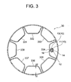
- FIG. 3 is a sectional view taken along the line III-III of FIG. 1.
- FIG. 4 is a sectional view taken along line IV-IV of FIG. 1.
- FIG. 5 is a sectional view taken along line VV of FIG. 1.
- FIG. 2 is a view showing a state where a balloon is deployed in the balloon catheter shown in FIG.
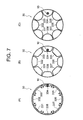
- FIG. 2 is a cross-sectional view showing a state where each of the convex portions of the balloon is expanded by the inflow of a fluid in the balloon catheter shown in FIG. 1.
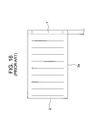
- FIG. 2 is an explanatory view schematically showing the shape of a balloon in a contracted state, which is pulled back to the lumen of the guiding catheter in the balloon catheter shown in FIG. 1.
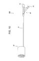
- FIG. 10 is a plan view of the balloon catheter shown in FIG. 9.
- FIG. 10 is a sectional view taken along the line XI-XI in FIG. 9.
- FIG. 12 is a sectional view taken along the line XII-XII in FIG. 9.
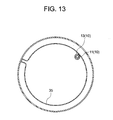
- FIG. 10 is a sectional view taken along line XIII-XIII in FIG. 9.
- FIG. 10 is a view showing a state where a balloon is deployed in the balloon catheter shown in FIG. 9.
- It is explanatory drawing which shows the connection state of a catheter shaft and a balloon in the conventional balloon catheter.
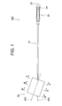
- the balloon catheter 100 of the present embodiment shown in FIGS. 1 to 8 is used for stent graft insertion as a treatment for an aortic aneurysm.
- the balloon catheter 100 includes a catheter shaft 10, a hub 20 connected to a proximal end side of the catheter shaft 10, and a tubular balloon 30 having a smooth outer peripheral surface connected to a distal end side of the catheter shaft 10,
- the distal end portion of the catheter shaft 10 is inserted into the tube wall of the balloon 30 (the inside of a convex portion 334 described later), and the central axis 10A of the catheter shaft 10 and the tube axis 30A of the balloon 30 are in a twisted positional relationship. is there.
- the catheter shaft 10 constituting the balloon catheter 100 is a double-tube shaft composed of an inner tube 11 and an outer tube 13.
- a guide wire lumen 12 for inserting a guide wire is formed in the inner tube 11.
- the outer peripheral surface of the inner tube 11 and the inner peripheral surface of the outer tube 13 form an expansion lumen 14 for flowing a fluid.
- a side hole 19 penetrating through the tube wall of the outer tube 13 and opening to the outer peripheral surface is formed, and the fluid flowing through the expansion lumen 14 passes through the side hole 19, It is discharged outside the catheter shaft 10.
- physiological saline can be exemplified.
- the inner diameter of the inner tube 11 is preferably 0.5 to 1.1 mm, and is 0.95 mm as a preferable example.
- the outer diameter of the inner tube 11 is preferably 0.7 to 1.3 mm, and is 1.15 mm as a preferred example.
- Suitable materials for forming the inner tube 11 include PEEK, PEBAX, polyurethane and nylon.
- the inner diameter of the outer tube 13 is preferably 0.8 to 3.8 mm, and is 1.8 mm as a preferred example.
- the outer diameter of the outer tube 13 (the outer diameter of the catheter shaft 10) is preferably 2 to 5 mm, and is 3 mm in a preferred example.
- Suitable materials for forming the outer tube 13 include PEBAX, polyurethane and nylon.
- a hub 20 is connected to the proximal end side of the catheter shaft 10.
- the hub 20 constituting the balloon catheter 100 is provided with a guide wire port 22 that is an opening of the guide wire lumen 12 of the catheter shaft 10 and an inflation port 24 that is an opening of the expansion lumen 14.
- a balloon 30 is connected to the distal end side of the catheter shaft 10.
- the balloon 30 that constitutes the balloon catheter 100 is a tubular balloon having a smooth outer peripheral surface without irregularities.
- a stent graft placed in the aneurysm is crimped to the inner wall surface of the aneurysm. And a sufficient blood flow to the periphery can be ensured.
- the outer periphery of the balloon 30 is formed with a smooth surface without irregularities. Thereby, the stent graft crimped by the balloon 30 can be fitted to the inner wall surface of the aneurysm.
- the outer diameter of the balloon 30 is preferably 20 to 40 mm, and a preferable example is 32 mm.
- convex portions 331 to 338 having the same shape as each other are formed so as to extend in a direction inclined by 30 ° with respect to the tube axis direction. They are arranged at 45 ° intervals along the direction.
- Each of the protrusions 331 to 338 is a so-called small balloon that expands by containing a fluid therein.
- the convex surfaces of the convex portions 331 to 338 are formed substantially flat. Thereby, the blood flow to the periphery when the balloon 30 is expanded can be increased more than the convex portion having a convex convex surface (the convex portion having a semi-cylindrical shape), and each of the convex portions 331 to 338 can be increased.
- the force when expanding and pressing each other, and in turn, the expanding force of the balloon 30 can be increased.
- the thickness (t 1 ) on the outer peripheral side of the balloon 30 is preferably 50 to 180 ⁇ m, and is 120 ⁇ m as a preferable example.
- the thickness (t 1 ) on the outer peripheral side is too small, the outer periphery of the balloon at the time of inflation is partially overinflated and the circularity of the cross section is impaired, and the expanding force is uniform in the circumferential direction. May not be able to be expressed.
- the film thickness (t 1 ) is excessively large, it may be difficult to form the balloon into a tubular shape, or the balloon may not be sufficiently expanded.
- the film thickness (t 2 ) on the inner peripheral side of the balloon 30 is preferably 50 to 180 ⁇ m, and is 120 ⁇ m as a preferable example. If the film thickness (t 2 ) on the inner circumference side is too small, the inner circumference of the balloon at the time of inflation is partially over-inflated, impairing the circularity of the cross section, and uniforming in the circumferential direction. In some cases, the expansion force cannot be developed. On the other hand, when the film thickness (t 2 ) is excessively large, it becomes difficult to form the balloon into a tubular shape, or the expansion of the convex portion is suppressed, so that the balloon can be sufficiently expanded. Or not.
- the ratio (t 1 / t 2 ) of the film thickness (t 1 ) on the outer peripheral side and the film thickness (t 2 ) on the inner peripheral side in the portion where the projections 331 to 338 are formed is 0.1 to 3.0. It is preferable to set it to 1.0 if a suitable example is shown. When the ratio (t 1 / t 2 ) is 0.1 or more, a higher expansion pressure (compression resistance) can be uniformly developed in the circumferential direction. In addition, when the ratio (t 1 / t 2 ) is 3.0 or less, overexpansion and the like at the inner periphery can be prevented.
- a distal convex portion 31 having a lower height than the convex portions 331 to 338 is provided on the inner periphery of the distal end portion of the balloon 30 (on the distal end side of the position where the convex portions 331 to 338 are formed). It is formed to extend along the circumferential direction.
- the tip convex portion 31 can accommodate a fluid therein, and expands when the fluid flows therein.
- the inside of the tip projection 31 communicates with each of the projections 331 to 338 via narrow channels 321 to 328.
- a rear end convex portion 35 (having the same height as the portion 31) is formed so as to extend along the circumferential direction.
- the rear end convex portion 35 can accommodate a fluid therein, and expands when the fluid flows therein.
- the inside of the rear end convex portion 35 communicates with each of the convex portions 331 to 338 via narrow channels 341 to 348.
- the insides of the protrusions 331 to 338 communicate with each other assuming that the front end protrusion 31 is a communication passage on the front end side and the rear end protrusion 35 is a communication passage on the rear end side.
- the balloon 30 can be expanded without causing deformation or excessive inflation at the distal end and the rear end of the balloon 30, and the true shape at the distal end and the rear end of the balloon 30 at the time of expansion can be obtained.
- the roundness is also high.
- the same resin material as that of a balloon constituting a conventionally known balloon catheter can be used, and a preferable material is polyurethane.
- the distal end portion of the catheter shaft 10 is inserted into the convex portion 334 constituting the tube wall of the balloon 30.
- the distal end portion of the catheter shaft 10 is completely sealed at the distal end portion and the rear end portion of the balloon 30 by the constituent material of the balloon 30, whereby the inside of the convex portion 334 has airtightness and liquid tightness. Is secured.
- the fluid that flows through the expansion lumen 14 of the catheter shaft 10 and is discharged to the outside through the side hole 19 formed in the tube wall of the outer tube 13 is a convex through which the distal end of the catheter shaft 10 is inserted. It is supplied to the inside of the part 334 (inside the tube wall of the balloon 30). Next, the fluid that has flowed into the inside of the convex portion 334 flows into the other convex portions (the convex portions 331 to 333 and 335 to 338) through the front convex portion 31 or the rear convex portion 35.
- the balloon 30 is formed by laminating a smooth first resin sheet and a completed second resin sheet (a region where the convex portion of the sheet is not formed) after completion, as shown in FIG.
- a laminated sheet having such a fluid accommodating space is prepared, and both sides of the obtained laminated sheet are bonded to each other so that the first resin sheet is positioned on the outer peripheral side and processed into a tubular (tubular) shape. can do.
- the tip of the catheter shaft 10 is positioned inside the projection 334 formed.
- FIG. 7 is a cross-sectional view of the balloon 30 showing a state where each of the protrusions 331 to 338 expands due to the inflow of the fluid.
- FIG. 7A shows a state before the fluid flows into the inside of the protrusions 331 to 338.
- B shows a state where the fluid flows into each of them and the convex portions 331 to 338 expand, but the adjacent convex portions are not in contact with each other
- C shows a state where the convex portions 331 to 338 are not in contact with each other. The state is further expanded so that adjacent convex portions are in contact with each other and press each other.
- the convex portions 331 to 338 are expanded in a state in which the balloon 30 is housed in a tube (not shown) that suppresses expansion of the balloon 30 (a tube simulating a blood vessel). Although the outer diameter of the balloon 30 does not change, the pressing force (expansion pressure) on the inner peripheral surface of the tube is as shown in FIG.
- the balloon 30 that expands when the convex portions formed on the inner periphery of the balloon 30 press against each other has a high circularity of a cross section at the time of expansion (a shape close to a perfect cylinder). Also, the developed expansion force is sufficiently high and uniform. It is considered that the reason for this is that the forces of opposing each other make it less likely to be distorted by an external pressure, and that the protrusions having the same shape are evenly expanded.
- the balloon catheter 100 of the present embodiment when the balloon 30 is expanded within the aneurysm and the stent graft is pressed against the inner wall of the aneurysm, sufficient blood flow to the periphery can be ensured.
- the balloon 30 has a high degree of roundness in the cross section, can uniformly develop a high expansion pressure in the circumferential direction, and can securely press the indwelling stent graft.
- the central axis 10A of the catheter shaft 10 and the tube of the balloon 30 are connected.
- the axis 30A is in a twisted positional relationship, and the angle between them is 30 ° (corresponding to the angle of inclination of the projection 334 with respect to the tube axis direction of the balloon 30).
- the base end edge 38 of the planar balloon 30 after being deflated is inclined with respect to a virtual plane P perpendicular to the central axis 10A of the catheter shaft 10 (inclination angle ⁇ ). (30 °), as shown in FIG. 8B, when the balloon 30 is pulled back to the lumen of the guiding catheter 50 while being wound around the catheter shaft 10, the balloon is inserted into the opening of the guiding catheter 50. The proximal end of the balloon 30 does not get caught, and thus the balloon 30 can be smoothly pulled back.
- the balloon catheter 200 of the present embodiment shown in FIGS. 9 to 14 is used for stent graft insertion as a treatment method for an aortic aneurysm.
- components denoted by the same reference numerals as those in FIGS. 1 to 8 are the same as those in the first embodiment, and the description thereof will be omitted.
- the balloon catheter 200 includes the catheter shaft 10, a hub 20 connected to the proximal end side of the catheter shaft 10, and a tubular balloon 30 having a smooth outer peripheral surface connected to the distal end side of the catheter shaft 10, The distal end portion of the catheter shaft 10 is inserted into the lumen of the balloon 30 while being in contact with the inner peripheral surface of the balloon 30 (the convex surface of the convex portion 334).
- the shaft 30A is in a twisted positional relationship.
- the distal end portion of the catheter shaft 10 contacts the inner peripheral surface of the balloon 30 (the convex surface of the convex portion 334) instead of the inside of the tube wall of the balloon 30 (a convex portion 334 described later).
- the balloon catheter 100 of the first embodiment is inserted into a lumen (lumen).
- the fluid from the expansion lumen 14 flows into the convex portion 334 of the balloon 30 in accordance with the position of the side hole 19 opened on the outer peripheral surface of the catheter shaft 10 (outer tube 13).
- a hole 39 is formed for the purpose.
- the fluid flowing through the expansion lumen 14 of the catheter shaft 10 and discharged to the outside of the catheter shaft 10 through the side hole 19 formed in the tube wall of the outer tube 13 passes through the hole 39 and the convex portion 334. (Inside the tube wall of the balloon 30).
- the fluid that has flowed into the protrusion 334 flows into the protrusions 331 to 333 and 335 to 338 through the front protrusion 31 or the rear protrusion 35.
- the balloon catheter 200 of the present embodiment when the balloon 30 is expanded inside the aneurysm and the stent graft is pressed against the inner wall of the aneurysm, sufficient blood flow to the periphery can be ensured.
- the balloon 30 has a high degree of roundness in the cross section, can uniformly develop a high expansion pressure in the circumferential direction, and can securely press the indwelling stent graft.
- the distal end of the catheter shaft 10 is inserted into the lumen of the balloon 30 while being in contact with the convex surface of the convex portion 334 extending in a direction inclined with respect to the tube axis direction of the balloon 30.
- the tube axis 30A of the balloon 30 has a twisted positional relationship, and the angle between them is 30 ° (corresponding to the inclination angle of the projection 334 with respect to the tube axis direction of the balloon 30).
- the base end edge of the flat balloon 30 after deflation can be in a state of being inclined with respect to an imaginary plane perpendicular to the central axis 10A of the catheter shaft 10 (inclination angle ⁇ 30 °).
- the present invention is not limited to these, and various deflections are possible.
- the number of protrusions arranged inside the balloon is not limited to eight as long as it is four or more.
- the number of convex portions is preferably 6 to 12.
- the angle of inclination of the convex portion with respect to the tube axis direction of the balloon is not limited to 30 °, and is usually 45 ° or less, and is preferably 45 ° or less. 15 to 30 °. If the inclination angle exceeds 45 °, the proximal end of the balloon is likely to be caught in the opening of the guiding catheter, and it is difficult to smoothly perform the balloon retraction operation.
- the distal end portion of the catheter shaft 10 that passes through the inside of the convex portion 334 of the balloon 30 has an intermediate region (a region located inside the convex portion 334).
- the outer tube 13 in ()) may be partially removed and may be formed only of the inner tube 11.
Landscapes
- Health & Medical Sciences (AREA)
- Heart & Thoracic Surgery (AREA)
- Engineering & Computer Science (AREA)
- Biomedical Technology (AREA)
- Life Sciences & Earth Sciences (AREA)
- Veterinary Medicine (AREA)
- Animal Behavior & Ethology (AREA)
- Public Health (AREA)
- General Health & Medical Sciences (AREA)
- Cardiology (AREA)
- Oral & Maxillofacial Surgery (AREA)
- Vascular Medicine (AREA)
- Transplantation (AREA)
- Child & Adolescent Psychology (AREA)
- Biophysics (AREA)
- Pulmonology (AREA)
- Anesthesiology (AREA)
- Hematology (AREA)
- Media Introduction/Drainage Providing Device (AREA)
Abstract
動脈瘤内でのバルーンの拡張時に末梢への血流を十分に確保することができ、収縮状態のバルーンをガイディングカテーテルのルーメンに引き戻す操作をスムーズに行うことができるバルーンカテーテルの提供を目的とする。 本発明のバルーンカテーテル(100)は、拡張用ルーメン(14)を有するシャフト(10)と、シャフト(10)の基端側に接続されたハブ(20)と、シャフト(10)の先端側に接続された、円滑な外周面を有する管状のバルーン(30)とを備えてなり、シャフト(10)の先端部は、バルーン(30)の内周において管軸方向に対し傾斜して延びるように形成された凸部(334)の内部に挿通されており、シャフト(10)の中心軸(10A)は、バルーン(30)の管軸(30A)とねじれの位置にあり、管軸(30A)とのなす角度が45°以下である。
Description
本発明は、動脈瘤の治療に使用するバルーンカテーテルに関する。
近年、大動脈瘤の治療法としてステントグラフト内挿術が注目されている。
ステントグラフト内挿術においては、通常、エンドリークを回避することなどを目的として、留置したステントグラフトをオクルージョンバルーンカテーテルによって圧着することが行われており、かかるバルーンカテーテルとして3葉に分かれたバルーンを備えたTri-Lobeバルーンカテーテルが紹介されている(下記非特許文献1参照)。
このTri-Lobeバルーンカテーテルによれば、大動脈内でのバルーン拡張時にも、末梢への血流を一部維持できるとされる。
ステントグラフト内挿術においては、通常、エンドリークを回避することなどを目的として、留置したステントグラフトをオクルージョンバルーンカテーテルによって圧着することが行われており、かかるバルーンカテーテルとして3葉に分かれたバルーンを備えたTri-Lobeバルーンカテーテルが紹介されている(下記非特許文献1参照)。
このTri-Lobeバルーンカテーテルによれば、大動脈内でのバルーン拡張時にも、末梢への血流を一部維持できるとされる。
しかしながら、Tri-Lobeバルーンカテーテルを構成する3つのバルーンの隙間から確保できる血流は十分なものではない。
また、これらバルーンによる拡張力は、ステントグラフトを圧着させるためには十分とはいえず、しかも、3つのバルーンによるステントグラフトに対する圧着力は、円周方向のバラツキがある。
また、これらバルーンによる拡張力は、ステントグラフトを圧着させるためには十分とはいえず、しかも、3つのバルーンによるステントグラフトに対する圧着力は、円周方向のバラツキがある。
一方、下記の特許文献1には、カテーテルの先端部分に、伸縮性を有する袋状物を添設してなり、この袋状物が、その内部に流体を受け入れない時には平坦化された膜状であり、流体を受け入れた時には管状であって、この袋状物を構成する内側の膜状物と外側の膜状物とが部分的に接合せしめられている解離性大動脈瘤治療具が提案されている。
この治療具によれば、内部に流体を受け入れた時の袋状物(バルーン)は管状となるため、末梢への血流を十分に確保することができる。
この治療具によれば、内部に流体を受け入れた時の袋状物(バルーン)は管状となるため、末梢への血流を十分に確保することができる。
しかしながら、特許文献1に記載された治療具においても、流体を受け入れた時の袋状物(略円筒状のバルーン)による拡張力は十分とはいえない。
また、特許文献1に記載された治療具においては、図16に示すように、収縮後の袋状物2(バルーン)の基端縁2aがカテーテル1(カテーテルシャフト)の軸方向に対して直角になっているため、カテーテル1に巻き付けるようにしてこの袋状物2をガイディングカテーテルなどのルーメンに引き戻す際に、ガイディングカテーテルの開口に袋状物2の基端が引っ掛かりやすく、袋状物2の引き戻し操作が困難であるという問題もある。
また、特許文献1に記載された治療具においては、図16に示すように、収縮後の袋状物2(バルーン)の基端縁2aがカテーテル1(カテーテルシャフト)の軸方向に対して直角になっているため、カテーテル1に巻き付けるようにしてこの袋状物2をガイディングカテーテルなどのルーメンに引き戻す際に、ガイディングカテーテルの開口に袋状物2の基端が引っ掛かりやすく、袋状物2の引き戻し操作が困難であるという問題もある。
胸部動脈瘤に対するステントグラフト内挿術:適応と手技 人工臓器38巻1号 2009年
本発明は、以上のような事情に基いてなされたものである。
本発明の目的は、動脈瘤内でバルーンを拡張させたときに、末梢への血流を十分に確保することができるとともに、収縮させた状態のバルーンを、ガイディングカテーテルなどのルーメンに引き戻す操作をスムーズに行うことができるバルーンカテーテルを提供する
ことにある。
本発明の他の目的は、横断面の真円度が高く、高い拡張圧を円周方向に均一に発現させることができるバルーンカテーテルを提供することにある。
本発明の目的は、動脈瘤内でバルーンを拡張させたときに、末梢への血流を十分に確保することができるとともに、収縮させた状態のバルーンを、ガイディングカテーテルなどのルーメンに引き戻す操作をスムーズに行うことができるバルーンカテーテルを提供する
ことにある。
本発明の他の目的は、横断面の真円度が高く、高い拡張圧を円周方向に均一に発現させることができるバルーンカテーテルを提供することにある。
(1)本発明のバルーンカテーテルは、流体を流通させるためのルーメン(以下、「拡張用ルーメン」という。)を有するカテーテルシャフトと、前記カテーテルシャフトの基端側に接続されたハブと、前記カテーテルシャフトの先端側に接続された管状のバルーンとを備えてなり、
前記カテーテルシャフトの先端部は、前記バルーンの管壁内、または、前記バルーンの内周面と接触しながら当該バルーンの内腔に挿通されており、
前記カテーテルシャフトの中心軸は、前記バルーンの管軸とねじれの位置にあり、前記管軸とのなす角度が45°以下であることを特徴とする。
前記カテーテルシャフトの先端部は、前記バルーンの管壁内、または、前記バルーンの内周面と接触しながら当該バルーンの内腔に挿通されており、
前記カテーテルシャフトの中心軸は、前記バルーンの管軸とねじれの位置にあり、前記管軸とのなす角度が45°以下であることを特徴とする。
ここに、「バルーンの管壁」とは、バルーンの内腔を取り囲む部分をいい、バルーンの外周面と内周面とに挟まれた空間(例えば、後述する凸部の内部)を含む。
(2)本発明のバルーンカテーテルにおいて、前記カテーテルシャフトの前記中心軸と、前記バルーンの前記管軸とのなす角度が15~30°であることが好ましい。
ここに、カテーテルシャフトの中心軸とバルーンの管軸とのなす角度とは、前記中心軸上を先端方向に延びるベクトルと、前記管軸上を先端方向に延びるベクトルとのなす角度をいう。
上記のような構成のバルーンカテーテルによれば、これを構成するバルーンが管状であるため、動脈瘤内に留置したステントグラフトを動脈瘤の内壁面に圧着することができるとともに、末梢への血流を十分に確保することができる。
また、カテーテルシャフトの先端部が、バルーンの管壁内、または、バルーンの内周面と接触しながら当該バルーンの内腔に挿通されていて、カテーテルシャフトの中心軸と、バルーンの管軸とがねじれの位置関係にある(平行な位置関係にない)ことにより、収縮させたバルーンの基端縁を、カテーテルシャフトの中心軸に垂直な仮想平面に対して傾斜した状態とすることができるので、カテーテルシャフトに巻き付けるようにしてこのバルーンをガイディングカテーテルなどのルーメンに引き戻す際に、ガイディングカテーテルなどの開口にバルーンの基端が引っ掛かるようなことがなく、バルーンの引き戻し操作をスムーズに行うことができる。
また、カテーテルシャフトの先端部が、バルーンの管壁内、または、バルーンの内周面と接触しながら当該バルーンの内腔に挿通されていて、カテーテルシャフトの中心軸と、バルーンの管軸とがねじれの位置関係にある(平行な位置関係にない)ことにより、収縮させたバルーンの基端縁を、カテーテルシャフトの中心軸に垂直な仮想平面に対して傾斜した状態とすることができるので、カテーテルシャフトに巻き付けるようにしてこのバルーンをガイディングカテーテルなどのルーメンに引き戻す際に、ガイディングカテーテルなどの開口にバルーンの基端が引っ掛かるようなことがなく、バルーンの引き戻し操作をスムーズに行うことができる。
(3)本発明のバルーンカテーテルにおいて、前記バルーンは円滑な外周面を有していることが好ましい。
このような構成のバルーンカテーテルによれば、動脈瘤内に留置したステントグラフトを動脈瘤の内壁面に適合させて確実に圧着することができる。
このような構成のバルーンカテーテルによれば、動脈瘤内に留置したステントグラフトを動脈瘤の内壁面に適合させて確実に圧着することができる。
(4)本発明のバルーンカテーテルにおいて、前記バルーンの内周には、前記管軸方向に対し傾斜して延びるように形成され、内部に流体を収容可能な互いに同一形状の凸部が、円周方向に沿って少なくとも4本配置され、
前記凸部の内部どうしは互いに連通しており、
前記カテーテルシャフトの前記拡張用ルーメンから供給される流体が内部に流入されることで、前記凸部の各々が拡張し、隣り合う前記凸部どうしが接触して相互に押圧し合うことにより、前記バルーンが拡張することが好ましい。
ここに、前記バルーンの内周に配置された凸部の本数は6~12であることが好ましく、8であることが特に好ましい。
このような構成のバルーンカテーテルによれば、バルーンの内周において円周方向に沿って配置された凸部の各々が拡張して相互に押圧し合うことで当該バルーンが拡張するので、拡張するバルーンは、横断面の真円度が高く、従来公知のバルーンカテーテルを構成するバルーンよりも高い拡張圧を円周方向に均一に発現させることができる。
前記凸部の内部どうしは互いに連通しており、
前記カテーテルシャフトの前記拡張用ルーメンから供給される流体が内部に流入されることで、前記凸部の各々が拡張し、隣り合う前記凸部どうしが接触して相互に押圧し合うことにより、前記バルーンが拡張することが好ましい。
ここに、前記バルーンの内周に配置された凸部の本数は6~12であることが好ましく、8であることが特に好ましい。
このような構成のバルーンカテーテルによれば、バルーンの内周において円周方向に沿って配置された凸部の各々が拡張して相互に押圧し合うことで当該バルーンが拡張するので、拡張するバルーンは、横断面の真円度が高く、従来公知のバルーンカテーテルを構成するバルーンよりも高い拡張圧を円周方向に均一に発現させることができる。
(5)上記(4)のバルーンカテーテルにおいて、前記カテーテルシャフトは、ガイドワイヤルーメンを有するインナーチューブと、前記インナーチューブとともに、前記拡張用ルーメンを形成するアウターチューブとにより構成されていることが好ましい。
(6)上記(5)のバルーンカテーテルにおいて、前記カテーテルシャフトの先端部が、前記凸部の何れか1本の内部(バルーンの管壁内)に挿通され、この凸部の内部に、前記拡張用ルーメンを流通する流体が供給されることが好ましい。
このような構成のバルーンカテーテルによれば、アウターチューブの管壁に形成された側孔などを通して、拡張ルーメンを流通する流体を、カテーテルシャフトの先端部が挿通されている凸部の内部に供給することができ、さらに、この凸部と連通している他の凸部の内部にも流体を供給することができる。
(7)また、上記(5)のバルーンカテーテルにおいて、前記カテーテルシャフトの先端部が、前記凸部の何れか1本の凸面に接触しながら前記バルーンの内腔に挿通され、この凸部の内部に、前記拡張用ルーメンを流通する流体が供給されるものであってもよい。
このような構成のバルーンカテーテルによれば、拡張用ルーメンと凸部の内部とを連通する連通孔などを通して、拡張ルーメンを流通する流体を、アウターチューブの先端部が接触している凸部の内部に供給することができ、さらに、この凸部と連通している他の凸部の内部にも流体を供給することができる。
(8)上記(4)のバルーンカテーテルにおいて、前記凸部の凸面が略平坦に形成されていることが好ましい。
このような構成のバルーンカテーテルによれば、末梢への血流量を更に確保することができるとともに、凸部の各々が拡張して相互に押し合うときの力、延いては、バルーンの拡張力を増大させることができる。
(9)上記(4)のバルーンカテーテルにおいて、前記バルーンの先端部の内周には、内部に流体を収容可能で、前記凸部よりも高さの低い先端凸部が円周方向に沿って延びるように形成され、前記先端凸部の内部は、前記凸部の各々の内部と狭小流路を介して連通し、
前記バルーンの後端部の内周には、内部に流体を収容可能で、前記凸部よりも高さの低い後端凸部が円周方向に沿って延びるように形成され、前記後端凸部の内部は、前記凸部の各々の内部と狭小流路を介して連通していることにより、
前記凸部の内部どうしが互いに連通していることが好ましい。
前記バルーンの後端部の内周には、内部に流体を収容可能で、前記凸部よりも高さの低い後端凸部が円周方向に沿って延びるように形成され、前記後端凸部の内部は、前記凸部の各々の内部と狭小流路を介して連通していることにより、
前記凸部の内部どうしが互いに連通していることが好ましい。
このような構成のバルーンカテーテルによれば、凸部よりも高さの低い先端凸部および後端凸部が円周方向に沿って延びるように形成されていることにより、バルーンの先端部および後端部が変形や過膨張を起こすことなく当該バルーンを拡張させることができ、拡張時のバルーンの先端部および後端部における横断面の真円度も高いものとなる。
(10)本発明のバルーンカテーテルは、ステントグラフト内挿術による動脈瘤の治療に好適に使用される。
本発明のバルーンカテーテルによれば、これを構成するバルーンを動脈瘤内で拡張させたときに、末梢への血流を十分に確保することができるとともに、収縮させた状態のバルーンをガイディングカテーテルなどのルーメンに引き戻す操作をスムーズに行うことができる。
また、上記(3)のバルーンカテーテルによれば、横断面の真円度が高く、高い拡張圧を円周方向に均一に発現させることができる。
また、上記(3)のバルーンカテーテルによれば、横断面の真円度が高く、高い拡張圧を円周方向に均一に発現させることができる。
<第1実施形態>
図1~図8に示す本実施形態のバルーンカテーテル100は、大動脈瘤の治療法であるステントグラフト内挿術に使用される。
バルーンカテーテル100は、カテーテルシャフト10と、カテーテルシャフト10の基端側に接続されたハブ20と、カテーテルシャフト10の先端側に接続された、円滑な外周面を有する管状のバルーン30とを備え、カテーテルシャフト10の先端部が、バルーン30の管壁(後述する凸部334の内部)に挿通されており、カテーテルシャフト10の中心軸10Aと、バルーン30の管軸30Aとがねじれの位置関係にある。
図1~図8に示す本実施形態のバルーンカテーテル100は、大動脈瘤の治療法であるステントグラフト内挿術に使用される。
バルーンカテーテル100は、カテーテルシャフト10と、カテーテルシャフト10の基端側に接続されたハブ20と、カテーテルシャフト10の先端側に接続された、円滑な外周面を有する管状のバルーン30とを備え、カテーテルシャフト10の先端部が、バルーン30の管壁(後述する凸部334の内部)に挿通されており、カテーテルシャフト10の中心軸10Aと、バルーン30の管軸30Aとがねじれの位置関係にある。
図3~図5に示すように、バルーンカテーテル100を構成するカテーテルシャフト10は、インナーチューブ11とアウターチューブ13とからなる二重管構造のシャフトである。
図3に示すように、インナーチューブ11には、ガイドワイヤを挿通するためのガイドワイヤルーメン12が形成されている。
また、インナーチューブ11の外周面とアウターチューブ13の内周面とにより、流体
を流通させるための拡張用ルーメン14が形成されている。
また、インナーチューブ11の外周面とアウターチューブ13の内周面とにより、流体
を流通させるための拡張用ルーメン14が形成されている。
カテーテルシャフト10の先端部には、アウターチューブ13の管壁を貫通して外周面に開口する側孔19が形成されており、拡張用ルーメン14を流通する流体は、側孔19を通って、カテーテルシャフト10の外部に排出される。
ここに、流体としては生理食塩水を例示することができる。
ここに、流体としては生理食塩水を例示することができる。
インナーチューブ11の内径としては0.5~1.1mmであることが好ましく、好適な一例を示せば0.95mmである。
インナーチューブ11の外径としては0.7~1.3mmであることが好ましく、好適な一例を示せば1.15mmである。
インナーチューブ11を構成する好適な材料としては、PEEK、PEBAX、ポリウレタンおよびナイロンなどを挙げることができる。
インナーチューブ11の外径としては0.7~1.3mmであることが好ましく、好適な一例を示せば1.15mmである。
インナーチューブ11を構成する好適な材料としては、PEEK、PEBAX、ポリウレタンおよびナイロンなどを挙げることができる。
アウターチューブ13の内径としては0.8~3.8mmであることが好ましく、好適な一例を示せば1.8mmである。
アウターチューブ13の外径(カテーテルシャフト10の外径)としては2~5mmであることが好ましく、好適な一例を示せば3mmである。
アウターチューブ13を構成する好適な材料としては、PEBAX、ポリウレタンおよびナイロンなどを挙げることができる。
アウターチューブ13の外径(カテーテルシャフト10の外径)としては2~5mmであることが好ましく、好適な一例を示せば3mmである。
アウターチューブ13を構成する好適な材料としては、PEBAX、ポリウレタンおよびナイロンなどを挙げることができる。
カテーテルシャフト10の基端側にはハブ20が接続されている。
バルーンカテーテル100を構成するハブ20には、カテーテルシャフト10のガイドワイヤルーメン12の開口であるガイドワイヤポート22と、拡張用ルーメン14の開口であるインフレーションポート24とが設けられている。
バルーンカテーテル100を構成するハブ20には、カテーテルシャフト10のガイドワイヤルーメン12の開口であるガイドワイヤポート22と、拡張用ルーメン14の開口であるインフレーションポート24とが設けられている。
カテーテルシャフト10の先端側にはバルーン30が接続されている。
バルーンカテーテル100を構成するバルーン30は凹凸のない円滑な外周面を有する管状のバルーンであり、このバルーン30を拡張させることにより、動脈瘤内に留置したステントグラフトを、動脈瘤の内壁面に圧着することができるとともに、末梢への血流を十分に確保することができる。
バルーンカテーテル100を構成するバルーン30は凹凸のない円滑な外周面を有する管状のバルーンであり、このバルーン30を拡張させることにより、動脈瘤内に留置したステントグラフトを、動脈瘤の内壁面に圧着することができるとともに、末梢への血流を十分に確保することができる。
図3に示すように、バルーン30の外周は凹凸のない円滑面で形成されている。これにより、バルーン30によって圧着されるステントグラフトを動脈瘤の内壁面に適合させることができる。
ここに、バルーン30の外径としては20~40mmであることが好ましく、好適な一例を示せば32mmである。
ここに、バルーン30の外径としては20~40mmであることが好ましく、好適な一例を示せば32mmである。
図3および図6に示すように、バルーン30の内周には、その管軸方向に対して30°傾斜した方向に延びるように形成された、互いに同一形状の凸部331~338が円周方向に沿って45°間隔に配置されている。
凸部331~338は、各々の内部に流体を収容することで拡張するいわば小バルーンである。
凸部331~338の各々の凸面は略平坦に形成されている。これにより、バルーン30を拡張させたときの末梢への血流を、凸面が湾曲している凸部(蒲鉾状の凸部)よりも増加させることができるとともに、凸部331~338の各々が拡張して相互に押し合うときの力、延いては、バルーン30の拡張力を増大させることができる。
凸部331~338の各々の凸面は略平坦に形成されている。これにより、バルーン30を拡張させたときの末梢への血流を、凸面が湾曲している凸部(蒲鉾状の凸部)よりも増加させることができるとともに、凸部331~338の各々が拡張して相互に押し合うときの力、延いては、バルーン30の拡張力を増大させることができる。
凸部331~338の形成部分において、バルーン30の外周側の膜厚(t1 )として
は50~180μmであることが好ましく、好適な一例を示せば120μmとされる。
外周側の膜厚(t1 )が過小である場合には、拡張時におけるバルーンの外周が部分的に過膨張となって横断面の真円性が損なわれ、円周方向に均一な拡張力を発現させることができなくなることがある。一方、この膜厚(t1 )が過大である場合には、バルーンを管状に加工することが困難となったり、バルーンを十分に拡張させることができなかったりすることがある。
は50~180μmであることが好ましく、好適な一例を示せば120μmとされる。
外周側の膜厚(t1 )が過小である場合には、拡張時におけるバルーンの外周が部分的に過膨張となって横断面の真円性が損なわれ、円周方向に均一な拡張力を発現させることができなくなることがある。一方、この膜厚(t1 )が過大である場合には、バルーンを管状に加工することが困難となったり、バルーンを十分に拡張させることができなかったりすることがある。
バルーン30の内周側の膜厚(t2 )としては50~180μmであることが好ましく、好適な一例を示せば120μmとされる。
内周側の膜厚(t2 )が過小である場合には、拡張時におけるバルーンの内周が部分的に過膨張となって横断面の真円性が損なわれ、円周方向に均一な拡張力を発現させることができなくなることがある。一方、この膜厚(t2 )が過大である場合には、バルーンを管状に加工することが困難となったり、凸部の拡張が抑制されることにより、バルーンを十分に拡張させることができなかったりすることがある。
内周側の膜厚(t2 )が過小である場合には、拡張時におけるバルーンの内周が部分的に過膨張となって横断面の真円性が損なわれ、円周方向に均一な拡張力を発現させることができなくなることがある。一方、この膜厚(t2 )が過大である場合には、バルーンを管状に加工することが困難となったり、凸部の拡張が抑制されることにより、バルーンを十分に拡張させることができなかったりすることがある。
凸部331~338の形成部分における外周側の膜厚(t1 )と内周側の膜厚(t2 )との比率(t1 /t2 )としては0.1~3.0であることが好ましく、好適な一例を示せば1.0とされる。
この比率(t1 /t2 )が0.1以上であることにより、より高い拡張圧(圧縮抵抗)を円周方向に均一に発現させることができる。
また、比率(t1 /t2 )が3.0以下であることにより、内周における過膨張などを防止することができる。
この比率(t1 /t2 )が0.1以上であることにより、より高い拡張圧(圧縮抵抗)を円周方向に均一に発現させることができる。
また、比率(t1 /t2 )が3.0以下であることにより、内周における過膨張などを防止することができる。
図4および図6に示すように、バルーン30の先端部の内周(凸部331~338の形成位置の先端側)には、凸部331~338よりも高さの低い先端凸部31が円周方向に沿って延びるように形成されている。
先端凸部31は、その内部に流体を収容することができ、流体が流入されることにより拡張する。先端凸部31の内部は、狭小流路321~328を介して、凸部331~338の各々と連通している。
先端凸部31は、その内部に流体を収容することができ、流体が流入されることにより拡張する。先端凸部31の内部は、狭小流路321~328を介して、凸部331~338の各々と連通している。
図5および図6に示すように、バルーン30の後端部の内周(凸部331~338の形成位置の後端側)には、凸部331~338よりも高さの低い(先端凸部31と同一高さの)後端凸部35が円周方向に沿って延びるように形成されている。
後端凸部35は、その内部に流体を収容することができ、流体が流入されることにより拡張する。後端凸部35の内部は、狭小流路341~348を介して、凸部331~338の各々と連通している。
これにより、凸部331~338の内部どうしは、先端凸部31を先端側の連通流路とし、後端凸部35を後端側の連通流路として互いに連通している。
後端凸部35は、その内部に流体を収容することができ、流体が流入されることにより拡張する。後端凸部35の内部は、狭小流路341~348を介して、凸部331~338の各々と連通している。
これにより、凸部331~338の内部どうしは、先端凸部31を先端側の連通流路とし、後端凸部35を後端側の連通流路として互いに連通している。
このような構造によれば、バルーン30の先端部および後端部において変形や過膨張を起こすことなく当該バルーン30を拡張させることができ、拡張時のバルーン30の先端側および後端部における真円度も高いものとなる。
バルーン30の構成材料としては、従来公知のバルーンカテーテルを構成するバルーンと同一の樹脂材料を使用することができ、好適な材料としてポリウレタンを挙げることができる。
図3および図6に示すように、バルーン30の管壁を構成する凸部334の内部には、カテーテルシャフト10の先端部が挿通されている。
カテーテルシャフト10の先端部は、バルーン30の先端部および後端部において、バ
ルーン30の構成材料によって完全に封止されており、これにより、凸部334の内部は、気密性および液密性が確保されている。
カテーテルシャフト10の先端部は、バルーン30の先端部および後端部において、バ
ルーン30の構成材料によって完全に封止されており、これにより、凸部334の内部は、気密性および液密性が確保されている。
これにより、カテーテルシャフト10の拡張ルーメン14を流通し、アウターチューブ13の管壁に形成された側孔19を通って外部に排出される流体は、カテーテルシャフト10の先端部が挿通されている凸部334の内部(バルーン30の管壁内)に供給される。
次いで、この凸部334の内部に流入した流体は、先端凸部31または後端凸部35を通って他の凸部(凸部331~333および335~338)に流入される。
次いで、この凸部334の内部に流入した流体は、先端凸部31または後端凸部35を通って他の凸部(凸部331~333および335~338)に流入される。
バルーン30は、平滑な第1の樹脂シートと、完成後の内周側形状に成形された第2の樹脂シート(当該シートの凸部を形成しない領域)とを貼り合わせ、図6に示したような、流体の収容空間を有する積層シートを作製し、得られた積層シートの両側を、第1の樹脂シートが外周側に位置するよう貼り合わせて管状(筒状)に加工することにより製造することができる。
なお、第1の樹脂シートと第2の樹脂シートを貼り合わせるとき、形成される凸部334の内部にカテーテルシャフト10の先端部が位置するようにする。
なお、第1の樹脂シートと第2の樹脂シートを貼り合わせるとき、形成される凸部334の内部にカテーテルシャフト10の先端部が位置するようにする。
この実施形態のバルーンカテーテル100において、カテーテルシャフト10の拡張用ルーメン14から流体が流入されて凸部331~338の各々が拡張することにより、隣り合う凸部どうしが接触して相互に押圧し合い、これにより、バルーン30を、その径方向に押し広げようとする強い拡張力が発現する。
図7は、流体の流入によって凸部331~338の各々が拡張する状態を示すバルーン30の横断面図であり、(A)は、凸部331~338の内部に流体を流入する前の状態、(B)は、各々の内部に流体が流入されて凸部331~338が拡張しているが、隣り合う凸部どうしが接触していない状態、(C)は、凸部331~338が更に拡張して、隣り合う凸部どうしが接触して相互に押圧し合っている状態である。
なお、図7(A)~(C)では、バルーン30の拡張を抑制する図示しないチューブ(血管を模擬したチューブ)にバルーン30を収容した状態で凸部331~338を拡張させているため、バルーン30の外径は変化していないが、チューブの内周面への押圧力(拡張圧)は、同図(A)<(B)<(C)となっている。
上記のように、バルーン30の内周に形成された凸部どうしが押圧し合うことによって拡張するバルーン30は、拡張時における横断面の真円度が高く(真円柱形に近い形状であり)、また、発現される拡張力は十分に高くて均一である。
その理由としては、互いに張り合う力が働くことで外部からの圧力に対して歪みにくくなり、また、互いに同一形状の凸部を用いることで均等に拡張されるからであると考えられる。
その理由としては、互いに張り合う力が働くことで外部からの圧力に対して歪みにくくなり、また、互いに同一形状の凸部を用いることで均等に拡張されるからであると考えられる。
本実施形態のバルーンカテーテル100によれば、動脈瘤内でバルーン30を拡張させてステントグラフトを動脈瘤の内壁に圧着させたときに、末梢への血流を十分に確保することができ、拡張時におけるバルーン30は、横断面の真円度が高く、高い拡張圧を円周方向に均一に発現させることができ、留置したステントグラフトを確実に圧着させることができる。
また、カテーテルシャフト10の先端部が、バルーン30の管軸方向に対して傾斜した方向に延びる凸部334の内部に挿通されていることにより、カテーテルシャフト10の中心軸10Aと、バルーン30の管軸30Aとがねじれの位置関係になり、両者のなす角
度は30°(バルーン30の管軸方向に対する凸部334の傾斜角度に一致する)となる。
度は30°(バルーン30の管軸方向に対する凸部334の傾斜角度に一致する)となる。
これにより、図8(A)に示すように、収縮後における平面状のバルーン30の基端縁38を、カテーテルシャフト10の中心軸10Aに垂直な仮想平面Pに対し傾斜した状態(傾斜角度θ≒30°)とすることができ、図8(B)に示すように、カテーテルシャフト10に巻き付けるようにしながらバルーン30をガイディングカテーテル50のルーメンに引き戻す際に、ガイディングカテーテル50の開口にバルーン30の基端が引っ掛かるようなことがなく、これにより、バルーン30の引き戻し操作をスムーズに行うことができる。
<第2実施形態>
図9~図14に示す本実施形態のバルーンカテーテル200は、大動脈瘤の治療法であるステントグラフト内挿術に使用される。
図9~図14において、図1~図8と同一符号で示す構成要素は、第1実施形態と同一の構成要素であり、その説明を省略する。
図9~図14に示す本実施形態のバルーンカテーテル200は、大動脈瘤の治療法であるステントグラフト内挿術に使用される。
図9~図14において、図1~図8と同一符号で示す構成要素は、第1実施形態と同一の構成要素であり、その説明を省略する。
バルーンカテーテル200は、カテーテルシャフト10と、カテーテルシャフト10の基端側に接続されたハブ20と、カテーテルシャフト10の先端側に接続された、円滑な外周面を有する管状のバルーン30とを備え、カテーテルシャフト10の先端部が、バルーン30の内周面(凸部334の凸面)と接触しながら当該バルーン30の内腔に挿通されており、カテーテルシャフト10の中心軸10Aと、バルーン30の管軸30Aとがねじれの位置関係にある。
バルーンカテーテル200は、カテーテルシャフト10の先端部が、バルーン30の管壁(後述する凸部334)の内部ではなく、バルーン30の内周面(凸部334の凸面)と接触しながら当該バルーン30の内腔(ルーメン)に挿通されている点で、第1実施形態のバルーンカテーテル100と異なっている。
図11に示すように、バルーン30の凸部334には、カテーテルシャフト10(アウターチューブ13)の外周面に開口する側孔19の位置に合わせて、拡張用ルーメン14からの流体を内部に流入させるための孔39が形成されている。
これにより、カテーテルシャフト10の拡張ルーメン14を流通し、アウターチューブ13の管壁に形成された側孔19を通ってカテーテルシャフト10の外部に排出される流体は、孔39を通って凸部334の内部(バルーン30の管壁内)に供給される。
次いで、この凸部334の内部に流入した流体は、先端凸部31または後端凸部35を通って、凸部331~333および335~338に流入される。
次いで、この凸部334の内部に流入した流体は、先端凸部31または後端凸部35を通って、凸部331~333および335~338に流入される。
本実施形態のバルーンカテーテル200によれば、動脈瘤内でバルーン30を拡張させてステントグラフトを動脈瘤の内壁に圧着させたときに、末梢への血流を十分に確保することができ、拡張時におけるバルーン30は、横断面の真円度が高く、高い拡張圧を円周方向に均一に発現させることができ、留置したステントグラフトを確実に圧着させることができる。
また、カテーテルシャフト10の先端部が、バルーン30の管軸方向に対して傾斜した方向に延びる凸部334の凸面と接触しながら当該バルーン30の内腔に挿通されていることにより、カテーテルシャフト10の中心軸10Aと、バルーン30の管軸30Aとがねじれの位置関係になり、両者のなす角度は30°(バルーン30の管軸方向に対する凸部334の傾斜角度に一致する)となる。
これにより、収縮後における平面状のバルーン30の基端縁を、カテーテルシャフト10の中心軸10Aに垂直な仮想平面に対し傾斜した状態(傾斜角度≒30°)とすることができ、カテーテルシャフト10に巻き付けるようにしながらバルーン30をガイディングカテーテルのルーメンに引き戻す際に、当該ガイディングカテーテルの開口にバルーン30の基端が引っ掛かるようなことがなく、これにより、バルーン30の引き戻し操作をスムーズに行うことができる。
以上、本発明の一実施形態について説明したが、本発明はこれらに限定されるものではなく、種々の偏向が可能である。
例えば、バルーンの内部に配置される凸部は、4本以上であれば8本に限定されるものでない。但し、凸部の本数が増加するに伴って拡張力が低下する傾向があるため、凸部の本数としては6~12本であることが好ましい。
例えば、バルーンの内部に配置される凸部は、4本以上であれば8本に限定されるものでない。但し、凸部の本数が増加するに伴って拡張力が低下する傾向があるため、凸部の本数としては6~12本であることが好ましい。
また、バルーンの管軸方向に対する凸部の傾斜角度(カテーテルシャフトの中心軸と、バルーンの管軸とのなす角度)は30°に限定されるものでなく、通常45°以下とされ、好ましくは15~30°とされる。
この傾斜角度が45°を越えると、ガイディングカテーテルの開口にバルーンの基端が引っ掛かりやすくなり、バルーンの引き戻し操作をスムーズに行うことが困難になる。
この傾斜角度が45°を越えると、ガイディングカテーテルの開口にバルーンの基端が引っ掛かりやすくなり、バルーンの引き戻し操作をスムーズに行うことが困難になる。
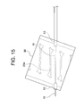
また、第1実施形態の変形例として、図15に示すように、バルーン30の凸部334の内部を挿通するカテーテルシャフト10の先端部について、その中間領域(凸部334の内部に位置する領域)におけるアウターチューブ13の一部が除去されてインナーチューブ11のみからなるものであってもよい。
100 バルーンカテーテル
10 カテーテルシャフト
10A カテーテルシャフトの中心軸
11 インナーチューブ
12 ガイドワイヤルーメン
13 アウターチューブ
14 拡張用ルーメン
19 側孔
20 ハブ
22 ガイドワイヤポート
24 インフレーションポート
30 バルーン
30A バルーンの管軸
31 先端凸部
321~328 狭小流路
331~338 凸部
341~348 狭小流路
35 後端凸部
39 孔
200 バルーンカテーテル
10 カテーテルシャフト
10A カテーテルシャフトの中心軸
11 インナーチューブ
12 ガイドワイヤルーメン
13 アウターチューブ
14 拡張用ルーメン
19 側孔
20 ハブ
22 ガイドワイヤポート
24 インフレーションポート
30 バルーン
30A バルーンの管軸
31 先端凸部
321~328 狭小流路
331~338 凸部
341~348 狭小流路
35 後端凸部
39 孔
200 バルーンカテーテル
Claims (10)
- 流体を流通させるためのルーメンを有するカテーテルシャフトと、前記カテーテルシャフトの基端側に接続されたハブと、前記カテーテルシャフトの先端側に接続された管状のバルーンとを備えてなり、
前記カテーテルシャフトの先端部は、前記バルーンの管壁内、または、前記バルーンの内周面と接触しながら当該バルーンの内腔に挿通されており、
前記カテーテルシャフトの中心軸は、前記バルーンの管軸とねじれの位置にあり、前記管軸とのなす角度が45°以下であることを特徴とするバルーンカテーテル。 - 前記カテーテルシャフトの前記中心軸と、前記バルーンの前記管軸とのなす角度が15~30°であることを特徴とする請求項1に記載のバルーンカテーテル。
- 前記バルーンは円滑な外周面を有していることを特徴とする請求項1または2に記載のバルーンカテーテル。
- 前記バルーンの内周には、前記管軸方向に対し傾斜して延びるように形成され、内部に流体を収容可能な互いに同一形状の凸部が、円周方向に沿って少なくとも4本配置され、
前記凸部の内部どうしは互いに連通しており、
前記カテーテルシャフトの前記ルーメンから供給される流体が内部に流入されることで、前記凸部の各々が拡張し、隣り合う前記凸部どうしが接触して相互に押圧し合うことにより、前記バルーンが拡張することを特徴とする請求項1~3の何れかに記載のバルーンカテーテル。 - 前記カテーテルシャフトは、ガイドワイヤルーメンを有するインナーチューブと、
前記インナーチューブとともに、流体を流通させるための前記ルーメンを形成するアウターチューブとにより構成されていることを特徴とする請求項4に記載のバルーンカテーテル。 - 前記カテーテルシャフトの先端部が、前記凸部の何れか1本の内部に挿通され、この凸部の内部に、前記カテーテルシャフトの前記ルーメンを流通する流体が供給されることを特徴とする請求項5に記載のバルーンカテーテル。
- 前記カテーテルシャフトの先端部が、前記凸部の何れか1本の凸面に接触しながら前記バルーンの内腔に挿通され、この凸部の内部に、前記カテーテルシャフトの前記ルーメンを流通する流体が供給されることを特徴とする請求項5に記載のバルーンカテーテル。
- 前記凸部の凸面が略平坦に形成されていることを特徴とする請求項4に記載のバルーンカテーテル。
- 前記バルーンの先端部の内周には、内部に流体を収容可能で、前記凸部よりも高さの低い先端凸部が円周方向に沿って延びるように形成され、前記先端凸部の内部は、前記凸部の各々の内部と狭小流路を介して連通し、
前記バルーンの後端部の内周には、内部に流体を収容可能で、前記凸部よりも高さの低い後端凸部が円周方向に沿って延びるように形成され、前記後端凸部の内部は、前記凸部の各々の内部と狭小流路を介して連通していることにより、
前記凸部の内部どうしが互いに連通していることを特徴とする請求項4に記載のバルーンカテーテル。 - ステントグラフト内挿術による動脈瘤の治療に使用する請求項1~9の何れかに記載の
バルーンカテーテル。
Priority Applications (2)
| Application Number | Priority Date | Filing Date | Title |
|---|---|---|---|
| JP2020526762A JP6847567B2 (ja) | 2018-06-26 | 2018-06-26 | バルーンカテーテル |
| PCT/JP2018/024255 WO2020003389A1 (ja) | 2018-06-26 | 2018-06-26 | バルーンカテーテル |
Applications Claiming Priority (1)
| Application Number | Priority Date | Filing Date | Title |
|---|---|---|---|
| PCT/JP2018/024255 WO2020003389A1 (ja) | 2018-06-26 | 2018-06-26 | バルーンカテーテル |
Publications (1)
| Publication Number | Publication Date |
|---|---|
| WO2020003389A1 true WO2020003389A1 (ja) | 2020-01-02 |
Family
ID=68986896
Family Applications (1)
| Application Number | Title | Priority Date | Filing Date |
|---|---|---|---|
| PCT/JP2018/024255 Ceased WO2020003389A1 (ja) | 2018-06-26 | 2018-06-26 | バルーンカテーテル |
Country Status (2)
| Country | Link |
|---|---|
| JP (1) | JP6847567B2 (ja) |
| WO (1) | WO2020003389A1 (ja) |
Cited By (1)
| Publication number | Priority date | Publication date | Assignee | Title |
|---|---|---|---|---|
| CN120585402A (zh) * | 2025-05-19 | 2025-09-05 | 上海心玮医疗科技股份有限公司 | 一种动脉瘤栓塞辅助装置 |
Citations (6)
| Publication number | Priority date | Publication date | Assignee | Title |
|---|---|---|---|---|
| JPH05184681A (ja) * | 1991-08-02 | 1993-07-27 | Scimed Life Syst Inc | 薬剤供給カテーテル及び薬剤供給方法 |
| JP2001061968A (ja) * | 1999-08-30 | 2001-03-13 | Hiroshi Terai | 動脈瘤治療具 |
| US20120109179A1 (en) * | 2009-04-15 | 2012-05-03 | Trinity College, Dublin University | Intravasculature Devices and Balloons for Use Therewith |
| JP2013223663A (ja) * | 2012-04-23 | 2013-10-31 | Terumo Corp | バルーンカテーテル用保護スリーブ、バルーンカテーテルシステムおよびステントデリバリーシステム |
| WO2014138404A1 (en) * | 2013-03-07 | 2014-09-12 | Merit Medical Systems, Inc. | Embolic filter balloon |
| WO2018135195A1 (ja) * | 2017-01-19 | 2018-07-26 | 日本ライフライン株式会社 | バルーンカテーテル |
-
2018
- 2018-06-26 WO PCT/JP2018/024255 patent/WO2020003389A1/ja not_active Ceased
- 2018-06-26 JP JP2020526762A patent/JP6847567B2/ja active Active
Patent Citations (6)
| Publication number | Priority date | Publication date | Assignee | Title |
|---|---|---|---|---|
| JPH05184681A (ja) * | 1991-08-02 | 1993-07-27 | Scimed Life Syst Inc | 薬剤供給カテーテル及び薬剤供給方法 |
| JP2001061968A (ja) * | 1999-08-30 | 2001-03-13 | Hiroshi Terai | 動脈瘤治療具 |
| US20120109179A1 (en) * | 2009-04-15 | 2012-05-03 | Trinity College, Dublin University | Intravasculature Devices and Balloons for Use Therewith |
| JP2013223663A (ja) * | 2012-04-23 | 2013-10-31 | Terumo Corp | バルーンカテーテル用保護スリーブ、バルーンカテーテルシステムおよびステントデリバリーシステム |
| WO2014138404A1 (en) * | 2013-03-07 | 2014-09-12 | Merit Medical Systems, Inc. | Embolic filter balloon |
| WO2018135195A1 (ja) * | 2017-01-19 | 2018-07-26 | 日本ライフライン株式会社 | バルーンカテーテル |
Cited By (1)
| Publication number | Priority date | Publication date | Assignee | Title |
|---|---|---|---|---|
| CN120585402A (zh) * | 2025-05-19 | 2025-09-05 | 上海心玮医疗科技股份有限公司 | 一种动脉瘤栓塞辅助装置 |
Also Published As
| Publication number | Publication date |
|---|---|
| JPWO2020003389A1 (ja) | 2020-12-17 |
| JP6847567B2 (ja) | 2021-03-24 |
Similar Documents
| Publication | Publication Date | Title |
|---|---|---|
| CN104853696B (zh) | 加强的可胀大的医疗装置 | |
| US6024737A (en) | Stent crimping device | |
| US9717615B2 (en) | Double layered balloons in medical devices | |
| JP2006502799A (ja) | 有利なコーンデザインを持つカテーテルバルーン | |
| JP6348486B2 (ja) | バルーンカテーテル、およびバルーンカテーテルの製造方法 | |
| US5944735A (en) | Process for stent compression | |
| US20020183769A1 (en) | Medical grafting methods and apparatus | |
| EP1152711A1 (en) | Bifurcation stent delivery system | |
| JP2004504111A (ja) | 拡張術およびステント術用の補剛バルーン・カテーテル | |
| US20170296795A1 (en) | Balloon catheter visualization device including reinforcement features | |
| CN111772876A (zh) | 一种囊泡式串型瓣膜用扩张球囊 | |
| WO2017159688A1 (ja) | バルーンカテーテル、およびバルーンカテーテル用長尺部材の製造方法 | |
| CN101198369B (zh) | 囊导管 | |
| JP6731691B2 (ja) | オクルージョンバルーンカテーテル | |
| EP1753497B1 (en) | Folded balloon for catheter | |
| JP6847567B2 (ja) | バルーンカテーテル | |
| CN111374813B (zh) | 支架输送装置和支架装载方法 | |
| CN215690916U (zh) | 一种球形和柱形一体式气囊 | |
| JP6378979B2 (ja) | 拡張デバイス | |
| JP5947716B2 (ja) | ステントデリバリーシステムの製造方法 | |
| CN215653320U (zh) | 扩张球囊及球囊扩张导管 | |
| US20230397988A1 (en) | Balloon expandable transcatheter valve delivery devices and methods | |
| JP6488133B2 (ja) | バルーン | |
| JP2025140056A (ja) | ステントデリバリーシステムの製造方法 | |
| WO2008021555A1 (en) | Balloon for stent member |
Legal Events
| Date | Code | Title | Description |
|---|---|---|---|
| 121 | Ep: the epo has been informed by wipo that ep was designated in this application |
Ref document number: 18924917 Country of ref document: EP Kind code of ref document: A1 |
|
| ENP | Entry into the national phase |
Ref document number: 2020526762 Country of ref document: JP Kind code of ref document: A |
|
| NENP | Non-entry into the national phase |
Ref country code: DE |
|
| 122 | Ep: pct application non-entry in european phase |
Ref document number: 18924917 Country of ref document: EP Kind code of ref document: A1 |