WO2020003431A1 - Écran de protection - Google Patents
Écran de protection Download PDFInfo
- Publication number
- WO2020003431A1 WO2020003431A1 PCT/JP2018/024534 JP2018024534W WO2020003431A1 WO 2020003431 A1 WO2020003431 A1 WO 2020003431A1 JP 2018024534 W JP2018024534 W JP 2018024534W WO 2020003431 A1 WO2020003431 A1 WO 2020003431A1
- Authority
- WO
- WIPO (PCT)
- Prior art keywords
- panels
- panel
- pair
- lock
- protective shield
- Prior art date
- Legal status (The legal status is an assumption and is not a legal conclusion. Google has not performed a legal analysis and makes no representation as to the accuracy of the status listed.)
- Ceased
Links
Images



Classifications
-
- F—MECHANICAL ENGINEERING; LIGHTING; HEATING; WEAPONS; BLASTING
- F41—WEAPONS
- F41H—ARMOUR; ARMOURED TURRETS; ARMOURED OR ARMED VEHICLES; MEANS OF ATTACK OR DEFENCE, e.g. CAMOUFLAGE, IN GENERAL
- F41H5/00—Armour; Armour plates
- F41H5/06—Shields
- F41H5/08—Shields for personal use, i.e. hand held shields
Definitions
- the present invention relates to a protective shield capable of folding a plurality of panels.
- Patent Literature 1 discloses a foldable protective shield having two shield plates, a support arm that connects the two shield plates so as to be rotatable left and right, and a rotating shaft.
- the rotating shaft disclosed in Patent Document 1 has a lock shaft for stopping rotation of the rotating shaft, a pickup ring for lifting and unlocking the lock shaft, and a spring for pulling back the lock shaft in a locking direction. .
- the user can open or fold the two shields of the foldable protective shield while keeping the pickup ring raised.
- Patent Document 1 Although the folding type protective shield disclosed in Patent Document 1 can be folded to reduce the left-right width, the rotating shaft that is also used for the handle in the folded state is disposed inside, and it is not easy for the user to carry.
- the present invention has been made in view of such a problem, and an object of the present invention is to provide a protective shield in which a plurality of panels are folded down to be small and easy to transport and store.
- a protective shield includes a plurality of panels connected to be in a folded state or an open state, a handle provided on at least one panel, and a plurality of panels. And a lock mechanism for restricting the rotation of adjacent panels when the plurality of panels are open.
- the handle is located on an outer surface of the panel with the plurality of panels folded.
- the lock mechanism is provided on one of the plurality of panels and is provided with a lock piece provided to be able to advance and retreat, a biasing member for biasing the lock piece in the traveling direction, and provided on the other panel of the plurality of panels. And a locking portion that can be locked to the lock piece.
- the protective shield includes a plurality of panels connected in a folded state or an open state, a handle provided on at least one panel, a hinge part rotatably connecting the plurality of panels, And a lock mechanism for restricting the rotation of adjacent panels when the panel is opened.
- the handle is located on an outer surface of the panel with the plurality of panels folded.
- the hinge portion includes a pair of fixed plates fixed to adjacent panels, and a shaft portion rotatably supporting the pair of fixed plates. The shaft portion is provided at a position shifted from a boundary between adjacent panels.
- a protective shield in which a plurality of panels are folded and reduced in size to facilitate transport and storage.
- FIG. 3 is a sectional view taken along line AA of the first lock mechanism shown in FIG. 2.
- FIG. 3 is a sectional view taken along line BB of the first lock mechanism shown in FIG. 2.
- FIG. 9 is a diagram for explaining the operation of the first lock mechanism. It is a figure for explaining a hinge part of a modification.
- FIG. 11 is a diagram for describing a lock mechanism according to a modification.
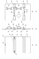
- FIG. 1 is a view for explaining the protective shield 10 of the first embodiment.
- FIG. 1A is a front view of the protective shield 10
- FIG. 1B is a side view of the protective shield 10
- FIG. 1C is a rear view of the protective shield 10.
- the front surface of the protective shield 10 is a surface that is attacked, and the back surface is a surface that is gripped by the user.
- the protective shield 10 is gripped by guards, police officers, and other personnel and used for suppression of demonstrations and guarding important persons, and protects the body from attacks.
- the protective shield 10 shown in FIG. 1 shows a use state in which a plurality of panels are opened so as to extend flush with each other, and when not used, can be folded to be small.
- the protective shield 10 includes a first panel 12, a second panel 14, a third panel 16, a first hinge 18, a spring member 19, a second hinge 20, a first handle 22, a second handle 24, and a first handle 24.
- a lock mechanism 26, a second lock mechanism 28, a first guard portion 30, a second guard portion 32, and a locking mechanism 34 are provided.
- the plurality of panels 12, 14, 16 are rotatably connected by hinges 18, 20, and assume a folded state and an open state.
- the first panel 12 is located at the top
- the second panel 14 is located at the center
- the third panel 16 is located at the bottom
- the panels 12, 14, 16 are arranged side by side in the vertical direction.
- FIG. 1B shows a state in which the protective shield 10 is opened and a plurality of panels 12, 14, 16 are arranged on the same plane.
- the third panel 16 may be in a slightly bent state. That is, the second panel 14 may be inclined with respect to the first panel 12 and / or the third panel 16 may be inclined with respect to the second panel 14 to constitute a use state.
- the first panel 12 and the second panel 14 are connected to the first hinge 18, and the second panel 14 and the third panel 16 are connected to the second hinge 20.
- the panels 12, 14, and 16 may be formed in a flat plate shape or a curved shape, and may be formed of a material such as stainless steel, titanium, duralumin, ceramic, a fiber bulletproof plate, or plastic.
- the first hinge portion 18 and the second hinge portion 20 are provided as a pair, respectively, and are provided on the surfaces of the panels 12, 14, 16 when the plurality of panels 12, 14, 16 are open. It is attached.
- the first hinge portion 18 is provided with a spring member 19 for urging the first panel 12 and the second panel 14 in the opening direction.
- the first hinge portion 18 and the second hinge portion 20 are provided over substantially the entire area of the protective shield 10 in the width direction.
- the first handle portion 22 is provided on the back surface of the first panel 12, and the second handle portion 24 and the third handle portion 25 are provided as a pair on the back surface of the second panel 14.
- the handle parts 22, 24, 25 are gripped by the user.
- the second handle portion 24 and the third handle portion 25 are arranged side by side, and the user can insert one arm into the third handle portion 25 and hold the second handle portion 24, and the second handle portion with both hands. It is also possible to hold the 24 and the third handle 25.
- the third handle portion 25 is configured by winding a belt, and is bendable.
- the handles 22, 24 have a rotatable shaft structure at the root portion, and can be rotated when not in use so that the height of the handles 22, 24 in the direction perpendicular to the panel surface can be changed along the panel. May be configured.
- the handle portions 22 and 24 may be configured by combining the halves, and the height in the direction perpendicular to the panel surface may be reduced by expanding both halves by rotating the shaft structure. Thereby, the protective shield 10 can be made thinner in a state where the plurality of panels 12, 14, 16 are folded.
- the first handle portion 22 may be constituted by a flexible belt.
- the first lock mechanism 26 is provided on the back surfaces of the first panel 12 and the second panel 14, and the second lock mechanism 28 is provided on the back surfaces of the second panel 14 and the third panel 16. Is provided.
- the first lock mechanism 26 regulates the rotation of the opened first panel 12 and the second panel 14, and the second lock mechanism 28 regulates the rotation of the opened second panel 14 and the third panel 16. I do.
- the first lock mechanism 26 will be described in detail with reference to a new drawing.
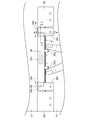
- FIG. 2 is a view for explaining the first lock mechanism 26.
- FIG. 2 is an enlarged view of the first lock mechanism 26.
- FIG. 3 is a sectional view taken along line AA of the first lock mechanism 26 shown in FIG.
- FIG. 4 is a sectional view taken along line BB of the first lock mechanism 26 shown in FIG. In FIG. 4, the first hinge portion 18 is omitted.
- the first lock mechanism 26 has a pair of lock pieces 26a, a case 26b, a pair of locking portions 26c, a pair of operation portions 26d, and an urging member 26e.
- the case 26b is formed in a tubular shape, and accommodates the pair of lock pieces 26a and the urging member 26e.
- the case 26b is formed in a tubular shape, and accommodates a pair of lock pieces 26a and a biasing member 26e.
- the case 26b is fixed to an end of the first panel 12, and extends in parallel with a boundary B between the first panel 12 and the second panel 14. Both ends of the case 26b are open so that the distal ends of the pair of lock pieces 26a can enter and exit.
- the pair of lock pieces 26a are provided on the case 26b so as to be able to advance and retreat, slide in the direction along the boundary B, and project from the both ends of the case 26b in opposite directions. Since the lock piece 26a is housed in the case 26b, it is provided on the second panel 14 side.
- the urging member 26e is located between the pair of lock pieces 26a and urges the pair of lock pieces 26a in the traveling direction.
- the biasing member 26e is arranged coaxially with the forward and backward directions of the pair of lock pieces 26a.
- the traveling direction of the lock piece 26a is a direction in which the tip of the lock piece 26a goes out of the case 26b, and the retreating direction of the lock piece 26a is a direction in which the tip side of the lock piece 26a is drawn into the case 26b.
- the operation part 26d is provided on each of the pair of lock pieces 26a.
- the operation portion 26d is inserted into a long hole formed in the case 26b, and protrudes outside from a slit formed in the middle of the case 26b.
- the operation part 26d may be screwed into a screw hole formed in the lock piece 26a.
- the operation part 26d also functions as a stopper that stops the advance of the lock piece 26a by hitting the edge of the long hole of the case 26b.
- the locking portion 26c is formed in a plate shape, fixed to the second panel 14, and locked to the lock piece 26a.
- the locking portion 26c extends from the second panel 14 beyond the boundary B toward the first panel 12.
- a stepped stopper 48 is formed at the tip of the locking portion 26c to prevent the locking between the locking portion 26c and the lock piece 26a from being released. The stopper 48 hits the lock piece 26a to limit the movement of the first panel 12 in the folding direction.
- the first lock mechanism 26 locks the rotation of the first panel 12 and the second panel 14 in a state where the locking portion 26c enters the gap between the lock piece 26a and the second panel 14. Take the state. In the locked state, the movement of the locking portion 26c separating from the second panel 14 is restricted by the lock piece 26a.
- the rotation of the first panel 12 and the second panel 14 can be regulated stably, and the first panel 12 and the second panel 14 Rattle can be suppressed.
- the second lock mechanism 28 has the same configuration as the lock piece 26a, the case 26b, the locking part 26c, the operation part 26d, and the urging member 26e of the first lock mechanism 26, and the user can release the lock with one hand. is there.
- the operation part 26 d of the first lock mechanism 26 is provided so as to protrude from the first panel 12 toward the second panel 14, and the operation part of the second lock mechanism 28 is By providing the second handle 14 so as to protrude toward the second panel 14, the lock release operation is facilitated while the user holds the second handle 24 or the third handle 25.
- a first tapered surface 40 and a second tapered surface 42 are formed at the tip of the lock piece 26a.
- the first tapered surface 40 is formed on the surface of the lock piece 26a and is inclined toward the tip of the lock piece 26a so as to approach the second panel 14.
- the lock piece 26a is slid in the retreating direction against the locking portion 26c.
- the first tapered surface 40 is more inclined than the second tapered surface 42 with respect to the second panel 14 of the lock piece 26a.
- the second tapered surface 42 is formed on the back surface of the lock piece 26a and is inclined away from the second panel 14 toward the tip of the lock piece 26a.
- the locking portion 26c has a first inclined surface 44 which is inclined so as to become thinner toward the first locking mechanism 26, and a second formed at a corner located on the side of the first locking mechanism 26 behind the locking portion 26c. And an inclined surface 46.
- the second tapered surface 42 contacts the first inclined surface 44 in the locked state.
- the inclination angles of the second tapered surface 42 and the first inclined surface 44 with respect to the second panel 14 may be different. By inclining the second tapered surface 42 and the first inclined surface 44, it is possible to prevent a gap from being formed in the second tapered surface 42 and the first inclined surface 44 in the locked state, and the first panel 12 and the second panel 14 are formed. Can be prevented from rattling.
- the second inclined surface 46 comes into contact with the first tapered surface 40 in the locked state, so that the first tapered surface 40 can be easily slid and the lock piece 26a can be easily retreated.
- the first guard portion 30 is fixed to the back surface of the second panel 14 and projects toward the adjacent first panel 12, and the second guard portion 32 is fixed to the back surface of the third panel 16 and is adjacent to the second panel 12. Overhang toward 14.
- the guard portions 30 and 32 are plate-shaped, are located on the back side of the second panel 14 and the third panel 16 in the open state, and cover a part of the boundary between the adjacent panels 12, 14 and 16 in the open state. .
- the guard portions 30 and 32 can increase the strength of the panel 12, 14 and 16 against the bending operation, and can sufficiently secure the protection performance when the boundary between the panels 12, 14 and 16 is impacted. it can.
- the locking mechanism 34 is composed of two male and female members provided on the front surface of the first panel 12 and the back surface of the third panel 16, and engages in an uneven manner. Take the locked state with.
- the locking mechanism 34 locks the plurality of panels 12, 14, 16 in a folded state, suppresses the panels 12, 14, 16 from opening, and facilitates the transport of the protective shield 10.
- FIG. 5 is a view for explaining the protective shield 10 in a state where the plurality of panels 12, 14, 16 are folded.
- the length in the vertical direction is small, and it is easy to secure a space for storage. Yes, it is easy to carry in a bag.
- the first guard portion 30 projects from the second panel 14 with the same length as the locking portion 26c. Thereby, the first guard portion 30 can protect the locking portion 26c.
- the second guard portion 32 also protects the locking portion of the second lock mechanism 28 in the same manner as the first guard portion 30.
- the first handle portion 22, the second handle portion 24, and the third handle portion 25 are provided on the panels 12, 14, 16 in a state where the plurality of panels 12, 14, 16 are folded. Located on the outer surface. Thereby, the protective shield 10 can be made thinner than the case where the handles 22, 24, 25 are arranged between the first panel 12 and the second panel 14 in the folded state, and the handles 22, 24, 25 are gripped. Can be carried around.
- the locking mechanism 34 is in a state of being fitted and locked, and the movement of the first panel 12 and the third panel 16 away from each other is restricted.
- the first hinge portion 18 is configured to be thicker than the second hinge portion 20 in order to secure a space for disposing the third panel 16.
- a flat spacer may be provided between the first hinge portion 18 and the first panel 12 and the second panel 14. It is fixed to the first panel 12 and the second panel 14 via a spacer 38. Thereby, a space for disposing the third panel 16 between the first panel 12 and the second panel 14 can be secured.
- the spacer 38 is not used for fixing the second hinge portion 20 unlike the first hinge portion 18. The spacing between the folded panels 12, 14, 16 can be adjusted by the spacer 38.
- FIG. 6 is a diagram for explaining the opening operation of the protective shield 10.
- the user grips the second handle portion 24 and the third handle portion 25 with one hand, and the locking mechanism 34 with the other hand. Release the lock.
- the first panel 12 rotates in the opening direction by the bias of the spring member 19, opens the first panel 12 as shown in FIG. It rotates under its own weight, and the third panel 16 opens as shown in FIG. In this way, the user can easily open the plurality of panels 12, 14, 16 from the folded state by gripping the second handle portion 24 and the third handle portion 25. By gripping and opening the second panel 14 located at the center, the first panel 12 can easily take a posture protecting the user's head.
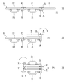
- FIG. 7 is a diagram for explaining the operation of the first lock mechanism 26.
- the first hinge 18 rotates the first panel 12 with respect to the second panel 14.
- the first hinge portion 18 includes a pair of fixed plates 18a fixed to the first panel 12 and the second panel 14, respectively, and a shaft portion 18b that supports the pair of fixed plates 18a.
- the first inclined surface 44 is formed on the surface of the locking portion 26c and is concave, and the lock piece 26a is locked in the concave portion.
- the tip of the locking portion 26c is not concave, and a stopper 48 protruding from the bottom of the first inclined surface 44 is formed. Since the lock piece 26a is hooked on the stopper 48, it is possible to prevent the lock piece 26a from slipping on the first inclined surface 44 due to an impact or the like and being unlocked. In addition, rattling of the first panel 12 and the second panel 14 in the open state by the stopper 48 can be suppressed.
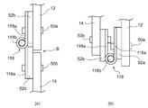
- FIG. 8 is a view for explaining a hinge portion 118 according to a modification.
- the first lock mechanism 26 is omitted.
- the hinge portion 118 of the modified example is different from the first hinge portion 18 shown in FIG. 7C in the position of the shaft portion 118b.
- the hinge 118 has a pair of fixed plates 118a fixed to the adjacent panels 12 and 14, respectively, and a shaft 118b that rotatably supports the pair of fixed plates 118a. Note that the pair of fixing plates 118a are fixed to the panels 12, 14 via the first spacer 52a or the second spacer 52b, respectively.
- the -axis portion 118b is provided at a position vertically displaced from the boundary B between the adjacent panels 12, 14 in the open state shown in FIG. 8A.
- the fixed plate 118a and the second spacer 52b cover the boundary B.
- the fixing plate 118a extends over the entire width of the protective shield 10. Accordingly, when the protective shield 10 is attacked by a sharp object or the like at the position of the boundary B, it can be prevented by the fixing plate 118a and the second spacer 52b.
- the second spacer 52b is positioned so as to overlap the first panel 12 beyond the boundary B from the second panel 14 and abuts on the first panel 12, so that the first panel 12 and the second panel 14 in the open state are provided. Rattling in the rotation direction can be suppressed.
- first fastener 50a and the second fastener 50b are fixed to the first panel 12 by the first fastener 50a, and the other fixing plate 118a and the second spacer 52b are fixed to the second panel 14 by the second fastener 50b. Is done.
- the first fastener 50a and the second fastener 50b are provided at positions displaced in the vertical direction of the panel. Thereby, interference between the first fastener 50a and the second fastener 50b can be suppressed.
- FIG. 8 shows a mode in which the fixing plate 118a is fixed to the first panel 12 and the second panel 14 via the first spacer 52a and the second spacer 52b.
- the present invention is not limited to this mode. May be directly fixed to the first panel 12 and the second panel 14. Even in this mode, the fixing plate 118a is provided so as to cover the boundary B, so that an attack on the position of the boundary B can be prevented. Further, since the fixing plate 118a is positioned so as to overlap the first panel 12 and the second panel 14, rattling of the first panel 12 and the second panel 14 in the rotation direction can be suppressed.
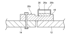
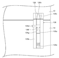
- FIG. 9 is a view for explaining a lock mechanism 126 according to a modification.
- the lock mechanism 126 of the modified example is a so-called latch lock, and is provided in a pair on the first panel 12 and the second panel 14.
- the lock mechanism 126 has a lock piece 126a, a case 126b, a locking portion 126c, an operation portion 126d, a biasing member 126e, a positioning portion 126f, and a slit 126g.
- the case 126b is fixed to the second panel 14, and accommodates the rod-shaped lock piece 126a so as to be able to advance and retreat.
- the lock piece 126a is urged by the urging member 126e in the traveling direction, that is, in the locking direction.
- the operation part 126d is provided so as to protrude radially from the middle of the lock piece 126a, and receives an operation for retracting the lock piece 126a to release the lock.
- the operation part 126d protrudes outside from a slit 126g formed in the case 126b.
- a positioning portion 126f is formed at the center of the slit 126g of the case 126b. The positioning portion 126f extends in the circumferential direction so as to narrow the center of the slit 126g.
- the locking portion 126c is fixed to the first panel 12, and has a hole 126i capable of receiving the tip portion 126h of the lock piece 126a.
- the hole 126i is formed in a smooth conical shape.
- the tip 126h of the lock piece 126a is formed in a conical shape.
- the hole 126i and the tip 126h may be formed at substantially the same inclination angle.
- the tip portion 126h is a portion protruding from the case 126b, and the portion protruding from the case 126b is formed in a conical shape, or the portion insertable into the hole 126i is formed in a conical shape.
- FIG. 9 shows the lock mechanism 126 in the locked state. However, when the user grips the operation unit 126d and retreats the lock piece 126a, the lock mechanism 126 is in the unlocked state, and the first panel 12 and the second panel The panel 14 can be folded.
- the second spacer 52b is brought into contact with the first panel 12 by displacing the shaft portion 118b from the boundary B, so that the first panel 12 and the second panel 14 in the open state are formed. It is possible to stably insert the distal end portion 126h into the hole portion 126i while suppressing rattling.
- the mode in which the panels 12, 14, 16 are vertically connected has been described. Also. In the embodiment, the embodiment in which the protective shield 10 is configured by the three panels 12, 14, and 16 has been described. However, the embodiment is not limited thereto, and may be configured by two or four panels.
- each of the lock pieces 26a may be housed in a case.
- at least one pair of lock pieces 26a is provided on the left and right.
- the locking portion 26c is provided so as to extend from the second panel 14 to the first panel 12, and the lock piece 26a is provided in a direction orthogonal to the direction in which the locking portion 26c extends.
- the present invention is not limited to this mode.
- a mode may be employed in which a lock piece that can move forward and backward is provided so as to project from the second panel 14 to the first panel 12, and the locking portion is fixed to the first panel 12.
- the arrangement of the lock pieces 26a and the locking portions 26c may be reversed.
- the mode in which the first handle portion 22 is provided on the first panel 12 has been described.
- the present invention is not limited to this mode, and the first panel 12 may not have the first handle portion 22.
- the first panel 12 may be provided with a window for securing the field of view of the user.
- the window is provided by cutting out the first panel 12, and a transparent member is fixed to the position where the window is formed from the front side.
- first hinge portion 18 is provided with the spring member 19 and the second hinge portion 20 is not provided with the spring member.
- a spring member for urging the second panel 14 and the third panel 16 in the opening direction may be provided on the second hinge portion 20.
- the present invention is not limited to this mode.
- the spring member 19 may be provided on the first hinge portion 18 integrally formed over the entire region in the width direction.
- the present invention relates to a protective shield capable of folding a plurality of panels.
Landscapes
- Engineering & Computer Science (AREA)
- General Engineering & Computer Science (AREA)
- Aiming, Guidance, Guns With A Light Source, Armor, Camouflage, And Targets (AREA)
- Handcart (AREA)
Abstract
La présente invention concerne un écran de protection qui comprend : une pluralité de panneaux reliés de façon à être dans un état plié ou dans un état ouvert ; une partie à poignée prévue sur au moins un panneau ; des parties à articulation qui relient de manière rotative la pluralité de panneaux ; et un mécanisme de verrouillage qui limite la rotation de panneaux adjacents dans un état où la pluralité de panneaux sont ouverts. Le mécanisme de verrouillage comprend : une pièce de verrouillage prévue sur un panneau de la pluralité de panneaux, de façon à pouvoir avancer et se rétracter ; un élément de poussée qui pousse la pièce de verrouillage dans la direction d'avance ; et une partie de verrouillage qui est prévue sur un autre panneau de la pluralité de panneaux et qui peut être verrouillée sur la pièce de verrouillage.
Priority Applications (2)
| Application Number | Priority Date | Filing Date | Title |
|---|---|---|---|
| PCT/JP2018/024534 WO2020003431A1 (fr) | 2018-06-28 | 2018-06-28 | Écran de protection |
| JP2020526800A JP6993635B2 (ja) | 2018-06-28 | 2018-06-28 | 防護盾 |
Applications Claiming Priority (1)
| Application Number | Priority Date | Filing Date | Title |
|---|---|---|---|
| PCT/JP2018/024534 WO2020003431A1 (fr) | 2018-06-28 | 2018-06-28 | Écran de protection |
Publications (1)
| Publication Number | Publication Date |
|---|---|
| WO2020003431A1 true WO2020003431A1 (fr) | 2020-01-02 |
Family
ID=68984714
Family Applications (1)
| Application Number | Title | Priority Date | Filing Date |
|---|---|---|---|
| PCT/JP2018/024534 Ceased WO2020003431A1 (fr) | 2018-06-28 | 2018-06-28 | Écran de protection |
Country Status (2)
| Country | Link |
|---|---|
| JP (1) | JP6993635B2 (fr) |
| WO (1) | WO2020003431A1 (fr) |
Citations (6)
| Publication number | Priority date | Publication date | Assignee | Title |
|---|---|---|---|---|
| JPS6386589U (fr) * | 1986-11-21 | 1988-06-06 | ||
| JP2003013647A (ja) * | 2001-07-03 | 2003-01-15 | Piolax Inc | 収納体のサイドロック装置 |
| US6807890B1 (en) * | 2002-05-13 | 2004-10-26 | Patriot3, Inc. | Collapsible ballistic shield |
| CN205593431U (zh) * | 2016-04-26 | 2016-09-21 | 成都爱可信科技有限公司 | 一种带执法记录仪的盾牌 |
| JP3214456U (ja) * | 2017-10-30 | 2018-01-18 | 有限会社小澤空調機器製作所 | 換気口装置 |
| US20180120063A1 (en) * | 2015-04-17 | 2018-05-03 | Saintpro Ab | Foldable shield |
-
2018
- 2018-06-28 WO PCT/JP2018/024534 patent/WO2020003431A1/fr not_active Ceased
- 2018-06-28 JP JP2020526800A patent/JP6993635B2/ja active Active
Patent Citations (6)
| Publication number | Priority date | Publication date | Assignee | Title |
|---|---|---|---|---|
| JPS6386589U (fr) * | 1986-11-21 | 1988-06-06 | ||
| JP2003013647A (ja) * | 2001-07-03 | 2003-01-15 | Piolax Inc | 収納体のサイドロック装置 |
| US6807890B1 (en) * | 2002-05-13 | 2004-10-26 | Patriot3, Inc. | Collapsible ballistic shield |
| US20180120063A1 (en) * | 2015-04-17 | 2018-05-03 | Saintpro Ab | Foldable shield |
| CN205593431U (zh) * | 2016-04-26 | 2016-09-21 | 成都爱可信科技有限公司 | 一种带执法记录仪的盾牌 |
| JP3214456U (ja) * | 2017-10-30 | 2018-01-18 | 有限会社小澤空調機器製作所 | 換気口装置 |
Also Published As
| Publication number | Publication date |
|---|---|
| JPWO2020003431A1 (ja) | 2021-08-12 |
| JP6993635B2 (ja) | 2022-01-13 |
Similar Documents
| Publication | Publication Date | Title |
|---|---|---|
| EP3998892A1 (fr) | Casque de protection pourvu d'un écran de protection faciale et d'un mécanisme d'articulation | |
| TWI602738B (zh) | 電動自行車及其電池承載裝置 | |
| US7574804B2 (en) | Knife with sliding blade and disengageable deployment mechanism | |
| US10375944B2 (en) | Convertible fishing rod carrier | |
| US5398447A (en) | Centrally located tilt-in window handle | |
| US6257029B1 (en) | Computer lock having double locking leaves | |
| US9839272B2 (en) | Composite luggage protection assembly | |
| CN103261831B (zh) | 手枪套 | |
| US12539627B2 (en) | Locking foldable knife with double locking mechanism | |
| US20190230911A1 (en) | Convertible fishing rod carrier | |
| JP2022511887A (ja) | バタフライナイフ用ラッチレスロック機構 | |
| US6874827B1 (en) | Temporary latches | |
| WO2020003431A1 (fr) | Écran de protection | |
| US5471778A (en) | Collapsible net assembly capable of rotatably closing the support rods upon which the net is supported | |
| CN103874437A (zh) | 警棍套以及在警棍套中的配置 | |
| US20120174413A1 (en) | Folding utility knives with retractable blade | |
| US9004051B2 (en) | Folding take-down flat archery bow | |
| JP6608551B2 (ja) | 防護盾 | |
| ES2686997T3 (es) | Cuadro con puertas secundarias giratorias y método para la gestión de transductores | |
| JPH0998824A (ja) | トランクまたはこれに類する容器 | |
| TR201606429A2 (tr) | Entegre bagaj kapaği | |
| CN212912292U (zh) | 一种联锁式资料柜 | |
| CN101564844B (zh) | 禁止刀柄意外开启的手动刀 | |
| US20190313757A1 (en) | Handle and method of deploying a handle | |
| CN111636780A (zh) | 支撑装置、发动机舱和工程机械 |
Legal Events
| Date | Code | Title | Description |
|---|---|---|---|
| 121 | Ep: the epo has been informed by wipo that ep was designated in this application |
Ref document number: 18924945 Country of ref document: EP Kind code of ref document: A1 |
|
| ENP | Entry into the national phase |
Ref document number: 2020526800 Country of ref document: JP Kind code of ref document: A |
|
| NENP | Non-entry into the national phase |
Ref country code: DE |
|
| 122 | Ep: pct application non-entry in european phase |
Ref document number: 18924945 Country of ref document: EP Kind code of ref document: A1 |