WO2020003431A1 - 防護盾 - Google Patents
防護盾 Download PDFInfo
- Publication number
- WO2020003431A1 WO2020003431A1 PCT/JP2018/024534 JP2018024534W WO2020003431A1 WO 2020003431 A1 WO2020003431 A1 WO 2020003431A1 JP 2018024534 W JP2018024534 W JP 2018024534W WO 2020003431 A1 WO2020003431 A1 WO 2020003431A1
- Authority
- WO
- WIPO (PCT)
- Prior art keywords
- panels
- panel
- pair
- lock
- protective shield
- Prior art date
- Legal status (The legal status is an assumption and is not a legal conclusion. Google has not performed a legal analysis and makes no representation as to the accuracy of the status listed.)
- Ceased
Links
Images



Classifications
-
- F—MECHANICAL ENGINEERING; LIGHTING; HEATING; WEAPONS; BLASTING
- F41—WEAPONS
- F41H—ARMOUR; ARMOURED TURRETS; ARMOURED OR ARMED VEHICLES; MEANS OF ATTACK OR DEFENCE, e.g. CAMOUFLAGE, IN GENERAL
- F41H5/00—Armour; Armour plates
- F41H5/06—Shields
- F41H5/08—Shields for personal use, i.e. hand held shields
Definitions
- the present invention relates to a protective shield capable of folding a plurality of panels.
- Patent Literature 1 discloses a foldable protective shield having two shield plates, a support arm that connects the two shield plates so as to be rotatable left and right, and a rotating shaft.
- the rotating shaft disclosed in Patent Document 1 has a lock shaft for stopping rotation of the rotating shaft, a pickup ring for lifting and unlocking the lock shaft, and a spring for pulling back the lock shaft in a locking direction. .
- the user can open or fold the two shields of the foldable protective shield while keeping the pickup ring raised.
- Patent Document 1 Although the folding type protective shield disclosed in Patent Document 1 can be folded to reduce the left-right width, the rotating shaft that is also used for the handle in the folded state is disposed inside, and it is not easy for the user to carry.
- the present invention has been made in view of such a problem, and an object of the present invention is to provide a protective shield in which a plurality of panels are folded down to be small and easy to transport and store.
- a protective shield includes a plurality of panels connected to be in a folded state or an open state, a handle provided on at least one panel, and a plurality of panels. And a lock mechanism for restricting the rotation of adjacent panels when the plurality of panels are open.
- the handle is located on an outer surface of the panel with the plurality of panels folded.
- the lock mechanism is provided on one of the plurality of panels and is provided with a lock piece provided to be able to advance and retreat, a biasing member for biasing the lock piece in the traveling direction, and provided on the other panel of the plurality of panels. And a locking portion that can be locked to the lock piece.
- the protective shield includes a plurality of panels connected in a folded state or an open state, a handle provided on at least one panel, a hinge part rotatably connecting the plurality of panels, And a lock mechanism for restricting the rotation of adjacent panels when the panel is opened.
- the handle is located on an outer surface of the panel with the plurality of panels folded.
- the hinge portion includes a pair of fixed plates fixed to adjacent panels, and a shaft portion rotatably supporting the pair of fixed plates. The shaft portion is provided at a position shifted from a boundary between adjacent panels.
- a protective shield in which a plurality of panels are folded and reduced in size to facilitate transport and storage.
- FIG. 3 is a sectional view taken along line AA of the first lock mechanism shown in FIG. 2.
- FIG. 3 is a sectional view taken along line BB of the first lock mechanism shown in FIG. 2.
- FIG. 9 is a diagram for explaining the operation of the first lock mechanism. It is a figure for explaining a hinge part of a modification.
- FIG. 11 is a diagram for describing a lock mechanism according to a modification.
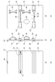
- FIG. 1 is a view for explaining the protective shield 10 of the first embodiment.
- FIG. 1A is a front view of the protective shield 10
- FIG. 1B is a side view of the protective shield 10
- FIG. 1C is a rear view of the protective shield 10.
- the front surface of the protective shield 10 is a surface that is attacked, and the back surface is a surface that is gripped by the user.
- the protective shield 10 is gripped by guards, police officers, and other personnel and used for suppression of demonstrations and guarding important persons, and protects the body from attacks.
- the protective shield 10 shown in FIG. 1 shows a use state in which a plurality of panels are opened so as to extend flush with each other, and when not used, can be folded to be small.
- the protective shield 10 includes a first panel 12, a second panel 14, a third panel 16, a first hinge 18, a spring member 19, a second hinge 20, a first handle 22, a second handle 24, and a first handle 24.
- a lock mechanism 26, a second lock mechanism 28, a first guard portion 30, a second guard portion 32, and a locking mechanism 34 are provided.
- the plurality of panels 12, 14, 16 are rotatably connected by hinges 18, 20, and assume a folded state and an open state.
- the first panel 12 is located at the top
- the second panel 14 is located at the center
- the third panel 16 is located at the bottom
- the panels 12, 14, 16 are arranged side by side in the vertical direction.
- FIG. 1B shows a state in which the protective shield 10 is opened and a plurality of panels 12, 14, 16 are arranged on the same plane.
- the third panel 16 may be in a slightly bent state. That is, the second panel 14 may be inclined with respect to the first panel 12 and / or the third panel 16 may be inclined with respect to the second panel 14 to constitute a use state.
- the first panel 12 and the second panel 14 are connected to the first hinge 18, and the second panel 14 and the third panel 16 are connected to the second hinge 20.
- the panels 12, 14, and 16 may be formed in a flat plate shape or a curved shape, and may be formed of a material such as stainless steel, titanium, duralumin, ceramic, a fiber bulletproof plate, or plastic.
- the first hinge portion 18 and the second hinge portion 20 are provided as a pair, respectively, and are provided on the surfaces of the panels 12, 14, 16 when the plurality of panels 12, 14, 16 are open. It is attached.
- the first hinge portion 18 is provided with a spring member 19 for urging the first panel 12 and the second panel 14 in the opening direction.
- the first hinge portion 18 and the second hinge portion 20 are provided over substantially the entire area of the protective shield 10 in the width direction.
- the first handle portion 22 is provided on the back surface of the first panel 12, and the second handle portion 24 and the third handle portion 25 are provided as a pair on the back surface of the second panel 14.
- the handle parts 22, 24, 25 are gripped by the user.
- the second handle portion 24 and the third handle portion 25 are arranged side by side, and the user can insert one arm into the third handle portion 25 and hold the second handle portion 24, and the second handle portion with both hands. It is also possible to hold the 24 and the third handle 25.
- the third handle portion 25 is configured by winding a belt, and is bendable.
- the handles 22, 24 have a rotatable shaft structure at the root portion, and can be rotated when not in use so that the height of the handles 22, 24 in the direction perpendicular to the panel surface can be changed along the panel. May be configured.
- the handle portions 22 and 24 may be configured by combining the halves, and the height in the direction perpendicular to the panel surface may be reduced by expanding both halves by rotating the shaft structure. Thereby, the protective shield 10 can be made thinner in a state where the plurality of panels 12, 14, 16 are folded.
- the first handle portion 22 may be constituted by a flexible belt.
- the first lock mechanism 26 is provided on the back surfaces of the first panel 12 and the second panel 14, and the second lock mechanism 28 is provided on the back surfaces of the second panel 14 and the third panel 16. Is provided.
- the first lock mechanism 26 regulates the rotation of the opened first panel 12 and the second panel 14, and the second lock mechanism 28 regulates the rotation of the opened second panel 14 and the third panel 16. I do.
- the first lock mechanism 26 will be described in detail with reference to a new drawing.
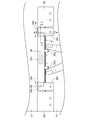
- FIG. 2 is a view for explaining the first lock mechanism 26.
- FIG. 2 is an enlarged view of the first lock mechanism 26.
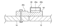
- FIG. 3 is a sectional view taken along line AA of the first lock mechanism 26 shown in FIG.
- FIG. 4 is a sectional view taken along line BB of the first lock mechanism 26 shown in FIG. In FIG. 4, the first hinge portion 18 is omitted.
- the first lock mechanism 26 has a pair of lock pieces 26a, a case 26b, a pair of locking portions 26c, a pair of operation portions 26d, and an urging member 26e.
- the case 26b is formed in a tubular shape, and accommodates the pair of lock pieces 26a and the urging member 26e.
- the case 26b is formed in a tubular shape, and accommodates a pair of lock pieces 26a and a biasing member 26e.
- the case 26b is fixed to an end of the first panel 12, and extends in parallel with a boundary B between the first panel 12 and the second panel 14. Both ends of the case 26b are open so that the distal ends of the pair of lock pieces 26a can enter and exit.
- the pair of lock pieces 26a are provided on the case 26b so as to be able to advance and retreat, slide in the direction along the boundary B, and project from the both ends of the case 26b in opposite directions. Since the lock piece 26a is housed in the case 26b, it is provided on the second panel 14 side.
- the urging member 26e is located between the pair of lock pieces 26a and urges the pair of lock pieces 26a in the traveling direction.
- the biasing member 26e is arranged coaxially with the forward and backward directions of the pair of lock pieces 26a.
- the traveling direction of the lock piece 26a is a direction in which the tip of the lock piece 26a goes out of the case 26b, and the retreating direction of the lock piece 26a is a direction in which the tip side of the lock piece 26a is drawn into the case 26b.
- the operation part 26d is provided on each of the pair of lock pieces 26a.
- the operation portion 26d is inserted into a long hole formed in the case 26b, and protrudes outside from a slit formed in the middle of the case 26b.
- the operation part 26d may be screwed into a screw hole formed in the lock piece 26a.
- the operation part 26d also functions as a stopper that stops the advance of the lock piece 26a by hitting the edge of the long hole of the case 26b.
- the locking portion 26c is formed in a plate shape, fixed to the second panel 14, and locked to the lock piece 26a.
- the locking portion 26c extends from the second panel 14 beyond the boundary B toward the first panel 12.
- a stepped stopper 48 is formed at the tip of the locking portion 26c to prevent the locking between the locking portion 26c and the lock piece 26a from being released. The stopper 48 hits the lock piece 26a to limit the movement of the first panel 12 in the folding direction.
- the first lock mechanism 26 locks the rotation of the first panel 12 and the second panel 14 in a state where the locking portion 26c enters the gap between the lock piece 26a and the second panel 14. Take the state. In the locked state, the movement of the locking portion 26c separating from the second panel 14 is restricted by the lock piece 26a.
- the rotation of the first panel 12 and the second panel 14 can be regulated stably, and the first panel 12 and the second panel 14 Rattle can be suppressed.
- the second lock mechanism 28 has the same configuration as the lock piece 26a, the case 26b, the locking part 26c, the operation part 26d, and the urging member 26e of the first lock mechanism 26, and the user can release the lock with one hand. is there.
- the operation part 26 d of the first lock mechanism 26 is provided so as to protrude from the first panel 12 toward the second panel 14, and the operation part of the second lock mechanism 28 is By providing the second handle 14 so as to protrude toward the second panel 14, the lock release operation is facilitated while the user holds the second handle 24 or the third handle 25.
- a first tapered surface 40 and a second tapered surface 42 are formed at the tip of the lock piece 26a.
- the first tapered surface 40 is formed on the surface of the lock piece 26a and is inclined toward the tip of the lock piece 26a so as to approach the second panel 14.
- the lock piece 26a is slid in the retreating direction against the locking portion 26c.
- the first tapered surface 40 is more inclined than the second tapered surface 42 with respect to the second panel 14 of the lock piece 26a.
- the second tapered surface 42 is formed on the back surface of the lock piece 26a and is inclined away from the second panel 14 toward the tip of the lock piece 26a.
- the locking portion 26c has a first inclined surface 44 which is inclined so as to become thinner toward the first locking mechanism 26, and a second formed at a corner located on the side of the first locking mechanism 26 behind the locking portion 26c. And an inclined surface 46.
- the second tapered surface 42 contacts the first inclined surface 44 in the locked state.
- the inclination angles of the second tapered surface 42 and the first inclined surface 44 with respect to the second panel 14 may be different. By inclining the second tapered surface 42 and the first inclined surface 44, it is possible to prevent a gap from being formed in the second tapered surface 42 and the first inclined surface 44 in the locked state, and the first panel 12 and the second panel 14 are formed. Can be prevented from rattling.
- the second inclined surface 46 comes into contact with the first tapered surface 40 in the locked state, so that the first tapered surface 40 can be easily slid and the lock piece 26a can be easily retreated.
- the first guard portion 30 is fixed to the back surface of the second panel 14 and projects toward the adjacent first panel 12, and the second guard portion 32 is fixed to the back surface of the third panel 16 and is adjacent to the second panel 12. Overhang toward 14.
- the guard portions 30 and 32 are plate-shaped, are located on the back side of the second panel 14 and the third panel 16 in the open state, and cover a part of the boundary between the adjacent panels 12, 14 and 16 in the open state. .
- the guard portions 30 and 32 can increase the strength of the panel 12, 14 and 16 against the bending operation, and can sufficiently secure the protection performance when the boundary between the panels 12, 14 and 16 is impacted. it can.
- the locking mechanism 34 is composed of two male and female members provided on the front surface of the first panel 12 and the back surface of the third panel 16, and engages in an uneven manner. Take the locked state with.
- the locking mechanism 34 locks the plurality of panels 12, 14, 16 in a folded state, suppresses the panels 12, 14, 16 from opening, and facilitates the transport of the protective shield 10.
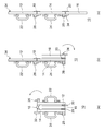
- FIG. 5 is a view for explaining the protective shield 10 in a state where the plurality of panels 12, 14, 16 are folded.
- the length in the vertical direction is small, and it is easy to secure a space for storage. Yes, it is easy to carry in a bag.
- the first guard portion 30 projects from the second panel 14 with the same length as the locking portion 26c. Thereby, the first guard portion 30 can protect the locking portion 26c.
- the second guard portion 32 also protects the locking portion of the second lock mechanism 28 in the same manner as the first guard portion 30.
- the first handle portion 22, the second handle portion 24, and the third handle portion 25 are provided on the panels 12, 14, 16 in a state where the plurality of panels 12, 14, 16 are folded. Located on the outer surface. Thereby, the protective shield 10 can be made thinner than the case where the handles 22, 24, 25 are arranged between the first panel 12 and the second panel 14 in the folded state, and the handles 22, 24, 25 are gripped. Can be carried around.
- the locking mechanism 34 is in a state of being fitted and locked, and the movement of the first panel 12 and the third panel 16 away from each other is restricted.
- the first hinge portion 18 is configured to be thicker than the second hinge portion 20 in order to secure a space for disposing the third panel 16.
- a flat spacer may be provided between the first hinge portion 18 and the first panel 12 and the second panel 14. It is fixed to the first panel 12 and the second panel 14 via a spacer 38. Thereby, a space for disposing the third panel 16 between the first panel 12 and the second panel 14 can be secured.
- the spacer 38 is not used for fixing the second hinge portion 20 unlike the first hinge portion 18. The spacing between the folded panels 12, 14, 16 can be adjusted by the spacer 38.
- FIG. 6 is a diagram for explaining the opening operation of the protective shield 10.
- the user grips the second handle portion 24 and the third handle portion 25 with one hand, and the locking mechanism 34 with the other hand. Release the lock.
- the first panel 12 rotates in the opening direction by the bias of the spring member 19, opens the first panel 12 as shown in FIG. It rotates under its own weight, and the third panel 16 opens as shown in FIG. In this way, the user can easily open the plurality of panels 12, 14, 16 from the folded state by gripping the second handle portion 24 and the third handle portion 25. By gripping and opening the second panel 14 located at the center, the first panel 12 can easily take a posture protecting the user's head.
- FIG. 7 is a diagram for explaining the operation of the first lock mechanism 26.
- the first hinge 18 rotates the first panel 12 with respect to the second panel 14.
- the first hinge portion 18 includes a pair of fixed plates 18a fixed to the first panel 12 and the second panel 14, respectively, and a shaft portion 18b that supports the pair of fixed plates 18a.
- the first inclined surface 44 is formed on the surface of the locking portion 26c and is concave, and the lock piece 26a is locked in the concave portion.
- the tip of the locking portion 26c is not concave, and a stopper 48 protruding from the bottom of the first inclined surface 44 is formed. Since the lock piece 26a is hooked on the stopper 48, it is possible to prevent the lock piece 26a from slipping on the first inclined surface 44 due to an impact or the like and being unlocked. In addition, rattling of the first panel 12 and the second panel 14 in the open state by the stopper 48 can be suppressed.
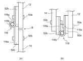
- FIG. 8 is a view for explaining a hinge portion 118 according to a modification.
- the first lock mechanism 26 is omitted.
- the hinge portion 118 of the modified example is different from the first hinge portion 18 shown in FIG. 7C in the position of the shaft portion 118b.
- the hinge 118 has a pair of fixed plates 118a fixed to the adjacent panels 12 and 14, respectively, and a shaft 118b that rotatably supports the pair of fixed plates 118a. Note that the pair of fixing plates 118a are fixed to the panels 12, 14 via the first spacer 52a or the second spacer 52b, respectively.
- the -axis portion 118b is provided at a position vertically displaced from the boundary B between the adjacent panels 12, 14 in the open state shown in FIG. 8A.
- the fixed plate 118a and the second spacer 52b cover the boundary B.
- the fixing plate 118a extends over the entire width of the protective shield 10. Accordingly, when the protective shield 10 is attacked by a sharp object or the like at the position of the boundary B, it can be prevented by the fixing plate 118a and the second spacer 52b.
- the second spacer 52b is positioned so as to overlap the first panel 12 beyond the boundary B from the second panel 14 and abuts on the first panel 12, so that the first panel 12 and the second panel 14 in the open state are provided. Rattling in the rotation direction can be suppressed.
- first fastener 50a and the second fastener 50b are fixed to the first panel 12 by the first fastener 50a, and the other fixing plate 118a and the second spacer 52b are fixed to the second panel 14 by the second fastener 50b. Is done.
- the first fastener 50a and the second fastener 50b are provided at positions displaced in the vertical direction of the panel. Thereby, interference between the first fastener 50a and the second fastener 50b can be suppressed.
- FIG. 8 shows a mode in which the fixing plate 118a is fixed to the first panel 12 and the second panel 14 via the first spacer 52a and the second spacer 52b.
- the present invention is not limited to this mode. May be directly fixed to the first panel 12 and the second panel 14. Even in this mode, the fixing plate 118a is provided so as to cover the boundary B, so that an attack on the position of the boundary B can be prevented. Further, since the fixing plate 118a is positioned so as to overlap the first panel 12 and the second panel 14, rattling of the first panel 12 and the second panel 14 in the rotation direction can be suppressed.
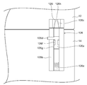
- FIG. 9 is a view for explaining a lock mechanism 126 according to a modification.
- the lock mechanism 126 of the modified example is a so-called latch lock, and is provided in a pair on the first panel 12 and the second panel 14.
- the lock mechanism 126 has a lock piece 126a, a case 126b, a locking portion 126c, an operation portion 126d, a biasing member 126e, a positioning portion 126f, and a slit 126g.
- the case 126b is fixed to the second panel 14, and accommodates the rod-shaped lock piece 126a so as to be able to advance and retreat.
- the lock piece 126a is urged by the urging member 126e in the traveling direction, that is, in the locking direction.
- the operation part 126d is provided so as to protrude radially from the middle of the lock piece 126a, and receives an operation for retracting the lock piece 126a to release the lock.
- the operation part 126d protrudes outside from a slit 126g formed in the case 126b.
- a positioning portion 126f is formed at the center of the slit 126g of the case 126b. The positioning portion 126f extends in the circumferential direction so as to narrow the center of the slit 126g.
- the locking portion 126c is fixed to the first panel 12, and has a hole 126i capable of receiving the tip portion 126h of the lock piece 126a.
- the hole 126i is formed in a smooth conical shape.
- the tip 126h of the lock piece 126a is formed in a conical shape.
- the hole 126i and the tip 126h may be formed at substantially the same inclination angle.
- the tip portion 126h is a portion protruding from the case 126b, and the portion protruding from the case 126b is formed in a conical shape, or the portion insertable into the hole 126i is formed in a conical shape.
- FIG. 9 shows the lock mechanism 126 in the locked state. However, when the user grips the operation unit 126d and retreats the lock piece 126a, the lock mechanism 126 is in the unlocked state, and the first panel 12 and the second panel The panel 14 can be folded.
- the second spacer 52b is brought into contact with the first panel 12 by displacing the shaft portion 118b from the boundary B, so that the first panel 12 and the second panel 14 in the open state are formed. It is possible to stably insert the distal end portion 126h into the hole portion 126i while suppressing rattling.
- the mode in which the panels 12, 14, 16 are vertically connected has been described. Also. In the embodiment, the embodiment in which the protective shield 10 is configured by the three panels 12, 14, and 16 has been described. However, the embodiment is not limited thereto, and may be configured by two or four panels.
- each of the lock pieces 26a may be housed in a case.
- at least one pair of lock pieces 26a is provided on the left and right.
- the locking portion 26c is provided so as to extend from the second panel 14 to the first panel 12, and the lock piece 26a is provided in a direction orthogonal to the direction in which the locking portion 26c extends.
- the present invention is not limited to this mode.
- a mode may be employed in which a lock piece that can move forward and backward is provided so as to project from the second panel 14 to the first panel 12, and the locking portion is fixed to the first panel 12.
- the arrangement of the lock pieces 26a and the locking portions 26c may be reversed.
- the mode in which the first handle portion 22 is provided on the first panel 12 has been described.
- the present invention is not limited to this mode, and the first panel 12 may not have the first handle portion 22.
- the first panel 12 may be provided with a window for securing the field of view of the user.
- the window is provided by cutting out the first panel 12, and a transparent member is fixed to the position where the window is formed from the front side.
- first hinge portion 18 is provided with the spring member 19 and the second hinge portion 20 is not provided with the spring member.
- a spring member for urging the second panel 14 and the third panel 16 in the opening direction may be provided on the second hinge portion 20.
- the present invention is not limited to this mode.
- the spring member 19 may be provided on the first hinge portion 18 integrally formed over the entire region in the width direction.
- the present invention relates to a protective shield capable of folding a plurality of panels.
Landscapes
- Engineering & Computer Science (AREA)
- General Engineering & Computer Science (AREA)
- Aiming, Guidance, Guns With A Light Source, Armor, Camouflage, And Targets (AREA)
- Handcart (AREA)
Abstract
防護盾10は、折り重ねた状態または開いた状態をとるように連結された複数のパネルと、少なくとも1つのパネルに設けられる把手部と、複数のパネルを回転可能に連結するヒンジ部と、複数のパネルが開いた状態で隣り合うパネルの回転を規制するロック機構と、を備える。ロック機構は、複数のパネルのうち一方のパネルに設けられ、進退可能に設けられるロック片と、ロック片を進行方向に付勢する付勢部材と、複数のパネルのうち他方のパネルに設けられ、ロック片に係止可能な係止部と、を有する。
Description
本発明は、複数のパネルを折り重ねることが可能な防護盾に関する。
人の身体を防護するための防護盾は、身体に合わせた大きさ、例えば縦幅1メートル程度に設定されるため、搬送や収納時に場所を取り容易でない。特許文献1には、2枚の盾板と、2枚の盾板を左右に回転可能に連結する支持アームおよび回転シャフトとを有する折りたたみ式防護盾が開示される。
また、特許文献1に開示される回転シャフトは、回転シャフトの回転を止めるためのロックシャフトと、ロックシャフトを引き上げてロック解除するピックアップリングと、ロックシャフトをロックする方向に引き戻すスプリングと、を有する。ユーザはピックアップリングを引き上げた状態を維持しつつ、折りたたみ式防護盾の2枚の盾板を開く、または折りたたむことができる。
特許文献1に開示される折りたたみ式防護盾は、折りたたむことで左右幅を短くできるものの、折りたたみ状態で把手にも用いられる回転シャフトが内側に配置されており、ユーザが持ち運ぶことが容易でない。
本発明はこのような課題に鑑みてなされたものであり、その目的は、複数のパネルを折り重ねて小型にして搬送および収納を容易にした防護盾を提供することにある。
上記課題を解決するために、本発明のある態様の防護盾は、折り重ねた状態または開いた状態をとるように連結された複数のパネルと、少なくとも1つのパネルに設けられる把手部と、複数のパネルを回転可能に連結するヒンジ部と、複数のパネルが開いた状態で隣り合うパネルの回転を規制するロック機構と、を備える。把手部は、複数のパネルを折り重ねた状態でパネルの外面に位置する。ロック機構は、複数のパネルのうち一方のパネルに設けられ、進退可能に設けられるロック片と、ロック片を進行方向に付勢する付勢部材と、複数のパネルのうち他方のパネルに設けられ、ロック片に係止可能な係止部と、を有する。
本発明の別の態様もまた、防護盾である。この防護盾は、折り重ねた状態または開いた状態をとるように連結された複数のパネルと、少なくとも1つのパネルに設けられる把手部と、複数のパネルを回転可能に連結するヒンジ部と、複数のパネルが開いた状態で隣り合うパネルの回転を規制するロック機構と、を備える。把手部は、複数のパネルを折り重ねた状態でパネルの外面に位置する。ヒンジ部は、隣り合うパネルにそれぞれ固定される一対の固定板と、一対の固定板を回転可能に軸支する軸部と、を有する。軸部は、隣り合うパネルの境界からずれた位置に設けられる。
本発明によれば、複数のパネルを折り重ねて小型にして搬送および収納を容易にした防護盾を提供できる。
図1は、第1実施例の防護盾10について説明するための図である。図1(a)は防護盾10の表面図であり、図1(b)は防護盾10の側面図であり、図1(c)は防護盾10の裏面図である。防護盾10の表面は、攻撃を受ける面であり、裏面はユーザが把持する側の面である。
防護盾10は、警備員や警察官等の人員により把持されて、デモなどの鎮圧や要人の警護等に用いられ、攻撃から身体を防護する。図1に示す防護盾10は、複数のパネルを面一に延在するように開いた使用状態を示しており、使用しない場合には折り重ねて小型にできる。
防護盾10は、第1パネル12、第2パネル14、第3パネル16、第1ヒンジ部18、バネ部材19、第2ヒンジ部20、第1把手部22、第2把手部24、第1ロック機構26、第2ロック機構28、第1ガード部30、第2ガード部32、係止機構34を備える。
複数のパネル12,14,16は、ヒンジ部18,20により回転可能に連結しており、折り重ねた状態と開いた状態をとる。開いた状態において第1パネル12は最上部に位置し、第2パネル14は中央に位置し、第3パネル16は最下部に位置し、パネル12,14,16は上下方向に並んで配置される。図1(b)では防護盾10が開いた状態では、複数のパネル12,14,16が同一平面上に並んだ状態を示すが、第1パネル12および第2パネル14や第2パネル14および第3パネル16が少し屈曲した状態であってもよい。すなわち、第2パネル14が第1パネル12に対して傾斜し、および/または第3パネル16が第2パネル14に対して傾斜して使用状態を構成してよい。
第1パネル12および第2パネル14は、第1ヒンジ部18に連結され、第2パネル14および第3パネル16は、第2ヒンジ部20に連結される。パネル12,14,16は、平板状や湾曲形状に形成されてよく、ステンレス、チタン、ジュラルミン、セラミック、繊維製防弾板、プラスチックなどの材料により形成されてよい。
第1ヒンジ部18および第2ヒンジ部20は、図1(a)に示すように、それぞれ一対設けられ、複数のパネル12,14,16が開いた状態でパネル12,14,16の表面に取り付けられる。第1ヒンジ部18には、第1パネル12および第2パネル14を開方向に付勢するバネ部材19が設けられる。第1ヒンジ部18および第2ヒンジ部20は、防護盾10の幅方向のほぼ全域に渡って設けられる。
第1把手部22は、第1パネル12の裏面に設けられ、第2把手部24および第3把手部25は、第2パネル14の裏面に一対設けられる。把手部22,24,25は、ユーザに把持される。第2把手部24および第3把手部25を左右に並べており、ユーザは第3把手部25に片腕を差し込んで第2把手部24を把持することが可能であり、また両手で第2把手部24および第3把手部25を把持することも可能である。第3把手部25は、ベルトを巻回して構成され、撓み可能である。
なお、把手部22,24は、根元部分に回転可能な軸構造を有し、不使用時に回転させてパネルに沿わせて、把手部22,24のパネル面直方向の高さを変えられるように構成してよい。把手部22,24は、半割体を合わせて構成され、軸構造の回転により両方の半割体を拡開してパネル面直方向の高さを低くしてもよい。これにより、複数のパネル12,14,16を折り重ねた状態で防護盾10を薄くできる。第1把手部22を可撓性のあるベルトにより構成してもよい。
第1ロック機構26は、図1(c)に示すように、第1パネル12および第2パネル14の裏面に設けられ、第2ロック機構28は、第2パネル14および第3パネル16の裏面に設けられる。第1ロック機構26は、開いた状態の第1パネル12および第2パネル14の回転を規制し、第2ロック機構28は、開いた状態の第2パネル14および第3パネル16の回転を規制する。ここで新たな図面を参照しつつ、第1ロック機構26について詳細に説明する。
図2は、第1ロック機構26について説明するための図である。図2には、第1ロック機構26の拡大図を示している。また、図3は、図2に示す第1ロック機構26の線分A-A断面図である。また、図4は、図2に示す第1ロック機構26の線分B-B断面図である。図4では、第1ヒンジ部18を省いて示す。第1ロック機構26は、一対のロック片26a、ケース26b、一対の係止部26c、一対の操作部26dおよび付勢部材26eを有する。
ケース26bは、筒状に形成され、一対のロック片26aおよび付勢部材26eを収容する。ケース26bは、筒状に形成され、一対のロック片26aおよび付勢部材26eを収容する。ケース26bは、第1パネル12の端に固定され、第1パネル12および第2パネル14の境界Bと平行に延在する。ケース26bの両端は開放されており、一対のロック片26aの先端部を出入り可能にしている。
一対のロック片26aは、ケース26bに進退可能に設けられ、境界Bに沿う方向にスライドし、ケース26bの両端から互いに逆方向に張り出す。ロック片26aは、ケース26bに収容されているため、第2パネル14側に設けられる。
付勢部材26eは、一対のロック片26aの間に位置し、一対のロック片26aを進行方向にそれぞれ付勢する。付勢部材26eは、一対のロック片26aの進退方向と同軸に配置される。これにより、ロック片26a毎に付勢手段を設けるより、安価で簡素に構成できる。ロック片26aの進行方向は、ロック片26aの先端がケース26bから出ていく方向であり、ロック片26aの退行方向はロック片26aの先端側がケース26bに引き込まれる方向である。
操作部26dは、一対のロック片26aにそれぞれ設けられる。操作部26dは、ケース26bに形成された長孔に挿通され、ケース26bの中途に形成されたスリットから外に突出する。操作部26dは、ロック片26aに形成されたネジ孔に螺合されてよい。操作部26dは、ケース26bの長孔の縁に当たって、ロック片26aの進行を止めるストッパとしても機能する。
係止部26cは、板状に形成されて第2パネル14に固定され、ロック片26aに係止する。係止部26cは、第2パネル14から境界Bを越えて第1パネル12に向かって張り出している。図4に示すように、係止部26cの先端には段状のストッパ48が形成されており、係止部26cとロック片26aとの係止が外れないようにしている。ストッパ48はロック片26aに当たって、第1パネル12が折り畳む方向に移動することを制限する。
図3に示すように、第1ロック機構26は、係止部26cがロック片26aと第2パネル14の隙間に入り込んだ状態で、第1パネル12および第2パネル14の回転を規制したロック状態をとる。ロック状態では、係止部26cが第2パネル14から離れる動きがロック片26aにより規制される。
一対のロック片26aおよび一対の係止部26cを左右の2箇所に設けることで、第1パネル12および第2パネル14の回転を安定して規制でき、第1パネル12および第2パネル14のガタつきを抑えることができる。
図2に示すように、ユーザが一対の操作部26dを摘んで、接近するように動かす操作をすると、一対のロック片26aが退行してロック解除される。これにより、ユーザが片手で第2把手部24または第3把手部25を掴んだ状態で、一対の操作部26dを摘んでロック解除させる操作ができる。
第2ロック機構28は、第1ロック機構26のロック片26a、ケース26b、係止部26c、操作部26d、付勢部材26eと同様の構成を有し、ユーザが片手でロック解除操作可能である。
図1に示すように、第1ロック機構26の操作部26dを第1パネル12から第2パネル14に向かって突出するように設け、第2ロック機構28の操作部を第3パネル16から第2パネル14に向かって突出するように設けることで、ユーザが第2把手部24または第3把手部25を掴んだ状態でロック解除操作が容易となる。
図3に示すように、ロック片26aの先端部分には第1テーパ面40および第2テーパ面42が形成される。第1テーパ面40は、ロック片26aの表面に形成され、ロック片26aの先端に向かって第2パネル14に近づくように傾斜する。係止部26cに当たってロック片26aを退行方向にスライドさせる。第1テーパ面40は、ロック片26aの第2パネル14に対して第2テーパ面42より大きく傾斜する。
第2テーパ面42は、ロック片26aの裏面に形成され、ロック片26aの先端に向かって第2パネル14から離れるように傾斜する。係止部26cは、第1ロック機構26に向かって薄くなるように傾斜する第1傾斜面44と、係止部26cの裏側で第1ロック機構26側に位置する隅に形成された第2傾斜面46とを有する。
第2テーパ面42は、ロック状態において、第1傾斜面44に接触する。第2テーパ面42および第1傾斜面44の第2パネル14に対する傾斜角は異なってよい。第2テーパ面42および第1傾斜面44を傾斜させることで、ロック状態において第2テーパ面42および第1傾斜面44に隙間ができることを抑えることができ、第1パネル12および第2パネル14がガタつくことを抑えることができる。
第2傾斜面46は、ロック状態にする際に第1テーパ面40に当接して、第1テーパ面40を摺動しやすくし、ロック片26aを退行しやすくできる。
図1に戻る。第1ガード部30は、第2パネル14の裏面に固定されて隣り合う第1パネル12に向かって張り出し、第2ガード部32は、第3パネル16の裏面に固定されて隣り合う第2パネル14に向かって張り出す。ガード部30,32は、板状であり、開いた状態で第2パネル14および第3パネル16の裏側に位置し、開いた状態で隣り合うパネル12,14,16の境界の一部を覆う。ガード部30,32により、パネル12,14,16の境界の折れ曲がり動作に対する強度を高めることができ、パネル12,14,16の境界に衝撃を受けた際の防護性能を十分に確保することができる。
係止機構34は、図1(a)および図1(c)に示すように、第1パネル12の表面と第3パネル16の裏面に設けられる雌雄の2部材からなり、凹凸嵌合することで係止状態をとる。係止機構34は、複数のパネル12,14,16が折り重なった状態で係止し、パネル12,14,16が開くことを抑え、防護盾10の搬送を容易にする。
図5は、複数のパネル12,14,16を折り重ねた状態の防護盾10について説明するための図である。図5(a)に示すように防護盾10は、複数のパネル12,14,16を折り重ねた不使用状態では、上下方向の長さが小さくなっており、保管時のスペース確保が容易であり、バッグに入れて持ち運ぶことも容易である。
第1ガード部30は、第2パネル14から係止部26cと同じ長さで張り出す。これにより、第1ガード部30は、係止部26cを保護することができる。また、第2ガード部32も第1ガード部30と同様に第2ロック機構28の係止部を保護する。
図5(b)に示すように、第1把手部22、第2把手部24および第3把手部25は、複数のパネル12,14,16を折り重ねた状態でパネル12,14,16の外面に位置する。これにより、折り重ねた状態で第1パネル12および第2パネル14の間に把手部22,24,25を配置するより、防護盾10を薄くでき、把手部22,24,25を把持して持ち運ぶことができる。
図5(b)に示すように、係止機構34は嵌合して係止した状態であり、第1パネル12および第3パネル16の離れる動きが制限されている。
図5(c)に示すように、第1ヒンジ部18は、第3パネル16を配置する空間を確保するため、第2ヒンジ部20より分厚くなるように構成される。第1ヒンジ部18と第1パネル12および第2パネル14の間に平板状のスペーサを設けてもよい。第1パネル12および第2パネル14にスペーサ38を介して固定されている。これにより、第1パネル12および第2パネル14の間に第3パネル16を配置する空間を確保できる。第2ヒンジ部20の固定には第1ヒンジ部18のようにスペーサ38が使用されていない。スペーサ38により折り重ねた状態のパネル12,14,16の間隔を調整できる。
図6は、防護盾10の開き動作について説明するための図である。図6(a)に示す複数のパネル12,14,16を折り重ねた状態において、ユーザが第2把手部24および第3把手部25を片手で把持し、もう一方の手で係止機構34の係止を外す。
係止機構34の係止が外れると、第1パネル12がバネ部材19の付勢により開方向に回転し、図6(b)に示すように第1パネル12が開き、第3パネル16が自重で回転し、図6(c)に示すように第3パネル16が開く。このように、ユーザは、第2把手部24および第3把手部25を把持して複数のパネル12,14,16を折り重ねた状態から容易に開いた状態にすることができる。中央に位置する第2パネル14を把持して開くことで、第1パネル12でユーザの頭部を防御した態勢を取りやすくなる。
複数のパネル12,14,16が開いた状態になれば、第1ロック機構26および第2ロック機構28は自動的にロック状態になる。
図7は、第1ロック機構26の動作について説明するための図である。第1ヒンジ部18は、第1パネル12を第2パネル14に対して回転させる。第1ヒンジ部18は、第1パネル12および第2パネル14にそれぞれ固定された一対の固定板18aと、一対の固定板18aを軸支する軸部18bとを有する。
図7(a)に示すように、ロック片26aが係止部26cに接近し、図7(b)に示すようにロック片26aの第1テーパ面40が係止部26cに当接する。
第1テーパ面40が係止部26cを摺動しつつロック片26aが退行して、ロック片26aが係止部26cを越えると、付勢部材26eの付勢によりロック片26aが進行し、図7(c)に示すように係止部26cに係止してロック状態となる。
係止部26cの表面には第1傾斜面44が形成されて凹んでおり、その凹んだ箇所にロック片26aが係止する。係止部26cの先端は凹んでおらず、第1傾斜面44の底から突出したストッパ48が形成される。ロック片26aがストッパ48に引っ掛かることで、衝撃等によりロック片26aが第1傾斜面44を滑ってロック解除されることを抑えることができる。また、ストッパ48により開いた状態での第1パネル12および第2パネル14のガタつきを抑えることができる。
図8は、変形例のヒンジ部118について説明するための図である。なお、図8では第1ロック機構26を省略して示す。変形例のヒンジ部118は、図7(c)に示す第1ヒンジ部18と比べて、軸部118bの位置が異なっている。
ヒンジ部118は、隣り合うパネル12,14にそれぞれ固定される一対の固定板118aと、一対の固定板118aを回転可能に軸支する軸部118bを有する。なお、一対の固定板118aは、第1スペーサ52aまたは第2スペーサ52bを介してパネル12,14にそれぞれ固定される。
軸部118bは、図8(a)に示す開状態において、隣り合うパネル12,14の境界Bから上下方向にずれた位置に設けられる。また、固定板118aおよび第2スペーサ52bが境界Bを覆っている。固定板118aは、防護盾10の幅の全域に渡って延在している。これにより、防護盾10が境界Bの位置に鋭利な物体などで攻撃を受けたときに、固定板118aおよび第2スペーサ52bで防ぐことができる。また、第2スペーサ52bが第2パネル14から境界Bを越えて第1パネル12に重なるように位置して第1パネル12に当接することで、開状態における第1パネル12および第2パネル14の回転方向のガタツキを抑えることができる。
一方の固定板118aおよび第1スペーサ52aは、第1締結具50aにより第1パネル12に固定され、他方の固定板118aおよび第2スペーサ52bは、第2締結具50bにより第2パネル14に固定される。図8(b)に示すように、折り重ねた状態で、第1締結具50aおよび第2締結具50bは、パネル上下方向においてずれた位置に設けられる。これにより、第1締結具50aおよび第2締結具50bが干渉することを抑えることができる。
なお、図8では、固定板118aが第1スペーサ52aおよび第2スペーサ52bを介して第1パネル12および第2パネル14に固定される態様を示したが、この態様に限られず、固定板118aが第1パネル12および第2パネル14に直接固定されてよい。この態様であっても、固定板118aが境界Bを覆うように設けられて、境界Bの位置への攻撃を防ぐことができる。また、固定板118aが第1パネル12および第2パネル14に重なるように位置するため、第1パネル12および第2パネル14の回転方向のガタつきを抑えることができる。
図9は、変形例のロック機構126について説明するための図である。変形例のロック機構126は、いわゆるラッチ錠であって、第1パネル12および第2パネル14に一対設けられる。
ロック機構126は、ロック片126a、ケース126b、係止部126c、操作部126d、付勢部材126e、位置決め部126fおよびスリット126gを有する。ケース126bは、第2パネル14に固定され、棒状のロック片126aを進退可能に収容する。ロック片126aは、付勢部材126eにより進行方向、すなわちロックする方向に付勢される。
操作部126dは、ロック片126aの中途から径方向に突出するように設けられ、ロック片126aを後退させてロック解除するための操作を受ける。操作部126dは、ケース126bに形成されたスリット126gから外に突出している。ケース126bのスリット126gには、中央に位置決め部126fが形成される。位置決め部126fは、スリット126gの中央を狭くするように、周方向に張り出している。操作部126dが位置決め部126fに引っ掛かることで、ロック片126aが後退した状態で維持される。
係止部126cは、第1パネル12に固定され、ロック片126aの先端部126hを受け入れ可能な孔部126iを有する。孔部126iは、滑らかな円錐状に形成される。ロック片126aの先端部126hは円錐状に形成される。孔部126iおよび先端部126hは、略同一の傾斜角で形成されてよい。先端部126hは、ケース126bから突出した部分であり、ケース126bから突出した部分が全て円錐状に形成され、または孔部126iに挿入可能な部分が全て円錐状に形成される。
ロック片126aの先端部126hが第1パネル12側に突出して係止部126cの孔部126iに入ることで、ロック機構126がロック状態となる。ロック片126aの先端部126hおよび係止部126cの孔部126iがともに円錐状に形成されることで、ロック片126aおよび係止部126cをロック状態で当接させて、ガタつきを抑えることができる。また、ロック片126aを係止部126cに挿入しやすくできる。
図9には、ロック状態のロック機構126を示しているが、ユーザが操作部126dを摘んでロック片126aを後退させることで、ロック機構126がロック解除状態となり、第1パネル12および第2パネル14を折り重ねることが可能となる。
ここで、第1パネル12および第2パネル14のガタつきが増すとロック片126aの先端部126hを係止部126cの孔部126iに挿入しづらくなる。そこで、図8(a)に示すように、軸部118bを境界Bからずらして第2スペーサ52bを第1パネル12に当接させることで、開状態における第1パネル12および第2パネル14のガタつきを抑えて、先端部126hを孔部126iに安定して挿入させることができる。
本発明は上述の各実施例に限定されるものではなく、当業者の知識に基づいて各種の設計変更等の変形を各実施例に対して加えることも可能であり、そのような変形が加えられた実施例も本発明の範囲に含まれうる。
実施例では、パネル12,14,16を上下に連結する態様を示したが、この態様に限られず、左右に連結してもよい。また。実施例では、防護盾10を3枚のパネル12,14,16で構成する態様を示したが、この態様に限られず、2枚または4枚のパネルで構成してよい。
また実施例では、一対のロック片26aが1つのケース26bに進退可能に保持される態様を示したが、この態様に限られない。例えば、ロック片26aがそれぞれケースに収容されてよい。いずれにしても、ロック片26aは左右に少なくとも一対設けられる。
また実施例では、係止部26cが第2パネル14から第1パネル12に渡って張り出すように設けられ、ロック片26aが係止部26cの張り出し方向に対して直交する方向に設けられる態様を示したが、この態様に限られない。例えば、進退可能なロック片が第2パネル14から第1パネル12に渡って張り出すように設けられ、係止部が第1パネル12に固定される態様であってよい。このように、ロック片26aと係止部26cの配置が逆であってもよい。
また、実施例では、第1パネル12に第1把手部22を設ける態様を示したが、この態様に限られず、第1パネル12に第1把手部22がなくてもよい。
また、第1パネル12にユーザの視界を確保するための窓を設けてよい。その窓は、第1パネル12を切り欠いて設けられ、窓を形成した位置に透明の部材が表側から固定される。
また、実施例では、第1ヒンジ部18にバネ部材19を設け、第2ヒンジ部20にバネ部材を設けない態様を示したが、この態様に限られない。第2パネル14および第3パネル16を開方向に付勢するバネ部材が、第2ヒンジ部20に設けられてよい。
また、実施例では第1ヒンジ部18において、バネ部材19を設けたヒンジ部と、バネ部材19を設けていないヒンジ部を別体にする態様を示したが、この態様に限られない。バネ部材19が、幅方向全域に渡って一体に形成された第1ヒンジ部18に設けられてよい。
10 防護盾、 12 第1パネル、 14 第2パネル、 16 第3パネル、 18 第1ヒンジ部、 18a 固定板、 18b 軸部、 19 バネ部材、 20 第2ヒンジ部、 22 第1把手部、 24 第2把手部、 25 第3把手部、 26 第1ロック機構、 26a ロック片、 26b ケース、 26c 係止部、 26d 操作部、 26e 付勢部材、 28 第2ロック機構、 30 第1ガード部、 32 第2ガード部、 34 係止機構、 40 第1テーパ面、 42 第2テーパ面、 44 第1傾斜面、 46 第2傾斜面、 48 ストッパ。
本発明は、複数のパネルを折り重ねることが可能な防護盾に関する。
Claims (6)
- 折り重ねた状態または開いた状態をとるように連結された複数のパネルと、
少なくとも1つの前記パネルに設けられる把手部と、
複数の前記パネルを回転可能に連結するヒンジ部と、
複数の前記パネルが開いた状態で隣り合う前記パネルの回転を規制するロック機構と、を備え、
前記把手部は、複数の前記パネルを折り重ねた状態で前記パネルの外面に位置し、
前記ロック機構は、
複数の前記パネルのうち一方のパネルに設けられ、進退可能に設けられるロック片と、
前記ロック片を進行方向に付勢する付勢部材と、
複数の前記パネルのうち他方のパネルに設けられ、前記ロック片に係止可能な係止部と、を有することを特徴とする防護盾。 - 前記ロック片は、互いに逆方向に進退するように一対設けられ、
前記ロック機構は、一対の前記ロック片にそれぞれ設けられる一対の操作部を有し、
一対の前記操作部を接近させるユーザの操作によって、一対の前記ロック片が退行してロック解除されることを特徴とする請求項1に記載の防護盾。 - 前記ヒンジ部には、隣り合う前記パネルを開き方向に付勢するバネ部材が設けられることを特徴とする請求項1または2に記載の防護盾。
- 他方の前記パネルに固定され、開いた状態で隣り合う一方の前記パネルに向かって張り出して一方の前記パネルを覆うガード部をさらに備え、
前記係止部は、開いた状態で隣り合う一方の前記パネルに向かって張り出し、
前記係止部および前記ガード部の張り出す長さが同じであることを特徴とする請求項1から3のいずれかに記載の防護盾。 - 前記ヒンジ部は、
隣り合う前記パネルにそれぞれ固定される一対の固定板と、
一対の前記固定板を回転可能に軸支する軸部と、を有し、
前記軸部は、隣り合う前記パネルの境界からずれた位置に設けられることを特徴とする請求項1から4のいずれかに記載の防護盾。 - 折り重ねた状態または開いた状態をとるように連結された複数のパネルと、
少なくとも1つの前記パネルに設けられる把手部と、
複数の前記パネルを回転可能に連結するヒンジ部と、
複数の前記パネルが開いた状態で隣り合う前記パネルの回転を規制するロック機構と、を備え、
前記把手部は、複数の前記パネルを折り重ねた状態で前記パネルの外面に位置し、
前記ヒンジ部は、
隣り合う前記パネルにそれぞれ固定される一対の固定板と、
一対の前記固定板を回転可能に軸支する軸部と、を有し、
前記軸部は、隣り合う前記パネルの境界からずれた位置に設けられることを特徴とする防護盾。
Priority Applications (2)
| Application Number | Priority Date | Filing Date | Title |
|---|---|---|---|
| JP2020526800A JP6993635B2 (ja) | 2018-06-28 | 2018-06-28 | 防護盾 |
| PCT/JP2018/024534 WO2020003431A1 (ja) | 2018-06-28 | 2018-06-28 | 防護盾 |
Applications Claiming Priority (1)
| Application Number | Priority Date | Filing Date | Title |
|---|---|---|---|
| PCT/JP2018/024534 WO2020003431A1 (ja) | 2018-06-28 | 2018-06-28 | 防護盾 |
Publications (1)
| Publication Number | Publication Date |
|---|---|
| WO2020003431A1 true WO2020003431A1 (ja) | 2020-01-02 |
Family
ID=68984714
Family Applications (1)
| Application Number | Title | Priority Date | Filing Date |
|---|---|---|---|
| PCT/JP2018/024534 Ceased WO2020003431A1 (ja) | 2018-06-28 | 2018-06-28 | 防護盾 |
Country Status (2)
| Country | Link |
|---|---|
| JP (1) | JP6993635B2 (ja) |
| WO (1) | WO2020003431A1 (ja) |
Citations (6)
| Publication number | Priority date | Publication date | Assignee | Title |
|---|---|---|---|---|
| JPS6386589U (ja) * | 1986-11-21 | 1988-06-06 | ||
| JP2003013647A (ja) * | 2001-07-03 | 2003-01-15 | Piolax Inc | 収納体のサイドロック装置 |
| US6807890B1 (en) * | 2002-05-13 | 2004-10-26 | Patriot3, Inc. | Collapsible ballistic shield |
| CN205593431U (zh) * | 2016-04-26 | 2016-09-21 | 成都爱可信科技有限公司 | 一种带执法记录仪的盾牌 |
| JP3214456U (ja) * | 2017-10-30 | 2018-01-18 | 有限会社小澤空調機器製作所 | 換気口装置 |
| US20180120063A1 (en) * | 2015-04-17 | 2018-05-03 | Saintpro Ab | Foldable shield |
-
2018
- 2018-06-28 WO PCT/JP2018/024534 patent/WO2020003431A1/ja not_active Ceased
- 2018-06-28 JP JP2020526800A patent/JP6993635B2/ja active Active
Patent Citations (6)
| Publication number | Priority date | Publication date | Assignee | Title |
|---|---|---|---|---|
| JPS6386589U (ja) * | 1986-11-21 | 1988-06-06 | ||
| JP2003013647A (ja) * | 2001-07-03 | 2003-01-15 | Piolax Inc | 収納体のサイドロック装置 |
| US6807890B1 (en) * | 2002-05-13 | 2004-10-26 | Patriot3, Inc. | Collapsible ballistic shield |
| US20180120063A1 (en) * | 2015-04-17 | 2018-05-03 | Saintpro Ab | Foldable shield |
| CN205593431U (zh) * | 2016-04-26 | 2016-09-21 | 成都爱可信科技有限公司 | 一种带执法记录仪的盾牌 |
| JP3214456U (ja) * | 2017-10-30 | 2018-01-18 | 有限会社小澤空調機器製作所 | 換気口装置 |
Also Published As
| Publication number | Publication date |
|---|---|
| JP6993635B2 (ja) | 2022-01-13 |
| JPWO2020003431A1 (ja) | 2021-08-12 |
Similar Documents
| Publication | Publication Date | Title |
|---|---|---|
| EP3998892A1 (en) | Protective helmet with face protection shield and linkage mechanism | |
| TWI602738B (zh) | 電動自行車及其電池承載裝置 | |
| US7574804B2 (en) | Knife with sliding blade and disengageable deployment mechanism | |
| US10375944B2 (en) | Convertible fishing rod carrier | |
| US5398447A (en) | Centrally located tilt-in window handle | |
| US6257029B1 (en) | Computer lock having double locking leaves | |
| US9839272B2 (en) | Composite luggage protection assembly | |
| CN103261831B (zh) | 手枪套 | |
| US20220410415A1 (en) | Locking foldable knife with double locking mechanism | |
| JP2022511887A (ja) | バタフライナイフ用ラッチレスロック機構 | |
| US6874827B1 (en) | Temporary latches | |
| US20170129408A1 (en) | Roll cover assembly | |
| JP6993635B2 (ja) | 防護盾 | |
| US5471778A (en) | Collapsible net assembly capable of rotatably closing the support rods upon which the net is supported | |
| CN103874437A (zh) | 警棍套以及在警棍套中的配置 | |
| JP6608551B2 (ja) | 防護盾 | |
| ES2686997T3 (es) | Cuadro con puertas secundarias giratorias y método para la gestión de transductores | |
| US7530457B2 (en) | Swivel-lid protective case | |
| JPH0998824A (ja) | トランクまたはこれに類する容器 | |
| TR201606429A2 (tr) | Entegre bagaj kapaği | |
| CN212912292U (zh) | 一种联锁式资料柜 | |
| WO2023201839A1 (zh) | 一种快速展开的便携式小型折叠防暴盾 | |
| CN101564844B (zh) | 禁止刀柄意外开启的手动刀 | |
| US20190313757A1 (en) | Handle and method of deploying a handle | |
| CN111636780A (zh) | 支撑装置、发动机舱和工程机械 |
Legal Events
| Date | Code | Title | Description |
|---|---|---|---|
| 121 | Ep: the epo has been informed by wipo that ep was designated in this application |
Ref document number: 18924945 Country of ref document: EP Kind code of ref document: A1 |
|
| ENP | Entry into the national phase |
Ref document number: 2020526800 Country of ref document: JP Kind code of ref document: A |
|
| NENP | Non-entry into the national phase |
Ref country code: DE |
|
| 122 | Ep: pct application non-entry in european phase |
Ref document number: 18924945 Country of ref document: EP Kind code of ref document: A1 |