WO2020003594A1 - Structure de fixation de fil et endoscope - Google Patents
Structure de fixation de fil et endoscope Download PDFInfo
- Publication number
- WO2020003594A1 WO2020003594A1 PCT/JP2019/006311 JP2019006311W WO2020003594A1 WO 2020003594 A1 WO2020003594 A1 WO 2020003594A1 JP 2019006311 W JP2019006311 W JP 2019006311W WO 2020003594 A1 WO2020003594 A1 WO 2020003594A1
- Authority
- WO
- WIPO (PCT)
- Prior art keywords
- hole
- wire
- wire fixing
- bending
- fixing structure
- Prior art date
- Legal status (The legal status is an assumption and is not a legal conclusion. Google has not performed a legal analysis and makes no representation as to the accuracy of the status listed.)
- Ceased
Links
Images









Classifications
-
- A—HUMAN NECESSITIES
- A61—MEDICAL OR VETERINARY SCIENCE; HYGIENE
- A61B—DIAGNOSIS; SURGERY; IDENTIFICATION
- A61B1/00—Instruments for performing medical examinations of the interior of cavities or tubes of the body by visual or photographical inspection, e.g. endoscopes; Illuminating arrangements therefor
- A61B1/005—Flexible endoscopes
- A61B1/0051—Flexible endoscopes with controlled bending of insertion part
- A61B1/0052—Constructional details of control elements, e.g. handles
-
- A—HUMAN NECESSITIES
- A61—MEDICAL OR VETERINARY SCIENCE; HYGIENE
- A61B—DIAGNOSIS; SURGERY; IDENTIFICATION
- A61B1/00—Instruments for performing medical examinations of the interior of cavities or tubes of the body by visual or photographical inspection, e.g. endoscopes; Illuminating arrangements therefor
- A61B1/005—Flexible endoscopes
-
- A—HUMAN NECESSITIES
- A61—MEDICAL OR VETERINARY SCIENCE; HYGIENE
- A61B—DIAGNOSIS; SURGERY; IDENTIFICATION
- A61B1/00—Instruments for performing medical examinations of the interior of cavities or tubes of the body by visual or photographical inspection, e.g. endoscopes; Illuminating arrangements therefor
- A61B1/005—Flexible endoscopes
- A61B1/0051—Flexible endoscopes with controlled bending of insertion part
-
- A—HUMAN NECESSITIES
- A61—MEDICAL OR VETERINARY SCIENCE; HYGIENE
- A61B—DIAGNOSIS; SURGERY; IDENTIFICATION
- A61B1/00—Instruments for performing medical examinations of the interior of cavities or tubes of the body by visual or photographical inspection, e.g. endoscopes; Illuminating arrangements therefor
- A61B1/005—Flexible endoscopes
- A61B1/0051—Flexible endoscopes with controlled bending of insertion part
- A61B1/0057—Constructional details of force transmission elements, e.g. control wires
-
- A—HUMAN NECESSITIES
- A61—MEDICAL OR VETERINARY SCIENCE; HYGIENE
- A61B—DIAGNOSIS; SURGERY; IDENTIFICATION
- A61B1/00—Instruments for performing medical examinations of the interior of cavities or tubes of the body by visual or photographical inspection, e.g. endoscopes; Illuminating arrangements therefor
- A61B1/00064—Constructional details of the endoscope body
- A61B1/00071—Insertion part of the endoscope body
- A61B1/0008—Insertion part of the endoscope body characterised by distal tip features
- A61B1/00098—Deflecting means for inserted tools
-
- G—PHYSICS
- G02—OPTICS
- G02B—OPTICAL ELEMENTS, SYSTEMS OR APPARATUS
- G02B23/00—Telescopes, e.g. binoculars; Periscopes; Instruments for viewing the inside of hollow bodies; Viewfinders; Optical aiming or sighting devices
- G02B23/24—Instruments or systems for viewing the inside of hollow bodies, e.g. fibrescopes
- G02B23/2476—Non-optical details, e.g. housings, mountings, supports
Definitions
- the present invention relates to a wire fixing structure for fixing a wire for operating a bending portion provided in an insertion portion and an endoscope.
- the endoscope has an insertion portion that is formed in an elongated tubular shape and is inserted into a lumen according to the observation target in order to support various observation targets. It is known that an insertion portion of the endoscope is provided with a curved portion for changing a viewing field direction.
- the bending portion of the endoscope is bent by rotating an operation member such as a bending lever provided on the operation portion.
- the endoscope is provided with a rotatable pulley connected to a bending lever in the operation section, and a pulling wire for operating the bending section is wound around the pulley.
- the present invention has been made in view of the above-described problem, and provides a wire fixing structure and an endoscope that can stably fix a pulling wire that curves a curved portion to a pulley without loosening.
- the purpose is to:
- the wire fixing structure includes a wire for operating a bending portion of an endoscope and a pulley that is attached to a pulley that pulls and relaxes the wire by rotating, and a first hole through which the wire is inserted. And a second hole formed in a direction orthogonal to the first hole and communicating with the first hole, and a wire fixing member around which the wire is wound around an outer peripheral portion; A fastening member that is inserted into the hole and presses and fixes the wire disposed inside the first hole.
- the wire is inserted through the first hole and A first portion provided, a second portion extending from the first hole and wound around the outer peripheral portion, and after the second portion is wound around the outer peripheral portion, And a third portion inserted through the first hole and internally provided, wherein the fastening member is inserted into the second hole. And said first portion and said third portion and fixed to pressing in the first hole portion.
- An endoscope includes a wire for bending a bending portion of the endoscope and a pulley that is attached to a pulley that pulls and relaxes the wire by rotating, and a first hole through which the wire is inserted. And a second hole formed in a direction orthogonal to the first hole and communicating with the first hole, and a wire fixing member around which the wire is wound around an outer peripheral portion; A fastening member that is inserted into the hole and presses and fixes the wire disposed inside the first hole.
- the wire is inserted through the first hole and A first portion provided, a second portion extending from the first hole and wound around the outer peripheral portion, and after the second portion is wound around the outer peripheral portion, A third portion inserted through the first hole and internally provided, wherein the fastening member is inserted into the second hole and And said third portion and the first portion has a wire fixing structure for fixing by pressing in the first hole portion.
- FIG. 1 is an overall perspective view illustrating a schematic configuration of an endoscope according to one embodiment of the present invention.
- the schematic diagram of the endoscope schematically showing the inside of the operation unit
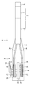
- Side view showing the configuration of the pulley provided with the wire fixing structure
- Perspective view showing the structure of a pulley provided with a wire fixing structure.
- Exploded perspective view showing the configuration of the same wire fixing structure
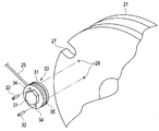
- Exploded perspective view showing a state in which the wire fixing structure is fixed to a pulley.
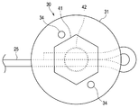
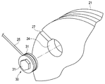
- Side view showing the configuration of the same wire fixing structure
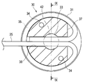
- Sectional view showing the configuration of the same wire fixing structure Sectional drawing showing the configuration of the wire fixing structure along the line IX-IX in FIG.
- FIG. 1 which shows the fixed state of the bending wire of the same stranded wire
- Side view showing a configuration of a wire fixing structure according to a first modification.
- Side view showing a configuration of a wire fixing structure according to a second modification.
- Side view showing the configuration of a wire fixing structure according to a third modification.
- Side view showing the configuration of a wire fixing structure according to a fourth modification.
- Partial sectional view showing a configuration in which an anchor member is provided on a curved wire according to a fifth modification.
- Exploded perspective view showing a state in which a wire fixing structure according to a sixth modification is fixed to a pulley.
- FIG. 1 is an overall perspective view showing a schematic configuration of an endoscope according to one embodiment of the present invention
- FIG. 2 is a schematic diagram of the endoscope schematically showing the inside of an operation unit
- FIG. 3 is provided with a wire fixing structure.
- 4 is a perspective view showing a configuration of a pulley provided with a wire fixing structure
- FIG. 5 is an exploded perspective view showing a configuration of the wire fixing structure
- FIG. 6 is a pulley having a wire fixing structure.
- 7 is a side view showing the configuration of the wire fixing structure
- FIG. 8 is a cross-sectional view showing the configuration of the wire fixing structure
- FIG. 9 is a view taken along the line IX-IX of FIG.
- FIG. 10 is a cross-sectional view illustrating the configuration of the wire fixing structure
- FIG. 10 is a diagram illustrating a fixed state of the curved wire of the stranded wire.
- the endoscope 1 mainly includes an insertion section 2, an operation section 3, a universal cord 4, an endoscope connector 5, and the like.
- the insertion section 2 is formed in an elongated shape and is inserted into a subject, and here is entirely formed by a multi-lumen tube.
- the insertion section 2 is formed by sequentially connecting a distal end portion 6, a bending portion 7 as an endoscope bending portion, and a flexible tube portion 8 from the distal end side, and has flexibility as a whole.
- the insertion part 2 here is a structure which can be made into a single use (disposable) type by being formed with a multi-lumen tube which can be manufactured at low cost.
- the distal end portion 6 of the insertion section 2 has a built-in image pickup unit, which is an image pickup apparatus having an image pickup device and the like, and an illumination optical system for irradiating illumination light forward (all are not shown).
- a built-in image pickup unit which is an image pickup apparatus having an image pickup device and the like, and an illumination optical system for irradiating illumination light forward (all are not shown).
- the form of the endoscope to which the present invention can be applied is not limited to the above-described example (an electronic endoscope having an imaging unit and the like), and other forms, for example, having no imaging unit Alternatively, a so-called fiber scope in which an image guide fiber is provided in the insertion section 2 may be used.
- the bending portion 7 receives the turning operation of the bending lever 13 for performing the bending operation among the operation members provided in the operation portion 3, and moves along the first direction and the second direction opposite thereto.
- it is configured to be able to bend actively in two directions of up and down (UP and DOWN).
- the up and down (UP and DOWN) are the up and down directions in the endoscope image captured by the imaging unit.
- the bending portion 7 may be configured to actively bend not only in two directions of up and down (UP and DOWN) but also in four directions of up, down, left and right (UP, DOWN, LEFT and RIGHT).
- the flexible tube section 8 is configured to have flexibility so as to be passively flexible. Inside the flexible tube portion 8, in addition to the lumen for the treatment instrument insertion channel, extends from the imaging unit built in the distal end portion 6, and extends into the universal cord 4 through the operation portion 3. The light emitted from a lumen through which various signal lines are inserted or a light source device (not shown) as an external device is guided to an illumination window (not shown) provided on the distal end surface of the distal end portion 6. A lumen through which a light guide (not shown) is inserted is formed.
- the light source may be a mode in which a light emitter (for example, a light emitting diode (LED)) is provided inside the operation unit.
- a light emitter for example, a light emitting diode (LED)
- the light guide (not shown) is used to guide the light emitted from the LED in the operation unit to the illumination window of the distal end portion 6.
- a light-emitting body such as an LED may be provided inside the distal end portion 6, for example, at a position near the base end of the illumination window.
- the light emitted from the LED directly passes through the illumination window and illuminates the front of the distal end portion 6.
- a light guide (not shown) in the flexible tube portion 8 becomes unnecessary.
- a power supply line or the like for causing the LED provided at the distal end portion 6 to emit light is inserted through the lumen in the flexible tube portion 8.
- the operation unit 3 is a constituent unit that is provided continuously with the base end of the insertion unit 2 and includes a plurality of operation members and the like.
- the operation unit 3 includes a fold prevention unit 9, a grip unit 10, a plurality of operation members (13, 14, etc.), a treatment tool insertion unit 11, a suction valve 15, and the like.
- the bend preventing portion 9 is provided at a connection portion between the distal end portion of the operation portion 3 and the base end portion of the flexible tube portion 8, and covers the base end portion of the flexible tube portion 8, so that the endoscope 1 It is a protection member for preventing the flexible tube portion 8 from being unnecessarily sharply broken during use.
- the grip 10 is a housing that accommodates various components therein.
- the grip portion 10 is connected to the buckling prevention portion 9.
- the grip 10 is a part that is held by the user when the endoscope 1 is used.
- the plurality of operation members are provided on the outer surface of the grip portion 10 and are members for operating various functions of the endoscope 1.
- the plurality of operation members for example, in addition to the bending lever 13 for performing the bending operation of the bending portion 7 in the vertical direction, the operation members for performing the air / water supply operation and the suction operation, and the operations corresponding to the imaging unit and the illumination unit, respectively.
- the treatment instrument insertion section 11 has a treatment instrument insertion port (not shown) for inserting various treatment instruments (not shown), and has a treatment instrument insertion passage communicating with a treatment instrument insertion channel inside the operation section 3. It is a component.
- a forceps stopper 12 which is a lid member for opening and closing the treatment tool insertion opening and which is detachably (replaceable) with respect to the treatment tool insertion portion 11 is provided in the treatment tool insertion portion 11.
- the suction valve 15 is a connecting portion for connecting a suction pipe line to a suction device (not shown).
- the universal cord 4 is a hollow tubular member having flexibility and extending from the operation unit 3.
- the universal cord 4 is connected to various signal lines extending from the distal end portion 6 of the insertion portion 2 through the inside of the insertion portion 2 and through the inside of the operation portion 3 and a light source device (not shown) as an external device.
- a composite cable in which a tube for air supply and water supply from an air supply and water supply device (not shown) as an external device are inserted.
- the endoscope connector 5 is a connection member provided at the end of the universal cord 4 for ensuring connection with an external device.
- the endoscope connector 5 has an electric connector portion 16 for connecting a signal cable for connection to a video processor (not shown) as an external device on a side surface portion.
- the endoscope connector 5 includes a light guide bundle for connecting with a light source device (not shown) which is an external device, and a light source connector unit for connecting an electric cable (not shown) in which the various signal lines are combined. 17 and the like.
- two pulleys 21 are provided in the operation unit 3 so as to be rotatable around a shaft 22.
- the shaft body 22 is connected to the bending lever 13 provided in the operation unit 3, and is supported by a bearing member 23 fixed in the operation unit 3.
- a curved wire 25 as a pulling wire is wound around the two pulleys 21, inserted through the coil tube 26, and arranged from the operation section 3 to the insertion section 2.
- Each of the two pulleys 21 is provided with a wire fixing structure 30 for fixing the bending wire 25, which will be described later.
- the two bending wires 25 are connected to a bending piece (not shown) disposed in the bending section 7 of the insertion section 2. These two pulleys 21 rotate around the shaft 22 in conjunction with the rotation operation of the bending lever 13.
- the two bending wires 25 are pulled and relaxed, and the bending portion 7 is actively bent in two directions of up and down (UP and DOWN). Since the structure of the bending portion 7 is well known, a detailed description of members constituting the bending portion 7 is omitted.
- the endoscope 1 is provided with a wire fixing structure 30 for fixing the ends of the curved wires 25 to the respective side surfaces of two pulleys 21 provided in the operation unit 3. I have.
- the wire fixing structure 30 includes a fixing member 31 for fixing a substantially cylindrical wire, and a bolt 41 which is a wire pressing member as a fastening member screwed to the fixing member 31.
- the fixing member 31 has two holes 34 penetrating the side surface. Screws 32 are inserted into these two holes 34, respectively.
- the two screws 32 are screwed into two screw holes 28 formed on the side surface of the pulley 21.
- the fixing member 31 is fixed to the side surface of the pulley 21.
- the pulley 21 has a notch 27 formed in a part of the outer peripheral portion of the side surface to which the fixing member 31 is fixed.
- the curved wire 25 whose end is fixed to the fixing member 31 is wound around the outer periphery of the pulley 21 along the notch 27 of the pulley 21 and wound.
- the details of the wire fixing structure 30 for fixing the end of the curved wire 25 to the fixing member 31 will be described.
- the winding wire 25 is wound once while applying tension along a circumferential groove 35 formed on the outer peripheral portion of the fixing member 31, It is inserted into the fixing member 31 again.
- the fixing member 31 has a through-hole portion 36 that penetrates the outer peripheral portion linearly from the outer peripheral direction.
- the through hole 36 is formed to pass through the center of the fixing member 31 and communicates with a female screw hole 33 formed in a direction perpendicular to the through hole 36.
- the fixing member 31 is formed with a deep groove 37 having a shape in which the circumferential groove 35 opposite to the direction in which the curved wire 25 extends is linearly cut away.
- the deep groove 37 is for winding the bending wire 25 around the circumferential groove 35 and for easily bending and inserting the bent wire 25 into the through hole 36 again.
- one curved wire 25 is inserted into the through-hole portion 36 of the fixing member 31, and the curved wire 25 is wound around the outer peripheral portion of the fixing member 31 along the circumferential groove 35, and the curved wire 25 is wound. 25 is inserted into the through hole 36.
- the bending wire 25 is inserted into the through-hole portion 36 of the fixing member 31 to be a first portion provided therein, and a portion closer to the end portion than the first portion is extended from the through-hole portion 36.
- a second portion is wound around the outer peripheral portion of the fixing member 36. After the second portion is wound around the fixing member 36, the end portion which is inserted into the through-hole portion 36 and is provided again is the third portion. Part.
- one bending wire 25 is in a state where the middle part and the end part are juxtaposed in the through-hole part 36.
- the male screw portion 42 of the bolt 41 is screwed into the female screw hole portion 33 and tightened, one curved wire 25 whose middle portion and end portion are inserted in the through hole portion 36 is pressed. And is fixed to the fixing member 31.
- the bolt 41 is inserted into the female screw hole 33 and screwed, and the first and third portions of the curved wire 25 provided in the through hole 36 are pressed and fixed in the through hole 36. You.
- the wire fixing structure 30 of the present embodiment is configured such that one curved wire 25 is wound around the fixing member 31 by applying tension around the outer periphery thereof, and the through-hole portion through which the middle and the end of the curved wire 25 are inserted.
- the fixing strength of the bending wire 25 to the fixing member 31 is increased by tightening with the bolt 41.
- the endoscope 1 is configured such that the bending wire 25 that is the pulling wire that bends the bending portion 7 of the insertion portion 2 can be stably fixed to the pulley 21 without loosening.
- the structure including the structure 30 is provided.
- FIG. 11 is a side view showing the configuration of the wire fixing structure of the first modification. As shown in FIG. 11, the bending wire 25 may be wound around the fixing member 31 in a figure eight shape.
- the bending wire 25 is inserted into the through hole 36 of the fixing member 31, wound around the outer periphery halfway along the circumferential groove 35 of the fixing member 31, and inserted again into the through hole 36. . Then, the bending wire 25 is further wound around the other outer circumference halfway along the circumferential groove 35 of the fixing member 31, and the end is inserted into the through hole 36.
- the bending wire 25 is inserted into the through hole 36 of the fixing member 31 to be a first portion provided therein, and a portion closer to the end portion than the first portion is extended from the through hole 36.
- a second portion is wound around one half of the outer peripheral portion of the fixing member 36. After the second portion is wound around the fixing member 36, the second portion is inserted into the through-hole portion 36 again to be internally provided. This is the third part.
- the bending wire 25 has a portion closer to the end portion than the third portion extending from the through-hole portion 36 to become a fourth portion wound around the other half of the outer peripheral portion of the fixing member 31. After the fourth portion is wound around the fixing member 31, the end portion which is inserted into the through-hole portion 36 and provided therein again becomes the fifth portion.
- the bolt 41 is inserted and screwed into the female screw hole 33, and the first, third, and fifth portions of the curved wire 25 provided inside the through hole 36 are pressed in the through hole 36. Fixed.
- the curved wire 25 is inserted into the through-hole portion 36 of the fixing member 31, and the curved wire 25 is more firmly fixed to the fixing member 31 by tightening the three portions with the bolts 41. Can be.
- FIG. 12 is a side view showing the configuration of the wire fixing structure according to the second modification.
- the bending wire 25 may have a configuration in which only one half of the outer circumference of the fixing member 31 is wound. Also in this case, similarly to the above-described embodiment, two locations of the curved wire 25 are inserted into the through hole 36 of the fixing member 31, and these two locations are fastened to the bolts 41.
- FIG. 13 is a side view illustrating a configuration of a wire fixing structure according to a third modification.
- the bending wire 25 may be configured to be inserted into the through-hole portion 36 of the fixing member 31, then folded and inserted into the through-hole portion 36 and fixed. Also in this case, similarly to the above-described embodiment and the second modification, two portions of the curved wire 25 are inserted into the through-hole portion 36 of the fixing member 31, and these two portions are fastened to the bolt 41. .
- FIG. 14 is a side view illustrating a configuration of a wire fixing structure according to a fourth modification.
- the fixing member 31 is not limited to a cylindrical shape, but may be a polygonal shape having a non-circular cross section, for example, a quadrangular prism shape having a quadrangular cross section as shown in FIG. In this case, since the bending wire 25 is bent at the four corners of the fixing member 31, more frictional force is generated, and the bending wire 25 can be firmly fixed to the fixing member 31.
- FIG. 15 is a partial cross-sectional view illustrating a configuration in which an anchor member is provided on a curved wire according to a fifth modification. As shown in FIG. 15, a configuration in which an anchor member 43 in which two concave and convex portions 44 are formed on the curved wire 25 may be provided.
- These two anchor members 43 are arranged in the through hole 36 of the fixing member 31, and a tension in the direction A in the drawing is generated in one of the bending wires 25 in the through hole 36, and the other of the bending wires 25 is Even if the wire is pulled in the opposite direction B, the curved wire 25 is prevented from being loosened by engaging and locking the concave and convex portions 44 formed on the anchor member 43.
- FIG. 16 is an exploded perspective view showing a state where the wire fixing structure of the sixth modification is fixed to the pulley. As shown in FIG. 16, in the configuration in which the fixing member 31 of the wire fixing structure 30 is mounted on the pulley 21, a columnar concave portion 24 is formed in the pulley 21, even if the fixing member 31 is not screwed. It may be fitted and mounted.
- the present invention is not limited to the above-described embodiment, and it is needless to say that various modifications and applications can be made without departing from the gist of the invention. Further, the embodiments include inventions at various stages, and various inventions can be extracted by appropriately combining a plurality of disclosed constituent elements.
Landscapes
- Health & Medical Sciences (AREA)
- Life Sciences & Earth Sciences (AREA)
- Surgery (AREA)
- Biomedical Technology (AREA)
- Medical Informatics (AREA)
- Optics & Photonics (AREA)
- Pathology (AREA)
- Radiology & Medical Imaging (AREA)
- Biophysics (AREA)
- Engineering & Computer Science (AREA)
- Physics & Mathematics (AREA)
- Heart & Thoracic Surgery (AREA)
- Nuclear Medicine, Radiotherapy & Molecular Imaging (AREA)
- Molecular Biology (AREA)
- Animal Behavior & Ethology (AREA)
- General Health & Medical Sciences (AREA)
- Public Health (AREA)
- Veterinary Medicine (AREA)
- Endoscopes (AREA)
- Instruments For Viewing The Inside Of Hollow Bodies (AREA)
Abstract
Selon la présente invention, cette structure de fixation de fil (30) comprend : un élément de fixation de fil fixé à une poulie (21) qui tourne de sorte à tirer et desserrer un fil (25), et ayant un premier trou qui passe à travers une partie circonférentielle externe et dans lequel le fil est inséré, et un deuxième trou qui est formé dans une direction perpendiculaire au premier trou et communique avec le premier trou, le fil étant enroulé sur la partie circonférentielle externe de l'élément de fixation de fil ; et un élément de fixation (41) inséré dans le deuxième trou et pressant et fixant le fil disposé à l'intérieur du premier trou. Le fil a : une première section insérée dans le premier trou ; une deuxième section s'étendant à partir du premier trou et enroulée sur la partie circonférentielle externe ; et une troisième section qui est insérée une fois dans le premier trou une fois que la deuxième section est enroulée sur la partie circonférentielle externe. L'élément de fixation est inséré dans le deuxième trou, et presse et fixe la première section et la troisième section à l'intérieur du premier trou.
Priority Applications (1)
| Application Number | Priority Date | Filing Date | Title |
|---|---|---|---|
| US17/096,247 US11950764B2 (en) | 2018-06-28 | 2020-11-12 | Wire fixing structure and endoscope |
Applications Claiming Priority (2)
| Application Number | Priority Date | Filing Date | Title |
|---|---|---|---|
| JP2018122871A JP2021182017A (ja) | 2018-06-28 | 2018-06-28 | ワイヤ固定構造および内視鏡 |
| JP2018-122871 | 2018-06-28 |
Related Child Applications (1)
| Application Number | Title | Priority Date | Filing Date |
|---|---|---|---|
| US17/096,247 Continuation US11950764B2 (en) | 2018-06-28 | 2020-11-12 | Wire fixing structure and endoscope |
Publications (1)
| Publication Number | Publication Date |
|---|---|
| WO2020003594A1 true WO2020003594A1 (fr) | 2020-01-02 |
Family
ID=68986282
Family Applications (1)
| Application Number | Title | Priority Date | Filing Date |
|---|---|---|---|
| PCT/JP2019/006311 Ceased WO2020003594A1 (fr) | 2018-06-28 | 2019-02-20 | Structure de fixation de fil et endoscope |
Country Status (3)
| Country | Link |
|---|---|
| US (1) | US11950764B2 (fr) |
| JP (1) | JP2021182017A (fr) |
| WO (1) | WO2020003594A1 (fr) |
Cited By (4)
| Publication number | Priority date | Publication date | Assignee | Title |
|---|---|---|---|---|
| CN113349715A (zh) * | 2020-03-02 | 2021-09-07 | 南微医学科技股份有限公司 | 转向固定头、导管转向牵引机构、转向装置和内镜 |
| CN115227183A (zh) * | 2022-08-30 | 2022-10-25 | 湖南省华芯医疗器械有限公司 | 牵引轮、牵引绳调节机构、操作手柄及内窥镜 |
| CN116649869A (zh) * | 2023-06-15 | 2023-08-29 | 常州乐奥医疗科技股份有限公司 | 一种内窥镜操作手柄 |
| WO2026004142A1 (fr) * | 2024-06-28 | 2026-01-02 | オリンパスメディカルシステムズ株式会社 | Mécanisme d'actionnement d'appareil d'insertion et appareil d'insertion |
Families Citing this family (7)
| Publication number | Priority date | Publication date | Assignee | Title |
|---|---|---|---|---|
| US11974722B2 (en) * | 2019-10-07 | 2024-05-07 | Boston Scientific Scimed, Inc. | Endoscopic device with interchangeable shaft |
| GB2610648B (en) * | 2021-09-14 | 2023-09-06 | I Q Endoscopes Ltd | Endoscopy system & elements thereof |
| US20230131784A1 (en) * | 2021-10-22 | 2023-04-27 | Gyrus Acmi, Inc. D/B/A Olympus Surgical Technologies America | Endoscopic articulation device |
| WO2023101913A1 (fr) * | 2021-12-01 | 2023-06-08 | Noah Medical Corporation | Systèmes et procédés de conception d'extrémité proximale d'endoscope |
| CN114886365A (zh) * | 2022-05-20 | 2022-08-12 | 深圳英术生命科技有限公司 | 一种电子内窥镜 |
| JP2025137457A (ja) * | 2024-03-06 | 2025-09-19 | オリンパスメディカルシステムズ株式会社 | 内視鏡 |
| CN118177696B (zh) * | 2024-05-17 | 2024-08-09 | 湖南省华芯医疗器械有限公司 | 一种用于内窥镜的牵引机构以及装配工装、方法和内窥镜 |
Citations (4)
| Publication number | Priority date | Publication date | Assignee | Title |
|---|---|---|---|---|
| JPH04124103U (ja) * | 1991-04-24 | 1992-11-11 | オリンパス光学工業株式会社 | 内視鏡 |
| JPH04367643A (ja) * | 1991-06-14 | 1992-12-18 | Machida Endscope Co Ltd | 体腔内診断装置用操作ワイヤの連結構造 |
| JPH06315460A (ja) * | 1993-05-10 | 1994-11-15 | Olympus Optical Co Ltd | 内視鏡 |
| JP2004350866A (ja) * | 2003-05-28 | 2004-12-16 | Olympus Corp | 内視鏡装置 |
Family Cites Families (4)
| Publication number | Priority date | Publication date | Assignee | Title |
|---|---|---|---|---|
| US4941454A (en) * | 1989-10-05 | 1990-07-17 | Welch Allyn, Inc. | Servo actuated steering mechanism for borescope or endoscope |
| US5569157A (en) | 1993-05-07 | 1996-10-29 | Olympus Optical Co., Ltd. | Endoscope |
| JP3278840B2 (ja) | 1993-12-22 | 2002-04-30 | 富士写真光機株式会社 | 内視鏡の湾曲操作装置 |
| US7285088B2 (en) | 2003-05-13 | 2007-10-23 | Olympus Corporation | Endoscope apparatus |
-
2018
- 2018-06-28 JP JP2018122871A patent/JP2021182017A/ja active Pending
-
2019
- 2019-02-20 WO PCT/JP2019/006311 patent/WO2020003594A1/fr not_active Ceased
-
2020
- 2020-11-12 US US17/096,247 patent/US11950764B2/en active Active
Patent Citations (4)
| Publication number | Priority date | Publication date | Assignee | Title |
|---|---|---|---|---|
| JPH04124103U (ja) * | 1991-04-24 | 1992-11-11 | オリンパス光学工業株式会社 | 内視鏡 |
| JPH04367643A (ja) * | 1991-06-14 | 1992-12-18 | Machida Endscope Co Ltd | 体腔内診断装置用操作ワイヤの連結構造 |
| JPH06315460A (ja) * | 1993-05-10 | 1994-11-15 | Olympus Optical Co Ltd | 内視鏡 |
| JP2004350866A (ja) * | 2003-05-28 | 2004-12-16 | Olympus Corp | 内視鏡装置 |
Cited By (7)
| Publication number | Priority date | Publication date | Assignee | Title |
|---|---|---|---|---|
| CN113349715A (zh) * | 2020-03-02 | 2021-09-07 | 南微医学科技股份有限公司 | 转向固定头、导管转向牵引机构、转向装置和内镜 |
| WO2021175091A1 (fr) * | 2020-03-02 | 2021-09-10 | 南微医学科技股份有限公司 | Tête de fixation de guidage, mécanisme de traction de guidage de cathéter, dispositif de guidage et endoscope |
| CN115227183A (zh) * | 2022-08-30 | 2022-10-25 | 湖南省华芯医疗器械有限公司 | 牵引轮、牵引绳调节机构、操作手柄及内窥镜 |
| CN115227183B (zh) * | 2022-08-30 | 2023-05-16 | 湖南省华芯医疗器械有限公司 | 牵引轮、牵引绳调节机构、操作手柄及内窥镜 |
| CN116649869A (zh) * | 2023-06-15 | 2023-08-29 | 常州乐奥医疗科技股份有限公司 | 一种内窥镜操作手柄 |
| CN116649869B (zh) * | 2023-06-15 | 2023-11-14 | 常州乐奥医疗科技股份有限公司 | 一种内窥镜操作手柄 |
| WO2026004142A1 (fr) * | 2024-06-28 | 2026-01-02 | オリンパスメディカルシステムズ株式会社 | Mécanisme d'actionnement d'appareil d'insertion et appareil d'insertion |
Also Published As
| Publication number | Publication date |
|---|---|
| US11950764B2 (en) | 2024-04-09 |
| JP2021182017A (ja) | 2021-11-25 |
| US20210059506A1 (en) | 2021-03-04 |
Similar Documents
| Publication | Publication Date | Title |
|---|---|---|
| WO2020003594A1 (fr) | Structure de fixation de fil et endoscope | |
| US11622674B2 (en) | Articulated tip part for an endoscope | |
| US11540703B2 (en) | Steerable micro-endoscope | |
| US20230108741A1 (en) | Insertion device and operation portion unit | |
| US20170079505A1 (en) | Endoscope bending portion and endoscope | |
| US11311179B2 (en) | Endoscope | |
| EP3158913B1 (fr) | Endoscope | |
| CN111065312B (zh) | 内窥镜的插入部和内窥镜 | |
| CN110545708B (zh) | 内窥镜弯曲部和内窥镜 | |
| JP2011177383A (ja) | 内視鏡の操作ワイヤ連結装置及び内視鏡 | |
| US20130217963A1 (en) | Endoscope auxiliary instrument and endoscope | |
| CN110960177A (zh) | 用于内窥镜的铰接式端头部 | |
| JP6271098B1 (ja) | 医療用オーバーチューブ | |
| JP5457318B2 (ja) | 内視鏡 | |
| US9339168B2 (en) | Endoscope operation portion structure | |
| JP6796215B2 (ja) | 内視鏡の先端部および内視鏡 | |
| JP6731554B2 (ja) | 内視鏡 | |
| WO2017122399A1 (fr) | Endoscope | |
| JP2004016725A (ja) | 超音波内視鏡 | |
| US20220313063A1 (en) | Bending operation mechanism for endoscope and endoscope | |
| US20060264787A1 (en) | Ultrasonic treatment apparatus | |
| JPWO2019017112A1 (ja) | 内視鏡 | |
| WO2020031378A1 (fr) | Endoscope | |
| JP2012045045A (ja) | 内視鏡 |
Legal Events
| Date | Code | Title | Description |
|---|---|---|---|
| 121 | Ep: the epo has been informed by wipo that ep was designated in this application |
Ref document number: 19826671 Country of ref document: EP Kind code of ref document: A1 |
|
| NENP | Non-entry into the national phase |
Ref country code: DE |
|
| 122 | Ep: pct application non-entry in european phase |
Ref document number: 19826671 Country of ref document: EP Kind code of ref document: A1 |
|
| NENP | Non-entry into the national phase |
Ref country code: JP |