WO2020003594A1 - ワイヤ固定構造および内視鏡 - Google Patents
ワイヤ固定構造および内視鏡 Download PDFInfo
- Publication number
- WO2020003594A1 WO2020003594A1 PCT/JP2019/006311 JP2019006311W WO2020003594A1 WO 2020003594 A1 WO2020003594 A1 WO 2020003594A1 JP 2019006311 W JP2019006311 W JP 2019006311W WO 2020003594 A1 WO2020003594 A1 WO 2020003594A1
- Authority
- WO
- WIPO (PCT)
- Prior art keywords
- hole
- wire
- wire fixing
- bending
- fixing structure
- Prior art date
- Legal status (The legal status is an assumption and is not a legal conclusion. Google has not performed a legal analysis and makes no representation as to the accuracy of the status listed.)
- Ceased
Links
Images


Classifications
-
- A—HUMAN NECESSITIES
- A61—MEDICAL OR VETERINARY SCIENCE; HYGIENE
- A61B—DIAGNOSIS; SURGERY; IDENTIFICATION
- A61B1/00—Instruments for performing medical examinations of the interior of cavities or tubes of the body by visual or photographical inspection, e.g. endoscopes; Illuminating arrangements therefor
- A61B1/005—Flexible endoscopes
- A61B1/0051—Flexible endoscopes with controlled bending of insertion part
- A61B1/0052—Constructional details of control elements, e.g. handles
-
- A—HUMAN NECESSITIES
- A61—MEDICAL OR VETERINARY SCIENCE; HYGIENE
- A61B—DIAGNOSIS; SURGERY; IDENTIFICATION
- A61B1/00—Instruments for performing medical examinations of the interior of cavities or tubes of the body by visual or photographical inspection, e.g. endoscopes; Illuminating arrangements therefor
- A61B1/005—Flexible endoscopes
- A61B1/0051—Flexible endoscopes with controlled bending of insertion part
- A61B1/0057—Constructional details of force transmission elements, e.g. control wires
-
- A—HUMAN NECESSITIES
- A61—MEDICAL OR VETERINARY SCIENCE; HYGIENE
- A61B—DIAGNOSIS; SURGERY; IDENTIFICATION
- A61B1/00—Instruments for performing medical examinations of the interior of cavities or tubes of the body by visual or photographical inspection, e.g. endoscopes; Illuminating arrangements therefor
- A61B1/00064—Constructional details of the endoscope body
- A61B1/00071—Insertion part of the endoscope body
- A61B1/0008—Insertion part of the endoscope body characterised by distal tip features
- A61B1/00098—Deflecting means for inserted tools
-
- G—PHYSICS
- G02—OPTICS
- G02B—OPTICAL ELEMENTS, SYSTEMS OR APPARATUS
- G02B23/00—Telescopes, e.g. binoculars; Periscopes; Instruments for viewing the inside of hollow bodies; Viewfinders; Optical aiming or sighting devices
- G02B23/24—Instruments or systems for viewing the inside of hollow bodies, e.g. fibrescopes
- G02B23/2476—Non-optical details, e.g. housings, mountings, supports
Definitions
- the present invention relates to a wire fixing structure for fixing a wire for operating a bending portion provided in an insertion portion and an endoscope.
- the endoscope has an insertion portion that is formed in an elongated tubular shape and is inserted into a lumen according to the observation target in order to support various observation targets. It is known that an insertion portion of the endoscope is provided with a curved portion for changing a viewing field direction.
- the bending portion of the endoscope is bent by rotating an operation member such as a bending lever provided on the operation portion.
- the endoscope is provided with a rotatable pulley connected to a bending lever in the operation section, and a pulling wire for operating the bending section is wound around the pulley.
- the present invention has been made in view of the above-described problem, and provides a wire fixing structure and an endoscope that can stably fix a pulling wire that curves a curved portion to a pulley without loosening.
- the purpose is to:
- the wire fixing structure includes a wire for operating a bending portion of an endoscope and a pulley that is attached to a pulley that pulls and relaxes the wire by rotating, and a first hole through which the wire is inserted. And a second hole formed in a direction orthogonal to the first hole and communicating with the first hole, and a wire fixing member around which the wire is wound around an outer peripheral portion; A fastening member that is inserted into the hole and presses and fixes the wire disposed inside the first hole.
- the wire is inserted through the first hole and A first portion provided, a second portion extending from the first hole and wound around the outer peripheral portion, and after the second portion is wound around the outer peripheral portion, And a third portion inserted through the first hole and internally provided, wherein the fastening member is inserted into the second hole. And said first portion and said third portion and fixed to pressing in the first hole portion.
- An endoscope includes a wire for bending a bending portion of the endoscope and a pulley that is attached to a pulley that pulls and relaxes the wire by rotating, and a first hole through which the wire is inserted. And a second hole formed in a direction orthogonal to the first hole and communicating with the first hole, and a wire fixing member around which the wire is wound around an outer peripheral portion; A fastening member that is inserted into the hole and presses and fixes the wire disposed inside the first hole.
- the wire is inserted through the first hole and A first portion provided, a second portion extending from the first hole and wound around the outer peripheral portion, and after the second portion is wound around the outer peripheral portion, A third portion inserted through the first hole and internally provided, wherein the fastening member is inserted into the second hole and And said third portion and the first portion has a wire fixing structure for fixing by pressing in the first hole portion.
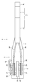
- FIG. 1 is an overall perspective view illustrating a schematic configuration of an endoscope according to one embodiment of the present invention.
- the schematic diagram of the endoscope schematically showing the inside of the operation unit
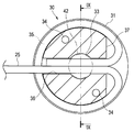
- Side view showing the configuration of the pulley provided with the wire fixing structure
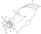
- Perspective view showing the structure of a pulley provided with a wire fixing structure.
- Exploded perspective view showing the configuration of the same wire fixing structure
- Exploded perspective view showing a state in which the wire fixing structure is fixed to a pulley.
- Side view showing the configuration of the same wire fixing structure
- Sectional view showing the configuration of the same wire fixing structure Sectional drawing showing the configuration of the wire fixing structure along the line IX-IX in FIG.
- FIG. 1 which shows the fixed state of the bending wire of the same stranded wire
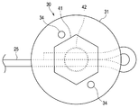
- Side view showing a configuration of a wire fixing structure according to a first modification.
- Side view showing a configuration of a wire fixing structure according to a second modification.
- Side view showing the configuration of a wire fixing structure according to a third modification.
- Side view showing the configuration of a wire fixing structure according to a fourth modification.
- Partial sectional view showing a configuration in which an anchor member is provided on a curved wire according to a fifth modification.
- Exploded perspective view showing a state in which a wire fixing structure according to a sixth modification is fixed to a pulley.
- FIG. 1 is an overall perspective view showing a schematic configuration of an endoscope according to one embodiment of the present invention
- FIG. 2 is a schematic diagram of the endoscope schematically showing the inside of an operation unit
- FIG. 3 is provided with a wire fixing structure.
- 4 is a perspective view showing a configuration of a pulley provided with a wire fixing structure
- FIG. 5 is an exploded perspective view showing a configuration of the wire fixing structure
- FIG. 6 is a pulley having a wire fixing structure.
- 7 is a side view showing the configuration of the wire fixing structure
- FIG. 8 is a cross-sectional view showing the configuration of the wire fixing structure
- FIG. 9 is a view taken along the line IX-IX of FIG.
- FIG. 10 is a cross-sectional view illustrating the configuration of the wire fixing structure
- FIG. 10 is a diagram illustrating a fixed state of the curved wire of the stranded wire.
- the endoscope 1 mainly includes an insertion section 2, an operation section 3, a universal cord 4, an endoscope connector 5, and the like.
- the insertion section 2 is formed in an elongated shape and is inserted into a subject, and here is entirely formed by a multi-lumen tube.
- the insertion section 2 is formed by sequentially connecting a distal end portion 6, a bending portion 7 as an endoscope bending portion, and a flexible tube portion 8 from the distal end side, and has flexibility as a whole.
- the insertion part 2 here is a structure which can be made into a single use (disposable) type by being formed with a multi-lumen tube which can be manufactured at low cost.
- the distal end portion 6 of the insertion section 2 has a built-in image pickup unit, which is an image pickup apparatus having an image pickup device and the like, and an illumination optical system for irradiating illumination light forward (all are not shown).
- a built-in image pickup unit which is an image pickup apparatus having an image pickup device and the like, and an illumination optical system for irradiating illumination light forward (all are not shown).
- the form of the endoscope to which the present invention can be applied is not limited to the above-described example (an electronic endoscope having an imaging unit and the like), and other forms, for example, having no imaging unit Alternatively, a so-called fiber scope in which an image guide fiber is provided in the insertion section 2 may be used.
- the bending portion 7 receives the turning operation of the bending lever 13 for performing the bending operation among the operation members provided in the operation portion 3, and moves along the first direction and the second direction opposite thereto.
- it is configured to be able to bend actively in two directions of up and down (UP and DOWN).
- the up and down (UP and DOWN) are the up and down directions in the endoscope image captured by the imaging unit.
- the bending portion 7 may be configured to actively bend not only in two directions of up and down (UP and DOWN) but also in four directions of up, down, left and right (UP, DOWN, LEFT and RIGHT).
- the flexible tube section 8 is configured to have flexibility so as to be passively flexible. Inside the flexible tube portion 8, in addition to the lumen for the treatment instrument insertion channel, extends from the imaging unit built in the distal end portion 6, and extends into the universal cord 4 through the operation portion 3. The light emitted from a lumen through which various signal lines are inserted or a light source device (not shown) as an external device is guided to an illumination window (not shown) provided on the distal end surface of the distal end portion 6. A lumen through which a light guide (not shown) is inserted is formed.
- the light source may be a mode in which a light emitter (for example, a light emitting diode (LED)) is provided inside the operation unit.
- a light emitter for example, a light emitting diode (LED)
- the light guide (not shown) is used to guide the light emitted from the LED in the operation unit to the illumination window of the distal end portion 6.
- a light-emitting body such as an LED may be provided inside the distal end portion 6, for example, at a position near the base end of the illumination window.
- the light emitted from the LED directly passes through the illumination window and illuminates the front of the distal end portion 6.
- a light guide (not shown) in the flexible tube portion 8 becomes unnecessary.
- a power supply line or the like for causing the LED provided at the distal end portion 6 to emit light is inserted through the lumen in the flexible tube portion 8.
- the operation unit 3 is a constituent unit that is provided continuously with the base end of the insertion unit 2 and includes a plurality of operation members and the like.
- the operation unit 3 includes a fold prevention unit 9, a grip unit 10, a plurality of operation members (13, 14, etc.), a treatment tool insertion unit 11, a suction valve 15, and the like.
- the bend preventing portion 9 is provided at a connection portion between the distal end portion of the operation portion 3 and the base end portion of the flexible tube portion 8, and covers the base end portion of the flexible tube portion 8, so that the endoscope 1 It is a protection member for preventing the flexible tube portion 8 from being unnecessarily sharply broken during use.
- the grip 10 is a housing that accommodates various components therein.
- the grip portion 10 is connected to the buckling prevention portion 9.
- the grip 10 is a part that is held by the user when the endoscope 1 is used.
- the plurality of operation members are provided on the outer surface of the grip portion 10 and are members for operating various functions of the endoscope 1.
- the plurality of operation members for example, in addition to the bending lever 13 for performing the bending operation of the bending portion 7 in the vertical direction, the operation members for performing the air / water supply operation and the suction operation, and the operations corresponding to the imaging unit and the illumination unit, respectively.
- the treatment instrument insertion section 11 has a treatment instrument insertion port (not shown) for inserting various treatment instruments (not shown), and has a treatment instrument insertion passage communicating with a treatment instrument insertion channel inside the operation section 3. It is a component.
- a forceps stopper 12 which is a lid member for opening and closing the treatment tool insertion opening and which is detachably (replaceable) with respect to the treatment tool insertion portion 11 is provided in the treatment tool insertion portion 11.
- the suction valve 15 is a connecting portion for connecting a suction pipe line to a suction device (not shown).
- the universal cord 4 is a hollow tubular member having flexibility and extending from the operation unit 3.
- the universal cord 4 is connected to various signal lines extending from the distal end portion 6 of the insertion portion 2 through the inside of the insertion portion 2 and through the inside of the operation portion 3 and a light source device (not shown) as an external device.
- a composite cable in which a tube for air supply and water supply from an air supply and water supply device (not shown) as an external device are inserted.
- the endoscope connector 5 is a connection member provided at the end of the universal cord 4 for ensuring connection with an external device.
- the endoscope connector 5 has an electric connector portion 16 for connecting a signal cable for connection to a video processor (not shown) as an external device on a side surface portion.
- the endoscope connector 5 includes a light guide bundle for connecting with a light source device (not shown) which is an external device, and a light source connector unit for connecting an electric cable (not shown) in which the various signal lines are combined. 17 and the like.
- two pulleys 21 are provided in the operation unit 3 so as to be rotatable around a shaft 22.
- the shaft body 22 is connected to the bending lever 13 provided in the operation unit 3, and is supported by a bearing member 23 fixed in the operation unit 3.
- a curved wire 25 as a pulling wire is wound around the two pulleys 21, inserted through the coil tube 26, and arranged from the operation section 3 to the insertion section 2.
- Each of the two pulleys 21 is provided with a wire fixing structure 30 for fixing the bending wire 25, which will be described later.
- the two bending wires 25 are connected to a bending piece (not shown) disposed in the bending section 7 of the insertion section 2. These two pulleys 21 rotate around the shaft 22 in conjunction with the rotation operation of the bending lever 13.
- the two bending wires 25 are pulled and relaxed, and the bending portion 7 is actively bent in two directions of up and down (UP and DOWN). Since the structure of the bending portion 7 is well known, a detailed description of members constituting the bending portion 7 is omitted.
- the endoscope 1 is provided with a wire fixing structure 30 for fixing the ends of the curved wires 25 to the respective side surfaces of two pulleys 21 provided in the operation unit 3. I have.
- the wire fixing structure 30 includes a fixing member 31 for fixing a substantially cylindrical wire, and a bolt 41 which is a wire pressing member as a fastening member screwed to the fixing member 31.
- the fixing member 31 has two holes 34 penetrating the side surface. Screws 32 are inserted into these two holes 34, respectively.
- the two screws 32 are screwed into two screw holes 28 formed on the side surface of the pulley 21.
- the fixing member 31 is fixed to the side surface of the pulley 21.
- the pulley 21 has a notch 27 formed in a part of the outer peripheral portion of the side surface to which the fixing member 31 is fixed.
- the curved wire 25 whose end is fixed to the fixing member 31 is wound around the outer periphery of the pulley 21 along the notch 27 of the pulley 21 and wound.
- the details of the wire fixing structure 30 for fixing the end of the curved wire 25 to the fixing member 31 will be described.
- the winding wire 25 is wound once while applying tension along a circumferential groove 35 formed on the outer peripheral portion of the fixing member 31, It is inserted into the fixing member 31 again.
- the fixing member 31 has a through-hole portion 36 that penetrates the outer peripheral portion linearly from the outer peripheral direction.
- the through hole 36 is formed to pass through the center of the fixing member 31 and communicates with a female screw hole 33 formed in a direction perpendicular to the through hole 36.
- the fixing member 31 is formed with a deep groove 37 having a shape in which the circumferential groove 35 opposite to the direction in which the curved wire 25 extends is linearly cut away.
- the deep groove 37 is for winding the bending wire 25 around the circumferential groove 35 and for easily bending and inserting the bent wire 25 into the through hole 36 again.
- one curved wire 25 is inserted into the through-hole portion 36 of the fixing member 31, and the curved wire 25 is wound around the outer peripheral portion of the fixing member 31 along the circumferential groove 35, and the curved wire 25 is wound. 25 is inserted into the through hole 36.
- the bending wire 25 is inserted into the through-hole portion 36 of the fixing member 31 to be a first portion provided therein, and a portion closer to the end portion than the first portion is extended from the through-hole portion 36.
- a second portion is wound around the outer peripheral portion of the fixing member 36. After the second portion is wound around the fixing member 36, the end portion which is inserted into the through-hole portion 36 and is provided again is the third portion. Part.
- one bending wire 25 is in a state where the middle part and the end part are juxtaposed in the through-hole part 36.
- the male screw portion 42 of the bolt 41 is screwed into the female screw hole portion 33 and tightened, one curved wire 25 whose middle portion and end portion are inserted in the through hole portion 36 is pressed. And is fixed to the fixing member 31.
- the bolt 41 is inserted into the female screw hole 33 and screwed, and the first and third portions of the curved wire 25 provided in the through hole 36 are pressed and fixed in the through hole 36. You.
- the wire fixing structure 30 of the present embodiment is configured such that one curved wire 25 is wound around the fixing member 31 by applying tension around the outer periphery thereof, and the through-hole portion through which the middle and the end of the curved wire 25 are inserted.
- the fixing strength of the bending wire 25 to the fixing member 31 is increased by tightening with the bolt 41.
- the endoscope 1 is configured such that the bending wire 25 that is the pulling wire that bends the bending portion 7 of the insertion portion 2 can be stably fixed to the pulley 21 without loosening.
- the structure including the structure 30 is provided.
- FIG. 11 is a side view showing the configuration of the wire fixing structure of the first modification. As shown in FIG. 11, the bending wire 25 may be wound around the fixing member 31 in a figure eight shape.
- the bending wire 25 is inserted into the through hole 36 of the fixing member 31, wound around the outer periphery halfway along the circumferential groove 35 of the fixing member 31, and inserted again into the through hole 36. . Then, the bending wire 25 is further wound around the other outer circumference halfway along the circumferential groove 35 of the fixing member 31, and the end is inserted into the through hole 36.
- the bending wire 25 is inserted into the through hole 36 of the fixing member 31 to be a first portion provided therein, and a portion closer to the end portion than the first portion is extended from the through hole 36.
- a second portion is wound around one half of the outer peripheral portion of the fixing member 36. After the second portion is wound around the fixing member 36, the second portion is inserted into the through-hole portion 36 again to be internally provided. This is the third part.
- the bending wire 25 has a portion closer to the end portion than the third portion extending from the through-hole portion 36 to become a fourth portion wound around the other half of the outer peripheral portion of the fixing member 31. After the fourth portion is wound around the fixing member 31, the end portion which is inserted into the through-hole portion 36 and provided therein again becomes the fifth portion.
- the bolt 41 is inserted and screwed into the female screw hole 33, and the first, third, and fifth portions of the curved wire 25 provided inside the through hole 36 are pressed in the through hole 36. Fixed.
- the curved wire 25 is inserted into the through-hole portion 36 of the fixing member 31, and the curved wire 25 is more firmly fixed to the fixing member 31 by tightening the three portions with the bolts 41. Can be.
- FIG. 12 is a side view showing the configuration of the wire fixing structure according to the second modification.
- the bending wire 25 may have a configuration in which only one half of the outer circumference of the fixing member 31 is wound. Also in this case, similarly to the above-described embodiment, two locations of the curved wire 25 are inserted into the through hole 36 of the fixing member 31, and these two locations are fastened to the bolts 41.
- FIG. 13 is a side view illustrating a configuration of a wire fixing structure according to a third modification.
- the bending wire 25 may be configured to be inserted into the through-hole portion 36 of the fixing member 31, then folded and inserted into the through-hole portion 36 and fixed. Also in this case, similarly to the above-described embodiment and the second modification, two portions of the curved wire 25 are inserted into the through-hole portion 36 of the fixing member 31, and these two portions are fastened to the bolt 41. .
- FIG. 14 is a side view illustrating a configuration of a wire fixing structure according to a fourth modification.
- the fixing member 31 is not limited to a cylindrical shape, but may be a polygonal shape having a non-circular cross section, for example, a quadrangular prism shape having a quadrangular cross section as shown in FIG. In this case, since the bending wire 25 is bent at the four corners of the fixing member 31, more frictional force is generated, and the bending wire 25 can be firmly fixed to the fixing member 31.
- FIG. 15 is a partial cross-sectional view illustrating a configuration in which an anchor member is provided on a curved wire according to a fifth modification. As shown in FIG. 15, a configuration in which an anchor member 43 in which two concave and convex portions 44 are formed on the curved wire 25 may be provided.
- These two anchor members 43 are arranged in the through hole 36 of the fixing member 31, and a tension in the direction A in the drawing is generated in one of the bending wires 25 in the through hole 36, and the other of the bending wires 25 is Even if the wire is pulled in the opposite direction B, the curved wire 25 is prevented from being loosened by engaging and locking the concave and convex portions 44 formed on the anchor member 43.
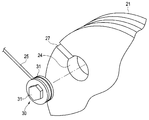
- FIG. 16 is an exploded perspective view showing a state where the wire fixing structure of the sixth modification is fixed to the pulley. As shown in FIG. 16, in the configuration in which the fixing member 31 of the wire fixing structure 30 is mounted on the pulley 21, a columnar concave portion 24 is formed in the pulley 21, even if the fixing member 31 is not screwed. It may be fitted and mounted.
- the present invention is not limited to the above-described embodiment, and it is needless to say that various modifications and applications can be made without departing from the gist of the invention. Further, the embodiments include inventions at various stages, and various inventions can be extracted by appropriately combining a plurality of disclosed constituent elements.
Landscapes
- Health & Medical Sciences (AREA)
- Life Sciences & Earth Sciences (AREA)
- Surgery (AREA)
- Biomedical Technology (AREA)
- Medical Informatics (AREA)
- Optics & Photonics (AREA)
- Pathology (AREA)
- Radiology & Medical Imaging (AREA)
- Biophysics (AREA)
- Engineering & Computer Science (AREA)
- Physics & Mathematics (AREA)
- Heart & Thoracic Surgery (AREA)
- Nuclear Medicine, Radiotherapy & Molecular Imaging (AREA)
- Molecular Biology (AREA)
- Animal Behavior & Ethology (AREA)
- General Health & Medical Sciences (AREA)
- Public Health (AREA)
- Veterinary Medicine (AREA)
- Endoscopes (AREA)
- Instruments For Viewing The Inside Of Hollow Bodies (AREA)
Abstract
ワイヤ固定構造30は、回動することでワイヤ25を牽引弛緩するプーリ21に装着され、外周部を貫通するように形成され、ワイヤが挿通する第1の孔部と、第1の孔部に対して直交する方向に形成されて連通する第2の孔部と、を有し、ワイヤが外周部に巻回されるワイヤ固定部材と、第2の孔部に挿入され、第1の孔部の内部に配設されたワイヤを押圧して固定する締結部材41と、を具備し、ワイヤは、第1の孔部に挿通して内設される第1部分と、第1の孔部から延出されて、外周部に巻きつけられる第2部分と、第2部分が外周部に巻回された後に、再度、第1の孔部に挿通して内設される第3部分と、を有し、締結部材41が第2の孔部に挿入されて、第1部分と第3部分とを第1の孔部内で押圧して固定する。
Description
本発明は、挿入部に設けられた湾曲部を操作するワイヤを固定するワイヤ固定構造および内視鏡に関する。
内視鏡は、様々な観察対象に対応するために、観察対象に応じて細長管状に形成されて管腔内に挿入される挿入部を有している。この内視鏡の挿入部には、観察視野方向を可変するための湾曲部が設けられたものが知られている。
この内視鏡の湾曲部は、操作部に設けられた湾曲レバーなどの操作部材を回動操作することによって湾曲される。また、内視鏡は、操作部内に湾曲レバーに接続されて回動自在なプーリが設けられており、このプーリに湾曲部を操作する牽引ワイヤが巻回されている。
このような構成は、例えば、日本国特開平7-178041号公報に開示されている。この日本国特開平7-178041号公報には、プーリの切欠部に嵌入する筒状のカラーに湾曲ワイヤである牽引ワイヤが挿入され、ネジによってワイヤ固定部材であるカラーをプーリに固定する内視鏡の湾曲操作操置が開示されている。
しかしながら、従来の内視鏡の湾曲操作操置に開示された牽引ワイヤの固定構造では、カラーに挿通した1本の牽引ワイヤをネジで押圧するだけであり、固定部材であるカラーに対して牽引ワイヤがずれて緩む問題が生じていた。
そこで、本発明は、上述した問題に鑑みてなされたものであって、湾曲部を湾曲する牽引ワイヤが緩むことなく安定的にプーリに固定することができるワイヤ固定構造および内視鏡を提供することを目的とする。
本発明の一態様のワイヤ固定構造は、内視鏡の湾曲部を湾曲操作するワイヤと、回動することで前記ワイヤを牽引弛緩するプーリに装着され、前記ワイヤが挿通する第1の孔部と、前記第1の孔部に対して直交する方向に形成されて連通する第2の孔部と、を有し、前記ワイヤが外周部に巻回されるワイヤ固定部材と、前記第2の孔部に挿入され、前記第1の孔部の内部に配設された前記ワイヤを押圧して固定する締結部材と、を具備し、前記ワイヤは、前記第1の孔部に挿通して内設される第1部分と、前記第1の孔部から延出されて、前記外周部に巻きつけられる第2部分と、前記第2部分が前記外周部に巻回された後に、再度、前記第1の孔部に挿通して内設される第3部分と、を有し、前記締結部材が前記第2の孔部に挿入されて、前記第1部分と前記第3部分とを前記第1の孔部内で押圧して固定する。
本発明の一態様による内視鏡は、内視鏡の湾曲部を湾曲操作するワイヤと、回動することで前記ワイヤを牽引弛緩するプーリに装着され、前記ワイヤが挿通する第1の孔部と、前記第1の孔部に対して直交する方向に形成されて連通する第2の孔部と、を有し、前記ワイヤが外周部に巻回されるワイヤ固定部材と、前記第2の孔部に挿入され、前記第1の孔部の内部に配設された前記ワイヤを押圧して固定する締結部材と、を具備し、前記ワイヤは、前記第1の孔部に挿通して内設される第1部分と、前記第1の孔部から延出されて、前記外周部に巻きつけられる第2部分と、前記第2部分が前記外周部に巻回された後に、再度、前記第1の孔部に挿通して内設される第3部分と、を有し、前記締結部材が前記第2の孔部に挿入されて、前記第1部分と前記第3部分とを前記第1の孔部内で押圧して固定するワイヤ固定構造を備えている。
以下に、本発明の好ましい形態について図面を参照して説明する。なお、以下の説明に用いる各図においては、各構成要素を図面上で認識可能な程度の大きさとするため、構成要素毎に縮尺を異ならせてあるものであり、本発明は、これらの図に記載された構成要素の数量、構成要素の形状、構成要素の大きさの比率、および各構成要素の相対的な位置関係のみに限定されるものではない。また、以下の説明においては、図の紙面に向かって見た上下方向を構成要素の上部および下部として説明している場合がある。
先ず、本発明の一態様について、図面に基づいて、以下に説明する。
本発明の第1の実施形態の内視鏡の概略的な構成について、図面に基づいて以下に説明する。
図1は、本発明の一態様の内視鏡の概略構成を示す全体斜視図、図2は操作部の内部を模式的に示した内視鏡の概略図、図3はワイヤ固定構造が設けられたプーリの構成を示す側面図、図4はワイヤ固定構造が設けられたプーリの構成を示す斜視図、図5はワイヤ固定構造の構成を示す分解斜視図、図6はワイヤ固定構造がプーリに固定される状態を示す分解斜視図、図7はワイヤ固定構造の構成を示す側面図、図8はワイヤ固定構造の構成を示す断面図、図9は図8のIX-IX線に沿ったワイヤ固定構造の構成を示す断面図、図10は撚線ワイヤの湾曲ワイヤの固定状態を示す図である。
本発明の第1の実施形態の内視鏡1は、図1に示すように、挿入部2と、操作部3と、ユニバーサルコード4と、内視鏡コネクタ5などによって主に構成されている。
挿入部2は、細長形状に形成され、被検体内に挿入される、ここではマルチルーメンチューブによって全体が形成されている。この挿入部2は、先端側から順に先端部6、内視鏡湾曲部である湾曲部7および可撓管部8が連設されて形成されており、全体として柔軟性を備えている。
なお、ここでの挿入部2は、安価に製造できるマルチルーメンチューブによって形成することで、単回使用(ディスポーザブル)タイプとすることができる構成である。
挿入部2は、細長形状に形成され、被検体内に挿入される、ここではマルチルーメンチューブによって全体が形成されている。この挿入部2は、先端側から順に先端部6、内視鏡湾曲部である湾曲部7および可撓管部8が連設されて形成されており、全体として柔軟性を備えている。
なお、ここでの挿入部2は、安価に製造できるマルチルーメンチューブによって形成することで、単回使用(ディスポーザブル)タイプとすることができる構成である。
挿入部2の先端部6は、内部に撮像素子などを備えた撮像装置である撮像ユニットと、照明光を前方に向けて照射する照明光学系など(いずれも不図示)が内蔵されている。
なお、本発明を適用し得る内視鏡の形態としては、上述した一例(撮像ユニットなどを備えた電子内視鏡)に限定されるものではなく、それ以外の形態、例えば撮像ユニットを備えず、イメージガイドファイバーを挿入部2に配設した形態のいわゆるファイバースコープなどであってもよい。
湾曲部7は、操作部3に設けられる操作部材のうち湾曲操作を行うための湾曲レバー13の回動操作を受けて、第1の方向および、その反対方向である第2の方向に沿った、ここでは上下(UP及びDOWN)の2方向へと能動的に湾曲させ得るように構成されている。なお、ここでの上下(UP及びDOWN)は、撮像ユニットによって撮像される内視鏡画像における上下方向である。
また、湾曲部7は、上下(UP及びDOWN)の2方向に限らず、上下左右(UP、DOWN、LEFTおよびRIGHT)の4方向に能動的に湾曲する構成としてもよい。
可撓管部8は、受動的に可撓自在となるように柔軟性を持たせた構成となっている。この可撓管部8の内部には、処置具挿通チャンネル用のルーメンのほか、先端部6に内蔵される撮像ユニットから延出され操作部3の内部を経てユニバーサルコード4の内部へと延設される各種の信号線が挿通されるルーメンや、外部機器である光源装置(不図示)から発せられる光を先端部6の先端面に設けられている照明窓(不図示)へと導光するライトガイド(不図示)が挿通されるルーメンが形成されている。
なお、光源については、操作部の内部に発光体(例えば発光ダイオード(light emitti ng diode:LED)など)を設けた形態であってもよい。この構成の場合は、操作部内のLEDから発せられる光を先端部6の照明窓へと導光するために上記ライトガイド(不図示)が利用される。
また、これとは別の形態として、先端部6の内部、例えば照明窓の基端寄りの部位にLEDなどの発光体を設ける形態としてもよい。この構成の場合、LEDから発せられる光は、直接照明窓を透過して、先端部6の前方を照明する。
即ち、この構成では可撓管部8内のライトガイド(不図示)は不要となる。その一方で、先端部6に設けたLEDを発光させるための電力供給線などを、可撓管部8内のルーメンに挿通させる構成となる。
操作部3は、挿入部2の基端部に連設されており、複数の操作部材などを有して構成される構成ユニットである。この操作部3は、折れ止め部9と、把持部10と、複数の操作部材(13,14など)と、処置具挿通部11と、吸引バルブ15などによって構成される。
折れ止め部9は、操作部3の先端部と可撓管部8の基端部との接続部分に設けられ、可撓管部8の基端部を覆うことにより、当該内視鏡1の使用時に可撓管部8が不要に急激に折れてしまうことを抑止するための保護部材である。
把持部10は、内部に各種の構成部材を収納する筐体部である。把持部10は、折れ止め部9に連設されている。そして、把持部10は、内視鏡1の使用時に使用者が手に持って把持する部位である。
複数の操作部材は、把持部10の外表面上に設けられ、内視鏡1の各種の機能を操作するための部材である。複数の操作部材としては、例えば湾曲部7の上下方向の湾曲操作を行うための湾曲レバー13のほか、送気送水操作や吸引操作を行う操作部材、撮像ユニットや照明ユニットなどに各対応する操作を行うための操作部材14などである。
処置具挿通部11は、各種の処置具(不図示)を挿入する処置具挿通口(不図示)を有し、操作部3の内部で処置具挿通チャンネルに連通する処置具挿通路を備えた構成部である。
なお、この処置具挿通部11には、処置具挿通口を開閉する蓋部材であって、この処置具挿通部11に対して着脱自在(交換可能)に構成される鉗子栓12が配設されている。また、吸引バルブ15は、不図示の吸引装置との間で吸引管路を連結するための連結部である。
ユニバーサルコード4は、可撓性を有し、操作部3から延出する中空の管状部材である。このユニバーサルコード4は、挿入部2の先端部6から当該挿入部2の内部を挿通し操作部3の内部を経て延出される各種の信号線と、外部機器である光源装置(不図示)からのライトガイド(不図示)と、外部機器である送気送水装置(不図示)からの送気送水用チューブなどが内部に挿通されている複合ケーブルである。
内視鏡コネクタ5は、ユニバーサルコード4の先端に配設され、外部機器との接続を確保するための接続部材である。この内視鏡コネクタ5は、外部機器であるビデオプロセッサ(不図示)との間を接続する信号ケーブルを接続する電気コネクタ部16を側面部に有している。
また、内視鏡コネクタ5は、外部機器である光源装置(不図示)との間を接続するライトガイド束や、上記各種の信号線をまとめた電気ケーブル(不図示)を接続する光源コネクタ部17などを有して構成されている。
図2に示すように、操作部3内には、2つのプーリ21が軸体22回りに回動自在に設けられている。軸体22は、操作部3に設けられた湾曲レバー13に接続されており、操作部3内に固定された軸受部材23に軸支されている。
2つのプーリ21には、牽引ワイヤとしての湾曲ワイヤ25が巻回されており、コイルチューブ26に挿通して、操作部3内から挿入部2内に配設されている。なお、2つのプーリ21は、それぞれ湾曲ワイヤ25を固定する後述するワイヤ固定構造30が設けられている。
2つの湾曲ワイヤ25は、挿入部2の湾曲部7内に配設された、図示しない湾曲駒などに接続されている。これら2つのプーリ21は、湾曲レバー13の回動操作に連動して軸体22回りに回動する。
これにより、2つの湾曲ワイヤ25が牽引弛緩され、湾曲部7が上下(UP及びDOWN)の2方向へと能動的に湾曲する。なお、湾曲部7の構造については、周知であるため、それらを構成する部材などついての詳細な説明を省略する。
次に、本実施の形態のワイヤ固定構造30について、以下に詳しく説明する。
内視鏡1は、図3および図4に示すように、操作部3内に設けられる2つのプーリ21のそれぞれの側面に湾曲ワイヤ25の端部を固定するワイヤ固定構造30が配設されている。
内視鏡1は、図3および図4に示すように、操作部3内に設けられる2つのプーリ21のそれぞれの側面に湾曲ワイヤ25の端部を固定するワイヤ固定構造30が配設されている。
ワイヤ固定構造30は、略円柱形状のワイヤを固定する固定部材31と、この固定部材31に螺着される締結部材としてのワイヤ押圧部材であるボルト41と、を有している。
固定部材31は、図5に示すように、側面を貫通する孔部34が2つ形成されている。これら2つの孔部34には、それぞれビス32が挿入される。
そして、2つのビス32は、プーリ21の側面に2つ形成されたビス穴28に螺着する。これにより、固定部材31がプーリ21の側面に固定される。
プーリ21は、固定部材31が固定される側面の外周部の一部に切欠部27が形成されている。固定部材31に端部が固定された湾曲ワイヤ25は、プーリ21の切欠部27に沿ってプーリ21の外周部に掛けられて巻回される。
ここで、湾曲ワイヤ25の端部を固定部材31に固定するワイヤ固定構造30の詳細について説明する。
図6に示すように、湾曲ワイヤ25は、一端部が固定部材31に挿通されて、固定部材31の外周部に形成された周溝35に沿って張力をかけながら一周巻回された後、固定部材31内に再度、挿入される。
図6に示すように、湾曲ワイヤ25は、一端部が固定部材31に挿通されて、固定部材31の外周部に形成された周溝35に沿って張力をかけながら一周巻回された後、固定部材31内に再度、挿入される。
そして、図7に示すように、固定部材31の略中央に形成されたネジ溝を有する雌ネジ孔部33にボルト41の雄ネジ部42が螺合して、固定ネジであるボルト41が締め付けられる。
なお、固定部材31は、図8に示すように、外周方向から直線状に外周部を貫通する貫通孔部36が形成されている。この貫通孔部36は、固定部材31の中央を通るように形成されおり、この貫通孔部36に直交する方向に形成された雌ネジ孔部33と連通している。
また、固定部材31は、湾曲ワイヤ25が延出する方向とは逆の周溝35を直線状に切り欠いた形状とした深溝37が形成されている。この深溝37は、湾曲ワイヤ25を周溝35に巻回し、再度、貫通孔部36に折り曲げて挿入するし易くするためのものである。
このように、固定部材31の貫通孔部36には、1本の湾曲ワイヤ25が挿入されて、湾曲ワイヤ25が周溝35に沿って固定部材31の外周部に一周巻回されて湾曲ワイヤ25の端部が貫通孔部36に挿入される。
即ち、湾曲ワイヤ25は、固定部材31の貫通孔部36に挿入されて内設される第1部分となり、この第1部分よりも端部側となる部分が貫通孔部36から延出されて、固定部材36の外周部に巻きつけられる第2部分となり、この第2部分が固定部材36に巻回された後に、再度、貫通孔部36に挿入されて内設される端部が第3部分となる。
そのため、1本の湾曲ワイヤ25は、中途部および端部が貫通孔部36内に並設した状態となる。そして、ボルト41の雄ネジ部42が雌ネジ孔部33に螺合して締め付けられることで、貫通孔部36内に中途部と端部が並んで挿通する1本の湾曲ワイヤ25が押圧されて固定部材31に固定される。
したがって、ボルト41が雌ネジ孔部33に挿入されて螺着され、貫通孔部36に内設する湾曲ワイヤ25の第1部分と第3部分とが貫通孔部36内で押圧されて固定される。
即ち、固定部材31の貫通孔部36内に挿入された湾曲ワイヤ25は、図9に示すように、ボルト41が締め付けられることで、雄ネジ部42の端面から押圧力Fにより、貫通孔部36を形成する孔壁と大きな摩擦が生じて強固に固定される。
なお、湾曲ワイヤ25は、図10に示すように、撚線ワイヤを用いることで、貫通孔部36内の一方に、図中A方向の張力が生じて、他方が反対側のB方向に引っ張られても、外周に形成された螺旋状凹凸部29が噛み合って緩むことが防止される。
このように、本実施の形態のワイヤ固定構造30は、1本の湾曲ワイヤ25を固定部材31の外周回りに張力をかけて一周巻き、湾曲ワイヤ25の中途と端部が挿通する貫通孔部36においてボルト41で締め付けることで固定部材31に対する湾曲ワイヤ25の固定強度を増加させる構成となっている。
即ち、湾曲ワイヤ25は、固定部材31に巻きつけて固定することで、より大きな摩擦力が発生し、この摩擦力と貫通孔部36内の2箇所をボルト41により押圧するネジ固定による固定力によって緩み難くなる。
以上の説明から、本実施の形態の内視鏡1は、挿入部2の湾曲部7を湾曲する牽引ワイヤである湾曲ワイヤ25が緩むことなく安定的にプーリ21に固定することができるワイヤ固定構造30を備えた構成となる。
(第1の変形例)
図11は、第1の変形例のワイヤ固定構造の構成を示す側面図である。
図11に示すように、湾曲ワイヤ25は、固定部材31に8の字状に巻き付けてもよい。
図11は、第1の変形例のワイヤ固定構造の構成を示す側面図である。
図11に示すように、湾曲ワイヤ25は、固定部材31に8の字状に巻き付けてもよい。
この構成では、湾曲ワイヤ25は、固定部材31の貫通孔部36に挿入され、固定部材31の周溝35に沿って外周一方に半周巻回されて、再度、貫通孔部36に挿入される。そして、湾曲ワイヤ25は、さらに、固定部材31の周溝35に沿って外周他方に半周巻回されて、端部が貫通孔部36に挿入される。
ここでは、湾曲ワイヤ25は、固定部材31の貫通孔部36に挿入されて内設される第1部分となり、この第1部分よりも端部側となる部分が貫通孔部36から延出されて、固定部材36の外周部の一方の半分側に巻きつけられる第2部分となり、この第2部分が固定部材36に巻回された後に、再度、貫通孔部36に挿入されて内設される第3部分となる。
さらに、湾曲ワイヤ25は、第3部分よりも端部側となる部分が貫通孔部36から延出されて、固定部材31の外周部の他方の半分側に巻きつけられる第4部分となり、この第4部分が固定部材31に巻回された後に、再度、貫通孔部36に挿入されて内設される端部が第5部分となる。
そして、ボルト41が雌ネジ孔部33に挿入されて螺着され、貫通孔部36に内設する湾曲ワイヤ25の第1部分、第3部分および第5部分が貫通孔部36内で押圧されて固定される。
これにより、固定部材31の貫通孔部36には、湾曲ワイヤ25の3箇所が挿通して、これら3箇所をボルト41によって締め付けることで、より強固に湾曲ワイヤ25を固定部材31に固定することができる。
(第2の変形例)
図12は、第2の変形例のワイヤ固定構造の構成を示す側面図である。
図12に示すように、湾曲ワイヤ25は、固定部材31の外周一方に半周のみ巻回された構成としてもよい。この場合においても、上記実施の形態と同様に、固定部材31の貫通孔部36には、湾曲ワイヤ25の2箇所が挿通して、これら2箇所がボルト41に締め付けられる。
図12は、第2の変形例のワイヤ固定構造の構成を示す側面図である。
図12に示すように、湾曲ワイヤ25は、固定部材31の外周一方に半周のみ巻回された構成としてもよい。この場合においても、上記実施の形態と同様に、固定部材31の貫通孔部36には、湾曲ワイヤ25の2箇所が挿通して、これら2箇所がボルト41に締め付けられる。
(第3の変形例)
図13は、第3の変形例のワイヤ固定構造の構成を示す側面図である。
図13に示すように、湾曲ワイヤ25は、固定部材31の貫通孔部36に挿入後、折り返して端部を貫通孔部36に挿入して固定される構成としてもよい。この場合においても、上記実施の形態および第2の変形例と同様に、固定部材31の貫通孔部36には、湾曲ワイヤ25の2箇所が挿通して、これら2箇所がボルト41に締め付けられる。
図13は、第3の変形例のワイヤ固定構造の構成を示す側面図である。
図13に示すように、湾曲ワイヤ25は、固定部材31の貫通孔部36に挿入後、折り返して端部を貫通孔部36に挿入して固定される構成としてもよい。この場合においても、上記実施の形態および第2の変形例と同様に、固定部材31の貫通孔部36には、湾曲ワイヤ25の2箇所が挿通して、これら2箇所がボルト41に締め付けられる。
(第4の変形例)
図14は、第4の変形例のワイヤ固定構造の構成を示す側面図である。
固定部材31は、円柱形状に限定されることなく、断面が非円形である多角形状、例えば、図14に示すような断面が四角形状の四角柱状としてもよい。この場合においては、湾曲ワイヤ25は、固定部材31の4つの角部に折り曲げられることで、より摩擦力が生じて強固に固定部材31に固定することができる。
図14は、第4の変形例のワイヤ固定構造の構成を示す側面図である。
固定部材31は、円柱形状に限定されることなく、断面が非円形である多角形状、例えば、図14に示すような断面が四角形状の四角柱状としてもよい。この場合においては、湾曲ワイヤ25は、固定部材31の4つの角部に折り曲げられることで、より摩擦力が生じて強固に固定部材31に固定することができる。
(第5の変形例)
図15は、第5の変形例の湾曲ワイヤにアンカ部材を設けた構成を示す部分断面図である。
図15に示すように、湾曲ワイヤ25に2つの凹凸部44が形成されたアンカ部材43を設けた構成としてもよい。
図15は、第5の変形例の湾曲ワイヤにアンカ部材を設けた構成を示す部分断面図である。
図15に示すように、湾曲ワイヤ25に2つの凹凸部44が形成されたアンカ部材43を設けた構成としてもよい。
これら2つのアンカ部材43は、固定部材31の貫通孔部36内に配置され、貫通孔部36内の湾曲ワイヤ25の一方に、図中A方向の張力が生じて、湾曲ワイヤ25の他方が反対側のB方向に引っ張られても、アンカ部材43に形成された凹凸部44が噛み合って係止することで湾曲ワイヤ25が緩むことを防止する。
なお、これら2つのアンカ部材43は、固定部材31の貫通孔部36内でボルト41に締め付けられる。
(第6の変形例)
図16は、第6の変形例のワイヤ固定構造がプーリに固定される状態を示す分解斜視図である。
図16に示すように、ワイヤ固定構造30の固定部材31をプーリ21へ装着する構成は、ビス留でなくとも、プーリ21に円柱状の凹部24が形成され、この凹部24に固定部材31が係合して装着されようにしてもよい。
図16は、第6の変形例のワイヤ固定構造がプーリに固定される状態を示す分解斜視図である。
図16に示すように、ワイヤ固定構造30の固定部材31をプーリ21へ装着する構成は、ビス留でなくとも、プーリ21に円柱状の凹部24が形成され、この凹部24に固定部材31が係合して装着されようにしてもよい。
本発明は上述した実施形態に限定されるものではなく、発明の主旨を逸脱しない範囲内において種々の変形や応用を実施し得ることが可能であることは勿論である。さらに、上記実施形態には、種々の段階の発明が含まれており、開示される複数の構成要件における適宜な組み合わせによって、種々の発明が抽出され得る。
例えば、上記一実施形態に示される全構成要件から幾つかの構成要件が削除されても、発明が解決しようとする課題が解決でき、発明の効果が得られる場合には、この構成要件が削除された構成が発明として抽出され得る。さらに、異なる実施形態にわたる構成要素を適宜組み合わせてもよい。この発明は、添付のクレームによって限定される以外にはそれの特定の実施態様によって制約されない。
本発明は、湾曲部を湾曲する牽引ワイヤが緩むことなく安定的にプーリに固定することができるワイヤ固定構造および内視鏡を実現することができる。
本出願は、2018年6月28日に日本国に出願された特願2018-122871号を優先権主張の基礎として出願するものであり、上記の開示内容は、本願明細書、請求の範囲に引用されるものとする。
Claims (7)
- 内視鏡の湾曲部を湾曲操作するワイヤと、
回動することで前記ワイヤを牽引弛緩するプーリに装着され、前記ワイヤが挿通する第1の孔部と、前記第1の孔部に対して直交する方向に形成されて連通する第2の孔部と、を有し、前記ワイヤが外周部に巻回されるワイヤ固定部材と、
前記第2の孔部に挿入され、前記第1の孔部の内部に配設された前記ワイヤを押圧して固定する締結部材と、
を具備し、
前記ワイヤは、前記第1の孔部に挿通して内設される第1部分と、前記第1の孔部から延出されて、前記外周部に巻きつけられる第2部分と、前記第2部分が前記外周部に巻回された後に、再度、前記第1の孔部に挿通して内設される第3部分と、を有し、
前記締結部材が前記第2の孔部に挿入されて、前記第1部分と前記第3部分とを前記第1の孔部内で押圧して固定することを特徴とするワイヤ固定構造。 - 前記ワイヤは、前記第1の孔部に内設される第4部分と、前記第1の孔部から前記第4部分よりも延出されて、前記外周部に巻きつけられる第5部分と、を有し、
前記締結部材は、前記第4部分を前記第1の孔部内で押圧して固定することを特徴とする請求項1に記載のワイヤ固定構造。 - 前記第2の孔部が雌ネジ孔であり、前記締結部材がボルトであって、前記雌ネジ孔に螺合する雄ネジ部を有していることを特徴とする請求項1に記載のワイヤ固定構造。
- 前記ワイヤ固定部材は、前記外周部が円形の柱部材であることを特徴とする請求項1に記載のワイヤ固定構造。
- 前記ワイヤ固定部材は、前記外周部が非円形の柱部材であることを特徴とする請求項1に記載のワイヤ固定構造。
- 前記ワイヤ固定部材は、前記外周部が多角形の柱部材であることを特徴とする請求項5に記載のワイヤ固定構造。
- 請求項1に記載のワイヤ固定構造を有することを特徴とする内視鏡。
Priority Applications (1)
| Application Number | Priority Date | Filing Date | Title |
|---|---|---|---|
| US17/096,247 US11950764B2 (en) | 2018-06-28 | 2020-11-12 | Wire fixing structure and endoscope |
Applications Claiming Priority (2)
| Application Number | Priority Date | Filing Date | Title |
|---|---|---|---|
| JP2018122871A JP2021182017A (ja) | 2018-06-28 | 2018-06-28 | ワイヤ固定構造および内視鏡 |
| JP2018-122871 | 2018-06-28 |
Related Child Applications (1)
| Application Number | Title | Priority Date | Filing Date |
|---|---|---|---|
| US17/096,247 Continuation US11950764B2 (en) | 2018-06-28 | 2020-11-12 | Wire fixing structure and endoscope |
Publications (1)
| Publication Number | Publication Date |
|---|---|
| WO2020003594A1 true WO2020003594A1 (ja) | 2020-01-02 |
Family
ID=68986282
Family Applications (1)
| Application Number | Title | Priority Date | Filing Date |
|---|---|---|---|
| PCT/JP2019/006311 Ceased WO2020003594A1 (ja) | 2018-06-28 | 2019-02-20 | ワイヤ固定構造および内視鏡 |
Country Status (3)
| Country | Link |
|---|---|
| US (1) | US11950764B2 (ja) |
| JP (1) | JP2021182017A (ja) |
| WO (1) | WO2020003594A1 (ja) |
Cited By (4)
| Publication number | Priority date | Publication date | Assignee | Title |
|---|---|---|---|---|
| CN113349715A (zh) * | 2020-03-02 | 2021-09-07 | 南微医学科技股份有限公司 | 转向固定头、导管转向牵引机构、转向装置和内镜 |
| CN115227183A (zh) * | 2022-08-30 | 2022-10-25 | 湖南省华芯医疗器械有限公司 | 牵引轮、牵引绳调节机构、操作手柄及内窥镜 |
| CN116649869A (zh) * | 2023-06-15 | 2023-08-29 | 常州乐奥医疗科技股份有限公司 | 一种内窥镜操作手柄 |
| WO2026004142A1 (ja) * | 2024-06-28 | 2026-01-02 | オリンパスメディカルシステムズ株式会社 | 挿入機器の操作機構及び挿入機器 |
Families Citing this family (7)
| Publication number | Priority date | Publication date | Assignee | Title |
|---|---|---|---|---|
| US11974722B2 (en) * | 2019-10-07 | 2024-05-07 | Boston Scientific Scimed, Inc. | Endoscopic device with interchangeable shaft |
| GB2610648B (en) * | 2021-09-14 | 2023-09-06 | I Q Endoscopes Ltd | Endoscopy system & elements thereof |
| US20230131784A1 (en) * | 2021-10-22 | 2023-04-27 | Gyrus Acmi, Inc. D/B/A Olympus Surgical Technologies America | Endoscopic articulation device |
| WO2023101913A1 (en) * | 2021-12-01 | 2023-06-08 | Noah Medical Corporation | Systems and methods for endoscope proximal end design |
| CN114886365A (zh) * | 2022-05-20 | 2022-08-12 | 深圳英术生命科技有限公司 | 一种电子内窥镜 |
| JP2025137457A (ja) * | 2024-03-06 | 2025-09-19 | オリンパスメディカルシステムズ株式会社 | 内視鏡 |
| CN118177696B (zh) * | 2024-05-17 | 2024-08-09 | 湖南省华芯医疗器械有限公司 | 一种用于内窥镜的牵引机构以及装配工装、方法和内窥镜 |
Citations (4)
| Publication number | Priority date | Publication date | Assignee | Title |
|---|---|---|---|---|
| JPH04124103U (ja) * | 1991-04-24 | 1992-11-11 | オリンパス光学工業株式会社 | 内視鏡 |
| JPH04367643A (ja) * | 1991-06-14 | 1992-12-18 | Machida Endscope Co Ltd | 体腔内診断装置用操作ワイヤの連結構造 |
| JPH06315460A (ja) * | 1993-05-10 | 1994-11-15 | Olympus Optical Co Ltd | 内視鏡 |
| JP2004350866A (ja) * | 2003-05-28 | 2004-12-16 | Olympus Corp | 内視鏡装置 |
Family Cites Families (4)
| Publication number | Priority date | Publication date | Assignee | Title |
|---|---|---|---|---|
| US4941454A (en) * | 1989-10-05 | 1990-07-17 | Welch Allyn, Inc. | Servo actuated steering mechanism for borescope or endoscope |
| US5569157A (en) | 1993-05-07 | 1996-10-29 | Olympus Optical Co., Ltd. | Endoscope |
| JP3278840B2 (ja) | 1993-12-22 | 2002-04-30 | 富士写真光機株式会社 | 内視鏡の湾曲操作装置 |
| US7285088B2 (en) | 2003-05-13 | 2007-10-23 | Olympus Corporation | Endoscope apparatus |
-
2018
- 2018-06-28 JP JP2018122871A patent/JP2021182017A/ja active Pending
-
2019
- 2019-02-20 WO PCT/JP2019/006311 patent/WO2020003594A1/ja not_active Ceased
-
2020
- 2020-11-12 US US17/096,247 patent/US11950764B2/en active Active
Patent Citations (4)
| Publication number | Priority date | Publication date | Assignee | Title |
|---|---|---|---|---|
| JPH04124103U (ja) * | 1991-04-24 | 1992-11-11 | オリンパス光学工業株式会社 | 内視鏡 |
| JPH04367643A (ja) * | 1991-06-14 | 1992-12-18 | Machida Endscope Co Ltd | 体腔内診断装置用操作ワイヤの連結構造 |
| JPH06315460A (ja) * | 1993-05-10 | 1994-11-15 | Olympus Optical Co Ltd | 内視鏡 |
| JP2004350866A (ja) * | 2003-05-28 | 2004-12-16 | Olympus Corp | 内視鏡装置 |
Cited By (7)
| Publication number | Priority date | Publication date | Assignee | Title |
|---|---|---|---|---|
| CN113349715A (zh) * | 2020-03-02 | 2021-09-07 | 南微医学科技股份有限公司 | 转向固定头、导管转向牵引机构、转向装置和内镜 |
| WO2021175091A1 (zh) * | 2020-03-02 | 2021-09-10 | 南微医学科技股份有限公司 | 转向固定头、导管转向牵引机构、转向装置和内镜 |
| CN115227183A (zh) * | 2022-08-30 | 2022-10-25 | 湖南省华芯医疗器械有限公司 | 牵引轮、牵引绳调节机构、操作手柄及内窥镜 |
| CN115227183B (zh) * | 2022-08-30 | 2023-05-16 | 湖南省华芯医疗器械有限公司 | 牵引轮、牵引绳调节机构、操作手柄及内窥镜 |
| CN116649869A (zh) * | 2023-06-15 | 2023-08-29 | 常州乐奥医疗科技股份有限公司 | 一种内窥镜操作手柄 |
| CN116649869B (zh) * | 2023-06-15 | 2023-11-14 | 常州乐奥医疗科技股份有限公司 | 一种内窥镜操作手柄 |
| WO2026004142A1 (ja) * | 2024-06-28 | 2026-01-02 | オリンパスメディカルシステムズ株式会社 | 挿入機器の操作機構及び挿入機器 |
Also Published As
| Publication number | Publication date |
|---|---|
| JP2021182017A (ja) | 2021-11-25 |
| US20210059506A1 (en) | 2021-03-04 |
| US11950764B2 (en) | 2024-04-09 |
Similar Documents
| Publication | Publication Date | Title |
|---|---|---|
| WO2020003594A1 (ja) | ワイヤ固定構造および内視鏡 | |
| US11622674B2 (en) | Articulated tip part for an endoscope | |
| US11540703B2 (en) | Steerable micro-endoscope | |
| US20230108741A1 (en) | Insertion device and operation portion unit | |
| US20170079505A1 (en) | Endoscope bending portion and endoscope | |
| US11311179B2 (en) | Endoscope | |
| EP3158913B1 (en) | Endoscope | |
| CN111065312B (zh) | 内窥镜的插入部和内窥镜 | |
| CN110545708B (zh) | 内窥镜弯曲部和内窥镜 | |
| JP2011177383A (ja) | 内視鏡の操作ワイヤ連結装置及び内視鏡 | |
| US20130217963A1 (en) | Endoscope auxiliary instrument and endoscope | |
| CN110960177A (zh) | 用于内窥镜的铰接式端头部 | |
| JP6271098B1 (ja) | 医療用オーバーチューブ | |
| JP5457318B2 (ja) | 内視鏡 | |
| US9339168B2 (en) | Endoscope operation portion structure | |
| JP6796215B2 (ja) | 内視鏡の先端部および内視鏡 | |
| JP6731554B2 (ja) | 内視鏡 | |
| WO2017122399A1 (ja) | 内視鏡 | |
| JP2004016725A (ja) | 超音波内視鏡 | |
| US20220313063A1 (en) | Bending operation mechanism for endoscope and endoscope | |
| US20060264787A1 (en) | Ultrasonic treatment apparatus | |
| JPWO2019017112A1 (ja) | 内視鏡 | |
| WO2020031378A1 (ja) | 内視鏡 | |
| JP2012045045A (ja) | 内視鏡 | |
| JP2016214349A (ja) | 内視鏡装置 |
Legal Events
| Date | Code | Title | Description |
|---|---|---|---|
| 121 | Ep: the epo has been informed by wipo that ep was designated in this application |
Ref document number: 19826671 Country of ref document: EP Kind code of ref document: A1 |
|
| NENP | Non-entry into the national phase |
Ref country code: DE |
|
| 122 | Ep: pct application non-entry in european phase |
Ref document number: 19826671 Country of ref document: EP Kind code of ref document: A1 |
|
| NENP | Non-entry into the national phase |
Ref country code: JP |