WO2020003702A1 - Tuyau d'alimentation en carburant - Google Patents
Tuyau d'alimentation en carburant Download PDFInfo
- Publication number
- WO2020003702A1 WO2020003702A1 PCT/JP2019/016559 JP2019016559W WO2020003702A1 WO 2020003702 A1 WO2020003702 A1 WO 2020003702A1 JP 2019016559 W JP2019016559 W JP 2019016559W WO 2020003702 A1 WO2020003702 A1 WO 2020003702A1
- Authority
- WO
- WIPO (PCT)
- Prior art keywords
- main body
- supply pipe
- oil supply
- pipe main
- fuel
- Prior art date
- Legal status (The legal status is an assumption and is not a legal conclusion. Google has not performed a legal analysis and makes no representation as to the accuracy of the status listed.)
- Ceased
Links
Images



Classifications
-
- B—PERFORMING OPERATIONS; TRANSPORTING
- B60—VEHICLES IN GENERAL
- B60K—ARRANGEMENT OR MOUNTING OF PROPULSION UNITS OR OF TRANSMISSIONS IN VEHICLES; ARRANGEMENT OR MOUNTING OF PLURAL DIVERSE PRIME-MOVERS IN VEHICLES; AUXILIARY DRIVES FOR VEHICLES; INSTRUMENTATION OR DASHBOARDS FOR VEHICLES; ARRANGEMENTS IN CONNECTION WITH COOLING, AIR INTAKE, GAS EXHAUST OR FUEL SUPPLY OF PROPULSION UNITS IN VEHICLES
- B60K15/00—Arrangement in connection with fuel supply of combustion engines or other fuel consuming energy converters, e.g. fuel cells; Mounting or construction of fuel tanks
- B60K15/03—Fuel tanks
- B60K15/04—Tank inlets
-
- B—PERFORMING OPERATIONS; TRANSPORTING
- B60—VEHICLES IN GENERAL
- B60K—ARRANGEMENT OR MOUNTING OF PROPULSION UNITS OR OF TRANSMISSIONS IN VEHICLES; ARRANGEMENT OR MOUNTING OF PLURAL DIVERSE PRIME-MOVERS IN VEHICLES; AUXILIARY DRIVES FOR VEHICLES; INSTRUMENTATION OR DASHBOARDS FOR VEHICLES; ARRANGEMENTS IN CONNECTION WITH COOLING, AIR INTAKE, GAS EXHAUST OR FUEL SUPPLY OF PROPULSION UNITS IN VEHICLES
- B60K15/00—Arrangement in connection with fuel supply of combustion engines or other fuel consuming energy converters, e.g. fuel cells; Mounting or construction of fuel tanks
- B60K15/03—Fuel tanks
- B60K15/04—Tank inlets
- B60K15/0406—Filler caps for fuel tanks
-
- F—MECHANICAL ENGINEERING; LIGHTING; HEATING; WEAPONS; BLASTING
- F02—COMBUSTION ENGINES; HOT-GAS OR COMBUSTION-PRODUCT ENGINE PLANTS
- F02M—SUPPLYING COMBUSTION ENGINES IN GENERAL WITH COMBUSTIBLE MIXTURES OR CONSTITUENTS THEREOF
- F02M37/00—Apparatus or systems for feeding liquid fuel from storage containers to carburettors or fuel-injection apparatus; Arrangements for purifying liquid fuel specially adapted for, or arranged on, internal-combustion engines
-
- B—PERFORMING OPERATIONS; TRANSPORTING
- B60—VEHICLES IN GENERAL
- B60K—ARRANGEMENT OR MOUNTING OF PROPULSION UNITS OR OF TRANSMISSIONS IN VEHICLES; ARRANGEMENT OR MOUNTING OF PLURAL DIVERSE PRIME-MOVERS IN VEHICLES; AUXILIARY DRIVES FOR VEHICLES; INSTRUMENTATION OR DASHBOARDS FOR VEHICLES; ARRANGEMENTS IN CONNECTION WITH COOLING, AIR INTAKE, GAS EXHAUST OR FUEL SUPPLY OF PROPULSION UNITS IN VEHICLES
- B60K15/00—Arrangement in connection with fuel supply of combustion engines or other fuel consuming energy converters, e.g. fuel cells; Mounting or construction of fuel tanks
- B60K15/03—Fuel tanks
- B60K2015/03328—Arrangements or special measures related to fuel tanks or fuel handling
- B60K2015/03447—Arrangements or special measures related to fuel tanks or fuel handling for improving the sealing
-
- B—PERFORMING OPERATIONS; TRANSPORTING
- B60—VEHICLES IN GENERAL
- B60K—ARRANGEMENT OR MOUNTING OF PROPULSION UNITS OR OF TRANSMISSIONS IN VEHICLES; ARRANGEMENT OR MOUNTING OF PLURAL DIVERSE PRIME-MOVERS IN VEHICLES; AUXILIARY DRIVES FOR VEHICLES; INSTRUMENTATION OR DASHBOARDS FOR VEHICLES; ARRANGEMENTS IN CONNECTION WITH COOLING, AIR INTAKE, GAS EXHAUST OR FUEL SUPPLY OF PROPULSION UNITS IN VEHICLES
- B60K15/00—Arrangement in connection with fuel supply of combustion engines or other fuel consuming energy converters, e.g. fuel cells; Mounting or construction of fuel tanks
- B60K15/03—Fuel tanks
- B60K2015/03328—Arrangements or special measures related to fuel tanks or fuel handling
- B60K2015/03453—Arrangements or special measures related to fuel tanks or fuel handling for fixing or mounting parts of the fuel tank together
-
- B—PERFORMING OPERATIONS; TRANSPORTING
- B60—VEHICLES IN GENERAL
- B60K—ARRANGEMENT OR MOUNTING OF PROPULSION UNITS OR OF TRANSMISSIONS IN VEHICLES; ARRANGEMENT OR MOUNTING OF PLURAL DIVERSE PRIME-MOVERS IN VEHICLES; AUXILIARY DRIVES FOR VEHICLES; INSTRUMENTATION OR DASHBOARDS FOR VEHICLES; ARRANGEMENTS IN CONNECTION WITH COOLING, AIR INTAKE, GAS EXHAUST OR FUEL SUPPLY OF PROPULSION UNITS IN VEHICLES
- B60K15/00—Arrangement in connection with fuel supply of combustion engines or other fuel consuming energy converters, e.g. fuel cells; Mounting or construction of fuel tanks
- B60K15/03—Fuel tanks
- B60K15/035—Fuel tanks characterised by venting means
- B60K2015/03523—Arrangements of the venting tube
- B60K2015/03538—Arrangements of the venting tube the venting tube being connected with the filler tube
-
- B—PERFORMING OPERATIONS; TRANSPORTING
- B60—VEHICLES IN GENERAL
- B60K—ARRANGEMENT OR MOUNTING OF PROPULSION UNITS OR OF TRANSMISSIONS IN VEHICLES; ARRANGEMENT OR MOUNTING OF PLURAL DIVERSE PRIME-MOVERS IN VEHICLES; AUXILIARY DRIVES FOR VEHICLES; INSTRUMENTATION OR DASHBOARDS FOR VEHICLES; ARRANGEMENTS IN CONNECTION WITH COOLING, AIR INTAKE, GAS EXHAUST OR FUEL SUPPLY OF PROPULSION UNITS IN VEHICLES
- B60K15/00—Arrangement in connection with fuel supply of combustion engines or other fuel consuming energy converters, e.g. fuel cells; Mounting or construction of fuel tanks
- B60K15/03—Fuel tanks
- B60K15/04—Tank inlets
- B60K15/0406—Filler caps for fuel tanks
- B60K2015/0419—Self-sealing closure caps, e.g. that don't have to be removed manually
-
- B—PERFORMING OPERATIONS; TRANSPORTING
- B60—VEHICLES IN GENERAL
- B60K—ARRANGEMENT OR MOUNTING OF PROPULSION UNITS OR OF TRANSMISSIONS IN VEHICLES; ARRANGEMENT OR MOUNTING OF PLURAL DIVERSE PRIME-MOVERS IN VEHICLES; AUXILIARY DRIVES FOR VEHICLES; INSTRUMENTATION OR DASHBOARDS FOR VEHICLES; ARRANGEMENTS IN CONNECTION WITH COOLING, AIR INTAKE, GAS EXHAUST OR FUEL SUPPLY OF PROPULSION UNITS IN VEHICLES
- B60K15/00—Arrangement in connection with fuel supply of combustion engines or other fuel consuming energy converters, e.g. fuel cells; Mounting or construction of fuel tanks
- B60K15/03—Fuel tanks
- B60K15/04—Tank inlets
- B60K2015/0458—Details of the tank inlet
- B60K2015/047—Manufacturing of the fuel inlet or connecting elements to fuel inlet, e.g. pipes or venting tubes
-
- B—PERFORMING OPERATIONS; TRANSPORTING
- B60—VEHICLES IN GENERAL
- B60K—ARRANGEMENT OR MOUNTING OF PROPULSION UNITS OR OF TRANSMISSIONS IN VEHICLES; ARRANGEMENT OR MOUNTING OF PLURAL DIVERSE PRIME-MOVERS IN VEHICLES; AUXILIARY DRIVES FOR VEHICLES; INSTRUMENTATION OR DASHBOARDS FOR VEHICLES; ARRANGEMENTS IN CONNECTION WITH COOLING, AIR INTAKE, GAS EXHAUST OR FUEL SUPPLY OF PROPULSION UNITS IN VEHICLES
- B60K15/00—Arrangement in connection with fuel supply of combustion engines or other fuel consuming energy converters, e.g. fuel cells; Mounting or construction of fuel tanks
- B60K15/03—Fuel tanks
- B60K15/04—Tank inlets
- B60K2015/0458—Details of the tank inlet
- B60K2015/0477—Details of the filler neck tank side
Definitions
- the present invention relates to a fuel supply pipe that serves as a passage when fuel such as gasoline is supplied to a fuel tank of a vehicle.
- a fuel filler pipe disclosed in Patent Document 1 includes a cylindrical filler pipe body formed of a resin material having one end connected to a fuel tank.
- a cylindrical nozzle guide for guiding the nozzle of the gun to the inside of the oil supply pipe main body is assembled by press fitting.
- the present invention has been made in view of such a point, and an object of the present invention is to provide a fuel supply pipe having high airtightness even when a main body part is made of a resin body manufactured by blow molding. To provide.
- the present invention is characterized in that the nozzle guide is assembled to the oil supply pipe main body so as to cover a part of the outer peripheral surface of the oil supply pipe main body.
- a cylindrical resin-made oil supply pipe main body having one end connected to the fuel tank, and one end side is assembled to the other end opening of the oil supply pipe main body, and an oil supply cap is detachably attached to the other end opening.
- the fuel supply pipe provided with a cylindrical nozzle guide for guiding the nozzle of the fuel supply gun to the inside of the fuel supply pipe main body with the fuel supply cap removed, the following solution is taken.
- the oil supply pipe main body is a blow molded body, and an annular concave groove extending annularly around the cylinder center line is formed on the outer peripheral surface on the other end side of the oil supply pipe main body.
- An annular cover portion is provided at one end of the nozzle guide so as to annularly cover the outer peripheral surface at the other end of the oil supply pipe main body.
- the annular concave groove has an inner peripheral surface of the annular concave groove and the annular cover.
- An annular rubber seal member for sealing between the inner peripheral surface of the portion and the inner peripheral surface is fitted.
- a resin barrier layer having fuel resistance is provided continuously from the peripheral edge at one end to the peripheral edge at the other end at a middle part in the thickness direction of the fuel filler pipe.
- the nozzle guide is a metal body
- the sealing member is a fuel-resistant rubber body.
- the nozzle guide includes a first cylindrical body having the annular cover portion at one end opening side, an inner side of the first cylindrical body at one end side, and The oil supply pipe is disposed inside the other end of the oil supply pipe, and one end of the opening is spaced apart from the one end of the first cylinder, and the other end of the opening is connected to the middle of the first cylinder. And a second cylindrical body.
- the nozzle guide is a metal body, and a projecting portion projecting outward is provided on an outer peripheral surface on the other end side of the oil supply pipe main body.
- the nozzle guide is provided with the other end opening of the nozzle guide in the oil supply pipe main body in a state where the other end opening side of the oil supply pipe main body is inserted into the nozzle guide from one end side of the nozzle guide.
- a restricting portion that restricts movement to the side, an annular cover portion provided at one end of the nozzle guide and annularly covering the outer peripheral surface on the other end opening side of the oil supply pipe body regulated by the restricting portion;
- An engaging portion formed on the cover portion and engaged with a side of the overhang portion farther from a peripheral edge of the other end opening of the oil supply pipe main body is provided.
- the annular cover portion is formed with a cutout recess which is open to the periphery of the opening of the annular cover portion, and the outer peripheral surface on the other end side of the oil supply pipe main body is provided with the annular shape.
- a fitting projection that fits into the notch recess is formed in a state in which the cover covers the outer peripheral surface on the other end opening side of the oil supply pipe main body.
- the restricting portion is provided continuously with the annular cover portion, and is constituted by an annular portion whose diameter gradually decreases as the distance from the annular cover portion increases.
- the joint portion is formed by cutting out the annular cover portion into a U-shape and projecting inward from a cut-out portion formed by a cut-out portion.
- the other end of the oil supply pipe main body is inward of the annular cover portion. And is formed by being bent toward the inside of the annular cover in a state where the annular cover is inserted into the annular cover.
- one end is connected to the fuel tank on one side of the fuel pipe main body, and the other end is the other end of the fuel pipe main body.
- a cylindrical resin breather tube connected to the opening side and having a conductive tube conductive resin layer constituting an outer peripheral surface is provided side by side, and the oil supply pipe main body is a conductive resin forming an inner peripheral surface of the oil supply pipe main body.
- a mounting hole fixed to the vehicle body and having the other end side of the breather tube press-fitted is formed at the other end opening side of the oil supply pipe main body.
- a projecting tubular portion having the mounting hole projecting outward and penetrating in the projecting direction is provided on the other end opening side of the oil supply pipe main body,
- the portion constitutes an inner peripheral surface of the protruding cylindrical portion, and includes an in-cylinder resin layer having conductivity which is continuous with the main body inner resin layer.
- a cylindrical nozzle insertion portion is provided at one end side of the nozzle guide, which is located inside the other end opening side of the oil supply pipe main body.
- the nozzle insertion portion is provided with a ground portion extending outward and having an extended end contacting the inner peripheral surface of the oil supply pipe main body.
- the surface roughness is reduced by using a rubber sealing member that is relatively softer than the resin material. Since the fuel supply pipe main body and the nozzle guide are assembled so that the gap between the outer peripheral face of the fuel pipe main body and the inner peripheral face of the nozzle guide with small variation is filled, a fuel oil pipe having high airtightness can be obtained. it can.
- the barrier layer that does not allow fuel to pass through is provided in the intermediate layer extending from the peripheral edge of one end opening to the peripheral edge of the other end opening of the fuel supply pipe main body, the outer peripheral surface of the nozzle guide and the internal peripheral surface of the fuel supply pipe main body are provided.
- the seal member is interposed between the inner peripheral surface of the nozzle guide and the outer peripheral surface of the oil supply pipe main body, the periphery of the other end opening of the oil supply pipe main body is wrapped around as compared with the case where the seal member is interposed between It is difficult for the fuel located inside the fuel supply pipe main body to reach the seal member by the amount of movement. Therefore, it is possible to greatly reduce the amount of fuel permeating to the outside of the fuel filler pipe via the layer interposed between the barrier layer and the seal member in the fuel filler pipe main body.
- the second cylindrical body is located inside the other end side of the oil supply pipe main body, and the peripheral edge of the opening at the other end side of the second cylindrical body is connected to the inner peripheral surface of the middle part of the first cylindrical body.
- the fourth invention when assembling the nozzle guide to the fuel supply pipe main body, it is possible to prevent the nozzle guide from coming off from the fuel supply pipe main body without performing the press-fitting operation as in Patent Literature 1. Easy. Further, when the nozzle guide tries to move toward one end side of the oil supply pipe main body, the restricting portion of the nozzle guide comes into contact with the peripheral edge of the other end opening of the oil supply pipe main body, while the nozzle guide moves in the direction to come off from the oil supply pipe main body. Also, the engaging portion of the nozzle guide comes into contact with the projecting portion of the oil supply pipe main body.
- the position of the nozzle guide in the direction of the center line of the cylinder with respect to the oil supply pipe main body is accurately determined, so that the nozzle guide can be assembled at an accurate position with respect to the oil supply pipe main body. Furthermore, even if the oil supply pipe main body is a resin body and the nozzle guide is a metal body, it is possible to assemble the oil supply pipe main body without pressing the nozzle guide into the oil supply pipe main body by applying the structure of the present invention.
- the fitting projection is caught in the cutout recess. Rotation around the center line can be reliably prevented.
- the other end of the oil supply pipe main body is inserted into one end opening of the nozzle guide before the protrusion is bent toward the inside of the annular cover section. This makes it possible to easily insert the oil supply pipe body inside the nozzle guide.
- the peripheral edge of the other end opening of the oil supply pipe main body comes into contact with the regulating portion of the nozzle guide, so that the insertion position of the oil supply pipe main body with respect to the nozzle guide can be accurately determined.
- the protruding portion is bent inward of the annular cover so that the nozzle guide can be prevented from being detached from the oil supply pipe main body. In this manner, the nozzle guide can be easily assembled at an accurate position of the oil supply pipe main body.
- the tube conductive resin layer forming the outer peripheral surface of the breather tube is formed on the resin layer inside the main body of the oil supply pipe facing the opening periphery of the mounting hole. Will be in contact. Therefore, the inner peripheral surface of the fuel supply pipe main body is grounded to the vehicle body via the main body inner resin layer, the tube conductive resin layer, and the fixture, so that ignition due to charging can be prevented. Further, since the conductive resin layer, which is relatively expensive in manufacturing the fuel supply pipe main body, is provided only on the inner portion of the fuel supply pipe main body, the cost of the completed fuel supply pipe can be prevented from increasing. . Further, since the fuel supply pipe main body and the breather tube are formed of a resin material, the weight of the entire fuel supply pipe can be reduced.
- the contact area of the conductive portion of the oil supply pipe main body side with respect to the outer peripheral surface of the breather tube by the in-cylinder resin layer is changed to the oil supply pipe main body. Is wider than when only the resin layer inside the main body is used. Therefore, even if the oil supply pipe main body is charged, the static electricity can be surely flown to the vehicle body.
- the ninth invention when the refueling worker puts his hand on the refueling cap, even if the refueling worker is charged with static electricity, the static electricity is transferred from the nozzle guide to the vehicle body via the grounding portion connected to the refueling pipe main body. Since it escapes to the side, it is possible to reliably prevent ignition due to charging.
- FIG. 3 is a view taken in the direction of the arrow III in FIG. 1.
- FIG. 4 is a sectional view taken along line IV-IV in FIG. 1.
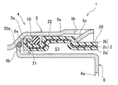
- FIG. 5 is an enlarged view of a portion V in FIG. 4.
- FIG. 6 is an enlarged view of a portion VI in FIG. 4.
- FIG. 1 shows a fuel supply pipe 1 for a vehicle according to an embodiment of the present invention.
- the fuel supply pipe 1 serves as a fuel passage when fuel is supplied to the fuel tank 3 of the vehicle, and includes a cylindrical resin supply pipe main body 2 having one end connected to the fuel tank 3. .
- the fuel supply pipe main body 2 is a blow-molded body manufactured by blow molding. As shown in FIGS. 5 and 6, an ethylene-vinyl alcohol having fuel permeation resistance is provided in a middle part of the fuel supply pipe main body 2 in the thickness direction.
- a resin barrier layer 2c made of a copolymer (EVOH) is provided continuously from the peripheral edge of one opening of the oil supply pipe main body 2 to the peripheral edge of the other opening.
- FIG. 4 does not show the resin barrier layer 2c for convenience.
- a main body inner resin layer 2a made of high-density polyethylene is laminated via an adhesive resin layer (not shown).
- the main body inner resin layer 2a is conductive and has low-temperature impact resistance. are doing.
- a main body outer resin layer 2b made of high-density polyethylene is laminated via an adhesive resin layer (not shown).
- the main body outer resin layer 2b is non-conductive and resistant to low-temperature shock. Have the property.
- an expanded pipe section 20 having a diameter larger than a portion extending from one end of the oil supply pipe main body 2 to a middle part is formed.
- the other end opening of the fuel supply pipe main body 2 will be referred to as an expanded pipe opening 20a.
- An annular groove 21 extending annularly around the cylinder center line C1 is formed on the outer peripheral surface of the expanding portion 20 near the expanding opening 20a.
- annular projecting portion 22 projecting outward is formed in a portion of the tubular expanding portion 20 that is continuous with the annular concave groove 21 farther from the tubular opening 20a.
- a projecting tube portion 23 is formed which protrudes outward in a substantially disk shape. As shown in FIG. 6, a mounting hole 23a penetrating in the protruding direction and communicating the inside and outside of the oil supply pipe main body 2 is formed.
- the protruding cylindrical portion 23 forms an inner peripheral surface of the protruding cylindrical portion 23, and includes a conductive in-cylinder resin layer 23b.
- the in-cylinder resin layer 23b is continuous with the main body inner resin layer 2a. I have.
- a fitting projection 24 having a substantially rectangular parallelepiped shape is protrudingly provided near the projecting cylindrical portion 23 on the outer peripheral surface of the expanded tube portion 20, as shown in FIG.
- the fuel supply pipe 1 includes a short, substantially cylindrical nozzle guide 4, and one end of the nozzle guide 4 is assembled to the expanded pipe opening 20 a of the fuel supply pipe main body 2.
- a refueling cap 11 is detachably attached to the other end opening of the nozzle guide 4, and the nozzle guide 4 connects the nozzle G1 of the refueling gun G with the refueling cap 11 removed as shown in FIG. It is designed to be guided inside the oil supply pipe main body 2.
- the nozzle guide 4 is a metal body obtained by press-forming an iron plate, and includes a first cylindrical body 5 that forms an outer peripheral surface of the nozzle guide 4 and the first cylindrical body.
- a second cylindrical body 6 (nozzle insertion portion) disposed inside one end side of the body 5, wherein the cylindrical center lines of the first cylindrical body 5 and the second cylindrical body 6 coincide with the cylindrical center line C 1. I do.
- annular restricting portion 5 e In the middle part of the first cylindrical body 5, there is provided an annular restricting portion 5 e whose diameter gradually decreases from one end side to the other end side of the first cylindrical body 5. Is larger than the outer diameter of the other half.
- the annular restricting portion 5e is configured to insert the other end of the oil supply pipe main body 2 into the first cylindrical body 5 from one end side of the first cylindrical body 5 to insert the first cylindrical body 5 ( The movement of the nozzle guide 4) toward the other end opening side is regulated.
- a plurality of first cutouts 5b cut out in a substantially U-shape in a side view are formed around the center line C1 of the annular cover 5a at positions near the periphery of the opening.
- each of the first cutouts 5b has a protruding portion 5c (an engaging portion) that protrudes obliquely away from the peripheral edge of the opening of the annular cover portion 5a and toward the inside of the annular cover portion 5a. Joint) is provided.
- the protruding portion 5c is a portion that protrudes inward from a cutout portion formed by cutting out the annular cover portion 5a in a U-shape, and the other end side of the oil supply pipe main body 2 is formed of the annular cover portion 5a. It is formed by bending inward of the annular cover portion 5a in a state where it is inserted inward and regulated by the annular regulating portion 5e.
- each of the protrusions 5 c is engaged with a side of the annular overhanging part 22 far from the expansion pipe opening 20 a, and 4 is prevented from coming off from the oil supply pipe main body 2.
- the annular cover portion 5a is formed with a cutout recess 5d which is open to the periphery of the opening of the annular cover portion 5a.
- An annular folded portion 5f that is folded outward in the radial direction is formed in the peripheral portion of the opening at the other end of the first cylindrical body 5, and at the position near the folded portion 5f on the other end side of the first cylindrical body 5, a single thread is formed. 5g is formed.
- a nozzle insertion port 6a corresponding to the outer diameter of the nozzle G1 of the refueling gun G is formed at one end of the second cylindrical body 6, and the nozzle insertion port 6a is connected to the nozzle guide 4.
- the inserted nozzle G1 is guided to the inside of the oil supply pipe main body 2.
- a flange portion 6b extending outward is provided on the periphery of the other end opening of the second cylindrical body 6.
- the second cylindrical body 6 forms an annular welded portion 6e by laser welding between the outer peripheral edge of the flange portion 6b and the inner peripheral surface of the annular regulating portion 5e of the first cylindrical body 5.
- an annular space S1 extending around the cylinder center line C1 where the other end of the oil supply pipe main body 2 is located is provided between the second cylindrical body 6 and the annular cover portion 5a. Is formed.
- the second cylindrical body 6 is disposed inside the other end side of the oil supply pipe main body 2, and one end opening periphery is separated from the one end opening periphery of the first cylinder 5, while the other end opening periphery is the first cylinder.
- the body 5 is connected to the inner peripheral surface of the middle part.
- a second cutout portion 6c cut out in a substantially U-shape in a side view is formed at a position near the flange portion 6b of the second cylindrical body 6, as shown in FIG.
- the second cutout 6c is provided with a grounding portion 6d that extends obliquely so as to approach the flange portion 6b and toward the other end of the oil supply pipe main body 2.
- the tip of the ground portion 6 d is in contact with the inner peripheral surface on the other end side of the oil supply pipe main body 2, and supplies the static electricity charged to the oil supply worker when the oil supply worker puts his hand on the oil supply cap 11. It escapes to the tube main body 2 side.
- the annular seal member 10 is fitted in the annular concave groove 21 of the oil supply pipe main body 2.
- the seal member 10 is a rubber body made of fluorine rubber having fuel permeation resistance. As shown in FIG. 5, a gap between the inner peripheral surface of the annular concave groove 21 and the inner peripheral surface of the annular cover portion 5a is provided. Sealed.
- a breather tube 7 having one end connected to the fuel tank 3 and the other end connected to the expanded portion 20 of the oil supply pipe main body 2 is provided sideways on the side of the oil supply pipe main body 2.
- the breather tube 7 discharges air containing vaporized fuel from the fuel tank 3 toward the nozzle guide 4 of the fuel supply pipe main body 2.
- the breather tube 7 has an elongated cylindrical resin body 8 having one end connected to the fuel tank 3, and is connected to the other end of the tube body 8, and connects the tube body 8 to the oil supply pipe body 2. And a resin-made joint member 9.
- the tube main body 8 is formed by one-color molding, and includes a tube main body layer 8a having conductivity.
- the joint member 9 is formed by two-color molding and has a conductive outer joint layer 91 forming the outer peripheral surface of the joint member 9 and a non-conductive inner joint layer 92 forming the inner peripheral surface of the joint member 9. It has.
- the joint member 9 has a substantially L-shape in a side view, and includes a first joint 9 a extending along the oil supply pipe main body 2, and lubrication from the first joint 9 a. And a second joint portion 9b extending toward the pipe main body 2.
- the first joint portion 9a has a bamboo-shaped connection surface portion 9c in which a plurality of annularly extending ridges are juxtaposed.
- the O-ring 12 is externally fitted to the connection surface portion 9c, and the first joint portion 9a is connected to a tube.
- the tube main body layer 8a and the joint outer layer 91 form the tube conductive resin layer 13 of the present invention.
- the tube conductive resin layer 13 forms the outer peripheral surface of the breather tube 7.
- An annular ridge 9d projecting outward is formed in the middle of the second joint 9b.
- the second joint 9b is press-fitted into the mounting hole 23a of the oil supply pipe main body 2, and the annular ridge 9d is formed.
- the joint member 9 and the oil supply pipe main body 2 are connected by connecting the protruding tubular portion 23 with the welding portion W1, so that the tube conductive resin layer 13 and the in-cylinder resin layer 23b are continuous.
- the oil supply pipe main body 2 and the breather tube 7 are fixed to a vehicle body (not shown) by a substantially belt-shaped mounting bracket 14 (fixing tool) obtained by press-forming a metal plate. It has become.
- a first curved surface portion 14a corresponding to the outer peripheral surface of the oil supply pipe main body 2 and a second curved surface portion 14b corresponding to the outer peripheral surface of the breather tube 7 are formed on the mounting bracket 14, and the first curved surface portion 14a and the second curved surface are formed.
- the mounting bracket 14 comes into contact with the oil supply pipe main body 2 and the breather tube 7 in a wide range by the surface portion 14b.
- the rubber seal member 10 relatively softer than the resin material is used. Since the oil supply pipe main body 2 and the nozzle guide 4 are assembled so as to fill the gap between the outer peripheral surface of the oil supply pipe main body 2 and the inner peripheral surface of the nozzle guide 4 with small variation in surface roughness, the height is high.
- An airtight fuel supply pipe 1 can be provided.
- the resin barrier layer 2c that does not allow fuel to pass through is provided in the intermediate layer extending from the peripheral edge of one end opening to the peripheral edge of the other end opening of the fuel supply pipe main body 2, the outer peripheral surface of the nozzle guide 4 and the inner peripheral surface of the fuel supply pipe main body 2 are provided.
- the seal member 10 is interposed between the inner peripheral surface of the nozzle guide 4 and the outer peripheral surface of the oil supply pipe main body 2 as compared with the case where the seal member 10 is interposed between It is difficult for the fuel located inside the fuel supply pipe main body 2 to reach the seal member 10 by the amount of moving around the peripheral edge of the end opening (see the arrow X1 in FIG. 5 showing the fuel movement path). Therefore, the amount of fuel permeating outside the fuel supply pipe 1 through the layer interposed between the resin barrier layer 2c and the seal member 10 in the fuel supply pipe main body 2 can be greatly reduced.
- the second cylindrical body 6 is located inside the other end side of the oil supply pipe main body 2 and the peripheral edge of the other end side opening of the second cylindrical body 6 is connected to the inner peripheral surface of the middle part of the first cylindrical body 5.
- the nozzle G1 of the refueling gun G is inserted into the nozzle guide 4
- the nozzle G1 is smoothly guided by the second cylindrical body 6 into the refueling pipe main body 2 without contacting the peripheral edge of the other end opening of the refueling pipe main body 2. Will be done. Therefore, it is possible to provide the fuel supply pipe 1 which is easy to refuel while improving the airtightness between the nozzle guide 4 and the supply pipe main body 2.
- the nozzle guide 4 when assembling the nozzle guide 4 to the fuel supply pipe main body 2, the nozzle guide 4 can be prevented from being detached from the fuel supply pipe main body 2 without performing the press-fitting operation as in Patent Document 1, and the assembly work of the fuel supply pipe 1 is performed. Is easy.
- the annular restricting portion 5 e of the nozzle guide 4 comes into contact with the peripheral edge of the other end opening of the oil supply pipe main body 2, while the nozzle guide 4 is connected to the oil supply pipe 2. Even if it attempts to move in the direction away from the main body 2, the protruding portion 5 c of the nozzle guide 4 comes into contact with the annular projecting portion 22 of the oil supply pipe main body 2. In this manner, the position of the nozzle guide 4 in the direction of the cylinder center line C1 with respect to the oil supply pipe main body 2 is accurately determined, so that the nozzle guide 4 can be assembled at an accurate position with respect to the oil supply pipe main body 2.
- the nozzle guide 4 can be assembled into the oil supply pipe main body 2 without press fitting. it can.
- the other end of the fuel supply pipe main body 2 is connected to one end opening of the nozzle guide 4 before the protrusion 5 c is bent toward the inside of the annular cover 5 a.
- the fuel supply pipe main body 2 can be easily inserted inside the nozzle guide 4.
- the peripheral edge of the other end opening of the oil supply pipe main body 2 comes into contact with the annular restricting portion 5 e of the nozzle guide 4. Can be determined exactly.
- the projecting portion 5c is bent inward of the annular cover portion 5a so that the nozzle guide 4 does not come off from the oil supply pipe main body 2. Can be. In this manner, the nozzle guide 4 can be easily assembled at an accurate position of the oil supply pipe main body 2.
- the tube conductive material forming the outer peripheral surface of the breather tube 7 is formed on the resin inner layer 2a of the oil supply pipe main body 2 facing the opening periphery of the mounting hole 23a.
- the resin layer 13 comes into contact. Therefore, the inner peripheral surface of the oil supply pipe main body 2 is grounded to the vehicle body via the main body inner resin layer 2a, the tube conductive resin layer 13, and the mounting bracket 14, so that ignition due to charging can be prevented.
- the fuel supply pipe main body 2 and the breather tube 7 are formed of a resin material, the weight of the fuel supply pipe 1 can be reduced as a whole.
- the nozzle guide 4 is a metal body formed of an iron plate, but may be formed of a metal material such as a stainless steel material.
- the joint member 9 of the breather tube 7 has a two-layer structure by two-color molding.
- the present invention is not limited to this.
- the outermost layer has conductivity. It may have a structure of three or more layers, or may have a single-layer structure having conductivity.
- the tube body 8 has a structure formed by one-color molding, but may have a structure including two or more layers as long as the outermost layer has conductivity.
- the nozzle guide 4 is formed from a metal material, but may be formed from a resin material.
- the annular restricting portion 5e that determines the position of the oil supply pipe main body 2 with respect to the nozzle guide 4 is formed in an annular shape. Any shape may be used as long as the peripheral edge can contact.
- the annular projecting portion 22 of the oil supply pipe main body 2 is formed in an annular shape.
- the present invention is suitable for a fuel supply pipe serving as a passage when fuel such as gasoline is supplied to a fuel tank of a vehicle.
Landscapes
- Engineering & Computer Science (AREA)
- Chemical & Material Sciences (AREA)
- Combustion & Propulsion (AREA)
- Mechanical Engineering (AREA)
- Life Sciences & Earth Sciences (AREA)
- Sustainable Development (AREA)
- Sustainable Energy (AREA)
- Transportation (AREA)
- General Engineering & Computer Science (AREA)
- Cooling, Air Intake And Gas Exhaust, And Fuel Tank Arrangements In Propulsion Units (AREA)
Abstract
L'invention concerne un corps de tuyau d'alimentation en carburant cylindrique circulaire (2) qui est un corps moulé par soufflage et a une extrémité reliée à un réservoir de carburant (3). Une rainure annulaire (21) s'étendant de manière annulaire autour d'une ligne centrale de cylindre (C1) est formée dans la surface périphérique externe côté autre extrémité du corps de tuyau d'alimentation en carburant (2). Un guide de buse (4) est monté sur l'ouverture d'autre d'extrémité dans le corps de tuyau d'alimentation en carburant (2). Une section couvercle annulaire (5a) pour recouvrir de façon annulaire la surface périphérique externe côté autre extrémité du corps de tuyau d'alimentation en carburant (2) est disposée sur un côté d'extrémité du guide de buse (4). La rainure annulaire (21) comporte un élément d'étanchéité en caoutchouc annulaire (10) pour assurer l'étanchéité entre la surface périphérique interne de la rainure annulaire (21) et la surface périphérique interne de la section couvercle annulaire (5a).
Priority Applications (2)
| Application Number | Priority Date | Filing Date | Title |
|---|---|---|---|
| US17/130,677 US11338668B2 (en) | 2018-06-27 | 2020-12-22 | Fuel filler pipe |
| US17/693,572 US11548378B2 (en) | 2018-06-27 | 2022-03-14 | Fuel filler pipe |
Applications Claiming Priority (6)
| Application Number | Priority Date | Filing Date | Title |
|---|---|---|---|
| JP2018121832A JP7169629B2 (ja) | 2018-06-27 | 2018-06-27 | 燃料給油管 |
| JP2018-121811 | 2018-06-27 | ||
| JP2018121811A JP7370035B2 (ja) | 2018-06-27 | 2018-06-27 | 燃料給油管 |
| JP2018121791A JP2020001517A (ja) | 2018-06-27 | 2018-06-27 | 燃料給油管 |
| JP2018-121791 | 2018-06-27 | ||
| JP2018-121832 | 2018-06-27 |
Related Child Applications (1)
| Application Number | Title | Priority Date | Filing Date |
|---|---|---|---|
| US17/130,677 Continuation US11338668B2 (en) | 2018-06-27 | 2020-12-22 | Fuel filler pipe |
Publications (1)
| Publication Number | Publication Date |
|---|---|
| WO2020003702A1 true WO2020003702A1 (fr) | 2020-01-02 |
Family
ID=68987029
Family Applications (1)
| Application Number | Title | Priority Date | Filing Date |
|---|---|---|---|
| PCT/JP2019/016559 Ceased WO2020003702A1 (fr) | 2018-06-27 | 2019-04-18 | Tuyau d'alimentation en carburant |
Country Status (2)
| Country | Link |
|---|---|
| US (2) | US11338668B2 (fr) |
| WO (1) | WO2020003702A1 (fr) |
Cited By (3)
| Publication number | Priority date | Publication date | Assignee | Title |
|---|---|---|---|---|
| US20210188082A1 (en) * | 2019-12-23 | 2021-06-24 | Sumitomo Riko Company Limited | Resin filler tube and manufacturing method for the same |
| WO2021263002A1 (fr) * | 2020-06-24 | 2021-12-30 | Stant Usa Corp. | Ensemble de remplissage de réservoir de carburant |
| WO2022181089A1 (fr) * | 2021-02-24 | 2022-09-01 | 八千代工業株式会社 | Structure de mise à la terre pour tube de remplissage |
Families Citing this family (1)
| Publication number | Priority date | Publication date | Assignee | Title |
|---|---|---|---|---|
| WO2020003702A1 (fr) * | 2018-06-27 | 2020-01-02 | 株式会社キーレックス | Tuyau d'alimentation en carburant |
Citations (5)
| Publication number | Priority date | Publication date | Assignee | Title |
|---|---|---|---|---|
| JP2005199757A (ja) * | 2004-01-13 | 2005-07-28 | Toyoda Gosei Co Ltd | フィラーパイプ |
| JP2009220590A (ja) * | 2008-03-13 | 2009-10-01 | Toyoda Gosei Co Ltd | 燃料給油装置とアース線接続構造 |
| JP2011511906A (ja) * | 2007-11-20 | 2011-04-14 | イートン コーポレーション | コンポーネントを密閉するためのアセンブリ及び方法 |
| JP2013023168A (ja) * | 2011-07-26 | 2013-02-04 | Toyoda Gosei Co Ltd | 燃料給油装置 |
| JP2015157494A (ja) * | 2014-02-21 | 2015-09-03 | 豊田合成株式会社 | 燃料供給装置 |
Family Cites Families (13)
| Publication number | Priority date | Publication date | Assignee | Title |
|---|---|---|---|---|
| JP2000085381A (ja) | 1998-09-16 | 2000-03-28 | Yachiyo Industry Co Ltd | 燃料タンク用給油管 |
| DE112013001045T5 (de) * | 2012-02-20 | 2014-12-04 | Honda Motor Co., Ltd. | Struktur für einen Einfüllabschnitt von einem Kraftstoffeinfüllrohr |
| JP5880374B2 (ja) * | 2012-09-24 | 2016-03-09 | 豊田合成株式会社 | フィラーネック |
| JP6070440B2 (ja) * | 2013-02-15 | 2017-02-01 | 豊田合成株式会社 | 給油装置 |
| JP6160871B2 (ja) * | 2014-03-27 | 2017-07-12 | 豊田合成株式会社 | 車両用給油装置 |
| JP6303926B2 (ja) * | 2014-08-29 | 2018-04-04 | 豊田合成株式会社 | 給油装置 |
| JP6510839B2 (ja) * | 2015-03-16 | 2019-05-08 | 住友理工株式会社 | 樹脂製給油口 |
| US9855840B2 (en) * | 2015-06-11 | 2018-01-02 | Toyoda Gosei Co., Ltd. | Fuel supply apparatus |
| JP6561893B2 (ja) * | 2016-04-01 | 2019-08-21 | 豊田合成株式会社 | 燃料供給装置 |
| JP6693019B2 (ja) * | 2016-10-14 | 2020-05-13 | 豊田合成株式会社 | 給油装置 |
| JP6522573B2 (ja) * | 2016-11-07 | 2019-05-29 | 豊田合成株式会社 | 燃料供給装置 |
| WO2018160698A1 (fr) * | 2017-03-01 | 2018-09-07 | Stant Usa Corp. | Ensemble tuyau de remplissage de réservoir de carburant |
| WO2020003702A1 (fr) * | 2018-06-27 | 2020-01-02 | 株式会社キーレックス | Tuyau d'alimentation en carburant |
-
2019
- 2019-04-18 WO PCT/JP2019/016559 patent/WO2020003702A1/fr not_active Ceased
-
2020
- 2020-12-22 US US17/130,677 patent/US11338668B2/en active Active
-
2022
- 2022-03-14 US US17/693,572 patent/US11548378B2/en active Active
Patent Citations (5)
| Publication number | Priority date | Publication date | Assignee | Title |
|---|---|---|---|---|
| JP2005199757A (ja) * | 2004-01-13 | 2005-07-28 | Toyoda Gosei Co Ltd | フィラーパイプ |
| JP2011511906A (ja) * | 2007-11-20 | 2011-04-14 | イートン コーポレーション | コンポーネントを密閉するためのアセンブリ及び方法 |
| JP2009220590A (ja) * | 2008-03-13 | 2009-10-01 | Toyoda Gosei Co Ltd | 燃料給油装置とアース線接続構造 |
| JP2013023168A (ja) * | 2011-07-26 | 2013-02-04 | Toyoda Gosei Co Ltd | 燃料給油装置 |
| JP2015157494A (ja) * | 2014-02-21 | 2015-09-03 | 豊田合成株式会社 | 燃料供給装置 |
Cited By (8)
| Publication number | Priority date | Publication date | Assignee | Title |
|---|---|---|---|---|
| US20210188082A1 (en) * | 2019-12-23 | 2021-06-24 | Sumitomo Riko Company Limited | Resin filler tube and manufacturing method for the same |
| US11919384B2 (en) * | 2019-12-23 | 2024-03-05 | Sumitomo Riko Company Limited | Resin filler tube and manufacturing method for the same |
| WO2021263002A1 (fr) * | 2020-06-24 | 2021-12-30 | Stant Usa Corp. | Ensemble de remplissage de réservoir de carburant |
| WO2022181089A1 (fr) * | 2021-02-24 | 2022-09-01 | 八千代工業株式会社 | Structure de mise à la terre pour tube de remplissage |
| JPWO2022181089A1 (fr) * | 2021-02-24 | 2022-09-01 | ||
| CN116723952A (zh) * | 2021-02-24 | 2023-09-08 | 八千代工业株式会社 | 加注管的接地构造 |
| CN116723952B (zh) * | 2021-02-24 | 2024-04-12 | 八千代工业株式会社 | 加注管的接地构造 |
| JP7607394B2 (ja) | 2021-02-24 | 2024-12-27 | マザーサンヤチヨ・オートモーティブシステムズ株式会社 | フィラーパイプのアース構造 |
Also Published As
| Publication number | Publication date |
|---|---|
| US20210107353A1 (en) | 2021-04-15 |
| US11338668B2 (en) | 2022-05-24 |
| US20220219527A1 (en) | 2022-07-14 |
| US11548378B2 (en) | 2023-01-10 |
Similar Documents
| Publication | Publication Date | Title |
|---|---|---|
| WO2020003702A1 (fr) | Tuyau d'alimentation en carburant | |
| US20090107583A1 (en) | Fill Nozzle Positioning Apparatus | |
| JP2002039028A (ja) | フランジシールアセンブリ | |
| JP6156184B2 (ja) | 燃料供給装置 | |
| US20150151633A1 (en) | Fueling device and manufacturing method of fueling device | |
| CN105228846A (zh) | 注油管的安装方法以及注油管的安装结构 | |
| JP6693019B2 (ja) | 給油装置 | |
| JP2020001517A (ja) | 燃料給油管 | |
| CN104512242B (zh) | 燃料供油装置 | |
| US20180209589A1 (en) | High-pressure container | |
| JP6522573B2 (ja) | 燃料供給装置 | |
| JP7370035B2 (ja) | 燃料給油管 | |
| JP7169629B2 (ja) | 燃料給油管 | |
| US20210260991A1 (en) | Refueling port | |
| US10953742B2 (en) | Fuel tank | |
| JP7226373B2 (ja) | 接続構造体 | |
| JP4884156B2 (ja) | 燃料タンクの給油口構造 | |
| JP6087590B2 (ja) | 燃料給油管 | |
| US10815957B2 (en) | Ignition coil unit and ignition system, capable of suppressing deformation of the seal section, used in internal combustion engine | |
| JP7134471B2 (ja) | 車両用燃料給油管 | |
| JP6452647B2 (ja) | 燃料系部品 | |
| JP7291650B2 (ja) | 給油口 | |
| JP2006198810A (ja) | 合成樹脂製液体タンクの製造方法及び合成樹脂製液体タンク | |
| GB2514482A (en) | Conductive connector insert for fluidically connecting fuel-conveying ducts to one another | |
| JP4160885B2 (ja) | 樹脂製燃料タンクにおける逆流防止バルブの取り付け構造 |
Legal Events
| Date | Code | Title | Description |
|---|---|---|---|
| 121 | Ep: the epo has been informed by wipo that ep was designated in this application |
Ref document number: 19825354 Country of ref document: EP Kind code of ref document: A1 |
|
| NENP | Non-entry into the national phase |
Ref country code: DE |
|
| 122 | Ep: pct application non-entry in european phase |
Ref document number: 19825354 Country of ref document: EP Kind code of ref document: A1 |