WO2020003702A1 - 燃料給油管 - Google Patents
燃料給油管 Download PDFInfo
- Publication number
- WO2020003702A1 WO2020003702A1 PCT/JP2019/016559 JP2019016559W WO2020003702A1 WO 2020003702 A1 WO2020003702 A1 WO 2020003702A1 JP 2019016559 W JP2019016559 W JP 2019016559W WO 2020003702 A1 WO2020003702 A1 WO 2020003702A1
- Authority
- WO
- WIPO (PCT)
- Prior art keywords
- main body
- supply pipe
- oil supply
- pipe main
- fuel
- Prior art date
- Legal status (The legal status is an assumption and is not a legal conclusion. Google has not performed a legal analysis and makes no representation as to the accuracy of the status listed.)
- Ceased
Links
Images



Classifications
-
- B—PERFORMING OPERATIONS; TRANSPORTING
- B60—VEHICLES IN GENERAL
- B60K—ARRANGEMENT OR MOUNTING OF PROPULSION UNITS OR OF TRANSMISSIONS IN VEHICLES; ARRANGEMENT OR MOUNTING OF PLURAL DIVERSE PRIME-MOVERS IN VEHICLES; AUXILIARY DRIVES FOR VEHICLES; INSTRUMENTATION OR DASHBOARDS FOR VEHICLES; ARRANGEMENTS IN CONNECTION WITH COOLING, AIR INTAKE, GAS EXHAUST OR FUEL SUPPLY OF PROPULSION UNITS IN VEHICLES
- B60K15/00—Arrangement in connection with fuel supply of combustion engines or other fuel consuming energy converters, e.g. fuel cells; Mounting or construction of fuel tanks
- B60K15/03—Fuel tanks
- B60K15/04—Tank inlets
-
- B—PERFORMING OPERATIONS; TRANSPORTING
- B60—VEHICLES IN GENERAL
- B60K—ARRANGEMENT OR MOUNTING OF PROPULSION UNITS OR OF TRANSMISSIONS IN VEHICLES; ARRANGEMENT OR MOUNTING OF PLURAL DIVERSE PRIME-MOVERS IN VEHICLES; AUXILIARY DRIVES FOR VEHICLES; INSTRUMENTATION OR DASHBOARDS FOR VEHICLES; ARRANGEMENTS IN CONNECTION WITH COOLING, AIR INTAKE, GAS EXHAUST OR FUEL SUPPLY OF PROPULSION UNITS IN VEHICLES
- B60K15/00—Arrangement in connection with fuel supply of combustion engines or other fuel consuming energy converters, e.g. fuel cells; Mounting or construction of fuel tanks
- B60K15/03—Fuel tanks
- B60K15/04—Tank inlets
- B60K15/0406—Filler caps for fuel tanks
-
- F—MECHANICAL ENGINEERING; LIGHTING; HEATING; WEAPONS; BLASTING
- F02—COMBUSTION ENGINES; HOT-GAS OR COMBUSTION-PRODUCT ENGINE PLANTS
- F02M—SUPPLYING COMBUSTION ENGINES IN GENERAL WITH COMBUSTIBLE MIXTURES OR CONSTITUENTS THEREOF
- F02M37/00—Apparatus or systems for feeding liquid fuel from storage containers to carburettors or fuel-injection apparatus; Arrangements for purifying liquid fuel specially adapted for, or arranged on, internal-combustion engines
-
- B—PERFORMING OPERATIONS; TRANSPORTING
- B60—VEHICLES IN GENERAL
- B60K—ARRANGEMENT OR MOUNTING OF PROPULSION UNITS OR OF TRANSMISSIONS IN VEHICLES; ARRANGEMENT OR MOUNTING OF PLURAL DIVERSE PRIME-MOVERS IN VEHICLES; AUXILIARY DRIVES FOR VEHICLES; INSTRUMENTATION OR DASHBOARDS FOR VEHICLES; ARRANGEMENTS IN CONNECTION WITH COOLING, AIR INTAKE, GAS EXHAUST OR FUEL SUPPLY OF PROPULSION UNITS IN VEHICLES
- B60K15/00—Arrangement in connection with fuel supply of combustion engines or other fuel consuming energy converters, e.g. fuel cells; Mounting or construction of fuel tanks
- B60K15/03—Fuel tanks
- B60K2015/03328—Arrangements or special measures related to fuel tanks or fuel handling
- B60K2015/03447—Arrangements or special measures related to fuel tanks or fuel handling for improving the sealing
-
- B—PERFORMING OPERATIONS; TRANSPORTING
- B60—VEHICLES IN GENERAL
- B60K—ARRANGEMENT OR MOUNTING OF PROPULSION UNITS OR OF TRANSMISSIONS IN VEHICLES; ARRANGEMENT OR MOUNTING OF PLURAL DIVERSE PRIME-MOVERS IN VEHICLES; AUXILIARY DRIVES FOR VEHICLES; INSTRUMENTATION OR DASHBOARDS FOR VEHICLES; ARRANGEMENTS IN CONNECTION WITH COOLING, AIR INTAKE, GAS EXHAUST OR FUEL SUPPLY OF PROPULSION UNITS IN VEHICLES
- B60K15/00—Arrangement in connection with fuel supply of combustion engines or other fuel consuming energy converters, e.g. fuel cells; Mounting or construction of fuel tanks
- B60K15/03—Fuel tanks
- B60K2015/03328—Arrangements or special measures related to fuel tanks or fuel handling
- B60K2015/03453—Arrangements or special measures related to fuel tanks or fuel handling for fixing or mounting parts of the fuel tank together
-
- B—PERFORMING OPERATIONS; TRANSPORTING
- B60—VEHICLES IN GENERAL
- B60K—ARRANGEMENT OR MOUNTING OF PROPULSION UNITS OR OF TRANSMISSIONS IN VEHICLES; ARRANGEMENT OR MOUNTING OF PLURAL DIVERSE PRIME-MOVERS IN VEHICLES; AUXILIARY DRIVES FOR VEHICLES; INSTRUMENTATION OR DASHBOARDS FOR VEHICLES; ARRANGEMENTS IN CONNECTION WITH COOLING, AIR INTAKE, GAS EXHAUST OR FUEL SUPPLY OF PROPULSION UNITS IN VEHICLES
- B60K15/00—Arrangement in connection with fuel supply of combustion engines or other fuel consuming energy converters, e.g. fuel cells; Mounting or construction of fuel tanks
- B60K15/03—Fuel tanks
- B60K15/035—Fuel tanks characterised by venting means
- B60K2015/03523—Arrangements of the venting tube
- B60K2015/03538—Arrangements of the venting tube the venting tube being connected with the filler tube
-
- B—PERFORMING OPERATIONS; TRANSPORTING
- B60—VEHICLES IN GENERAL
- B60K—ARRANGEMENT OR MOUNTING OF PROPULSION UNITS OR OF TRANSMISSIONS IN VEHICLES; ARRANGEMENT OR MOUNTING OF PLURAL DIVERSE PRIME-MOVERS IN VEHICLES; AUXILIARY DRIVES FOR VEHICLES; INSTRUMENTATION OR DASHBOARDS FOR VEHICLES; ARRANGEMENTS IN CONNECTION WITH COOLING, AIR INTAKE, GAS EXHAUST OR FUEL SUPPLY OF PROPULSION UNITS IN VEHICLES
- B60K15/00—Arrangement in connection with fuel supply of combustion engines or other fuel consuming energy converters, e.g. fuel cells; Mounting or construction of fuel tanks
- B60K15/03—Fuel tanks
- B60K15/04—Tank inlets
- B60K15/0406—Filler caps for fuel tanks
- B60K2015/0419—Self-sealing closure caps, e.g. that don't have to be removed manually
-
- B—PERFORMING OPERATIONS; TRANSPORTING
- B60—VEHICLES IN GENERAL
- B60K—ARRANGEMENT OR MOUNTING OF PROPULSION UNITS OR OF TRANSMISSIONS IN VEHICLES; ARRANGEMENT OR MOUNTING OF PLURAL DIVERSE PRIME-MOVERS IN VEHICLES; AUXILIARY DRIVES FOR VEHICLES; INSTRUMENTATION OR DASHBOARDS FOR VEHICLES; ARRANGEMENTS IN CONNECTION WITH COOLING, AIR INTAKE, GAS EXHAUST OR FUEL SUPPLY OF PROPULSION UNITS IN VEHICLES
- B60K15/00—Arrangement in connection with fuel supply of combustion engines or other fuel consuming energy converters, e.g. fuel cells; Mounting or construction of fuel tanks
- B60K15/03—Fuel tanks
- B60K15/04—Tank inlets
- B60K2015/0458—Details of the tank inlet
- B60K2015/047—Manufacturing of the fuel inlet or connecting elements to fuel inlet, e.g. pipes or venting tubes
-
- B—PERFORMING OPERATIONS; TRANSPORTING
- B60—VEHICLES IN GENERAL
- B60K—ARRANGEMENT OR MOUNTING OF PROPULSION UNITS OR OF TRANSMISSIONS IN VEHICLES; ARRANGEMENT OR MOUNTING OF PLURAL DIVERSE PRIME-MOVERS IN VEHICLES; AUXILIARY DRIVES FOR VEHICLES; INSTRUMENTATION OR DASHBOARDS FOR VEHICLES; ARRANGEMENTS IN CONNECTION WITH COOLING, AIR INTAKE, GAS EXHAUST OR FUEL SUPPLY OF PROPULSION UNITS IN VEHICLES
- B60K15/00—Arrangement in connection with fuel supply of combustion engines or other fuel consuming energy converters, e.g. fuel cells; Mounting or construction of fuel tanks
- B60K15/03—Fuel tanks
- B60K15/04—Tank inlets
- B60K2015/0458—Details of the tank inlet
- B60K2015/0477—Details of the filler neck tank side
Definitions
- the present invention relates to a fuel supply pipe that serves as a passage when fuel such as gasoline is supplied to a fuel tank of a vehicle.
- a fuel filler pipe disclosed in Patent Document 1 includes a cylindrical filler pipe body formed of a resin material having one end connected to a fuel tank.
- a cylindrical nozzle guide for guiding the nozzle of the gun to the inside of the oil supply pipe main body is assembled by press fitting.
- the present invention has been made in view of such a point, and an object of the present invention is to provide a fuel supply pipe having high airtightness even when a main body part is made of a resin body manufactured by blow molding. To provide.
- the present invention is characterized in that the nozzle guide is assembled to the oil supply pipe main body so as to cover a part of the outer peripheral surface of the oil supply pipe main body.
- a cylindrical resin-made oil supply pipe main body having one end connected to the fuel tank, and one end side is assembled to the other end opening of the oil supply pipe main body, and an oil supply cap is detachably attached to the other end opening.
- the fuel supply pipe provided with a cylindrical nozzle guide for guiding the nozzle of the fuel supply gun to the inside of the fuel supply pipe main body with the fuel supply cap removed, the following solution is taken.
- the oil supply pipe main body is a blow molded body, and an annular concave groove extending annularly around the cylinder center line is formed on the outer peripheral surface on the other end side of the oil supply pipe main body.
- An annular cover portion is provided at one end of the nozzle guide so as to annularly cover the outer peripheral surface at the other end of the oil supply pipe main body.
- the annular concave groove has an inner peripheral surface of the annular concave groove and the annular cover.
- An annular rubber seal member for sealing between the inner peripheral surface of the portion and the inner peripheral surface is fitted.
- a resin barrier layer having fuel resistance is provided continuously from the peripheral edge at one end to the peripheral edge at the other end at a middle part in the thickness direction of the fuel filler pipe.
- the nozzle guide is a metal body
- the sealing member is a fuel-resistant rubber body.
- the nozzle guide includes a first cylindrical body having the annular cover portion at one end opening side, an inner side of the first cylindrical body at one end side, and The oil supply pipe is disposed inside the other end of the oil supply pipe, and one end of the opening is spaced apart from the one end of the first cylinder, and the other end of the opening is connected to the middle of the first cylinder. And a second cylindrical body.
- the nozzle guide is a metal body, and a projecting portion projecting outward is provided on an outer peripheral surface on the other end side of the oil supply pipe main body.
- the nozzle guide is provided with the other end opening of the nozzle guide in the oil supply pipe main body in a state where the other end opening side of the oil supply pipe main body is inserted into the nozzle guide from one end side of the nozzle guide.
- a restricting portion that restricts movement to the side, an annular cover portion provided at one end of the nozzle guide and annularly covering the outer peripheral surface on the other end opening side of the oil supply pipe body regulated by the restricting portion;
- An engaging portion formed on the cover portion and engaged with a side of the overhang portion farther from a peripheral edge of the other end opening of the oil supply pipe main body is provided.
- the annular cover portion is formed with a cutout recess which is open to the periphery of the opening of the annular cover portion, and the outer peripheral surface on the other end side of the oil supply pipe main body is provided with the annular shape.
- a fitting projection that fits into the notch recess is formed in a state in which the cover covers the outer peripheral surface on the other end opening side of the oil supply pipe main body.
- the restricting portion is provided continuously with the annular cover portion, and is constituted by an annular portion whose diameter gradually decreases as the distance from the annular cover portion increases.
- the joint portion is formed by cutting out the annular cover portion into a U-shape and projecting inward from a cut-out portion formed by a cut-out portion.
- the other end of the oil supply pipe main body is inward of the annular cover portion. And is formed by being bent toward the inside of the annular cover in a state where the annular cover is inserted into the annular cover.
- one end is connected to the fuel tank on one side of the fuel pipe main body, and the other end is the other end of the fuel pipe main body.
- a cylindrical resin breather tube connected to the opening side and having a conductive tube conductive resin layer constituting an outer peripheral surface is provided side by side, and the oil supply pipe main body is a conductive resin forming an inner peripheral surface of the oil supply pipe main body.
- a mounting hole fixed to the vehicle body and having the other end side of the breather tube press-fitted is formed at the other end opening side of the oil supply pipe main body.
- a projecting tubular portion having the mounting hole projecting outward and penetrating in the projecting direction is provided on the other end opening side of the oil supply pipe main body,
- the portion constitutes an inner peripheral surface of the protruding cylindrical portion, and includes an in-cylinder resin layer having conductivity which is continuous with the main body inner resin layer.
- a cylindrical nozzle insertion portion is provided at one end side of the nozzle guide, which is located inside the other end opening side of the oil supply pipe main body.
- the nozzle insertion portion is provided with a ground portion extending outward and having an extended end contacting the inner peripheral surface of the oil supply pipe main body.
- the surface roughness is reduced by using a rubber sealing member that is relatively softer than the resin material. Since the fuel supply pipe main body and the nozzle guide are assembled so that the gap between the outer peripheral face of the fuel pipe main body and the inner peripheral face of the nozzle guide with small variation is filled, a fuel oil pipe having high airtightness can be obtained. it can.
- the barrier layer that does not allow fuel to pass through is provided in the intermediate layer extending from the peripheral edge of one end opening to the peripheral edge of the other end opening of the fuel supply pipe main body, the outer peripheral surface of the nozzle guide and the internal peripheral surface of the fuel supply pipe main body are provided.
- the seal member is interposed between the inner peripheral surface of the nozzle guide and the outer peripheral surface of the oil supply pipe main body, the periphery of the other end opening of the oil supply pipe main body is wrapped around as compared with the case where the seal member is interposed between It is difficult for the fuel located inside the fuel supply pipe main body to reach the seal member by the amount of movement. Therefore, it is possible to greatly reduce the amount of fuel permeating to the outside of the fuel filler pipe via the layer interposed between the barrier layer and the seal member in the fuel filler pipe main body.
- the second cylindrical body is located inside the other end side of the oil supply pipe main body, and the peripheral edge of the opening at the other end side of the second cylindrical body is connected to the inner peripheral surface of the middle part of the first cylindrical body.
- the fourth invention when assembling the nozzle guide to the fuel supply pipe main body, it is possible to prevent the nozzle guide from coming off from the fuel supply pipe main body without performing the press-fitting operation as in Patent Literature 1. Easy. Further, when the nozzle guide tries to move toward one end side of the oil supply pipe main body, the restricting portion of the nozzle guide comes into contact with the peripheral edge of the other end opening of the oil supply pipe main body, while the nozzle guide moves in the direction to come off from the oil supply pipe main body. Also, the engaging portion of the nozzle guide comes into contact with the projecting portion of the oil supply pipe main body.
- the position of the nozzle guide in the direction of the center line of the cylinder with respect to the oil supply pipe main body is accurately determined, so that the nozzle guide can be assembled at an accurate position with respect to the oil supply pipe main body. Furthermore, even if the oil supply pipe main body is a resin body and the nozzle guide is a metal body, it is possible to assemble the oil supply pipe main body without pressing the nozzle guide into the oil supply pipe main body by applying the structure of the present invention.
- the fitting projection is caught in the cutout recess. Rotation around the center line can be reliably prevented.
- the other end of the oil supply pipe main body is inserted into one end opening of the nozzle guide before the protrusion is bent toward the inside of the annular cover section. This makes it possible to easily insert the oil supply pipe body inside the nozzle guide.
- the peripheral edge of the other end opening of the oil supply pipe main body comes into contact with the regulating portion of the nozzle guide, so that the insertion position of the oil supply pipe main body with respect to the nozzle guide can be accurately determined.
- the protruding portion is bent inward of the annular cover so that the nozzle guide can be prevented from being detached from the oil supply pipe main body. In this manner, the nozzle guide can be easily assembled at an accurate position of the oil supply pipe main body.
- the tube conductive resin layer forming the outer peripheral surface of the breather tube is formed on the resin layer inside the main body of the oil supply pipe facing the opening periphery of the mounting hole. Will be in contact. Therefore, the inner peripheral surface of the fuel supply pipe main body is grounded to the vehicle body via the main body inner resin layer, the tube conductive resin layer, and the fixture, so that ignition due to charging can be prevented. Further, since the conductive resin layer, which is relatively expensive in manufacturing the fuel supply pipe main body, is provided only on the inner portion of the fuel supply pipe main body, the cost of the completed fuel supply pipe can be prevented from increasing. . Further, since the fuel supply pipe main body and the breather tube are formed of a resin material, the weight of the entire fuel supply pipe can be reduced.
- the contact area of the conductive portion of the oil supply pipe main body side with respect to the outer peripheral surface of the breather tube by the in-cylinder resin layer is changed to the oil supply pipe main body. Is wider than when only the resin layer inside the main body is used. Therefore, even if the oil supply pipe main body is charged, the static electricity can be surely flown to the vehicle body.
- the ninth invention when the refueling worker puts his hand on the refueling cap, even if the refueling worker is charged with static electricity, the static electricity is transferred from the nozzle guide to the vehicle body via the grounding portion connected to the refueling pipe main body. Since it escapes to the side, it is possible to reliably prevent ignition due to charging.
- FIG. 3 is a view taken in the direction of the arrow III in FIG. 1.
- FIG. 4 is a sectional view taken along line IV-IV in FIG. 1.
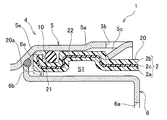
- FIG. 5 is an enlarged view of a portion V in FIG. 4.
- FIG. 6 is an enlarged view of a portion VI in FIG. 4.
- FIG. 1 shows a fuel supply pipe 1 for a vehicle according to an embodiment of the present invention.
- the fuel supply pipe 1 serves as a fuel passage when fuel is supplied to the fuel tank 3 of the vehicle, and includes a cylindrical resin supply pipe main body 2 having one end connected to the fuel tank 3. .
- the fuel supply pipe main body 2 is a blow-molded body manufactured by blow molding. As shown in FIGS. 5 and 6, an ethylene-vinyl alcohol having fuel permeation resistance is provided in a middle part of the fuel supply pipe main body 2 in the thickness direction.
- a resin barrier layer 2c made of a copolymer (EVOH) is provided continuously from the peripheral edge of one opening of the oil supply pipe main body 2 to the peripheral edge of the other opening.
- FIG. 4 does not show the resin barrier layer 2c for convenience.
- a main body inner resin layer 2a made of high-density polyethylene is laminated via an adhesive resin layer (not shown).
- the main body inner resin layer 2a is conductive and has low-temperature impact resistance. are doing.
- a main body outer resin layer 2b made of high-density polyethylene is laminated via an adhesive resin layer (not shown).
- the main body outer resin layer 2b is non-conductive and resistant to low-temperature shock. Have the property.
- an expanded pipe section 20 having a diameter larger than a portion extending from one end of the oil supply pipe main body 2 to a middle part is formed.
- the other end opening of the fuel supply pipe main body 2 will be referred to as an expanded pipe opening 20a.
- An annular groove 21 extending annularly around the cylinder center line C1 is formed on the outer peripheral surface of the expanding portion 20 near the expanding opening 20a.
- annular projecting portion 22 projecting outward is formed in a portion of the tubular expanding portion 20 that is continuous with the annular concave groove 21 farther from the tubular opening 20a.
- a projecting tube portion 23 is formed which protrudes outward in a substantially disk shape. As shown in FIG. 6, a mounting hole 23a penetrating in the protruding direction and communicating the inside and outside of the oil supply pipe main body 2 is formed.
- the protruding cylindrical portion 23 forms an inner peripheral surface of the protruding cylindrical portion 23, and includes a conductive in-cylinder resin layer 23b.
- the in-cylinder resin layer 23b is continuous with the main body inner resin layer 2a. I have.
- a fitting projection 24 having a substantially rectangular parallelepiped shape is protrudingly provided near the projecting cylindrical portion 23 on the outer peripheral surface of the expanded tube portion 20, as shown in FIG.
- the fuel supply pipe 1 includes a short, substantially cylindrical nozzle guide 4, and one end of the nozzle guide 4 is assembled to the expanded pipe opening 20 a of the fuel supply pipe main body 2.
- a refueling cap 11 is detachably attached to the other end opening of the nozzle guide 4, and the nozzle guide 4 connects the nozzle G1 of the refueling gun G with the refueling cap 11 removed as shown in FIG. It is designed to be guided inside the oil supply pipe main body 2.
- the nozzle guide 4 is a metal body obtained by press-forming an iron plate, and includes a first cylindrical body 5 that forms an outer peripheral surface of the nozzle guide 4 and the first cylindrical body.
- a second cylindrical body 6 (nozzle insertion portion) disposed inside one end side of the body 5, wherein the cylindrical center lines of the first cylindrical body 5 and the second cylindrical body 6 coincide with the cylindrical center line C 1. I do.
- annular restricting portion 5 e In the middle part of the first cylindrical body 5, there is provided an annular restricting portion 5 e whose diameter gradually decreases from one end side to the other end side of the first cylindrical body 5. Is larger than the outer diameter of the other half.
- the annular restricting portion 5e is configured to insert the other end of the oil supply pipe main body 2 into the first cylindrical body 5 from one end side of the first cylindrical body 5 to insert the first cylindrical body 5 ( The movement of the nozzle guide 4) toward the other end opening side is regulated.
- a plurality of first cutouts 5b cut out in a substantially U-shape in a side view are formed around the center line C1 of the annular cover 5a at positions near the periphery of the opening.
- each of the first cutouts 5b has a protruding portion 5c (an engaging portion) that protrudes obliquely away from the peripheral edge of the opening of the annular cover portion 5a and toward the inside of the annular cover portion 5a. Joint) is provided.
- the protruding portion 5c is a portion that protrudes inward from a cutout portion formed by cutting out the annular cover portion 5a in a U-shape, and the other end side of the oil supply pipe main body 2 is formed of the annular cover portion 5a. It is formed by bending inward of the annular cover portion 5a in a state where it is inserted inward and regulated by the annular regulating portion 5e.
- each of the protrusions 5 c is engaged with a side of the annular overhanging part 22 far from the expansion pipe opening 20 a, and 4 is prevented from coming off from the oil supply pipe main body 2.
- the annular cover portion 5a is formed with a cutout recess 5d which is open to the periphery of the opening of the annular cover portion 5a.
- An annular folded portion 5f that is folded outward in the radial direction is formed in the peripheral portion of the opening at the other end of the first cylindrical body 5, and at the position near the folded portion 5f on the other end side of the first cylindrical body 5, a single thread is formed. 5g is formed.
- a nozzle insertion port 6a corresponding to the outer diameter of the nozzle G1 of the refueling gun G is formed at one end of the second cylindrical body 6, and the nozzle insertion port 6a is connected to the nozzle guide 4.
- the inserted nozzle G1 is guided to the inside of the oil supply pipe main body 2.
- a flange portion 6b extending outward is provided on the periphery of the other end opening of the second cylindrical body 6.
- the second cylindrical body 6 forms an annular welded portion 6e by laser welding between the outer peripheral edge of the flange portion 6b and the inner peripheral surface of the annular regulating portion 5e of the first cylindrical body 5.
- an annular space S1 extending around the cylinder center line C1 where the other end of the oil supply pipe main body 2 is located is provided between the second cylindrical body 6 and the annular cover portion 5a. Is formed.
- the second cylindrical body 6 is disposed inside the other end side of the oil supply pipe main body 2, and one end opening periphery is separated from the one end opening periphery of the first cylinder 5, while the other end opening periphery is the first cylinder.
- the body 5 is connected to the inner peripheral surface of the middle part.
- a second cutout portion 6c cut out in a substantially U-shape in a side view is formed at a position near the flange portion 6b of the second cylindrical body 6, as shown in FIG.
- the second cutout 6c is provided with a grounding portion 6d that extends obliquely so as to approach the flange portion 6b and toward the other end of the oil supply pipe main body 2.
- the tip of the ground portion 6 d is in contact with the inner peripheral surface on the other end side of the oil supply pipe main body 2, and supplies the static electricity charged to the oil supply worker when the oil supply worker puts his hand on the oil supply cap 11. It escapes to the tube main body 2 side.
- the annular seal member 10 is fitted in the annular concave groove 21 of the oil supply pipe main body 2.
- the seal member 10 is a rubber body made of fluorine rubber having fuel permeation resistance. As shown in FIG. 5, a gap between the inner peripheral surface of the annular concave groove 21 and the inner peripheral surface of the annular cover portion 5a is provided. Sealed.
- a breather tube 7 having one end connected to the fuel tank 3 and the other end connected to the expanded portion 20 of the oil supply pipe main body 2 is provided sideways on the side of the oil supply pipe main body 2.
- the breather tube 7 discharges air containing vaporized fuel from the fuel tank 3 toward the nozzle guide 4 of the fuel supply pipe main body 2.
- the breather tube 7 has an elongated cylindrical resin body 8 having one end connected to the fuel tank 3, and is connected to the other end of the tube body 8, and connects the tube body 8 to the oil supply pipe body 2. And a resin-made joint member 9.
- the tube main body 8 is formed by one-color molding, and includes a tube main body layer 8a having conductivity.
- the joint member 9 is formed by two-color molding and has a conductive outer joint layer 91 forming the outer peripheral surface of the joint member 9 and a non-conductive inner joint layer 92 forming the inner peripheral surface of the joint member 9. It has.
- the joint member 9 has a substantially L-shape in a side view, and includes a first joint 9 a extending along the oil supply pipe main body 2, and lubrication from the first joint 9 a. And a second joint portion 9b extending toward the pipe main body 2.
- the first joint portion 9a has a bamboo-shaped connection surface portion 9c in which a plurality of annularly extending ridges are juxtaposed.
- the O-ring 12 is externally fitted to the connection surface portion 9c, and the first joint portion 9a is connected to a tube.
- the tube main body layer 8a and the joint outer layer 91 form the tube conductive resin layer 13 of the present invention.
- the tube conductive resin layer 13 forms the outer peripheral surface of the breather tube 7.
- An annular ridge 9d projecting outward is formed in the middle of the second joint 9b.
- the second joint 9b is press-fitted into the mounting hole 23a of the oil supply pipe main body 2, and the annular ridge 9d is formed.
- the joint member 9 and the oil supply pipe main body 2 are connected by connecting the protruding tubular portion 23 with the welding portion W1, so that the tube conductive resin layer 13 and the in-cylinder resin layer 23b are continuous.
- the oil supply pipe main body 2 and the breather tube 7 are fixed to a vehicle body (not shown) by a substantially belt-shaped mounting bracket 14 (fixing tool) obtained by press-forming a metal plate. It has become.
- a first curved surface portion 14a corresponding to the outer peripheral surface of the oil supply pipe main body 2 and a second curved surface portion 14b corresponding to the outer peripheral surface of the breather tube 7 are formed on the mounting bracket 14, and the first curved surface portion 14a and the second curved surface are formed.
- the mounting bracket 14 comes into contact with the oil supply pipe main body 2 and the breather tube 7 in a wide range by the surface portion 14b.
- the rubber seal member 10 relatively softer than the resin material is used. Since the oil supply pipe main body 2 and the nozzle guide 4 are assembled so as to fill the gap between the outer peripheral surface of the oil supply pipe main body 2 and the inner peripheral surface of the nozzle guide 4 with small variation in surface roughness, the height is high.
- An airtight fuel supply pipe 1 can be provided.
- the resin barrier layer 2c that does not allow fuel to pass through is provided in the intermediate layer extending from the peripheral edge of one end opening to the peripheral edge of the other end opening of the fuel supply pipe main body 2, the outer peripheral surface of the nozzle guide 4 and the inner peripheral surface of the fuel supply pipe main body 2 are provided.
- the seal member 10 is interposed between the inner peripheral surface of the nozzle guide 4 and the outer peripheral surface of the oil supply pipe main body 2 as compared with the case where the seal member 10 is interposed between It is difficult for the fuel located inside the fuel supply pipe main body 2 to reach the seal member 10 by the amount of moving around the peripheral edge of the end opening (see the arrow X1 in FIG. 5 showing the fuel movement path). Therefore, the amount of fuel permeating outside the fuel supply pipe 1 through the layer interposed between the resin barrier layer 2c and the seal member 10 in the fuel supply pipe main body 2 can be greatly reduced.
- the second cylindrical body 6 is located inside the other end side of the oil supply pipe main body 2 and the peripheral edge of the other end side opening of the second cylindrical body 6 is connected to the inner peripheral surface of the middle part of the first cylindrical body 5.
- the nozzle G1 of the refueling gun G is inserted into the nozzle guide 4
- the nozzle G1 is smoothly guided by the second cylindrical body 6 into the refueling pipe main body 2 without contacting the peripheral edge of the other end opening of the refueling pipe main body 2. Will be done. Therefore, it is possible to provide the fuel supply pipe 1 which is easy to refuel while improving the airtightness between the nozzle guide 4 and the supply pipe main body 2.
- the nozzle guide 4 when assembling the nozzle guide 4 to the fuel supply pipe main body 2, the nozzle guide 4 can be prevented from being detached from the fuel supply pipe main body 2 without performing the press-fitting operation as in Patent Document 1, and the assembly work of the fuel supply pipe 1 is performed. Is easy.
- the annular restricting portion 5 e of the nozzle guide 4 comes into contact with the peripheral edge of the other end opening of the oil supply pipe main body 2, while the nozzle guide 4 is connected to the oil supply pipe 2. Even if it attempts to move in the direction away from the main body 2, the protruding portion 5 c of the nozzle guide 4 comes into contact with the annular projecting portion 22 of the oil supply pipe main body 2. In this manner, the position of the nozzle guide 4 in the direction of the cylinder center line C1 with respect to the oil supply pipe main body 2 is accurately determined, so that the nozzle guide 4 can be assembled at an accurate position with respect to the oil supply pipe main body 2.
- the nozzle guide 4 can be assembled into the oil supply pipe main body 2 without press fitting. it can.
- the other end of the fuel supply pipe main body 2 is connected to one end opening of the nozzle guide 4 before the protrusion 5 c is bent toward the inside of the annular cover 5 a.
- the fuel supply pipe main body 2 can be easily inserted inside the nozzle guide 4.
- the peripheral edge of the other end opening of the oil supply pipe main body 2 comes into contact with the annular restricting portion 5 e of the nozzle guide 4. Can be determined exactly.
- the projecting portion 5c is bent inward of the annular cover portion 5a so that the nozzle guide 4 does not come off from the oil supply pipe main body 2. Can be. In this manner, the nozzle guide 4 can be easily assembled at an accurate position of the oil supply pipe main body 2.
- the tube conductive material forming the outer peripheral surface of the breather tube 7 is formed on the resin inner layer 2a of the oil supply pipe main body 2 facing the opening periphery of the mounting hole 23a.
- the resin layer 13 comes into contact. Therefore, the inner peripheral surface of the oil supply pipe main body 2 is grounded to the vehicle body via the main body inner resin layer 2a, the tube conductive resin layer 13, and the mounting bracket 14, so that ignition due to charging can be prevented.
- the fuel supply pipe main body 2 and the breather tube 7 are formed of a resin material, the weight of the fuel supply pipe 1 can be reduced as a whole.
- the nozzle guide 4 is a metal body formed of an iron plate, but may be formed of a metal material such as a stainless steel material.
- the joint member 9 of the breather tube 7 has a two-layer structure by two-color molding.
- the present invention is not limited to this.
- the outermost layer has conductivity. It may have a structure of three or more layers, or may have a single-layer structure having conductivity.
- the tube body 8 has a structure formed by one-color molding, but may have a structure including two or more layers as long as the outermost layer has conductivity.
- the nozzle guide 4 is formed from a metal material, but may be formed from a resin material.
- the annular restricting portion 5e that determines the position of the oil supply pipe main body 2 with respect to the nozzle guide 4 is formed in an annular shape. Any shape may be used as long as the peripheral edge can contact.
- the annular projecting portion 22 of the oil supply pipe main body 2 is formed in an annular shape.
- the present invention is suitable for a fuel supply pipe serving as a passage when fuel such as gasoline is supplied to a fuel tank of a vehicle.
Landscapes
- Engineering & Computer Science (AREA)
- Chemical & Material Sciences (AREA)
- Combustion & Propulsion (AREA)
- Mechanical Engineering (AREA)
- Life Sciences & Earth Sciences (AREA)
- Sustainable Development (AREA)
- Sustainable Energy (AREA)
- Transportation (AREA)
- General Engineering & Computer Science (AREA)
- Cooling, Air Intake And Gas Exhaust, And Fuel Tank Arrangements In Propulsion Units (AREA)
Abstract
円筒状をなす給油管本体(2)は、ブロー成形体であり、一端が燃料タンク(3)に接続されている。給油管本体(2)の他端側外周面には、筒中心線(C1)周りに環状に延びる環状凹条溝(21)が形成されている。ノズルガイド(4)は、給油管本体(2)の他端開口に組み付けられる。ノズルガイド(4)の一端側には、給油管本体(2)の他端側外周面を環状に覆う環状カバー部(5a)が設けられる。環状凹条溝(21)には、環状凹条溝(21)の内周面と環状カバー部(5a)の内周面との間をシールする環状のゴム製シール部材(10)が嵌合している。
Description
本発明は、車両の燃料タンクにガソリン等の燃料を給油する際の通路となる燃料給油管に関する。
従来より、車両の軽量化や低コスト化を目的として、燃料給油管の全部又は一部を樹脂材で形成する取り組みがなされている。例えば、特許文献1に開示されている燃料給油管は、燃料タンクに一端が接続される樹脂材で形成された円筒状の給油管本体を備え、該給油管本体の他端開口には、給油ガンのノズルを給油管本体の内側に案内する円筒状のノズルガイドが圧入により組み付けられている。
ところで、特許文献1の如き給油管本体をブロー成形により製造する場合、製造後の給油管本体の内周面における表面粗さのばらつきが大きいので、給油管本体にノズルガイドを組み付けた時に給油管本体とノズルガイドとの間の気密性が十分に保たれていない状態のままで後工程に流出しまうおそれがある。
本発明は、斯かる点に鑑みてなされたものであり、その目的とするところは、本体部分がブロー成形により製造された樹脂体からなる場合であっても高い気密性を有する燃料給油管を提供することにある。
上記の目的を達成するために、本発明は、ノズルガイドが給油管本体の一部外周面を覆うように当該給油管本体に組み付けられるようにしたことを特徴とする。
具体的には、燃料タンクに一端が接続される円筒状の樹脂製給油管本体と、一端側が上記給油管本体の他端開口に組み付けられる一方、他端開口に給油キャップが着脱可能に取り付けられ、当該給油キャップが取り外された状態で、給油ガンのノズルを上記給油管本体の内側に案内する円筒状のノズルガイドとを備えた燃料給油管において、次のような解決手段を講じた。
すなわち、第1の発明では、上記給油管本体は、ブロー成形体であり、当該給油管本体の他端側外周面には、筒中心線周りに環状に延びる環状凹条溝が形成され、上記ノズルガイドの一端側には、上記給油管本体の他端側外周面を環状に覆う環状カバー部が設けられ、上記環状凹条溝には、当該環状凹条溝の内周面と上記環状カバー部の内周面との間をシールする環状のゴム製シール部材が嵌合していることを特徴とする。
第2の発明では、第1の発明において、上記燃料給油管の厚み方向中途部には、耐燃料透過性を有する樹脂バリア層が一端開口周縁から他端開口周縁に亘って連続的に設けられ、上記ノズルガイドは、金属体であり、上記シール部材は、耐燃料透過性を有するゴム体であることを特徴とする。
第3の発明では、第1又は第2の発明において、上記ノズルガイドは、一端開口側に上記環状カバー部を有する第1円筒体と、該第1円筒体の一端側内方で、且つ、上記給油管本体の他端側内方に配設され、一端開口周縁が上記第1円筒体の一端開口周縁と離間する一方、他端開口周縁が上記第1円筒体の中途部内周面に接続された第2円筒体とを備えていることを特徴とする。
第4の発明では、第1から第3のいずれか1つの発明において、上記ノズルガイドは、金属体であり、上記給油管本体の他端側外周面には、外側方に張り出す張出部が設けられ、上記ノズルガイドには、当該ノズルガイドの一端側から当該ノズルガイドの内方に上記給油管本体の他端開口側を挿入した状態で当該給油管本体における上記ノズルガイドの他端開口側への移動を規制する規制部と、上記ノズルガイドの一端側に設けられ、上記規制部に規制される上記給油管本体の他端開口側外周面を環状に覆う環状カバー部と、該環状カバー部に形成され、上記張出部における上記給油管本体の他端開口周縁から遠い側に係合する係合部とが設けられていることを特徴とする。
第5の発明では、第4の発明において、上記環状カバー部には、当該環状カバー部の開口周縁に開放する切欠凹部が形成され、上記給油管本体の他端側外周面には、上記環状カバー部が上記給油管本体の他端開口側外周面を覆う状態で上記切欠凹部に嵌合する嵌合突起が形成されていることを特徴とする。
第6の発明では、第4又は第5の発明において、上記規制部は、上記環状カバー部に連続して設けられ、当該環状カバー部から離れるにつれて次第に縮径する環状部分で構成され、上記係合部は、上記環状カバー部をU字状に切り抜くことにより切り残った部分で構成される切抜部分の内方に飛び出す突出部分を、上記給油管本体の他端側が上記環状カバー部の内方に挿入されて上記規制部に規制された状態において上記環状カバー部の内方に向けて折り曲げることにより形成されていることを特徴とする。
第7の発明では、第1から第6のいずれか1つの発明において、上記給油管本体の側方には、一端が上記燃料タンクに接続される一方、他端が上記給油管本体の他端開口側に接続され、導電性を有するチューブ導電樹脂層が外周面を構成する円筒状の樹脂製ブリーザチューブが並設され、上記給油管本体は、当該給油管本体の内周面を構成する導電性の本体内側樹脂層と、上記給油管本体の外周面を構成する非導電性の本体外側樹脂層とを備え、且つ、少なくとも上記ブリーザチューブの外周面に接触する金属製の固定具を用いて車体に固定され、上記給油管本体の他端開口側には、上記ブリーザチューブの他端側が圧入される取付孔が形成されていることを特徴とする。
第8の発明では、第7の発明において、上記給油管本体の他端開口側には、外側方に突出するとともに突出方向に貫通する上記取付孔を有する突出筒部が設けられ、該突出筒部は、当該突出筒部の内周面を構成し、且つ、上記本体内側樹脂層に連続する導電性を有する筒内樹脂層を備えていることを特徴とする。
第9の発明では、第7又は第8の発明において、上記ノズルガイドの一端側には、上記給油管本体の他端開口側内方に位置する円筒状のノズル差込部が設けられ、該ノズル差込部には、外側方に延出してその延出端が上記給油管本体の内周面に接触するアース部が設けられていることを特徴とする。
第1の発明では、内周面の表面粗さのばらつきが大きいブロー成形により製造した給油管本体を用いたとしても、樹脂材よりも比較的柔らかいゴム製のシール部材を用いて表面粗さのばらつきが小さい給油管本体の外周面とノズルガイドの内周面との間の隙間が埋まるように給油管本体とノズルガイドとを組み立てているので、高い気密性を有する燃料給油管にすることができる。
第2の発明では、給油管本体の一端開口周縁から他端開口周縁に亘る中間層に燃料を透過させないバリア層が設けられているので、ノズルガイドの外周面と給油管本体の内周面との間にシール部材を介在させた場合に比べて、ノズルガイドの内周面と給油管本体の外周面との間にシール部材を介在させた方が給油管本体の他端開口周縁を回り込んで移動する分だけ給油管本体の内方に位置する燃料がシール部材にまで到達し難くなる。したがって、給油管本体におけるバリア層とシール部材との間に介在する層を介して燃料給油管の外側に透過する燃料の量を大きく低下させることができる。
第3の発明では、第2円筒体が給油管本体の他端側内方に位置するとともに第2円筒体の他端側開口周縁と第1円筒体の中途部内周面とが繋がっているので、給油ガンのノズルをノズルガイドに挿入した際、ノズルが第2円筒体によって給油管本体の他端開口周縁に接触せずに給油管本体の内方にスムーズに案内されるようになる。したがって、ノズルガイドと給油管本体との間の気密性を高めながら給油作業のし易い燃料給油管にすることができる。
第4の発明では、ノズルガイドを給油管本体に組み付ける際、特許文献1の如き圧入作業を行わずにノズルガイドを給油管本体から外れないようにすることができ、燃料給油管の組立作業が簡単である。また、ノズルガイドが給油管本体の一端側に向かって移動しようとすると、ノズルガイドの規制部が給油管本体の他端開口周縁に接触する一方、ノズルガイドが給油管本体から外れる方向に移動しようとしても、ノズルガイドの係合部が給油管本体の張出部に接触する。このように、ノズルガイドの給油管本体に対する筒中心線方向の位置が正確に決まるので、給油管本体に対してノズルガイドを正確な位置に組み付けた状態にすることができる。さらに、給油管本体が樹脂体で、且つ、ノズルガイドが金属体であっても、本発明の構造を適用することにより、給油管本体にノズルガイドを圧入させることなく組み付けることができる。
第5の発明では、ノズルガイドに対して給油管本体の周方向に不意に力が加わったとしても、切欠凹部に嵌合突起が引っ掛かっているので、ノズルガイドを給油管本体に対してその筒中心線周りに確実に回転させないようにすることができる。
第6の発明では、給油管本体に対してノズルガイドを組み付ける際、突出部を環状カバー部の内方に向けて折り曲げる前に、ノズルガイドの一端開口に給油管本体の他端側を挿入させることにより、給油管本体をノズルガイドの内方に簡単に挿入することができる。ノズルガイドの内方に給油管本体を挿入すると、ノズルガイドの規制部に給油管本体の他端開口周縁が接触するので、ノズルガイドに対する給油管本体の挿入位置を正確に決めることができる。そして、ノズルガイドに対する給油管本体の挿入位置が決まった状態で、突出部を環状カバー部の内方に折り曲げることにより、給油管本体からノズルガイドを外れない状態にすることができる。このように、ノズルガイドを給油管本体の正確な位置に簡単に組み付けることができる。
第7の発明では、ブリーザチューブの他端側が取付孔に圧入されると、当該取付孔の開口周縁に面する給油管本体の本体内側樹脂層にブリーザチューブの外周面を構成するチューブ導電樹脂層が接するようになる。したがって、給油管本体の内周面が本体内側樹脂層、チューブ導電樹脂層及び固定具を介して車体に接地されるので、帯電による引火を防ぐことができる。また、給油管本体の製造において比較的費用の嵩む導電性を有する樹脂層を給油管本体の内側部分だけに設けているので、完成させる燃料給油管のコストを嵩まないようにすることができる。さらに、給油管本体及びブリーザチューブを樹脂材から形成しているので、燃料給油管全体を軽量にすることができる。
第8の発明では、ブリーザチューブの他端側を取付孔に圧入した際、筒内樹脂層によってブリーザチューブの外周面に対して給油管本体側の導電性を有する部分の接触領域が給油管本体の本体内側樹脂層だけの場合に比べて広くなる。したがって、もし仮に給油管本体が帯電したとしても、静電気を確実に車体側へ流すことができる。
第9の発明では、給油作業者が給油キャップに手を掛けた際、もし仮に給油作業者に静電気が帯電していたとしても、静電気が給油管本体に繋がるアース部を介してノズルガイドから車体側に逃げるようになるので、帯電による引火を確実に防ぐことができる。
以下、本発明の実施形態を図面に基づいて詳細に説明する。尚、以下の好ましい実施形態の説明は、本質的に例示に過ぎない。
図1は、本発明の実施形態に係る車両用の燃料給油管1を示す。該燃料給油管1は、車両の燃料タンク3に燃料を給油する際の燃料の通路となるものであり、燃料タンク3に一端が接続される円筒状の樹脂製給油管本体2を備えている。
給油管本体2は、ブロー成形により製造されたブロー成形体であり、図5及び図6に示すように、給油管本体2の厚み方向中途部には、耐燃料透過性を有するエチレン-ビニルアルコール共重合体(EVOH)からなる樹脂バリア層2cが給油管本体2の一端開口周縁から他端開口周縁に亘って連続的に設けられている。尚、図4には、便宜上、樹脂バリア層2cを記載していない。
樹脂バリア層2cの内側には、高密度ポリエチレンからなる本体内側樹脂層2aが図示しない接着性樹脂層を介して積層され、本体内側樹脂層2aは、導電性であるとともに耐低温衝撃性を有している。
また、樹脂バリア層2cの外側には、高密度ポリエチレンからなる本体外側樹脂層2bが図示しない接着性樹脂層を介して積層され、本体外側樹脂層2bは、非導電性であるとともに耐低温衝撃性を有している。
給油管本体2の他端側には、図4に示すように、給油管本体2の一端から中途部に亘る部分よりも径が大きい拡管部20が形成されている。尚、以下では、給油管本体2の他端開口を拡管開口部20aと呼ぶことにする。
拡管部20における拡管開口部20a寄りの外周面には、筒中心線C1周りに環状に延びる環状凹条溝21が形成されている。
また、拡管部20における環状凹条溝21の拡管開口部20aから遠い側に連続する部分には、外側方に張り出す環状張出部22が形成されている。
さらに、拡管部20における環状張出部22よりも拡管開口部20aから遠い部分には、外側方に略円盤状に突出する突出筒部23が形成され、該突出筒部23には、図4及び図6に示すように、突出方向に貫通して給油管本体2の内側と外側とを連通させる取付孔23aが形成されている。
突出筒部23は、当該突出筒部23の内周面を構成し、且つ、導電性を有する筒内樹脂層23bを備え、該筒内樹脂層23bは、本体内側樹脂層2aに連続している。
拡管部20の外周面における突出筒部23近傍には、図3に示すように、略直方体形状をなす嵌合突起24が突設されている。
燃料給油管1は、図1に示すように、短い略円筒状をなすノズルガイド4を備え、該ノズルガイド4の一端側が給油管本体2の拡管開口部20aに組み付けられている。
ノズルガイド4の他端開口には、給油キャップ11が着脱可能に取り付けられ、ノズルガイド4は、図4に示すように、当該給油キャップ11が取り外された状態で、給油ガンGのノズルG1を給油管本体2の内側に案内するようになっている。
ノズルガイド4は、図2乃至図5に示すように、鉄板をプレス成形することにより得られた金属体であり、ノズルガイド4の外周面を構成する第1円筒体5と、該第1円筒体5の一端側内方に配設された第2円筒体6(ノズル差込部)とを備え、第1円筒体5及び第2円筒体6の筒中心線は、筒中心線C1に一致している。
第1円筒体5の中途部には、当該第1円筒体5の一端側から他端側に行くにつれて次第に縮径する環状規制部5eが設けられ、該環状規制部5eによって第1円筒体5の一端側半分の外径が他端側半分の外径よりも大きくなっている。
環状規制部5eは、第1円筒体5の一端側から当該第1円筒体5の内方に給油管本体2の他端開口側を挿入した状態で給油管本体2における第1円筒体5(ノズルガイド4)の他端開口側への移動を規制するようになっている。
第1円筒体5の一端側略半分には、当該第1円筒体5の内方に挿入されて環状規制部5eによって規制される給油管本体2の他端開口側外周面(拡管部20)を環状に覆う環状カバー部5aが環状規制部5eに連続して設けられている。
該環状カバー部5aの開口周縁寄りの位置には、側面視で略U字状に切り抜かれた第1切抜部5bが筒中心線C1周りに複数形成されている。
各第1切抜部5bには、図5に示すように、環状カバー部5aの開口周縁から離れるように、且つ、環状カバー部5aの内方に向かうように斜めに突出する突出部5c(係合部)が設けられている。
該突出部5cは、環状カバー部5aをU字状に切り抜くことにより切り残った部分で構成される切抜部分の内方に飛び出す部分であり、給油管本体2の他端側が環状カバー部5aの内方に挿入されて環状規制部5eに規制された状態において環状カバー部5aの内方に向けて折り曲げることにより形成されている。
各突出部5cは、給油管本体2の他端側が第1円筒体5の内方に位置する状態において、環状張出部22における拡管開口部20aから遠い側に係合しており、ノズルガイド4が給油管本体2から外れるのを防ぐようになっている。
また、環状カバー部5aには、図3に示すように、環状カバー部5aの開口周縁に開放する切欠凹部5dが形成されている。
切欠凹部5dに給油管本体2の嵌合突起24を対応させた状態において給油管本体2の他端側を環状カバー部5aの内方に挿入すると、当該環状カバー部5aが給油管本体2の他端開口側外周面を覆う状態で嵌合突起24が切欠凹部5dに嵌合するようになっている。
第1円筒体5の他端開口周縁部分には、径方向外側に折り返された環状の折返部5fが形成され、第1円筒体5の他端側における折返部5f寄りの位置には、一条の雌螺子部5gが形成されている。
第2円筒体6の一端には、図4に示すように、給油ガンGのノズルG1の外径に対応するノズル差込口6aが形成され、該ノズル差込口6aは、ノズルガイド4に挿入したノズルG1を給油管本体2の内方に案内するようになっている。
一方、第2円筒体6の他端開口周縁には、外側方に拡がるフランジ部6bが設けられている。
第2円筒体6は、図5に示すように、フランジ部6bの外周縁部と第1円筒体5の環状規制部5eの内周面との間にレーザ溶接で環状の溶接部6eを形成することにより第1円筒体5に組み付けられ、第2円筒体6と環状カバー部5aとの間には、給油管本体2の他端側が位置する筒中心線C1周りに延びる環状の空間S1が形成されている。
すなわち、第2円筒体6は、給油管本体2の他端側内方に配設され、一端開口周縁が第1円筒体5の一端開口周縁から離間する一方、他端開口周縁が第1円筒体5の中途部内周面に接続されている。
第2円筒体6のフランジ部6b寄りの位置には、図4に示すように、側面視で略U字状に切り抜かれた第2切抜部6cが形成されている。
第2切抜部6cには、フランジ部6bに近づくように、且つ、給油管本体2の他端側に向かうように斜めに延出するアース部6dが設けられている。
該アース部6dの先端は、給油管本体2の他端側内周面に接触しており、給油作業者が給油キャップ11に手を掛けた際に給油作業者に帯電している静電気を給油管本体2側に逃がすようになっている。
給油管本体2の環状凹条溝21には、環状のシール部材10が嵌合している。該シール部材10は、耐燃料透過性を有するフッ素ゴムからなるゴム体であり、図5に示すように、環状凹条溝21の内周面と環状カバー部5aの内周面との間をシールしている。
給油管本体2の側方には、図1に示すように、一端が燃料タンク3に接続される一方、他端が給油管本体2の拡管部20に接続されたブリーザチューブ7が並設され、該ブリーザチューブ7は、給油管本体2を用いて燃料を燃料タンク3に給油する際において、気化した燃料を含む空気を燃料タンク3から給油管本体2のノズルガイド4側に抜くようになっている。
ブリーザチューブ7は、一端が燃料タンク3に接続された細長い円筒状をなす樹脂製のチューブ本体8と、該チューブ本体8の他端側に接続され、該チューブ本体8を給油管本体2に接続する樹脂製のジョイント部材9とを備えている。
チューブ本体8は、図6に示すように、一色成形で形成され、導電性を備えたチューブ本体層8aで構成されている。
ジョイント部材9は、二色成形で形成され、ジョイント部材9の外周面を構成する導電性を有するジョイント外側層91と、ジョイント部材9の内周面を構成する非導電性のジョイント内側層92とを備えている。
ジョイント部材9は、図2乃至図4に示すように、側面視で略L字状をなしており、給油管本体2に沿って延びる第1ジョイント部9aと、該第1ジョイント部9aから給油管本体2に向かって延びる第2ジョイント部9bとを有している。
第1ジョイント部9aは、環状に延びる複数の山が並設されたタケノコ状の接続面部9cを有し、該接続面部9cにOリング12を外嵌合させるとともに、第1ジョイント部9aをチューブ本体8の他端側内方に圧入することにより、気密性が保たれた状態でチューブ本体8とジョイント部材9とが接続されるようになっている。
また、チューブ本体8とジョイント部材9とが接続された際、チューブ本体層8aとジョイント外側層91とが連続するようになっている。
そして、チューブ本体層8aとジョイント外側層91とで本発明のチューブ導電樹脂層13を構成しており、該チューブ導電樹脂層13は、ブリーザチューブ7の外周面を構成している。
第2ジョイント部9bの中途部には、外側方に突出する環状突条部9dが形成され、第2ジョイント部9bを給油管本体2の取付孔23aに圧入するとともに、環状突条部9dと突出筒部23との間を溶着部W1で繋ぐことによりジョイント部材9と給油管本体2とが接続され、チューブ導電樹脂層13と筒内樹脂層23bとが連続するようになっている。
給油管本体2及びブリーザチューブ7は、図1に示すように、金属プレートをプレス成形することにより得られた略帯状をなす取付ブラケット14(固定具)により車体(図示せず)に固定されるようになっている。
取付ブラケット14には、給油管本体2の外周面に対応する第1湾曲面部14aとブリーザチューブ7の外周面に対応する第2湾曲面部14bとが形成され、第1湾曲面部14a及び第2湾曲面部14bによって取付ブラケット14が給油管本体2及びブリーザチューブ7に広い範囲で接触するようになっている。
以上より、本発明の実施形態によると、内周面の表面粗さのばらつきが大きいブロー成形により製造した給油管本体2を用いたとしても、樹脂材よりも比較的柔らかいゴム製のシール部材10を用いて表面粗さのばらつきが小さい給油管本体2の外周面とノズルガイド4の内周面との間の隙間が埋まるように給油管本体2とノズルガイド4とを組み立てているので、高い気密性を有する燃料給油管1にすることができる。
また、給油管本体2の一端開口周縁から他端開口周縁に亘る中間層に燃料を透過させない樹脂バリア層2cが設けられているので、ノズルガイド4の外周面と給油管本体2の内周面との間にシール部材10を介在させた場合に比べて、ノズルガイド4の内周面と給油管本体2の外周面との間にシール部材10を介在させた方が給油管本体2の他端開口周縁を回り込んで移動する分だけ給油管本体2の内方に位置する燃料がシール部材10にまで到達し難くなる(燃料の移動経路を示す図5の矢印X1参照)。したがって、給油管本体2における樹脂バリア層2cとシール部材10との間に介在する層を介して燃料給油管1の外側に透過する燃料の量を大きく低下させることができる。
さらに、第2円筒体6が給油管本体2の他端側内方に位置するとともに第2円筒体6の他端側開口周縁と第1円筒体5の中途部内周面とが繋がっているので、給油ガンGのノズルG1をノズルガイド4に挿入した際、ノズルG1が第2円筒体6によって給油管本体2の他端開口周縁に接触せずに給油管本体2の内方にスムーズに案内されるようになる。したがって、ノズルガイド4と給油管本体2との間の気密性を高めながら給油作業のし易い燃料給油管1にすることができる。
また、ノズルガイド4を給油管本体2に組み付ける際、特許文献1の如き圧入作業を行わずにノズルガイド4を給油管本体2から外れないようにすることができ、燃料給油管1の組立作業が簡単である。
また、ノズルガイド4が給油管本体2の一端側に向かって移動しようとすると、ノズルガイド4の環状規制部5eが給油管本体2の他端開口周縁に接触する一方、ノズルガイド4が給油管本体2から外れる方向に移動しようとしても、ノズルガイド4の突出部5cが給油管本体2の環状張出部22に接触する。このように、ノズルガイド4の給油管本体2に対する筒中心線C1方向の位置が正確に決まるので、給油管本体2に対してノズルガイド4を正確な位置に組み付けた状態にすることができる。
さらに、給油管本体2が樹脂体で、且つ、ノズルガイド4が金属体であっても、本発明の構造を適用することにより、給油管本体2にノズルガイド4を圧入させることなく組み付けることができる。
また、ノズルガイド4に対して給油管本体2の周方向に不意に力が加わったとしても、切欠凹部5dに嵌合突起24が引っ掛かっているので、ノズルガイド4を給油管本体2に対してその筒中心線C1周りに確実に回転させないようにすることができる。
さらに、給油管本体2に対してノズルガイド4を組み付ける際、突出部5cを環状カバー部5aの内方に向けて折り曲げる前に、ノズルガイド4の一端開口に給油管本体2の他端側を挿入させることにより、給油管本体2をノズルガイド4の内方に簡単に挿入することができる。ノズルガイド4の内方に給油管本体2を挿入すると、ノズルガイド4の環状規制部5eに給油管本体2の他端開口周縁が接触するので、ノズルガイド4に対する給油管本体2の挿入位置を正確に決めることができる。そして、ノズルガイド4に対する給油管本体2の挿入位置が決まった状態で、突出部5cを環状カバー部5aの内方に折り曲げることにより、給油管本体2からノズルガイド4を外れない状態にすることができる。このように、ノズルガイド4を給油管本体2の正確な位置に簡単に組み付けることができる。
また、ブリーザチューブ7の他端側が取付孔23aに圧入されると、当該取付孔23aの開口周縁に面する給油管本体2の本体内側樹脂層2aにブリーザチューブ7の外周面を構成するチューブ導電樹脂層13が接するようになる。したがって、給油管本体2の内周面が、本体内側樹脂層2a、チューブ導電樹脂層13及び取付ブラケット14を介して車体に接地されるので、帯電による引火を防ぐことができる。
また、給油管本体2の製造において比較的費用の嵩む導電性を有する樹脂層を給油管本体2の内側部分だけに設けているので、完成させる燃料給油管1のコストを嵩まないようにすることができる。
さらに、給油管本体2及びブリーザチューブ7を樹脂材から形成しているので、燃料給油管1全体を軽量にすることができる。
また、ブリーザチューブ7の他端側を取付孔23aに圧入した際、筒内樹脂層23bによってブリーザチューブ7の外周面に対して給油管本体2側の導電性を有する部分の接触領域が給油管本体2の本体内側樹脂層2aだけの場合に比べて広くなる。したがって、もし仮に給油管本体2が帯電したとしても、静電気を確実に車体側へ流すことができる。
さらに、給油作業者が給油キャップ11に手を掛けた際、もし仮に給油作業者に静電気が帯電していたとしても、静電気が給油管本体2に繋がるアース部6dを介してノズルガイド4から車体側に逃げるようになるので、帯電による引火を確実に防ぐことができる。
尚、本発明の実施形態では、ノズルガイド4は、鉄板から形成された金属体であるが、ステンレス鋼材等の金属材で形成してもよい。
また、本発明の実施形態では、ブリーザチューブ7のジョイント部材9が二色成形により2層構造になっているが、これに限らず、例えば、最外層が導電性を有しているのであれば、3層以上からなる構造であってもよいし、導電性を有する1層の構造であってもよい。
また、本発明の実施形態では、チューブ本体8が一色成形で形成された構造になっているが、最外層が導電性を有していれば、2層以上からなる構造であってもよい。
また、本発明の実施形態では、ノズルガイド4が金属材から形成されているが、樹脂材で形成してもよい。
また、本発明の実施形態では、ノズルガイド4に対する給油管本体2の位置を決める環状規制部5eが環状をなしているが、環状であることが必須ではなく、給油管本体2の他端開口周縁が接触可能な形状であればよい。
さらに、本発明の実施形態では、給油管本体2の環状張出部22が環状をなしているが、環状であることが必須ではなく、突出部5cが係合可能な形状であればよい。
本発明は、車両の燃料タンクにガソリン等の燃料を給油する際の通路となる燃料給油管に適している。
1 燃料給油管
2 給油管本体
2a 本体内側樹脂層
2b 本体外側樹脂層
2c 樹脂バリア層
3 燃料タンク
4 ノズルガイド
5a 環状カバー部
5c 突出部(係合部)
5d 切欠凹部
5e 環状規制部
6 第2円筒体(ノズル差込部)
7 ブリーザチューブ
10 シール部材
11 給油キャップ
13 チューブ導電樹脂層
14 取付ブラケット(固定具)
21 環状凹条溝
22 環状張出部
23 突出筒部
23a 取付孔
23b 筒内樹脂層
24 嵌合突起
C1 筒中心線
G 給油ガン
G1 ノズル
2 給油管本体
2a 本体内側樹脂層
2b 本体外側樹脂層
2c 樹脂バリア層
3 燃料タンク
4 ノズルガイド
5a 環状カバー部
5c 突出部(係合部)
5d 切欠凹部
5e 環状規制部
6 第2円筒体(ノズル差込部)
7 ブリーザチューブ
10 シール部材
11 給油キャップ
13 チューブ導電樹脂層
14 取付ブラケット(固定具)
21 環状凹条溝
22 環状張出部
23 突出筒部
23a 取付孔
23b 筒内樹脂層
24 嵌合突起
C1 筒中心線
G 給油ガン
G1 ノズル
Claims (9)
- 燃料タンクに一端が接続される円筒状の樹脂製給油管本体と、
一端側が上記給油管本体の他端開口に組み付けられる一方、他端開口に給油キャップが着脱可能に取り付けられ、当該給油キャップが取り外された状態で、給油ガンのノズルを上記給油管本体の内側に案内する円筒状のノズルガイドとを備えた燃料給油管であって、
上記給油管本体は、ブロー成形体であり、当該給油管本体の他端側外周面には、筒中心線周りに環状に延びる環状凹条溝が形成され、
上記ノズルガイドの一端側には、上記給油管本体の他端側外周面を環状に覆う環状カバー部が設けられ、
上記環状凹条溝には、当該環状凹条溝の内周面と上記環状カバー部の内周面との間をシールする環状のゴム製シール部材が嵌合していることを特徴とする燃料給油管。 - 請求項1に記載の燃料給油管において、
上記燃料給油管の厚み方向中途部には、耐燃料透過性を有する樹脂バリア層が一端開口周縁から他端開口周縁に亘って連続的に設けられ、
上記ノズルガイドは、金属体であり、
上記シール部材は、耐燃料透過性を有するゴム体であることを特徴とする燃料給油管。 - 請求項1又は2に記載の燃料給油管において、
上記ノズルガイドは、一端開口側に上記環状カバー部を有する第1円筒体と、該第1円筒体の一端側内方で、且つ、上記給油管本体の他端側内方に配設され、一端開口周縁が上記第1円筒体の一端開口周縁と離間する一方、他端開口周縁が上記第1円筒体の中途部内周面に接続された第2円筒体とを備えていることを特徴とする燃料給油管。 - 請求項1から3のいずれか1つに記載の燃料給油管において、
上記ノズルガイドは、金属体であり、
上記給油管本体の他端側外周面には、外側方に張り出す張出部が設けられ、
上記ノズルガイドには、当該ノズルガイドの一端側から当該ノズルガイドの内方に上記給油管本体の他端開口側を挿入した状態で当該給油管本体における上記ノズルガイドの他端開口側への移動を規制する規制部と、上記ノズルガイドの一端側に設けられ、上記規制部に規制される上記給油管本体の他端開口側外周面を環状に覆う環状カバー部と、該環状カバー部に形成され、上記張出部における上記給油管本体の他端開口周縁から遠い側に係合する係合部とが設けられていることを特徴とする燃料給油管。 - 請求項4に記載の燃料給油管において、
上記環状カバー部には、当該環状カバー部の開口周縁に開放する切欠凹部が形成され、
上記給油管本体の他端側外周面には、上記環状カバー部が上記給油管本体の他端開口側外周面を覆う状態で上記切欠凹部に嵌合する嵌合突起が形成されていることを特徴とする燃料給油管。 - 請求項4又は5に記載の燃料給油管において、
上記規制部は、上記環状カバー部に連続して設けられ、当該環状カバー部から離れるにつれて次第に縮径する環状部分で構成され、
上記係合部は、上記環状カバー部をU字状に切り抜くことにより切り残った部分で構成される切抜部分の内方に飛び出す突出部分を、上記給油管本体の他端側が上記環状カバー部の内方に挿入されて上記規制部に規制された状態において上記環状カバー部の内方に向けて折り曲げることにより形成されていることを特徴とする燃料給油管。 - 請求項1から6のいずれか1つに記載の燃料給油管において、
上記給油管本体の側方には、一端が上記燃料タンクに接続される一方、他端が上記給油管本体の他端開口側に接続され、導電性を有するチューブ導電樹脂層が外周面を構成する円筒状の樹脂製ブリーザチューブが並設され、
上記給油管本体は、当該給油管本体の内周面を構成する導電性の本体内側樹脂層と、上記給油管本体の外周面を構成する非導電性の本体外側樹脂層とを備え、且つ、少なくとも上記ブリーザチューブの外周面に接触する金属製の固定具を用いて車体に固定され、
上記給油管本体の他端開口側には、上記ブリーザチューブの他端側が圧入される取付孔が形成されていることを特徴とする燃料給油管。 - 請求項7に記載の燃料給油管において、
上記給油管本体の他端開口側には、外側方に突出するとともに突出方向に貫通する上記取付孔を有する突出筒部が設けられ、
該突出筒部は、当該突出筒部の内周面を構成し、且つ、上記本体内側樹脂層に連続する導電性を有する筒内樹脂層を備えていることを特徴とする燃料給油管。 - 請求項7又は8に記載の燃料給油管において、
上記ノズルガイドの一端側には、上記給油管本体の他端開口側内方に位置する円筒状のノズル差込部が設けられ、
該ノズル差込部には、外側方に延出してその延出端が上記給油管本体の内周面に接触するアース部が設けられていることを特徴とする燃料給油管。
Priority Applications (2)
| Application Number | Priority Date | Filing Date | Title |
|---|---|---|---|
| US17/130,677 US11338668B2 (en) | 2018-06-27 | 2020-12-22 | Fuel filler pipe |
| US17/693,572 US11548378B2 (en) | 2018-06-27 | 2022-03-14 | Fuel filler pipe |
Applications Claiming Priority (6)
| Application Number | Priority Date | Filing Date | Title |
|---|---|---|---|
| JP2018121832A JP7169629B2 (ja) | 2018-06-27 | 2018-06-27 | 燃料給油管 |
| JP2018-121811 | 2018-06-27 | ||
| JP2018121811A JP7370035B2 (ja) | 2018-06-27 | 2018-06-27 | 燃料給油管 |
| JP2018121791A JP2020001517A (ja) | 2018-06-27 | 2018-06-27 | 燃料給油管 |
| JP2018-121791 | 2018-06-27 | ||
| JP2018-121832 | 2018-06-27 |
Related Child Applications (1)
| Application Number | Title | Priority Date | Filing Date |
|---|---|---|---|
| US17/130,677 Continuation US11338668B2 (en) | 2018-06-27 | 2020-12-22 | Fuel filler pipe |
Publications (1)
| Publication Number | Publication Date |
|---|---|
| WO2020003702A1 true WO2020003702A1 (ja) | 2020-01-02 |
Family
ID=68987029
Family Applications (1)
| Application Number | Title | Priority Date | Filing Date |
|---|---|---|---|
| PCT/JP2019/016559 Ceased WO2020003702A1 (ja) | 2018-06-27 | 2019-04-18 | 燃料給油管 |
Country Status (2)
| Country | Link |
|---|---|
| US (2) | US11338668B2 (ja) |
| WO (1) | WO2020003702A1 (ja) |
Cited By (3)
| Publication number | Priority date | Publication date | Assignee | Title |
|---|---|---|---|---|
| US20210188082A1 (en) * | 2019-12-23 | 2021-06-24 | Sumitomo Riko Company Limited | Resin filler tube and manufacturing method for the same |
| WO2021263002A1 (en) * | 2020-06-24 | 2021-12-30 | Stant Usa Corp. | Fuel tank fill assembly |
| WO2022181089A1 (ja) * | 2021-02-24 | 2022-09-01 | 八千代工業株式会社 | フィラーパイプのアース構造 |
Families Citing this family (1)
| Publication number | Priority date | Publication date | Assignee | Title |
|---|---|---|---|---|
| WO2020003702A1 (ja) * | 2018-06-27 | 2020-01-02 | 株式会社キーレックス | 燃料給油管 |
Citations (5)
| Publication number | Priority date | Publication date | Assignee | Title |
|---|---|---|---|---|
| JP2005199757A (ja) * | 2004-01-13 | 2005-07-28 | Toyoda Gosei Co Ltd | フィラーパイプ |
| JP2009220590A (ja) * | 2008-03-13 | 2009-10-01 | Toyoda Gosei Co Ltd | 燃料給油装置とアース線接続構造 |
| JP2011511906A (ja) * | 2007-11-20 | 2011-04-14 | イートン コーポレーション | コンポーネントを密閉するためのアセンブリ及び方法 |
| JP2013023168A (ja) * | 2011-07-26 | 2013-02-04 | Toyoda Gosei Co Ltd | 燃料給油装置 |
| JP2015157494A (ja) * | 2014-02-21 | 2015-09-03 | 豊田合成株式会社 | 燃料供給装置 |
Family Cites Families (13)
| Publication number | Priority date | Publication date | Assignee | Title |
|---|---|---|---|---|
| JP2000085381A (ja) | 1998-09-16 | 2000-03-28 | Yachiyo Industry Co Ltd | 燃料タンク用給油管 |
| DE112013001045T5 (de) * | 2012-02-20 | 2014-12-04 | Honda Motor Co., Ltd. | Struktur für einen Einfüllabschnitt von einem Kraftstoffeinfüllrohr |
| JP5880374B2 (ja) * | 2012-09-24 | 2016-03-09 | 豊田合成株式会社 | フィラーネック |
| JP6070440B2 (ja) * | 2013-02-15 | 2017-02-01 | 豊田合成株式会社 | 給油装置 |
| JP6160871B2 (ja) * | 2014-03-27 | 2017-07-12 | 豊田合成株式会社 | 車両用給油装置 |
| JP6303926B2 (ja) * | 2014-08-29 | 2018-04-04 | 豊田合成株式会社 | 給油装置 |
| JP6510839B2 (ja) * | 2015-03-16 | 2019-05-08 | 住友理工株式会社 | 樹脂製給油口 |
| US9855840B2 (en) * | 2015-06-11 | 2018-01-02 | Toyoda Gosei Co., Ltd. | Fuel supply apparatus |
| JP6561893B2 (ja) * | 2016-04-01 | 2019-08-21 | 豊田合成株式会社 | 燃料供給装置 |
| JP6693019B2 (ja) * | 2016-10-14 | 2020-05-13 | 豊田合成株式会社 | 給油装置 |
| JP6522573B2 (ja) * | 2016-11-07 | 2019-05-29 | 豊田合成株式会社 | 燃料供給装置 |
| WO2018160698A1 (en) * | 2017-03-01 | 2018-09-07 | Stant Usa Corp. | Fuel tank fill pipe assembly |
| WO2020003702A1 (ja) * | 2018-06-27 | 2020-01-02 | 株式会社キーレックス | 燃料給油管 |
-
2019
- 2019-04-18 WO PCT/JP2019/016559 patent/WO2020003702A1/ja not_active Ceased
-
2020
- 2020-12-22 US US17/130,677 patent/US11338668B2/en active Active
-
2022
- 2022-03-14 US US17/693,572 patent/US11548378B2/en active Active
Patent Citations (5)
| Publication number | Priority date | Publication date | Assignee | Title |
|---|---|---|---|---|
| JP2005199757A (ja) * | 2004-01-13 | 2005-07-28 | Toyoda Gosei Co Ltd | フィラーパイプ |
| JP2011511906A (ja) * | 2007-11-20 | 2011-04-14 | イートン コーポレーション | コンポーネントを密閉するためのアセンブリ及び方法 |
| JP2009220590A (ja) * | 2008-03-13 | 2009-10-01 | Toyoda Gosei Co Ltd | 燃料給油装置とアース線接続構造 |
| JP2013023168A (ja) * | 2011-07-26 | 2013-02-04 | Toyoda Gosei Co Ltd | 燃料給油装置 |
| JP2015157494A (ja) * | 2014-02-21 | 2015-09-03 | 豊田合成株式会社 | 燃料供給装置 |
Cited By (8)
| Publication number | Priority date | Publication date | Assignee | Title |
|---|---|---|---|---|
| US20210188082A1 (en) * | 2019-12-23 | 2021-06-24 | Sumitomo Riko Company Limited | Resin filler tube and manufacturing method for the same |
| US11919384B2 (en) * | 2019-12-23 | 2024-03-05 | Sumitomo Riko Company Limited | Resin filler tube and manufacturing method for the same |
| WO2021263002A1 (en) * | 2020-06-24 | 2021-12-30 | Stant Usa Corp. | Fuel tank fill assembly |
| WO2022181089A1 (ja) * | 2021-02-24 | 2022-09-01 | 八千代工業株式会社 | フィラーパイプのアース構造 |
| JPWO2022181089A1 (ja) * | 2021-02-24 | 2022-09-01 | ||
| CN116723952A (zh) * | 2021-02-24 | 2023-09-08 | 八千代工业株式会社 | 加注管的接地构造 |
| CN116723952B (zh) * | 2021-02-24 | 2024-04-12 | 八千代工业株式会社 | 加注管的接地构造 |
| JP7607394B2 (ja) | 2021-02-24 | 2024-12-27 | マザーサンヤチヨ・オートモーティブシステムズ株式会社 | フィラーパイプのアース構造 |
Also Published As
| Publication number | Publication date |
|---|---|
| US20210107353A1 (en) | 2021-04-15 |
| US11338668B2 (en) | 2022-05-24 |
| US20220219527A1 (en) | 2022-07-14 |
| US11548378B2 (en) | 2023-01-10 |
Similar Documents
| Publication | Publication Date | Title |
|---|---|---|
| WO2020003702A1 (ja) | 燃料給油管 | |
| US20090107583A1 (en) | Fill Nozzle Positioning Apparatus | |
| JP2002039028A (ja) | フランジシールアセンブリ | |
| JP6156184B2 (ja) | 燃料供給装置 | |
| US20150151633A1 (en) | Fueling device and manufacturing method of fueling device | |
| CN105228846A (zh) | 注油管的安装方法以及注油管的安装结构 | |
| JP6693019B2 (ja) | 給油装置 | |
| JP2020001517A (ja) | 燃料給油管 | |
| CN104512242B (zh) | 燃料供油装置 | |
| US20180209589A1 (en) | High-pressure container | |
| JP6522573B2 (ja) | 燃料供給装置 | |
| JP7370035B2 (ja) | 燃料給油管 | |
| JP7169629B2 (ja) | 燃料給油管 | |
| US20210260991A1 (en) | Refueling port | |
| US10953742B2 (en) | Fuel tank | |
| JP7226373B2 (ja) | 接続構造体 | |
| JP4884156B2 (ja) | 燃料タンクの給油口構造 | |
| JP6087590B2 (ja) | 燃料給油管 | |
| US10815957B2 (en) | Ignition coil unit and ignition system, capable of suppressing deformation of the seal section, used in internal combustion engine | |
| JP7134471B2 (ja) | 車両用燃料給油管 | |
| JP6452647B2 (ja) | 燃料系部品 | |
| JP7291650B2 (ja) | 給油口 | |
| JP2006198810A (ja) | 合成樹脂製液体タンクの製造方法及び合成樹脂製液体タンク | |
| GB2514482A (en) | Conductive connector insert for fluidically connecting fuel-conveying ducts to one another | |
| JP4160885B2 (ja) | 樹脂製燃料タンクにおける逆流防止バルブの取り付け構造 |
Legal Events
| Date | Code | Title | Description |
|---|---|---|---|
| 121 | Ep: the epo has been informed by wipo that ep was designated in this application |
Ref document number: 19825354 Country of ref document: EP Kind code of ref document: A1 |
|
| NENP | Non-entry into the national phase |
Ref country code: DE |
|
| 122 | Ep: pct application non-entry in european phase |
Ref document number: 19825354 Country of ref document: EP Kind code of ref document: A1 |