WO2020003706A1 - Programme de commande, procédé de sortie de rapport et dispositif de sortie de rapport - Google Patents
Programme de commande, procédé de sortie de rapport et dispositif de sortie de rapport Download PDFInfo
- Publication number
- WO2020003706A1 WO2020003706A1 PCT/JP2019/016687 JP2019016687W WO2020003706A1 WO 2020003706 A1 WO2020003706 A1 WO 2020003706A1 JP 2019016687 W JP2019016687 W JP 2019016687W WO 2020003706 A1 WO2020003706 A1 WO 2020003706A1
- Authority
- WO
- WIPO (PCT)
- Prior art keywords
- nurse call
- staff
- report
- subject
- history information
- Prior art date
- Legal status (The legal status is an assumption and is not a legal conclusion. Google has not performed a legal analysis and makes no representation as to the accuracy of the status listed.)
- Ceased
Links
Images









Classifications
-
- A—HUMAN NECESSITIES
- A61—MEDICAL OR VETERINARY SCIENCE; HYGIENE
- A61G—TRANSPORT, PERSONAL CONVEYANCES, OR ACCOMMODATION SPECIALLY ADAPTED FOR PATIENTS OR DISABLED PERSONS; OPERATING TABLES OR CHAIRS; CHAIRS FOR DENTISTRY; FUNERAL DEVICES
- A61G12/00—Accommodation for nursing, e.g. in hospitals, not covered by groups A61G1/00 - A61G11/00, e.g. trolleys for transport of medicaments or food; Prescription lists
-
- G—PHYSICS
- G16—INFORMATION AND COMMUNICATION TECHNOLOGY [ICT] SPECIALLY ADAPTED FOR SPECIFIC APPLICATION FIELDS
- G16H—HEALTHCARE INFORMATICS, i.e. INFORMATION AND COMMUNICATION TECHNOLOGY [ICT] SPECIALLY ADAPTED FOR THE HANDLING OR PROCESSING OF MEDICAL OR HEALTHCARE DATA
- G16H40/00—ICT specially adapted for the management or administration of healthcare resources or facilities; ICT specially adapted for the management or operation of medical equipment or devices
- G16H40/20—ICT specially adapted for the management or administration of healthcare resources or facilities; ICT specially adapted for the management or operation of medical equipment or devices for the management or administration of healthcare resources or facilities, e.g. managing hospital staff or surgery rooms
Definitions
- the present invention relates to a control program, a report output method, and a report output device, and more particularly, to a control program, a report output method, and a report output device that output a report on a job of a staff member who handles a target person.
- Japan's life expectancy has been remarkably prolonged due to the improvement of living standards, improvement of sanitary conditions, and improvement of medical care standards following the postwar economic growth. For this reason, coupled with a decrease in the birth rate, the aging society has a high aging rate. In such an aging society, an increase in the number of cared people who need nursing care due to illness, injury, aging, and the like is expected.
- the present invention has been made in view of the above circumstances, and is a control program capable of outputting a report in which a result of analyzing a nurse call in consideration of a combination of staff who responds to a target person, a report output method, and a report It is an object to provide an output device.
- a control program for causing a computer to output a report on the duties of staff who responds to the target person A procedure for acquiring accumulated nurse call information including at least information on the occurrence of a nurse call from the subject and information on the staff who has responded to the subject in response to the nurse call.
- a control program that causes a computer to execute processing including
- step (a) business history information in which business hours of the staff are recorded is acquired,
- the process further includes a step (d) of extracting a combination of a plurality of the staff members who have performed a job in the same time zone from the job history information,
- the control program according to (1) wherein the procedure (b) analyzes the situation of the nurse call regarding the combination of the staff extracted in the procedure (d).
- the nurse call history information includes a response time that is a time from the time of occurrence of the nurse call to the time when the nurse call is handled,
- step (c) in the combination of the staff and the subject, at least one of the number of occurrences of the nurse call, the number of cases in which the staff responds to the nurse call, and the response time is determined.
- the control program according to (3) wherein the control program creates a report in which the analysis result is visualized by analyzing the situation of the nurse call.
- Each of the staff carries a mobile terminal
- the time from the occurrence of the nurse call until the staff inputs a response status to the nurse call through the mobile terminal is recorded as the response time.
- a report output method for outputting a report on the work of a staff member responding to a target person A procedure for acquiring accumulated nurse call information including at least information on the occurrence of a nurse call from the subject and information on the staff who has responded to the subject in response to the nurse call.
- Nurse call history information which includes at least the accumulated information on the occurrence of a nurse call from the subject and the information of the staff who responded to the subject in response to the nurse call.
- a report output device comprising:
- the present invention in the combination of a plurality of staff from the acquired nurse call history information, by using the information on the occurrence of nurse calls, or the number of cases corresponding to each nurse call, by analyzing the situation of the nurse call Create a report in which the analysis results are visualized and output this report.
- the analysis result of the nurse call in consideration of the combination of the staff who responds to the target person.
- FIG. 3 is a block diagram illustrating a schematic configuration of a detection unit.
- FIG. 2 is a block diagram illustrating a schematic configuration of a server. It is a block diagram which shows the schematic structure of a staff terminal. It is a sequence chart which shows the procedure of a process of a watching system.
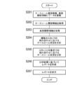
- 5 is an example of an event list stored in a storage unit. It is an example of an operation screen for inputting a response policy for a nurse call displayed on a staff terminal. It is a flowchart which shows the procedure of the report output process in a watching system.
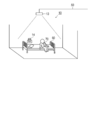
- FIG. 1 is a diagram illustrating an entire configuration of a watching system according to the present embodiment
- FIG. 2 is a diagram illustrating an example of a detection unit installed around a bed in a room of a subject.
- the watching system 1 includes a plurality of detection units 10, a server 20, a fixed terminal 30, and one or more staff terminals 40.
- the server 20 functions as a report output device. These devices are communicably connected to each other by wire or wireless via a network 50 such as a LAN (Local Area Network), a telephone network, or a data communication network.
- the network 50 may include a repeater that relays a communication signal, such as a repeater, a bridge, a router, or a cross-connect.
- the staff terminal 40, the detection unit 10, the server 20, and the fixed terminal 30 are mutually connected by a network 50 such as a wireless LAN (for example, a LAN according to the IEEE 802.11 standard) including an access point 51. Connected for communication.
- the watching system 1 is provided at an appropriate place according to the target person 70.
- the target person 70 (also referred to as a watching target person or a care target person) may be, for example, a patient who needs nursing due to illness or injury, a cared person who needs nursing care due to a decline in physical ability due to aging, or a single person living alone. A single person.
- the target person 70 may be a person who needs to be detected when a predetermined inconvenient event such as an abnormal state occurs in the person.
- the watching system 1 is suitably installed in buildings such as hospitals, welfare facilities for the elderly, and dwelling units, depending on the type of the subject 70.
- the watching system 1 is arranged in a facility including a plurality of rooms (rooms) where a plurality of subjects 70 enter and a plurality of rooms including a nurse station.
- the detection unit 10 is arranged in each living room, which is the observation area of the subject 70.
- the four detection units 10 are arranged in the rooms of the subjects 70, A, B, C, and D, respectively.
- the bed 60 is included in the observation area of the detection unit 10.
- Staff 80 also referred to as care staff or care staff
- who provide nursing or care for the subject 70 carries a staff terminal 40 which is a portable terminal.
- the server 20 may not be located at the nurse station, and may be an external server unit connected to the network 50.
- the fixed terminal 30 may be omitted, and the server 20 or the staff terminal 40 may perform the function.
- FIG. 3 is a block diagram illustrating a schematic configuration of the detection unit.
- the detection unit 10 includes a control unit 11, a communication unit 12, a camera 13, a nurse call unit 14, and a voice input / output unit 15, which are interconnected by a bus.
- the control unit 11 includes a CPU (Central Processing Unit), a RAM (Random Access Memory), and a memory such as a ROM (Read Only Memory), and performs control and arithmetic processing of each unit of the detection unit 10 according to a program.
- the control unit 11 may further include an HDD (Hard ⁇ Disk ⁇ Drive) as a memory.
- the communication unit 12 is an interface circuit (for example, a LAN card) for communicating with another device such as the server 20, the fixed terminal 30, or the staff terminal 40 via the network 50.
- an interface circuit for example, a LAN card
- the camera 13 is arranged, for example, on the ceiling of a living room or on an upper part of a wall, and captures an area including the bed 60 of the subject 70 directly below as an observation area, and outputs a captured image (image data).
- This photographed image includes a still image and a moving image.
- the camera 13 is a near-infrared camera, a visible light camera may be used instead, or these may be used in combination.
- the control unit 11 recognizes the behavior of the target person 70 from the image captured by the camera 13.
- the actions to be recognized include “wake up” from the bed 60, “leaving” away from the bed 60, “fall” falling off the bed 60, and “falling” falling on the floor or the like.
- the control unit 11 detects a silhouette of an image (hereinafter, referred to as a “human silhouette”) from a plurality of captured images (moving images).
- the human silhouette can be detected by, for example, extracting a range of pixels having a relatively large difference by a time difference method of extracting a difference between images whose shooting time is before and after.
- the human silhouette may be detected by a background difference method that extracts a difference between the captured image and the background image. Whether the user is awake, awake, falls, or falls is recognized from the detected person silhouette based on the posture of the subject 70 (for example, standing, sitting, lying down, etc.) and the relative position with respect to the installed object such as the bed 60 in the living room. Is done.
- Such recognition may be performed by a program processed by the CPU of the control unit 11, or may be performed by a built-in processing circuit.
- the present invention is not limited to this, and the server 20 may perform all or most of these recognitions, and the control unit 11 may transmit only the captured image to the server 20.
- the control unit 11 transmits a notification to the effect that the action has occurred to the server 20 or the like.
- the staff 80 is a person who performs various responses to the target person 70 according to the business. Services can include medical services and nursing care services.
- the work of the staff 80 is a care work for the target person 70
- the corresponding contents regarding each event will be described. "Waking up” is determined as an event, and if the determination is within a predetermined time (wake-up time set at the facility (for example, 7 to 8 am), morning care is performed. This morning care includes face washing, tooth brushing assistance, denture wearing, changing clothes assistance, and the like.
- a wheelchair transfer or walking assistance may be required.
- an alert may be generated at a fixed time by the nurse call unit 14 or the like.
- the nurse call unit 14 includes a push-button switch, and detects a nurse call (also called a care call) when the switch is pressed by the subject 70.
- the nurse call may be detected by a voice microphone instead of the push button type switch.
- the control unit 11 sends a notification (nurse call notification) indicating that there is a nurse call via the communication unit 12 and the network 50. It is transmitted to the server 20 or the like.
- the voice input / output unit 15 is, for example, a speaker and a microphone, and enables voice communication by transmitting and receiving a voice signal to / from the staff terminal 40 or the like via the communication unit 12.
- the voice input / output unit 15 may be connected to the detection unit 10 via the communication unit 12 as an external device of the detection unit 10.
- the detection unit 10 also includes a Doppler shift type body motion sensor that transmits and receives microwaves toward the bed 60 and detects Doppler shifts of microwaves caused by body movements (for example, respiratory movements) of the subject 70. May be further provided.
- the body movement sensor detects body movement of the chest (up and down movement of the chest) accompanying the breathing movement of the subject 70, and disorder of the cycle in the body movement of the chest and movement of the chest that is equal to or less than a preset threshold value. When the amplitude at is detected, it is recognized that there is a slight movement abnormality.
- a nurse call by the nurse call unit 14 and a change in the state recognized by the detection unit 10 regarding the subject 70 are included in the staff 80 such as getting up, leaving the bed, falling, falling down, and abnormal body movement.
- An event for which a notification (notification) is to be performed is called an event.
- the detection unit 10 transmits (outputs) information on the event that has occurred and the captured image to the server 20.
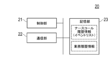
- FIG. 4 is a block diagram showing a schematic configuration of the server.
- the server 20 includes a control unit 21, a communication unit 22, and a storage unit 23.
- the server 20 may be provided in the same building as the living room for the subject 70, or may be provided in a remote location and connectable via a network.
- the server 20 may be a cloud server virtually constructed by a plurality of servers arranged on a network such as the Internet.
- the components are communicably connected to each other by a bus.
- the storage unit 23 functions as a database, and stores an event list (nurse call history information), business history information, and various information related to the target person 70 and the staff 80. This event list includes nurse call history information as described later.
- the control unit 21 functions as an acquisition unit that acquires nurse call history information by cooperating with the communication unit 22. Further, the control unit 21 functions as a creating unit that creates a report in which the analysis result of the situation of the nurse call is visualized. The control unit 21 also functions as an output unit that outputs the created report in cooperation with the communication unit 22.
- the other control unit 21 and communication unit 22 have the same functions as those of the configuration of the detection unit 10, and thus a detailed description is omitted.
- the server 20 determines (identifies) which subject 70 the event, such as a nurse call, getting up, getting out of bed, falling, falling down, etc., detected by the detecting unit 10 is related to.
- the target person 70 that is, the resident of the room
- the determined event type is associated with the target person 70 and added to the event list in the storage unit 23.
- the subject 70 may be determined by reading the IC tag with an RFID reader provided in each room.
- the subject 70 may be determined by arranging the detection unit 10 for each bed 60.
- the entry of each staff 80 into the room may be detected by bringing the staff terminal 40 carried by the staff 80 close to the RFID reader.
- the fixed terminal 30 is a so-called PC (Personal Computer), and includes a control unit including a CPU, a RAM, and the like, a communication unit, a display unit, an input unit, and a voice input / output unit.
- the fixed terminal 30 is arranged, for example, in a nurse station.
- an administrator or a staff member 80 inputs an instruction to display a report in which the analysis result is visualized in a chart or the like on a display unit, or to output a report from an external printer (not shown). Or output to In addition, the report may include a comment input from the fixed terminal 30 by the administrator, the staff 80, or the like.
- the staff 80 or technical staff associates the room number with the detection unit 10 when attaching the detection unit 10 to each room (living room) through the fixed terminal 30, or associates the detection unit 10 with the room 60 such as the bed 60.
- the position information of the installation object that is, the outline information of the ceiling camera 13 viewed upward is calibrated and designated.
- the identification information such as the name and ID number of the subject 70 who is hospitalized or resident is associated with each room number.
- FIG. 5 is a block diagram illustrating a schematic configuration of the staff terminal 40.
- the staff terminal 40 includes a control unit 41, a wireless communication unit 42, a display unit 43, an input unit 44, and an audio input / output unit 45, which are interconnected by a bus.
- the control unit 41 includes a CPU, a RAM, a ROM, and the like as the same configuration as the control unit 11 of the detection unit 10.
- the wireless communication unit 42 enables wireless communication using a standard such as Wi-Fi or Bluetooth (registered trademark), and wirelessly communicates with each device via the access point 51 or directly.
- the display unit 43 and the input unit 44 are touch panels, in which a touch sensor as the input unit 44 is superimposed on the display surface of the display unit 43 formed of liquid crystal or the like.
- the display unit 43 and the input unit 44 display various operation screens displaying a list of a plurality of events included in the event list to the staff 80, and receive various operations through the operation screen.
- the voice input / output unit 45 is, for example, a speaker and a microphone, and enables voice communication by the staff 80 with another staff terminal 40 via the wireless communication unit 42.
- the staff terminal 40 is a device that functions as a user interface of the watching system 1, and can be configured by a portable communication terminal device such as a tablet computer, a smartphone, or a mobile phone.
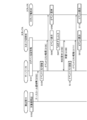
- FIG. 6 is a sequence chart showing the procedure of the processing of the watching system.
- Step S101 The staff 80 performs a login authentication process through the assigned staff terminal 40 at the start of work.
- the staff 80 inputs a staff ID and a password through a login screen (not shown) of the touch panel (the display unit 43 and the input unit 44) of the staff terminal 40.
- the staff terminal 40 transmits this to the server 20.
- the server 20 matches the authentication information stored in the storage unit 23 and transmits an authentication result according to the authority of the staff 80 to the staff terminal 40, thereby completing the login authentication.
- logoff can be performed on a logoff screen (not shown) of the touch panel.
- the time at which the user logged in and the time at which the user logged off are stored in the storage unit 23 of the server 20, and are managed as task history information.
- an event list which will be described later and has occurred within a predetermined period (for example, the past 24 hours), is transmitted to the staff terminal 40, and the staff 80 confirms the situation.
- a predetermined period for example, the past 24 hours
- the login authentication process of step S101 is described only for the staff A among the staff terminals 40 carried by the plurality of staffs 80, but the staff E is also not shown. Similar login processing is performed.
- Steps S102 to S103 The detection unit 10 detects a movement of the subject 70 in the observation area or a nurse call by the subject 70. Then, the detecting unit 10 transmits information on the detected movement of the target person 70 or a nurse call notification to the server 20.
- Step S104 The server 20 updates the event list.
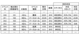
- FIG. 7 is an example of an event list stored in the storage unit 23.
- the events included in the event list include a nurse call, getting up, getting out of bed, falling, and falling as described above.
- the latest event transmitted in step S103 is added to the end of the event list.
- each event includes information of an event ID, a room number, a target person, an event type, an occurrence date and time (time), an image, and a correspondence status, which are primary keys automatically given.
- the image is a still image captured by the detection unit 10 when an event occurs.
- the response status includes a status, a response staff, and a response date and time (time). The correspondence status will be described later.
- the events with event IDs 011 to 0013 and 015 are nurse calls, and the events with event IDs 010 and 014 are leaving and getting up, respectively.
- the events of event IDs 010 to 013 the status of the corresponding status has been handled, and event IDs 014 and 015 are not supported.
- Step S105 When the event list is updated due to a new event being detected and added or the status of the event being changed, the server 20 updates the updated event list with all logged-in staff members. Deliver to terminal 40. Each staff terminal 40 returns an acknowledgment command in response to receiving the event list from the server 20 (not shown).
- the server 20 may transmit the event list by transmitting only the difference data. For example, only the part that has changed from the event list transmitted immediately before, that is, only the event that has been added or updated, is transmitted to all staff terminals 40 as the event list.
- Step S106 Each staff terminal 40 updates the display content of the display unit 43 in response to receiving the event list from the server 20.
- FIG. 8 is an example of an operation screen 431 for inputting a policy for responding to a nurse call displayed on the display unit 43 of the staff terminal 40.
- the operation screen 431 shown in the figure is a screen displayed by the staff 80 transitioning by selecting an arbitrary event from the event list.
- the name of the person who caused the event (Mr. B) and the name of the staff who uses the staff terminal 40 (Staff A) are displayed.
- the elapsed time from the event occurrence time is displayed.
- the target person 70 Mr. B
- both the wake-up event and the nurse call event occur, and the status is unsupported.
- an icon representing an wake-up event other than the selected event is shown.
- the elapsed time (“elapsed 0 minutes”) shown in the area a12 is the elapsed time (rounded down to less than a minute) since the selected nurse call occurred.
- characters indicating a nurse call and an icon are shown.
- a thumbnail image of a captured image at the time of occurrence of a nurse call is displayed.
- the staff 80 operates the "talk” button and the "view” button at the bottom when the thumbnail image is insufficient as information and the user wants to confirm the occurrence status of the subject who has generated the nurse call.
- a call can be made with the target person 70 (Mr. B) through the voice input / output unit 15.
- the “view” button the live video captured by the camera 13 can be viewed by streaming playback.
- the staff 80 decides to take charge of the nurse call (ID015) displayed by operating the “corresponding” button in the area a15. If not, the user returns to the event list screen by operating the return button (triangle icon) in the area a16.
- the prohibition processing for another staff member 80 is performed under the control of the server 20. You. For example, even if another staff member 80 selects the same event (ID015) while a certain staff member 80 is checking the status of an event, the operation screen 431 of the other staff member 80 displays the text “Status Checking”. Is displayed, and the “corresponding” button is not displayed or cannot be selected.
- Steps S108 and S109 The staff terminal 40 transmits a response request for the selected event to the server 20 in response to the operation of the “correspondence” button, and in response, the server 20 returns an approval notification.
- Step S110 The server 20 changes the status of the event list (ID015: nurse call) to “corresponding”.
- the staff 80 operates the above-mentioned “corresponding” button in response to an event selected and displayed on the operation screen 431, the status is changed to “corresponding”. That is, the operation of the "correspondence” button inputs the response status, and records the response date and time assuming that the response has been made. More specifically, in the event list of FIG. 7, the time at which the processing of steps S108 and S109 was performed is recorded in the corresponding date and time column.
- the response date and time may be recorded in the response date and time when the staff 80 entered the room of the target person 70 that has generated an event such as a nurse call, using another operation screen.
- the response result may be input to make the response completed, and the input time may be recorded in the response date and time column.
- Steps S111, S112 The server 20 distributes the event list to each logged-in staff terminal 40 in response to the event list being updated in step S110. Note that the distribution destination at this time may be distributed only to the staff terminal 40 used by the staff 80 in charge of the subject who generated the event.
- the received staff terminal 40 displays the event list on the display unit 43.
- the event list (nurse call history information) recorded when an event such as a nurse call occurs, and the business history information managed according to the login / logoff of the staff 80 are accumulated in the storage unit 23. Is recorded.
- a description will be given of a process of analyzing the occurrence status and response status of the nurse call using the accumulated nurse call history information and business history information, and creating and outputting a report in which the analysis result is visualized.
- FIG. 9 is a flowchart illustrating a procedure of a report output process executed by the watching system 1. 9 is mainly performed by the control unit 21 of the server 20 executing a program stored in the storage unit 23.
- Step S201 The control unit 21 of the server 20 stores the nurse call data in the nurse call history information and the working time data of the staff 80 in the work history information in the storage unit 23. This accumulation process is performed by the above-described process (FIG. 6).
- Step S202 The control unit 21 acquires nurse call history information from the storage unit 23.
- the nurse call history information includes the ID (name) of the target person 70 who has generated the nurse call, the date and time of occurrence, the ID (name) of the corresponding staff 80, and the response date and time.
- Step S203 The control unit 21 acquires the operation history information on the staff 80 from the storage unit 23.
- the work history information records the working hours of the staff 80 in each shift such as night shift, day shift, and the like.
- the work time includes a work start time, an end time, and a break period (start, end) recorded based on the login / logoff time at the staff terminal 40 by the staff 80.
- Step S204 The control unit 21 analyzes the status of the nurse call in the combination of the plurality of staffs, that is, the occurrence status and the response status, from the acquired job history information and nurse call history information.
- FIGS. 10 and 11 are diagrams illustrating examples of analysis results of the number of nurse calls in a combination of a plurality of staff members.
- FIG. 10 shows a graph showing the time transition of the number of nurse calls (per hour) when the staffs A and E become teams and shift to night shift in this combination.
- the lower part of FIG. 10 shows a graph showing the working hours of the staff in the same night shift.
- a period in which a plurality of staffs 80 form a team and work in this combination is extracted using the obtained work history information. Then, by using the acquired nurse call history information, it can be obtained by analyzing the correspondence status of the nurse calls of each staff 80 during the extracted period.
- FIG. 11 is a diagram corresponding to FIG. 10, and shows a time transition of the number of nurse calls when the staffs A and D become teams and shift to night shift on a different day from FIG. It is.
- Step S205 The control unit 21 analyzes the state of the nurse call from the nurse call history information using at least one of the number of occurrences of the nurse call, the number of correspondences, and the response time in the combination of the staff 80 and the target person 70.
- FIG. 12 is a diagram showing an example in which the analysis result of the nurse call situation in the combination of the subject and the staff is visualized.
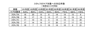
- FIG. 12A is a table showing the number of corresponding nurse calls in each combination of the target person 70 and the staff 80.
- FIG. 12B is a table showing nurse call response times (average) in each combination of the subject 70 and the staff 80.
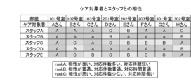
- 12C is a table showing the compatibility of each combination of the subject 70 and the staff 80 based on the tables of FIGS. 12A and 12B.
- the compatibility is from rank A (good compatibility) to rank C (bad).
- the rank A indicates a case where the number of cases is larger than the average level and the response time is shorter than the average level
- the rank C is a case where the number of cases is smaller than the average level and the response time is longer than the average level.
- Rank B is the average level, intermediate rank A and rank C.
- Step S206 The control unit 21 creates a report based on the analysis results in steps S204 and S205.
- Step S207 The control unit 21 outputs a report by displaying it on the display of the fixed terminal 30, printing it on paper from a printer, or transmitting report data to a transmission destination address according to a request.
- FIG. 13 is a diagram illustrating an example of a report that outputs a visualized analysis result.
- FIG. 13 reflects the analysis results shown in FIGS. 10 to 12C and shows a report for a specific period (January) in the facility (building A).
- the report includes a comment, which is input by the manager (for example, the manager managing the staff 80) through the fixed terminal 30, for example.
- the manager can determine the work load and the effect on the target person 70 (resident) (increase / decrease in nurse calls) due to the combination of the staff 80, and the response status of each staff member 80 to the nurse call from each target person 70 (not good) (A nurse call to the subject 70 is not actively dealt with).
- the combination of the staff A and the staff D is greater than the combination of the staff A and the staff C. It can be understood that the number of nurse calls is small with a significant difference.
- the manager can presume that the staff D is familiar with the behavior and nature of each target person 70.
- the staff D confirms that the number of the nurse calls is small even in other combinations. It is presumed that he is familiar with the behavior and nature of. That is, the staff D keeps necessary items at hand so that the subject 70 does not have a chance to make a nurse call at night, keeps the TV on until he falls asleep, and uses the daytime to get good sleep. It is presumed that by making preparations in advance, such as keeping them in the room, they are acting to reduce the number of nurse calls at night.
- the manager can grasp which target person the staff 80 is not good at.
- the administrator can create a comment for the report based on such an estimation or a grasped situation.
- the index for creating such a comment correlation coefficient between the number of nurse calls and the staff 80
- the comment itself can be created by the program itself executed by the server 20.
- FIG. 14 is an example of a graph in the comparative example. This figure simply shows a time transition or a daily transition of the number (unit time) of nurse calls in a certain period.
- FIGS. 10 to 13 it is possible to provide an analysis result that indicates that the number of nurse calls is caused by the combination of the staff 80 and the manner of the staff 80's work.
- FIGS. 10 to 13 it is possible to provide an analysis result that indicates that the number of nurse calls is caused by the combination of the staff 80 and the manner of the staff 80's work.
- FIG. 10 to 13 it is possible to provide an analysis result that indicates that the number of nurse calls is caused by the combination of the staff 80 and the manner of the staff 80's work.
- such a situation cannot be understood from the comparative example of FIG.
- the number of occurrences of nurse calls or the number of correspondences of each staff 80 to a nurse call in the combination of a plurality of staffs 80 based on the acquired nurse call history information or the nurse call history information and the operation history information.
- the work load (light / dark) due to the combination of the staff and the combination of the staff and the resident is analyzed from the data from the detection unit 10 installed in the facility (for example, the nursing facility) and the correspondence record by the staff 80, and the work load is dispersed. Information can be provided to an administrator or the like. Based on the report provided in this manner, the manager can easily and efficiently perform the shift creation of the work, the education of the staff 80, and the work evaluation of the staff.
- the detection unit 10, the server 20, the fixed terminal 30, and the staff terminal 40 have been described as independent devices.
- the present invention is not limited to this, and some configurations may be integrated.
- the functions of the server 20 may be integrated in the fixed terminal 30.
- the processing in the watching system 1 may include steps other than the steps of the above-described sequence chart or flowchart, or may not include some of the above-described steps. Further, the order of the steps is not limited to the above-described embodiment. Further, each step may be executed as one step in combination with another step, may be executed by being included in another step, or may be executed by being divided into a plurality of steps.
- the means and method for performing various processes in the watching system 1 according to the above-described embodiment can be realized by either a dedicated hardware circuit or a programmed computer.
- the above program may be provided by a computer-readable recording medium such as a USB memory or a DVD (Digital Versatile Disc) -ROM, or may be provided online via a network such as the Internet.
- the program recorded on the computer-readable recording medium is usually transferred and stored in a storage unit such as a hard disk.
- the program may be provided as independent application software, or may be incorporated as one function into software of a device such as a detection unit.
Landscapes
- Health & Medical Sciences (AREA)
- General Health & Medical Sciences (AREA)
- General Business, Economics & Management (AREA)
- Engineering & Computer Science (AREA)
- Public Health (AREA)
- Business, Economics & Management (AREA)
- Primary Health Care (AREA)
- Medical Informatics (AREA)
- Epidemiology (AREA)
- Biomedical Technology (AREA)
- Nursing (AREA)
- Life Sciences & Earth Sciences (AREA)
- Animal Behavior & Ethology (AREA)
- Veterinary Medicine (AREA)
- Medical Treatment And Welfare Office Work (AREA)
- Accommodation For Nursing Or Treatment Tables (AREA)
Abstract
L'objectif de la présente invention est de sortir un rapport qui visualise des résultats d'analyse d'appel d'infirmière en tenant compte de combinaisons de membres du personnel 80 prenant en charge des sujets 70. Ce programme de commande amène un ordinateur à exécuter des processus comprenant : une procédure (a) pour acquérir des informations d'historiques d'appels d'infirmière accumulés comprenant, au moins, des informations concernant une occurrence d'un appel d'infirmière à partir d'un sujet 70, et des informations d'un membre du personnel 80 qui a répondu au sujet 70 conformément à l'appel d'infirmière ; une procédure (b) pour analyser l'état d'appels d'infirmières à l'aide du nombre de fois où un appel d'infirmière s'est produit, dans une pluralité de combinaisons des membres du personnel, ou du nombre de fois où chaque membre du personnel 80 a répondu à un appel d'infirmière, à partir des informations d'historiques d'appels d'infirmière acquises dans la procédure (a), pour créer un rapport visualisant les résultats d'analyse ; et une procédure (c) pour sortir le rapport créé dans la procédure (b).
Priority Applications (1)
| Application Number | Priority Date | Filing Date | Title |
|---|---|---|---|
| JP2020527231A JP7268679B2 (ja) | 2018-06-26 | 2019-04-18 | 制御プログラム、レポート出力方法、およびレポート出力装置 |
Applications Claiming Priority (2)
| Application Number | Priority Date | Filing Date | Title |
|---|---|---|---|
| JP2018120827 | 2018-06-26 | ||
| JP2018-120827 | 2018-06-26 |
Publications (1)
| Publication Number | Publication Date |
|---|---|
| WO2020003706A1 true WO2020003706A1 (fr) | 2020-01-02 |
Family
ID=68987039
Family Applications (1)
| Application Number | Title | Priority Date | Filing Date |
|---|---|---|---|
| PCT/JP2019/016687 Ceased WO2020003706A1 (fr) | 2018-06-26 | 2019-04-18 | Programme de commande, procédé de sortie de rapport et dispositif de sortie de rapport |
Country Status (2)
| Country | Link |
|---|---|
| JP (1) | JP7268679B2 (fr) |
| WO (1) | WO2020003706A1 (fr) |
Cited By (10)
| Publication number | Priority date | Publication date | Assignee | Title |
|---|---|---|---|---|
| JP2021189761A (ja) * | 2020-05-29 | 2021-12-13 | コニカミノルタ株式会社 | 算出装置、算出システム、プログラムおよび算出方法 |
| JP2021196937A (ja) * | 2020-06-16 | 2021-12-27 | コニカミノルタ株式会社 | 演算装置、制御プログラム、制御システム、および演算方法 |
| JP2022112781A (ja) * | 2021-01-22 | 2022-08-03 | コニカミノルタ株式会社 | ケア対応支援プログラムおよびケア対応支援システム |
| JP2022113309A (ja) * | 2021-01-25 | 2022-08-04 | コニカミノルタ株式会社 | 情報処理装置、見守りシステム、制御プログラム、および制御方法 |
| JP2022133027A (ja) * | 2021-03-01 | 2022-09-13 | アイホン株式会社 | システム、情報処理方法、およびプログラム |
| JP2022133026A (ja) * | 2021-03-01 | 2022-09-13 | アイホン株式会社 | システム、情報処理方法、およびプログラム |
| JP2023000078A (ja) * | 2021-06-17 | 2023-01-04 | コニカミノルタ株式会社 | 情報処理装置、情報処理システム、稼働状況分析方法、および制御プログラム |
| JP2023000080A (ja) * | 2021-06-17 | 2023-01-04 | コニカミノルタ株式会社 | 情報処理装置、情報処理システム、離脱可能性分析方法、および制御プログラム |
| JP2023000079A (ja) * | 2021-06-17 | 2023-01-04 | コニカミノルタ株式会社 | 情報処理装置、情報処理システム、活用状況分析方法、および制御プログラム |
| JP2025122611A (ja) * | 2024-02-08 | 2025-08-21 | 株式会社Dongriii | 情報処理方法及び情報処理システム |
Citations (1)
| Publication number | Priority date | Publication date | Assignee | Title |
|---|---|---|---|---|
| JP3656705B2 (ja) * | 1998-06-01 | 2005-06-08 | 富士電機機器制御株式会社 | 電圧形インバータ |
-
2019
- 2019-04-18 JP JP2020527231A patent/JP7268679B2/ja active Active
- 2019-04-18 WO PCT/JP2019/016687 patent/WO2020003706A1/fr not_active Ceased
Patent Citations (1)
| Publication number | Priority date | Publication date | Assignee | Title |
|---|---|---|---|---|
| JP3656705B2 (ja) * | 1998-06-01 | 2005-06-08 | 富士電機機器制御株式会社 | 電圧形インバータ |
Non-Patent Citations (3)
| Title |
|---|
| "A solution offering flexibility and safety for cargiving", NICCS, 30 October 2014 (2014-10-30), pages 1 - 38 * |
| "Latest System Report : Konica Minolta Japan/ Care Support Solutions", SENIOR BUSINESS MARKET, vol. 13, no. 11, 1 November 2016 (2016-11-01), pages 74 - 75 * |
| FUNAKI CHIHARU: "General Special Issue : Concrete Measures for cost Reductions Achieved by Cutting-Edge IT", K.K.M.E. PROMOTION ASSOCIATION, MASAYUKI SUGIYAMA, vol. 44, no. 9, 1 September 2017 (2017-09-01), Hakodate Municipal Hospital, pages 44 - 46 * |
Cited By (18)
| Publication number | Priority date | Publication date | Assignee | Title |
|---|---|---|---|---|
| JP7540201B2 (ja) | 2020-05-29 | 2024-08-27 | コニカミノルタ株式会社 | 算出装置、算出システム、プログラムおよび算出方法 |
| JP2021189761A (ja) * | 2020-05-29 | 2021-12-13 | コニカミノルタ株式会社 | 算出装置、算出システム、プログラムおよび算出方法 |
| JP2021196937A (ja) * | 2020-06-16 | 2021-12-27 | コニカミノルタ株式会社 | 演算装置、制御プログラム、制御システム、および演算方法 |
| JP2022112781A (ja) * | 2021-01-22 | 2022-08-03 | コニカミノルタ株式会社 | ケア対応支援プログラムおよびケア対応支援システム |
| JP7753639B2 (ja) | 2021-01-22 | 2025-10-15 | コニカミノルタ株式会社 | ケア対応支援プログラムおよびケア対応支援システム |
| JP2022113309A (ja) * | 2021-01-25 | 2022-08-04 | コニカミノルタ株式会社 | 情報処理装置、見守りシステム、制御プログラム、および制御方法 |
| JP7615705B2 (ja) | 2021-01-25 | 2025-01-17 | コニカミノルタ株式会社 | 情報処理装置、見守りシステム、制御プログラム、および制御方法 |
| JP7631030B2 (ja) | 2021-03-01 | 2025-02-18 | アイホン株式会社 | システム、情報処理方法、およびプログラム |
| JP7620449B2 (ja) | 2021-03-01 | 2025-01-23 | アイホン株式会社 | システム、情報処理方法、およびプログラム |
| JP2022133026A (ja) * | 2021-03-01 | 2022-09-13 | アイホン株式会社 | システム、情報処理方法、およびプログラム |
| JP2022133027A (ja) * | 2021-03-01 | 2022-09-13 | アイホン株式会社 | システム、情報処理方法、およびプログラム |
| JP2023000079A (ja) * | 2021-06-17 | 2023-01-04 | コニカミノルタ株式会社 | 情報処理装置、情報処理システム、活用状況分析方法、および制御プログラム |
| JP2023000080A (ja) * | 2021-06-17 | 2023-01-04 | コニカミノルタ株式会社 | 情報処理装置、情報処理システム、離脱可能性分析方法、および制御プログラム |
| JP2023000078A (ja) * | 2021-06-17 | 2023-01-04 | コニカミノルタ株式会社 | 情報処理装置、情報処理システム、稼働状況分析方法、および制御プログラム |
| JP7739778B2 (ja) | 2021-06-17 | 2025-09-17 | コニカミノルタ株式会社 | 情報処理装置、情報処理システム、離脱可能性分析方法、および制御プログラム |
| JP7760843B2 (ja) | 2021-06-17 | 2025-10-28 | コニカミノルタ株式会社 | 情報処理装置、情報処理システム、稼働状況分析方法、および制御プログラム |
| JP7760844B2 (ja) | 2021-06-17 | 2025-10-28 | コニカミノルタ株式会社 | 情報処理装置、情報処理システム、活用状況分析方法、および制御プログラム |
| JP2025122611A (ja) * | 2024-02-08 | 2025-08-21 | 株式会社Dongriii | 情報処理方法及び情報処理システム |
Also Published As
| Publication number | Publication date |
|---|---|
| JP7268679B2 (ja) | 2023-05-08 |
| JPWO2020003706A1 (ja) | 2021-07-08 |
Similar Documents
| Publication | Publication Date | Title |
|---|---|---|
| JP7268679B2 (ja) | 制御プログラム、レポート出力方法、およびレポート出力装置 | |
| JP7760844B2 (ja) | 情報処理装置、情報処理システム、活用状況分析方法、および制御プログラム | |
| JP7739778B2 (ja) | 情報処理装置、情報処理システム、離脱可能性分析方法、および制御プログラム | |
| JP7234948B2 (ja) | 見守りシステム、およびイベントリストの表示方法 | |
| JP6711474B2 (ja) | システム、システムの制御方法、制御プログラム、およびプログラムを含む装置 | |
| JPWO2019216045A1 (ja) | システム、およびシステムの制御方法 | |
| JPWO2019216044A1 (ja) | システム、およびシステムの制御方法 | |
| JP2024079830A (ja) | 制御プログラム、情報処理装置、情報処理システム、および制御方法 | |
| WO2020003758A1 (fr) | Programme de délivrance de rapport, procédé de délivrance de rapport et dispositif de délivrance de rapport | |
| JP7044060B2 (ja) | 被監視者監視装置、該方法および該システム | |
| JP2018025969A (ja) | 被監視者監視システムの中央処理装置および中央処理方法ならびに被監視者監視システム | |
| JP2020126553A (ja) | 見守りシステム、および見守りシステムの制御プログラム | |
| JP2020052808A (ja) | 見守り装置、見守りシステム、見守りプログラム、および見守り方法 | |
| JP7259540B2 (ja) | 判定装置、判定装置の制御プログラム、および判定方法 | |
| WO2020003715A1 (fr) | Programme de délivrance de rapport, procédé de délivrance de rapport et dispositif de délivrance de rapport | |
| JP2020140418A (ja) | 携帯端末の制御プログラム、携帯端末および見守りシステム | |
| JP7327396B2 (ja) | 制御プログラム、レポート出力方法、およびレポート出力装置 | |
| JP2019197262A (ja) | システムおよびシステムの制御方法 | |
| WO2020003714A1 (fr) | Programme, procédé et dispositif de délivrance de rapport | |
| JPWO2019216066A1 (ja) | システム、およびシステムの制御方法 | |
| JP7760843B2 (ja) | 情報処理装置、情報処理システム、稼働状況分析方法、および制御プログラム | |
| JP2021176036A (ja) | 情報処理装置および情報処理プログラム | |
| JP7615705B2 (ja) | 情報処理装置、見守りシステム、制御プログラム、および制御方法 | |
| JP2021015497A (ja) | 制御装置、制御プログラム、および制御方法 | |
| JP2021015499A (ja) | 制御装置、制御プログラム、および制御方法 |
Legal Events
| Date | Code | Title | Description |
|---|---|---|---|
| 121 | Ep: the epo has been informed by wipo that ep was designated in this application |
Ref document number: 19824778 Country of ref document: EP Kind code of ref document: A1 |
|
| ENP | Entry into the national phase |
Ref document number: 2020527231 Country of ref document: JP Kind code of ref document: A |
|
| NENP | Non-entry into the national phase |
Ref country code: DE |
|
| 122 | Ep: pct application non-entry in european phase |
Ref document number: 19824778 Country of ref document: EP Kind code of ref document: A1 |